EP3756599B1 - Dongle with shape memory - Google Patents
Dongle with shape memory Download PDFInfo
- Publication number
- EP3756599B1 EP3756599B1 EP20175505.5A EP20175505A EP3756599B1 EP 3756599 B1 EP3756599 B1 EP 3756599B1 EP 20175505 A EP20175505 A EP 20175505A EP 3756599 B1 EP3756599 B1 EP 3756599B1
- Authority
- EP
- European Patent Office
- Prior art keywords
- dongle
- catheter
- electrical
- interface unit
- support portion
- Prior art date
- Legal status (The legal status is an assumption and is not a legal conclusion. Google has not performed a legal analysis and makes no representation as to the accuracy of the status listed.)
- Active
Links
Images


Classifications
-
- G—PHYSICS
- G06—COMPUTING OR CALCULATING; COUNTING
- G06F—ELECTRIC DIGITAL DATA PROCESSING
- G06F1/00—Details not covered by groups G06F3/00 - G06F13/00 and G06F21/00
- G06F1/16—Constructional details or arrangements
-
- A—HUMAN NECESSITIES
- A61—MEDICAL OR VETERINARY SCIENCE; HYGIENE
- A61B—DIAGNOSIS; SURGERY; IDENTIFICATION
- A61B18/00—Surgical instruments, devices or methods for transferring non-mechanical forms of energy to or from the body
- A61B18/04—Surgical instruments, devices or methods for transferring non-mechanical forms of energy to or from the body by heating
- A61B18/12—Surgical instruments, devices or methods for transferring non-mechanical forms of energy to or from the body by heating by passing a current through the tissue to be heated, e.g. high-frequency current
- A61B18/14—Probes or electrodes therefor
- A61B18/1492—Probes or electrodes therefor having a flexible, catheter-like structure, e.g. for heart ablation
-
- A—HUMAN NECESSITIES
- A61—MEDICAL OR VETERINARY SCIENCE; HYGIENE
- A61B—DIAGNOSIS; SURGERY; IDENTIFICATION
- A61B34/00—Computer-aided surgery; Manipulators or robots specially adapted for use in surgery
- A61B34/20—Surgical navigation systems; Devices for tracking or guiding surgical instruments, e.g. for frameless stereotaxis
-
- A—HUMAN NECESSITIES
- A61—MEDICAL OR VETERINARY SCIENCE; HYGIENE
- A61B—DIAGNOSIS; SURGERY; IDENTIFICATION
- A61B18/00—Surgical instruments, devices or methods for transferring non-mechanical forms of energy to or from the body
- A61B2018/00053—Mechanical features of the instrument of device
- A61B2018/00172—Connectors and adapters therefor
- A61B2018/00178—Electrical connectors
Definitions
- the present invention relates to a dongle for coupling an electrophysiologic catheter with a patient interface unit.
- Catheterization is used in diagnostic and therapeutic procedures.
- a cardiac catheter is used for mapping and ablation in the heart to treat a variety of cardiac ailments, including cardiac arrhythmias, such as atrial flutter and atrial fibrillation which persist as common and dangerous medical ailments, especially in the aging population.
- cardiac arrhythmias such as atrial flutter and atrial fibrillation which persist as common and dangerous medical ailments, especially in the aging population.
- Diagnosis and treatment of cardiac arrhythmias include mapping the electrical properties of heart tissue, especially the endocardium and the heart volume, and selectively ablating cardiac tissue by application of energy. Such ablation can cease or modify the propagation of unwanted electrical signals from one portion of the heart to another. The ablation process destroys the unwanted electrical pathways by formation of non-conducting lesions.
- Various energy delivery modalities have been disclosed for forming lesions, and include use of microwave, laser and more commonly, radiofrequency energies to create conduction blocks along the cardiac tissue wall.
- microwave, laser and more commonly, radiofrequency energies to create conduction blocks along the cardiac tissue wall.
- ablation--electrical activity at points within the heart is typically sensed and measured by advancing a catheter containing one or more electrical sensors (or electrodes) into the heart, and acquiring data at a multiplicity of points. These data are then utilized to select the endocardial target areas at which ablation is to be performed.
- Electroanatomical navigation systems are used in conjunction with cardiac diagnostic and therapeutic catheters.
- One such system is CARTO available from Biosense Webster of Irwindale, California, which is a 3-D mapping system that provides electrophysiologists with magnetic location technology and visualization data of catheter tip and curve location, anatomical mapping with rapid creation of high-resolution, CT-like maps, and a patient interface unit (PIU) as a central connection for catheters and equipment.
- CARTO available from Biosense Webster of Irwindale, California, which is a 3-D mapping system that provides electrophysiologists with magnetic location technology and visualization data of catheter tip and curve location, anatomical mapping with rapid creation of high-resolution, CT-like maps, and a patient interface unit (PIU) as a central connection for catheters and equipment.
- POU patient interface unit
- Catheters for use with navigation systems have control handles which carry hardware, such as one or more printed circuit boards (PCB).
- PCB printed circuit boards
- one or more circuit boards housed in the control handle may amplify the signals and convert them to a computer readable form before the data is transmitted to a signal processing unit of the navigation system.
- catheter handles are costly, catheters are not easily sterilized so they are intended for single use only and are discarded along with their hardware/metal bearing handles.
- Dongles are known. They are pieces of hardware that attach to a computer or other electronic device and enable additional functions. Dongles typically include at least one interface plug for connection to the computer or other electronic device to enable electrical connection with the same.
- the dongle may include a flexible cable with a second interface plug.
- a free-hanging dongle or a dongle with a flexible cable can be difficult to manage, especially as more dongles are used to temporarily house more components.
- a free-hanging dongle or one with a flexible cable may be prone to damage if knocked or bumped against other equipment and cause additional tension on any extension cable between the dongle and the catheter.
- a free-hanging dongle or one with a flexible cable may be a nuisance to users who resort to using tape or zip-ties to secure or position them.
- the present invention is directed to a system according to claim 1.
- the dongle of the system permits some of the hardware normally carried on the catheter control handle to be relocated so that the catheter -normally intended for single use -- is less costly to manufacture and contain less waste when discarded.
- the dongle having a support portion with flexibility, shape memory and/or varying degrees of stiffness also advantageously allows a user more control over the placement, position and orientation of the dongle.
- the support portion protects both the dongle body, as well as the catheter and the PIU by providing elastic displacement for shock absorption where the dongle or the catheter are accidentally bumped.
- the support portion also decreases the amount of stress and tension imposed on any extension cable that is connecting the catheter to the dongle.
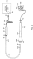
- a catheter-based electroanatomical navigation system 10 is shown for use with a catheter 40, an extension cable 41 and a dongle 42, in accordance with an embodiment of the present invention.
- the system 10 includes at least one monitor 12, a patient interface unit (PIU) 14, a location pad 16, a signal processing unit 20, an ablation energy generator 22, a workstation 24 and a printer 26.
- the monitor 12 displays patient data and maps.
- the PIU 14 allows cable connections between the signal processing unit 20 and all other system components.
- the location pad 16 is for placement under a patient lying on a patient table 18, enabling accurate detection of catheter location.
- the signal processing unit 20 determines all location and performs ECG calculations.
- the generator 22 may be an RF generator for supplying RF energy to the catheter.
- the workstation 24 is a computer adapted for storing patient data and maps.
- the printer 26 is provided to print color maps produced by the system 10.
- the dongle 42 extends between PIU 14 and the catheter 40, providing an electrical connection and performing any function(s) used or necessary for data gathered and transmitted by the catheter to be understood and processed by the system 10.
- the PIU 14 includes at least one electrical connection interface, for example, port 30 configured to interface with the catheter 40 via the dongle 42.
- the catheter 40 has an elongated catheter body 112, a distal section 114 carrying tip and/or ring electrodes 117 and a control handle 116.
- lead wires 140 are connected to the electrodes 117 for receiving and transmitting electronic signals for generating patient data, including 3-D anatomical maps of the patient's heart and ECG readings which are displayed on the monitor 14 and stored in the workstation 24.
- electromagnetic position sensor(s) carried in the distal section 114 are responsive to external magnetic fields generated by the location pad 16 below the patient table 18 for generating electrical signals representative of the location of the distal tip section.
- Sensor cables 132 are connected from the position sensors to transmit these signals.
- Both the lead wires 140 and the sensor cables 132 extend through the length of the catheter, passing through the distal tip section 114, the catheter body 112 and the control handle 116.
- a proximal end 116P of the control handle has at least one electrical connection port 30 to enable electrical connection with the lead wires 140 and sensor cables 132.
- the extension cable 41 between the catheter 40 and the dongle 42 has a proximal end 41P and a distal end 41D, as shown in FIG. 2 .
- the distal end 4 ID is provided with a first interface, for example, plug 43 configured to be received in the electrical connection port 30 at the proximal end 116P of the control handle.
- the proximal end 41P is provided with a second interface, for example, plug 44 configured to be received in an electrical interface, for example, port 45 provided in a distal end of the dongle 42.
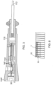
- the dongle 42 has a proximal support portion including a semi-rigid dongle cable 53, and an elongated distal body or housing 54 with a proximal end 54P, a distal end 54D and a generally sealed interior cavity extending therebetween, as shown in FIG. 4 .
- the electrical port 45 is configured to receive the second interface plug 44 of the extension cable 41.
- an electrical interface, for example, plug 55 is configured to be received in the electrical port 30 of the PIU 14.
- the dongle 42 houses hardware, for example, at least one printed circuit board (PCB) 60 which receives the electrical signals representative of catheter location transmitted by the sensor cables 136 to through the extension cable.
- the PCB 60 may amplify the signals and convert to a form readable by the signal processing unit 20 of the system 10 which are then transmitted via the proximal dongle cable 53.
- the proximal cable 53 has an elongated flexible outer tubing member 62 defining a lumen 63 through which dongle wires 64 extend between the proximal and distal ends of the cable.
- the cable 53 is semi-rigid with shape memory so that the cable can be manipulated and configured by a user to selectively position or orient the dongle body 54 as desired.
- the outer tubing member 62 comprises spirally wound flat strip(s) 67 of metal, metal alloy or generally rigid plastic material with longitudinal folds 69, interlocking adjacent longitudinal side edges 71 to form what is commonly referred to as a "gooseneck" tubular structure with a corrugated-like profile which provides flexibility and shape memory such that it can be manipulated into and retain a variety of desired configurations.
- the tubular structure may also act as a strain relief and/or a trunk cable insulation covering.
- the wires 64 extending through the tubing member 62 are protected and sealed within the tubing member 62.
- FIG. 6 illustrates another embodiment of a flexible cable or gooseneck tubular structure comprising an inner coiled spring 80 and an outer sectional wire 82 wrapped around the coiled spring 80.
- the underlying wire of the spring 80 has a circular cross-section and the outer sectional wire 82 has a triangular cross-section, wherein the underlying wire of the spring 80 is nested between two inner vertices V of adjacent pairs of sectional wires 82.
- the dongle 42 is connected to the PIU 14 via the connector plug 55 being received in the connector port 30, as shown in FIG. 2 .
- a distal end of the dongle 42 receives the proximal connector 44 of the extension cable 41.
- the distal connector 43 of the extension cable 41 is received in the connector port 30 of the control handle 116.
- the signals are transmitted via the lead wires 114 through the distal tip section 114, the catheter body 112 and the control handle 116.
- the signals are transmitted from the control handle 116 to the PIU 14 for processing by the signal processing unit 20 by the extension cable 41 and the dongle 42.
- RF energy from the RF generator 22 of the system 10 is delivered to the tip and ring electrodes 117 via the PIU 14, the dongle 42, the extension cable, and the lead wires 140 extending through the control handle 116, the catheter body 112 and the distal tip section 114.
- electrical signals from the position sensors carried in the catheter distal tip section are transmitted via the sensor cables 132 which extends from the distal tip section, to the catheter body 12, and the control handle 116.
- the signals are further transmitted via the extension cable 41 to the dongle 42 which provides the PCB 60 that may amplify and/or convert the signals before transmitting them to the PIU 14 for processing by the signal processing unit 20 of the system 20.
- the dongle of the present invention renders a catheter more disposable and "greener” by allowing expensive and metal-bearing hardware to be relocated from the catheter and onto the dongle.
- the semi-rigid dongle of the present invention reduces the risk of damage to the dongle, the catheter and the navigation system by allowing the user more selection in the placement and positioning of the dongle.
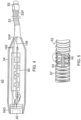
- a dongle 42' is illustrated with a proximal support portion including a semi-rigid dongle arm 66 whose proximal end carries the electrical plug 55.
- the arm 66 comprises a tightly coiled spring whose diameter may vary or be uniform throughout the length of the arm.
- the wires 64 extending through the spring are protected by the spring.
- the spring may be manufactured with different degrees of stiffness depending on the use and application, and be provided with a preformed shape. In the disclosed embodiment, the spring has sufficient stiffness to support the dongle body in a horizontal position but allows elastic bending or displacement where the dongle body is accidentally bumped.
- the body of the dongle may house a variety of electrical hardware for receiving and processing (including, for example, amplifying, converting, digitizing, etc.) a variety of electrical signals (including, for example, optical, audio, etc.) between the catheter and the navigation system, as needed or appropriate.
Landscapes
- Health & Medical Sciences (AREA)
- Engineering & Computer Science (AREA)
- Surgery (AREA)
- Life Sciences & Earth Sciences (AREA)
- Nuclear Medicine, Radiotherapy & Molecular Imaging (AREA)
- Veterinary Medicine (AREA)
- Public Health (AREA)
- Biomedical Technology (AREA)
- Heart & Thoracic Surgery (AREA)
- Medical Informatics (AREA)
- Molecular Biology (AREA)
- Animal Behavior & Ethology (AREA)
- General Health & Medical Sciences (AREA)
- Physics & Mathematics (AREA)
- Theoretical Computer Science (AREA)
- Otolaryngology (AREA)
- Plasma & Fusion (AREA)
- Robotics (AREA)
- Cardiology (AREA)
- Human Computer Interaction (AREA)
- General Engineering & Computer Science (AREA)
- General Physics & Mathematics (AREA)
- Media Introduction/Drainage Providing Device (AREA)
- Measurement And Recording Of Electrical Phenomena And Electrical Characteristics Of The Living Body (AREA)
- Surgical Instruments (AREA)
- Electrotherapy Devices (AREA)
Applications Claiming Priority (2)
| Application Number | Priority Date | Filing Date | Title |
|---|---|---|---|
| US13/826,545 US9703317B2 (en) | 2013-03-14 | 2013-03-14 | Dongle with shape memory |
| EP14159366.5A EP2799025B1 (en) | 2013-03-14 | 2014-03-13 | Dongle with shape memory |
Related Parent Applications (1)
| Application Number | Title | Priority Date | Filing Date |
|---|---|---|---|
| EP14159366.5A Division EP2799025B1 (en) | 2013-03-14 | 2014-03-13 | Dongle with shape memory |
Publications (3)
| Publication Number | Publication Date |
|---|---|
| EP3756599A1 EP3756599A1 (en) | 2020-12-30 |
| EP3756599B1 true EP3756599B1 (en) | 2024-01-31 |
| EP3756599C0 EP3756599C0 (en) | 2024-01-31 |
Family
ID=50280176
Family Applications (2)
| Application Number | Title | Priority Date | Filing Date |
|---|---|---|---|
| EP14159366.5A Active EP2799025B1 (en) | 2013-03-14 | 2014-03-13 | Dongle with shape memory |
| EP20175505.5A Active EP3756599B1 (en) | 2013-03-14 | 2014-03-13 | Dongle with shape memory |
Family Applications Before (1)
| Application Number | Title | Priority Date | Filing Date |
|---|---|---|---|
| EP14159366.5A Active EP2799025B1 (en) | 2013-03-14 | 2014-03-13 | Dongle with shape memory |
Country Status (8)
| Country | Link |
|---|---|
| US (3) | US9703317B2 (enExample) |
| EP (2) | EP2799025B1 (enExample) |
| JP (2) | JP6727748B2 (enExample) |
| CN (1) | CN104042206B (enExample) |
| AU (2) | AU2014201283A1 (enExample) |
| CA (1) | CA2846205A1 (enExample) |
| IL (1) | IL231303B (enExample) |
| RU (1) | RU2014109795A (enExample) |
Families Citing this family (4)
| Publication number | Priority date | Publication date | Assignee | Title |
|---|---|---|---|---|
| US9703317B2 (en) * | 2013-03-14 | 2017-07-11 | Biosense Webster (Israel) Ltd. | Dongle with shape memory |
| CN107743381A (zh) * | 2015-06-12 | 2018-02-27 | 皇家飞利浦有限公司 | 电磁设备跟踪 |
| CN109891677A (zh) * | 2016-11-16 | 2019-06-14 | 圣犹达医疗用品心脏病学部门有限公司 | 用于医疗装置的高容量连接器 |
| RU2735592C1 (ru) * | 2017-10-18 | 2020-11-05 | Джапан Тобакко Инк. | Устройство, генерирующее компонент для вдыхания, способ управления устройством, генерирующим компонент для вдыхания, и компьютерно-читаемый носитель данных |
Family Cites Families (53)
| Publication number | Priority date | Publication date | Assignee | Title |
|---|---|---|---|---|
| US1218570A (en) | 1916-08-17 | 1917-03-06 | Concordia Safety Lamp Company Inc | Miner's safety electric lamp. |
| US1810439A (en) * | 1928-05-15 | 1931-06-16 | Michael A Rollman | Electric plug |
| US2101713A (en) | 1936-04-25 | 1937-12-07 | Okonite Co | Electric connecter or terminal |
| US2178621A (en) | 1937-02-01 | 1939-11-07 | Belden Mfg Co | Electrical connector |
| US2724736A (en) | 1953-02-27 | 1955-11-22 | Jr Ferdinand Klumpp | Spring type strain-relief bushing |
| US2971178A (en) | 1956-02-13 | 1961-02-07 | Welex Inc | Flexible connector for conductor core cable |
| US4753223A (en) * | 1986-11-07 | 1988-06-28 | Bremer Paul W | System for controlling shape and direction of a catheter, cannula, electrode, endoscope or similar article |
| US5163445A (en) * | 1987-04-10 | 1992-11-17 | Cardiometrics, Inc. | Apparatus, system and method for measuring spatial average velocity and/or volumetric flow of blood in a vessel and screw joint for use therewith |
| US4815471A (en) * | 1988-08-01 | 1989-03-28 | Precision Interconnect Corporation | Catheter assembly |
| US5118907A (en) * | 1989-11-13 | 1992-06-02 | Stout Thomas D | System and method for medical device interconnection utilizing controlled dispensing of elongated interconnecting member |
| AU4026793A (en) * | 1992-04-10 | 1993-11-18 | Cardiorhythm | Shapable handle for steerable electrode catheter |
| US5465894A (en) * | 1993-12-06 | 1995-11-14 | Ethicon, Inc. | Surgical stapling instrument with articulated stapling head assembly on rotatable and flexible support shaft |
| IT1273836B (it) * | 1994-03-15 | 1997-07-10 | Xtrode Srl | Perfezionamento ad un dispositivo adattatore per elettrocateteri |
| JP3682066B2 (ja) * | 1994-06-27 | 2005-08-10 | ボストン サイエンティフィック リミテッド | 人体組織の加熱アブレーションのための非線形制御システム及び方法 |
| US5941818A (en) | 1996-10-01 | 1999-08-24 | Vista Medical Technologies, Inc. | Endoscopic video camera with malleable support |
| US5823817A (en) | 1996-10-24 | 1998-10-20 | Hamilton Beach/Proctor-Silex, Inc. | Cord guard |
| JPH10258031A (ja) * | 1997-03-17 | 1998-09-29 | Fuji Photo Optical Co Ltd | 内視鏡装置 |
| US5874709A (en) | 1997-04-14 | 1999-02-23 | Tweco Products, Inc. | Strain relief assembly for welding cable |
| IL132226A0 (en) * | 1998-02-10 | 2001-03-19 | Biosense Inc | Improved catheter calibration |
| CA2273467C (en) * | 1998-06-04 | 2009-02-17 | Cordis Webster, Inc. | Catheter for injecting therapeutic and diagnostic agents |
| US6569160B1 (en) | 2000-07-07 | 2003-05-27 | Biosense, Inc. | System and method for detecting electrode-tissue contact |
| AU2002236565A1 (en) * | 2000-12-15 | 2002-06-24 | Alsius Corporation | Radio frequency patient heating system |
| US20070038056A1 (en) * | 2001-10-11 | 2007-02-15 | Carlo Pappone | System and methods for locating and ablating arrhythomogenic tissues |
| US6908442B2 (en) * | 2001-11-07 | 2005-06-21 | Radi Medical Systems Ab | Bending resistant male connector for a guide wire |
| US6663570B2 (en) * | 2002-02-27 | 2003-12-16 | Volcano Therapeutics, Inc. | Connector for interfacing intravascular sensors to a physiology monitor |
| JP2003281943A (ja) | 2002-03-20 | 2003-10-03 | Sony Corp | 信号伝送ケーブル及び電子機器 |
| US20130197555A1 (en) * | 2002-07-01 | 2013-08-01 | Recor Medical, Inc. | Intraluminal devices and methods for denervation |
| US7001383B2 (en) * | 2002-10-21 | 2006-02-21 | Biosense, Inc. | Real-time monitoring and mapping of ablation lesion formation in the heart |
| US20040220461A1 (en) * | 2003-04-29 | 2004-11-04 | Yitzhack Schwartz | Transseptal facilitation using sheath with electrode arrangement |
| US6875924B2 (en) | 2003-09-09 | 2005-04-05 | Uniprise International, Inc. | Extendible flexible electrical conduit with conductors therein |
| US9555223B2 (en) * | 2004-03-23 | 2017-01-31 | Medtronic Cryocath Lp | Method and apparatus for inflating and deflating balloon catheters |
| CN101309651B (zh) * | 2005-06-20 | 2011-12-07 | 麦德托尼克消融前沿有限公司 | 消融导管 |
| US8355801B2 (en) * | 2005-09-26 | 2013-01-15 | Biosense Webster, Inc. | System and method for measuring esophagus proximity |
| US8798711B2 (en) * | 2006-02-09 | 2014-08-05 | Biosense Webster, Inc. | Shielding of catheter handle |
| RU2417732C2 (ru) * | 2006-10-10 | 2011-05-10 | Байосенс Уэбстер, Инк. | Катетер для картрирования пищевода |
| US7558899B2 (en) | 2007-04-04 | 2009-07-07 | Imation Corp. | Dongle configured to electrically couple a data storage device and a host computing device |
| US20090254083A1 (en) * | 2008-03-10 | 2009-10-08 | Hansen Medical, Inc. | Robotic ablation catheter |
| US20100273355A1 (en) * | 2009-04-22 | 2010-10-28 | Tyco Electronics Corporation | Image guide wire connection |
| US9775664B2 (en) * | 2009-09-22 | 2017-10-03 | Mederi Therapeutics, Inc. | Systems and methods for treating tissue with radiofrequency energy |
| AU2010300677B2 (en) | 2009-09-29 | 2014-09-04 | C.R. Bard, Inc. | Stylets for use with apparatus for intravascular placement of a catheter |
| US9445859B2 (en) * | 2010-01-29 | 2016-09-20 | Medtronic Cryocath Lp | Multifunctional ablation device |
| US20110308835A1 (en) * | 2010-06-16 | 2011-12-22 | Piekny Mark G | Self-coiling apparatus |
| US20110312211A1 (en) | 2010-06-22 | 2011-12-22 | John Mezzalingua Associates, Inc. | Strain relief accessory for coaxial cable connector |
| US20120109118A1 (en) * | 2010-10-29 | 2012-05-03 | Medtronic Ablation Frontiers Llc | Cryogenic-radiofrequency ablation system |
| US9662169B2 (en) * | 2011-07-30 | 2017-05-30 | Biosense Webster (Israel) Ltd. | Catheter with flow balancing valve |
| US20130296729A1 (en) * | 2012-05-04 | 2013-11-07 | Biosense Webster (Israel), Ltd. | Catheter having two-piece connector for a split handle assembly |
| WO2014121664A1 (zh) * | 2013-02-07 | 2014-08-14 | 上海魅丽纬叶医疗科技有限公司 | 射频消融方法、系统及其射频消融设备 |
| US9703317B2 (en) * | 2013-03-14 | 2017-07-11 | Biosense Webster (Israel) Ltd. | Dongle with shape memory |
| US9987070B2 (en) * | 2013-03-15 | 2018-06-05 | St. Jude Medical, Cardiology Division, Inc. | Ablation system, methods, and controllers |
| US20140317884A1 (en) * | 2013-03-15 | 2014-10-30 | Todd J. Cohen | Gripping system for medical devices to improve haptics and prevent hand fatigue |
| US20140276771A1 (en) * | 2013-03-15 | 2014-09-18 | Volcano Corporation | Systems and methods for controlled tissue ablation |
| US20150270634A1 (en) * | 2014-03-21 | 2015-09-24 | St. Jude Medical, Cardiology Division, Inc. | Electrode assembly for catheter system including struts having a non-uniform thickness |
| US9848943B2 (en) * | 2014-04-18 | 2017-12-26 | Biosense Webster (Israel) Ltd. | Ablation catheter with dedicated fluid paths and needle centering insert |
-
2013
- 2013-03-14 US US13/826,545 patent/US9703317B2/en active Active
-
2014
- 2014-03-04 IL IL231303A patent/IL231303B/en active IP Right Grant
- 2014-03-07 AU AU2014201283A patent/AU2014201283A1/en not_active Abandoned
- 2014-03-12 CA CA2846205A patent/CA2846205A1/en not_active Abandoned
- 2014-03-13 EP EP14159366.5A patent/EP2799025B1/en active Active
- 2014-03-13 EP EP20175505.5A patent/EP3756599B1/en active Active
- 2014-03-13 JP JP2014050110A patent/JP6727748B2/ja active Active
- 2014-03-13 RU RU2014109795/14A patent/RU2014109795A/ru not_active Application Discontinuation
- 2014-03-14 CN CN201410095273.9A patent/CN104042206B/zh active Active
-
2017
- 2017-07-10 US US15/646,015 patent/US10234897B2/en active Active
-
2018
- 2018-09-14 JP JP2018172286A patent/JP6707597B2/ja active Active
- 2018-10-29 AU AU2018255539A patent/AU2018255539A1/en not_active Abandoned
-
2019
- 2019-03-18 US US16/357,150 patent/US10664008B2/en active Active
Also Published As
| Publication number | Publication date |
|---|---|
| US20140273631A1 (en) | 2014-09-18 |
| US20170371369A1 (en) | 2017-12-28 |
| EP2799025A2 (en) | 2014-11-05 |
| EP2799025A3 (en) | 2014-11-26 |
| RU2014109795A (ru) | 2015-09-20 |
| JP6727748B2 (ja) | 2020-07-22 |
| CN104042206A (zh) | 2014-09-17 |
| AU2014201283A1 (en) | 2014-10-02 |
| US10234897B2 (en) | 2019-03-19 |
| IL231303B (en) | 2018-12-31 |
| JP2018198981A (ja) | 2018-12-20 |
| JP2014176690A (ja) | 2014-09-25 |
| US10664008B2 (en) | 2020-05-26 |
| IL231303A0 (en) | 2014-08-31 |
| EP2799025B1 (en) | 2020-05-20 |
| AU2018255539A1 (en) | 2018-11-22 |
| EP3756599C0 (en) | 2024-01-31 |
| EP3756599A1 (en) | 2020-12-30 |
| US9703317B2 (en) | 2017-07-11 |
| CA2846205A1 (en) | 2014-09-14 |
| CN104042206B (zh) | 2020-01-07 |
| JP6707597B2 (ja) | 2020-06-10 |
| US20190212771A1 (en) | 2019-07-11 |
Similar Documents
| Publication | Publication Date | Title |
|---|---|---|
| US11065052B2 (en) | Catheter electrode assemblies and methods of construction therefor | |
| US12465721B2 (en) | Controllable expandable catheter | |
| JP6209669B2 (ja) | カテーテル電極のイントロデューサへの進入及びイントロデューサからの退出を検出するためのシステム | |
| EP2915498B1 (en) | Multi-arm catheter with signal transmission over braid wires | |
| US10664008B2 (en) | Catheter-based system having dongle with shape memory | |
| US9820677B2 (en) | Cointegration filter for a catheter navigation system | |
| JP6230826B2 (ja) | ベース無線トランシーバーつきの無線カテーテル | |
| US20220008011A1 (en) | Printed sensor coil | |
| US20210244360A1 (en) | Sensing, mapping, and therapy catheter with multiple catheterlets | |
| US11707231B2 (en) | Apparatuses, methods, and systems for contact force sensing |
Legal Events
| Date | Code | Title | Description |
|---|---|---|---|
| PUAI | Public reference made under article 153(3) epc to a published international application that has entered the european phase |
Free format text: ORIGINAL CODE: 0009012 |
|
| STAA | Information on the status of an ep patent application or granted ep patent |
Free format text: STATUS: THE APPLICATION HAS BEEN PUBLISHED |
|
| AC | Divisional application: reference to earlier application |
Ref document number: 2799025 Country of ref document: EP Kind code of ref document: P |
|
| AK | Designated contracting states |
Kind code of ref document: A1 Designated state(s): AL AT BE BG CH CY CZ DE DK EE ES FI FR GB GR HR HU IE IS IT LI LT LU LV MC MK MT NL NO PL PT RO RS SE SI SK SM TR |
|
| STAA | Information on the status of an ep patent application or granted ep patent |
Free format text: STATUS: REQUEST FOR EXAMINATION WAS MADE |
|
| 17P | Request for examination filed |
Effective date: 20210505 |
|
| RBV | Designated contracting states (corrected) |
Designated state(s): AL AT BE BG CH CY CZ DE DK EE ES FI FR GB GR HR HU IE IS IT LI LT LU LV MC MK MT NL NO PL PT RO RS SE SI SK SM TR |
|
| RAP3 | Party data changed (applicant data changed or rights of an application transferred) |
Owner name: BIOSENSE WEBSTER (ISRAEL) LTD. |
|
| GRAP | Despatch of communication of intention to grant a patent |
Free format text: ORIGINAL CODE: EPIDOSNIGR1 |
|
| STAA | Information on the status of an ep patent application or granted ep patent |
Free format text: STATUS: GRANT OF PATENT IS INTENDED |
|
| INTG | Intention to grant announced |
Effective date: 20230703 |
|
| GRAS | Grant fee paid |
Free format text: ORIGINAL CODE: EPIDOSNIGR3 |
|
| GRAA | (expected) grant |
Free format text: ORIGINAL CODE: 0009210 |
|
| STAA | Information on the status of an ep patent application or granted ep patent |
Free format text: STATUS: THE PATENT HAS BEEN GRANTED |
|
| AC | Divisional application: reference to earlier application |
Ref document number: 2799025 Country of ref document: EP Kind code of ref document: P |
|
| AK | Designated contracting states |
Kind code of ref document: B1 Designated state(s): AL AT BE BG CH CY CZ DE DK EE ES FI FR GB GR HR HU IE IS IT LI LT LU LV MC MK MT NL NO PL PT RO RS SE SI SK SM TR |
|
| REG | Reference to a national code |
Ref country code: GB Ref legal event code: FG4D Ref country code: CH Ref legal event code: EP |
|
| REG | Reference to a national code |
Ref country code: DE Ref legal event code: R096 Ref document number: 602014089434 Country of ref document: DE |
|
| REG | Reference to a national code |
Ref country code: IE Ref legal event code: FG4D |
|
| U01 | Request for unitary effect filed |
Effective date: 20240213 |
|
| U07 | Unitary effect registered |
Designated state(s): AT BE BG DE DK EE FI FR IT LT LU LV MT NL PT SE SI Effective date: 20240223 |
|
| U20 | Renewal fee for the european patent with unitary effect paid |
Year of fee payment: 11 Effective date: 20240301 |
|
| PG25 | Lapsed in a contracting state [announced via postgrant information from national office to epo] |
Ref country code: IS Free format text: LAPSE BECAUSE OF FAILURE TO SUBMIT A TRANSLATION OF THE DESCRIPTION OR TO PAY THE FEE WITHIN THE PRESCRIBED TIME-LIMIT Effective date: 20240531 |
|
| PG25 | Lapsed in a contracting state [announced via postgrant information from national office to epo] |
Ref country code: GR Free format text: LAPSE BECAUSE OF FAILURE TO SUBMIT A TRANSLATION OF THE DESCRIPTION OR TO PAY THE FEE WITHIN THE PRESCRIBED TIME-LIMIT Effective date: 20240501 |
|
| PG25 | Lapsed in a contracting state [announced via postgrant information from national office to epo] |
Ref country code: RS Free format text: LAPSE BECAUSE OF FAILURE TO SUBMIT A TRANSLATION OF THE DESCRIPTION OR TO PAY THE FEE WITHIN THE PRESCRIBED TIME-LIMIT Effective date: 20240430 Ref country code: HR Free format text: LAPSE BECAUSE OF FAILURE TO SUBMIT A TRANSLATION OF THE DESCRIPTION OR TO PAY THE FEE WITHIN THE PRESCRIBED TIME-LIMIT Effective date: 20240131 |
|
| PG25 | Lapsed in a contracting state [announced via postgrant information from national office to epo] |
Ref country code: ES Free format text: LAPSE BECAUSE OF FAILURE TO SUBMIT A TRANSLATION OF THE DESCRIPTION OR TO PAY THE FEE WITHIN THE PRESCRIBED TIME-LIMIT Effective date: 20240131 |
|
| PG25 | Lapsed in a contracting state [announced via postgrant information from national office to epo] |
Ref country code: RS Free format text: LAPSE BECAUSE OF FAILURE TO SUBMIT A TRANSLATION OF THE DESCRIPTION OR TO PAY THE FEE WITHIN THE PRESCRIBED TIME-LIMIT Effective date: 20240430 Ref country code: NO Free format text: LAPSE BECAUSE OF FAILURE TO SUBMIT A TRANSLATION OF THE DESCRIPTION OR TO PAY THE FEE WITHIN THE PRESCRIBED TIME-LIMIT Effective date: 20240430 Ref country code: IS Free format text: LAPSE BECAUSE OF FAILURE TO SUBMIT A TRANSLATION OF THE DESCRIPTION OR TO PAY THE FEE WITHIN THE PRESCRIBED TIME-LIMIT Effective date: 20240531 Ref country code: HR Free format text: LAPSE BECAUSE OF FAILURE TO SUBMIT A TRANSLATION OF THE DESCRIPTION OR TO PAY THE FEE WITHIN THE PRESCRIBED TIME-LIMIT Effective date: 20240131 Ref country code: GR Free format text: LAPSE BECAUSE OF FAILURE TO SUBMIT A TRANSLATION OF THE DESCRIPTION OR TO PAY THE FEE WITHIN THE PRESCRIBED TIME-LIMIT Effective date: 20240501 Ref country code: ES Free format text: LAPSE BECAUSE OF FAILURE TO SUBMIT A TRANSLATION OF THE DESCRIPTION OR TO PAY THE FEE WITHIN THE PRESCRIBED TIME-LIMIT Effective date: 20240131 |
|
| PG25 | Lapsed in a contracting state [announced via postgrant information from national office to epo] |
Ref country code: PL Free format text: LAPSE BECAUSE OF FAILURE TO SUBMIT A TRANSLATION OF THE DESCRIPTION OR TO PAY THE FEE WITHIN THE PRESCRIBED TIME-LIMIT Effective date: 20240131 |
|
| PG25 | Lapsed in a contracting state [announced via postgrant information from national office to epo] |
Ref country code: PL Free format text: LAPSE BECAUSE OF FAILURE TO SUBMIT A TRANSLATION OF THE DESCRIPTION OR TO PAY THE FEE WITHIN THE PRESCRIBED TIME-LIMIT Effective date: 20240131 |
|
| PG25 | Lapsed in a contracting state [announced via postgrant information from national office to epo] |
Ref country code: SM Free format text: LAPSE BECAUSE OF FAILURE TO SUBMIT A TRANSLATION OF THE DESCRIPTION OR TO PAY THE FEE WITHIN THE PRESCRIBED TIME-LIMIT Effective date: 20240131 |
|
| PG25 | Lapsed in a contracting state [announced via postgrant information from national office to epo] |
Ref country code: CZ Free format text: LAPSE BECAUSE OF FAILURE TO SUBMIT A TRANSLATION OF THE DESCRIPTION OR TO PAY THE FEE WITHIN THE PRESCRIBED TIME-LIMIT Effective date: 20240131 |
|
| PG25 | Lapsed in a contracting state [announced via postgrant information from national office to epo] |
Ref country code: SK Free format text: LAPSE BECAUSE OF FAILURE TO SUBMIT A TRANSLATION OF THE DESCRIPTION OR TO PAY THE FEE WITHIN THE PRESCRIBED TIME-LIMIT Effective date: 20240131 |
|
| PG25 | Lapsed in a contracting state [announced via postgrant information from national office to epo] |
Ref country code: SM Free format text: LAPSE BECAUSE OF FAILURE TO SUBMIT A TRANSLATION OF THE DESCRIPTION OR TO PAY THE FEE WITHIN THE PRESCRIBED TIME-LIMIT Effective date: 20240131 Ref country code: SK Free format text: LAPSE BECAUSE OF FAILURE TO SUBMIT A TRANSLATION OF THE DESCRIPTION OR TO PAY THE FEE WITHIN THE PRESCRIBED TIME-LIMIT Effective date: 20240131 Ref country code: RO Free format text: LAPSE BECAUSE OF FAILURE TO SUBMIT A TRANSLATION OF THE DESCRIPTION OR TO PAY THE FEE WITHIN THE PRESCRIBED TIME-LIMIT Effective date: 20240131 Ref country code: CZ Free format text: LAPSE BECAUSE OF FAILURE TO SUBMIT A TRANSLATION OF THE DESCRIPTION OR TO PAY THE FEE WITHIN THE PRESCRIBED TIME-LIMIT Effective date: 20240131 |
|
| REG | Reference to a national code |
Ref country code: CH Ref legal event code: PL |
|
| REG | Reference to a national code |
Ref country code: DE Ref legal event code: R097 Ref document number: 602014089434 Country of ref document: DE |
|
| PG25 | Lapsed in a contracting state [announced via postgrant information from national office to epo] |
Ref country code: MC Free format text: LAPSE BECAUSE OF FAILURE TO SUBMIT A TRANSLATION OF THE DESCRIPTION OR TO PAY THE FEE WITHIN THE PRESCRIBED TIME-LIMIT Effective date: 20240131 |
|
| PG25 | Lapsed in a contracting state [announced via postgrant information from national office to epo] |
Ref country code: MC Free format text: LAPSE BECAUSE OF FAILURE TO SUBMIT A TRANSLATION OF THE DESCRIPTION OR TO PAY THE FEE WITHIN THE PRESCRIBED TIME-LIMIT Effective date: 20240131 |
|
| PLBE | No opposition filed within time limit |
Free format text: ORIGINAL CODE: 0009261 |
|
| STAA | Information on the status of an ep patent application or granted ep patent |
Free format text: STATUS: NO OPPOSITION FILED WITHIN TIME LIMIT |
|
| 26N | No opposition filed |
Effective date: 20241101 |
|
| PG25 | Lapsed in a contracting state [announced via postgrant information from national office to epo] |
Ref country code: IE Free format text: LAPSE BECAUSE OF NON-PAYMENT OF DUE FEES Effective date: 20240313 |
|
| PG25 | Lapsed in a contracting state [announced via postgrant information from national office to epo] |
Ref country code: IE Free format text: LAPSE BECAUSE OF NON-PAYMENT OF DUE FEES Effective date: 20240313 Ref country code: CH Free format text: LAPSE BECAUSE OF NON-PAYMENT OF DUE FEES Effective date: 20240331 |
|
| U20 | Renewal fee for the european patent with unitary effect paid |
Year of fee payment: 12 Effective date: 20250205 |
|
| PGFP | Annual fee paid to national office [announced via postgrant information from national office to epo] |
Ref country code: GB Payment date: 20250130 Year of fee payment: 12 |
|
| PG25 | Lapsed in a contracting state [announced via postgrant information from national office to epo] |
Ref country code: CY Free format text: LAPSE BECAUSE OF FAILURE TO SUBMIT A TRANSLATION OF THE DESCRIPTION OR TO PAY THE FEE WITHIN THE PRESCRIBED TIME-LIMIT; INVALID AB INITIO Effective date: 20140313 |
|
| PG25 | Lapsed in a contracting state [announced via postgrant information from national office to epo] |
Ref country code: HU Free format text: LAPSE BECAUSE OF FAILURE TO SUBMIT A TRANSLATION OF THE DESCRIPTION OR TO PAY THE FEE WITHIN THE PRESCRIBED TIME-LIMIT; INVALID AB INITIO Effective date: 20140313 |
|
| PG25 | Lapsed in a contracting state [announced via postgrant information from national office to epo] |
Ref country code: TR Free format text: LAPSE BECAUSE OF FAILURE TO SUBMIT A TRANSLATION OF THE DESCRIPTION OR TO PAY THE FEE WITHIN THE PRESCRIBED TIME-LIMIT Effective date: 20240131 |