US11707231B2 - Apparatuses, methods, and systems for contact force sensing - Google Patents
Apparatuses, methods, and systems for contact force sensing Download PDFInfo
- Publication number
- US11707231B2 US11707231B2 US16/492,208 US201816492208A US11707231B2 US 11707231 B2 US11707231 B2 US 11707231B2 US 201816492208 A US201816492208 A US 201816492208A US 11707231 B2 US11707231 B2 US 11707231B2
- Authority
- US
- United States
- Prior art keywords
- sensors
- transmitter
- sensing element
- force sensing
- tip
- Prior art date
- Legal status (The legal status is an assumption and is not a legal conclusion. Google has not performed a legal analysis and makes no representation as to the accuracy of the status listed.)
- Active, expires
Links
Images


Classifications
-
- A—HUMAN NECESSITIES
- A61—MEDICAL OR VETERINARY SCIENCE; HYGIENE
- A61B—DIAGNOSIS; SURGERY; IDENTIFICATION
- A61B5/00—Measuring for diagnostic purposes; Identification of persons
- A61B5/68—Arrangements of detecting, measuring or recording means, e.g. sensors, in relation to patient
- A61B5/6846—Arrangements of detecting, measuring or recording means, e.g. sensors, in relation to patient specially adapted to be brought in contact with an internal body part, i.e. invasive
- A61B5/6885—Monitoring or controlling sensor contact pressure
-
- A—HUMAN NECESSITIES
- A61—MEDICAL OR VETERINARY SCIENCE; HYGIENE
- A61B—DIAGNOSIS; SURGERY; IDENTIFICATION
- A61B18/00—Surgical instruments, devices or methods for transferring non-mechanical forms of energy to or from the body
- A61B18/04—Surgical instruments, devices or methods for transferring non-mechanical forms of energy to or from the body by heating
- A61B18/12—Surgical instruments, devices or methods for transferring non-mechanical forms of energy to or from the body by heating by passing a current through the tissue to be heated, e.g. high-frequency current
- A61B18/14—Probes or electrodes therefor
- A61B18/1492—Probes or electrodes therefor having a flexible, catheter-like structure, e.g. for heart ablation
-
- A—HUMAN NECESSITIES
- A61—MEDICAL OR VETERINARY SCIENCE; HYGIENE
- A61B—DIAGNOSIS; SURGERY; IDENTIFICATION
- A61B5/00—Measuring for diagnostic purposes; Identification of persons
- A61B5/24—Detecting, measuring or recording bioelectric or biomagnetic signals of the body or parts thereof
- A61B5/25—Bioelectric electrodes therefor
- A61B5/279—Bioelectric electrodes therefor specially adapted for particular uses
- A61B5/28—Bioelectric electrodes therefor specially adapted for particular uses for electrocardiography [ECG]
- A61B5/283—Invasive
- A61B5/287—Holders for multiple electrodes, e.g. electrode catheters for electrophysiological study [EPS]
-
- A—HUMAN NECESSITIES
- A61—MEDICAL OR VETERINARY SCIENCE; HYGIENE
- A61B—DIAGNOSIS; SURGERY; IDENTIFICATION
- A61B5/00—Measuring for diagnostic purposes; Identification of persons
- A61B5/68—Arrangements of detecting, measuring or recording means, e.g. sensors, in relation to patient
- A61B5/6846—Arrangements of detecting, measuring or recording means, e.g. sensors, in relation to patient specially adapted to be brought in contact with an internal body part, i.e. invasive
- A61B5/6847—Arrangements of detecting, measuring or recording means, e.g. sensors, in relation to patient specially adapted to be brought in contact with an internal body part, i.e. invasive mounted on an invasive device
- A61B5/6852—Catheters
-
- A—HUMAN NECESSITIES
- A61—MEDICAL OR VETERINARY SCIENCE; HYGIENE
- A61M—DEVICES FOR INTRODUCING MEDIA INTO, OR ONTO, THE BODY; DEVICES FOR TRANSDUCING BODY MEDIA OR FOR TAKING MEDIA FROM THE BODY; DEVICES FOR PRODUCING OR ENDING SLEEP OR STUPOR
- A61M25/00—Catheters; Hollow probes
- A61M25/0067—Catheters; Hollow probes characterised by the distal end, e.g. tips
- A61M25/008—Strength or flexibility characteristics of the catheter tip
-
- A—HUMAN NECESSITIES
- A61—MEDICAL OR VETERINARY SCIENCE; HYGIENE
- A61B—DIAGNOSIS; SURGERY; IDENTIFICATION
- A61B18/00—Surgical instruments, devices or methods for transferring non-mechanical forms of energy to or from the body
- A61B2018/00315—Surgical instruments, devices or methods for transferring non-mechanical forms of energy to or from the body for treatment of particular body parts
- A61B2018/00345—Vascular system
- A61B2018/00351—Heart
-
- A—HUMAN NECESSITIES
- A61—MEDICAL OR VETERINARY SCIENCE; HYGIENE
- A61B—DIAGNOSIS; SURGERY; IDENTIFICATION
- A61B18/00—Surgical instruments, devices or methods for transferring non-mechanical forms of energy to or from the body
- A61B2018/00571—Surgical instruments, devices or methods for transferring non-mechanical forms of energy to or from the body for achieving a particular surgical effect
- A61B2018/00577—Ablation
-
- A—HUMAN NECESSITIES
- A61—MEDICAL OR VETERINARY SCIENCE; HYGIENE
- A61B—DIAGNOSIS; SURGERY; IDENTIFICATION
- A61B2218/00—Details of surgical instruments, devices or methods for transferring non-mechanical forms of energy to or from the body
- A61B2218/001—Details of surgical instruments, devices or methods for transferring non-mechanical forms of energy to or from the body having means for irrigation and/or aspiration of substances to and/or from the surgical site
- A61B2218/002—Irrigation
-
- A—HUMAN NECESSITIES
- A61—MEDICAL OR VETERINARY SCIENCE; HYGIENE
- A61B—DIAGNOSIS; SURGERY; IDENTIFICATION
- A61B2562/00—Details of sensors; Constructional details of sensor housings or probes; Accessories for sensors
- A61B2562/02—Details of sensors specially adapted for in-vivo measurements
- A61B2562/0247—Pressure sensors
-
- A—HUMAN NECESSITIES
- A61—MEDICAL OR VETERINARY SCIENCE; HYGIENE
- A61B—DIAGNOSIS; SURGERY; IDENTIFICATION
- A61B2562/00—Details of sensors; Constructional details of sensor housings or probes; Accessories for sensors
- A61B2562/06—Arrangements of multiple sensors of different types
-
- A—HUMAN NECESSITIES
- A61—MEDICAL OR VETERINARY SCIENCE; HYGIENE
- A61B—DIAGNOSIS; SURGERY; IDENTIFICATION
- A61B5/00—Measuring for diagnostic purposes; Identification of persons
- A61B5/68—Arrangements of detecting, measuring or recording means, e.g. sensors, in relation to patient
- A61B5/6846—Arrangements of detecting, measuring or recording means, e.g. sensors, in relation to patient specially adapted to be brought in contact with an internal body part, i.e. invasive
- A61B5/6847—Arrangements of detecting, measuring or recording means, e.g. sensors, in relation to patient specially adapted to be brought in contact with an internal body part, i.e. invasive mounted on an invasive device
- A61B5/6852—Catheters
- A61B5/6855—Catheters with a distal curved tip
-
- A—HUMAN NECESSITIES
- A61—MEDICAL OR VETERINARY SCIENCE; HYGIENE
- A61B—DIAGNOSIS; SURGERY; IDENTIFICATION
- A61B5/00—Measuring for diagnostic purposes; Identification of persons
- A61B5/68—Arrangements of detecting, measuring or recording means, e.g. sensors, in relation to patient
- A61B5/6846—Arrangements of detecting, measuring or recording means, e.g. sensors, in relation to patient specially adapted to be brought in contact with an internal body part, i.e. invasive
- A61B5/6847—Arrangements of detecting, measuring or recording means, e.g. sensors, in relation to patient specially adapted to be brought in contact with an internal body part, i.e. invasive mounted on an invasive device
- A61B5/6852—Catheters
- A61B5/6856—Catheters with a distal loop
-
- A—HUMAN NECESSITIES
- A61—MEDICAL OR VETERINARY SCIENCE; HYGIENE
- A61M—DEVICES FOR INTRODUCING MEDIA INTO, OR ONTO, THE BODY; DEVICES FOR TRANSDUCING BODY MEDIA OR FOR TAKING MEDIA FROM THE BODY; DEVICES FOR PRODUCING OR ENDING SLEEP OR STUPOR
- A61M2205/00—General characteristics of the apparatus
- A61M2205/33—Controlling, regulating or measuring
- A61M2205/3317—Electromagnetic, inductive or dielectric measuring means
-
- A—HUMAN NECESSITIES
- A61—MEDICAL OR VETERINARY SCIENCE; HYGIENE
- A61M—DEVICES FOR INTRODUCING MEDIA INTO, OR ONTO, THE BODY; DEVICES FOR TRANSDUCING BODY MEDIA OR FOR TAKING MEDIA FROM THE BODY; DEVICES FOR PRODUCING OR ENDING SLEEP OR STUPOR
- A61M2205/00—General characteristics of the apparatus
- A61M2205/33—Controlling, regulating or measuring
- A61M2205/332—Force measuring means
Definitions
- This disclosure relates to an elongated medical device.
- the instant disclosure relates to apparatuses for sensing contact force.
- Electrophysiology catheters are used in a variety of diagnostic and/or therapeutic medical procedures to address conditions such as atrial arrhythmia, including for example, ectopic atrial tachycardia, atrial fibrillation, and atrial flutter.
- Arrhythmias can create a variety of dangerous conditions including stasis of blood flow which can lead to a variety of ailments and even death.
- a catheter is manipulated through a patient's vasculature to, for example, a patient's heart, and carries one or more electrodes which may be used for mapping, ablation, diagnosis, or other purposes.
- treatment may include radio frequency (RF) ablation, cryoablation, lasers, chemicals, high-intensity focused ultrasound, etc.
- RF radio frequency
- An ablation catheter imparts such ablative energy to cardiac tissue to create a lesion in the cardiac tissue. This lesion disrupts undesirable electrical pathways and thereby limits or prevents stray electrical signals that lead to arrhythmias.
- Such treatment requires precise control of the catheter during manipulation to and at the treatment site, which can invariably be a function of a user's skill level.
- electrode-to-tissue contact facilitates meaningful capture of electrograms and accurate mapping of the heart.
- ablation catheters sufficient contact may be required for effective formation of lesions in the tissue.
- a variety of mechanisms and techniques have been employed to determine contact between catheters and tissue, but these are often non-specific and difficult to interpret or require additional components that increase the cost, size, and complexity of the catheter.
- the instant disclosure in at least one embodiment, relates an elongated medical device.
- the elongated medical device including a tip and a catheter shaft, where the tip is configured to move relative to the shaft when an external force is applied to the tip comprising a transmitter configured to transmit a transmitter signal when external force is applied to the tip, a first plurality of sensors and a second plurality of sensors positioned proximate the transmitter, wherein each of the sensors is configured to receive the transmitter signal and the first plurality of sensors is longitudinally offset from the second plurality of sensors.
- an elongated medical device can include a force sensing element comprising a transmitter plate configured to transmit a transmitter signal when external force is applied to the force sensing element, and a plurality of sensors, wherein the plurality of sensors are mounted to the exterior of the elongated medical device proximate to a distal end of the elongated medical device, wherein each of the plurality of sensors is configured to receive the transmitter signal when an external force is applied to the force sensing element.
- a system can comprise a plurality of force sensing elements, each of the plurality of force sensors comprising a transmitter plate configured to transmit a transmitter signal when external force is applied to the force sensing element, and a plurality of sensors, wherein the plurality of sensors are mounted to the exterior of the elongated medical device proximate to a distal end of the elongated medical device, wherein each of the plurality of sensors is configured to receive the transmitter signal when an external force is applied to the force sensing element, and an electronic control unit (ECU), wherein the ECU is configured to receive sensor signals measuring a force exerted by tissue on each of the plurality of sensors for each of the plurality of force sensors.
- ECU electronice control unit
- FIG. 1 is an exemplary system diagram of a catheter inserted into a body (the heart), an irrigation system, a computer system with an input/output and display devices.
- FIG. 2 A is a side view of a contact force sensing element with a tip connected to a tip element, consistent with embodiments in the present disclosure.
- FIG. 2 B is a top cross-sectional view of the contact force sensing element of FIG. 2 A with the tip connected to the tip element, consistent with embodiments in the present disclosure.
- FIG. 3 A is a side view the contact force sensing element of FIG. 2 A when an exemplary lateral force is applied to the tip causing a tip element to exert a force that can be detected by a plurality of sensors, consistent with embodiments in the present disclosure.
- FIG. 3 B a top cross-sectional view of the contact force sensing element of FIG. 3 A when the exemplary lateral force is applied to the tip causing the tip element to move into the deformable filler material and further causing a change in distance between the tip element and the plurality of sensors, consistent with embodiments in the present disclosure.
- FIG. 4 A is a side view of a contact force sensing element when an exemplary front-lateral force is applied to the tip, causing the tip element to move into the deformable filler material, thereby causing a change in distance between the shaft and the plurality of sensors, consistent with embodiments in the present disclosure.
- FIG. 4 B is a top cross-sectional view of the contact force sensing element 30 of FIG. 4 A .
- FIG. 5 A is a side view of a contact force sensing element which includes a tip electrode, a transmitter plate, a compressible capacitive/resistive material, a plurality of sensors, and a housing, consistent with embodiments in the present disclosure.
- FIGS. 5 B-D are top cross-sectional views of the contact force sensing element from FIG. 5 A showing a transmitter plate ( FIG. 5 B ), a capacitive/resistive material ( FIG. 5 C ), and sensors ( FIG. 5 D ), consistent with embodiments in the present disclosure.
- FIG. 5 E is a side view of the contact force sensing element of FIG. 5 A when an exemplary lateral force is applied to the tip causing a proximal surface (and transmitter plate) of the tip to move closer to one of the sensors and further away from another sensor, consistent with embodiments in the present disclosure.
- FIG. 5 F is a side view of a contact force sensing element of FIG. 5 A when an exemplary front-lateral force is applied to the tip, causing a proximal surface of the tip to exert a force that causes a transmitter plate to send a signal that can be detected by a sensor, consistent with embodiments in the present disclosure.
- FIG. 6 A is a side view of a contact force sensing element coupled with an elongated medical device, consistent with embodiments in the present disclosure.
- FIG. 6 B is a top cross-sectional view of the contact force sensing element from FIG. 6 A (in the location of line 6 B in FIG. 6 A ), consistent with embodiments in the present disclosure.
- FIG. 7 A is a side and top view of the contact force sensing element of FIGS. 6 A and 6 B on an elongated medical device, consistent with embodiments in the present disclosure.
- FIG. 7 B is a side view of a contact force sensing element of FIGS. 6 A and 6 B on an elongated medical device with a section of a distal end for linear sensing/detecting and therapy.
- a system 10 can include a medical device 19 and a computer system 15 , an input/output device 18 a , and a display 18 b .
- the computer system 15 can include an electronic control unit (ECU) 16 and a data storage device 17 (e.g., memory).
- the medical device 19 can include an elongated medical device such as, for example and without limitation, a catheter, or a sheath, introducer, endoscope, or other device configured for insertion into the body.
- the medical device 19 comprises a catheter (a sample catheter is shown in FIG. 1 (e.g., catheter 19 ). It will be appreciated, however, that the present disclosure is not meant to be limited to catheters.
- the catheter 19 can be configured to be inserted into a patient's body 14 , and more particularly, into chambers of the patient's heart, with heart tissue 13 .
- the catheter 19 may include a cable connector or interface 20 , handle 21 that has a proximal end portion 23 , a tubular body or shaft 22 having and a distal end portion 24 , and one or more sensors 28 mounted in or on the tubular body 22 of the catheter 19 .
- the catheter 19 may further include other conventional components such as, for example and without limitation, a temperature sensor, additional sensors or electrodes, ablation elements (e.g., ablation tip electrodes for delivering radio frequency (RF) ablative energy, high intensity focused ultrasound ablation elements, etc.), and corresponding conductors or leads.
- the cable connector 20 may provide mechanical, fluid, and/or electrical connections for cables 25 and 26 extending from a pump 27 to a fluid reservoir 12 and the computer system 15 , respectively.
- the cable connector 20 may comprise conventional components and, as shown, may be disposed at the proximal end of the catheter 19 .
- the handle 21 provides a portion for a user to grasp or hold the catheter 19 and may further provide a mechanism for steering or guiding the tubular body 22 within the patient's body 14 .
- the handle 21 may include a mechanism configured to change the tension on a pull wire extending through the catheter 19 to the distal end portion 24 of tubular body 22 or some other mechanism to steer the tubular body 22 .
- the handle 21 may be conventional in the art, and it will be understood that the configuration of the handle 21 may vary.
- the handle 21 may be configured to provide visual, auditory, tactile and/or other feedback to a user based on information received from the contact force sensing element at the distal end portion 24 .
- the handle 21 may include a plurality of light-emitting diodes, a tone generator, a vibrating mechanical transducer, and/or other indicator(s), the outputs of which could vary in proportion to the signal sensed at the contact force sensing element at the distal end portion 24 .
- the tubular body 22 can be an elongated, tubular, flexible member configured for movement within the body 14 .
- the tubular body 22 supports, for example and without limitation, sensors and/or electrodes mounted thereon, such as, for example, sensors, associated conductors, and possibly additional electronics used for signal processing and conditioning.
- the tubular body 22 may also permit transport, delivery, and/or removal of fluids (including irrigation fluids, cryogenic ablation fluids, and bodily fluids), medicines, and/or surgical tools or instruments.
- the tubular body may be made from conventional materials such as polyurethane, Pebax® or other suitable polymer, and may define one or more lumens configured to house and/or transport electrical conductors, fluids, or surgical tools.
- the tubular body may be introduced into a blood vessel or other structure within the body 14 through a conventional introducer. The tubular body may then be steered or guided through the body 14 to a desired location, such as the heart tissue 13 .
- the catheter 19 may comprise more than one contact force sensing element as well as other sensors or electrodes configured to perform other diagnostic and/or therapeutic functions.
- the contact force sensing element can include a plurality of leads, extending from a sensing element thereof (e.g., a coil), that are configured to electrically couple the contact force sensing element to other components of the system 10 , such as, for example, the computer system 15 .
- the ECU can include a mapping system for generating maps and models of the body 14 (e.g., the heart tissue 13 ).
- FIG. 2 A is a side view of a contact force sensing element with a tip connected to a tip element, consistent with embodiments in the present disclosure.
- the contact force sensing element 30 can include the tip 32 and a tip element 34 where the tip 32 is coupled with the tip element 34 .
- the tip 32 and the tip element 34 can be combined into the same element.
- the tip 32 and the tip element 34 are separate elements that can be connected (e.g., mechanically, secured with a chemical bond, etc.)
- the tip 32 can be, for example, an irrigated RF ablation tip.
- the irrigated RF ablation tip can be connected to an irrigation lumen 36 .
- the tip element 34 can be enclosed inside a housing 38 .
- the irrigation lumen 36 can be connected to an irrigation source 12 (e.g., a fluid reservoir) (shown in FIG. 1 ).
- the tip element 34 can be surrounded by a deformable filler material 40 .
- the tip element 34 can be any suitable material including, for example, a metal or a polymer (conductive or non-conductive). If the tip element 34 is a non-conductive material, the tip element 34 can be coated with a conductive material.
- the tip element 34 can be designed so that forces exerted on the tip element 34 during use do not cause flexing or bending of the tip element 34 (e.g., all forces on the tip 32 are translated to movement of the tip element 34 and no force is lost to deflection of the tip element 34 ).
- the tip element 34 can be electrically connected to the ECU 16 .
- the deformable filler material 40 can be a single continuous piece (e.g., a tube) or it can be a plurality of pieces.
- the deformable filler material can be a dielectric or conductive material which can be deformed when a force is exerted on tip element 34 , causing the tip element 34 to deform the deformable filler material 40 .
- the filler material 40 could be a silicone or other medical grade elastomer.
- the filler material 40 could also be air or some other fluid and/or gas.
- the filler material 40 can be in contact with a plurality of sensors 42 1-6 .
- the plurality of sensors can be arranged where there is a first row (or first plurality) of sensors 41 and a second row (or second plurality) of sensors 43 .
- the plurality of sensors 42 1-6 can be electrically connected to the computer system 15 (shown in FIG. 1 ) by wires 46 1-6 where each sensor has a corresponding wire.
- the sensor 42 1 can be connected to the computer system 15 by the wire 46 1 .
- the plurality of sensors 42 1-6 can be arranged to fit in a space between the deformable filler material 40 and a wall of the housing 38 .
- the plurality of sensors 42 1-6 can measure a change in capacitance and/or a change in resistance between the two conductive surfaces (the tip element 34 and the plurality of sensors 42 1-6 ).
- the plurality of sensors 42 1-6 can be, for example, coupled with an exterior of a catheter shaft (not shown) and the deformable filler material can be located either inside or outside of the catheter shaft.
- the housing 38 can be configured to attach to the end of the catheter 19 (e.g., using a threaded or mechanical connection or a bonded connection such as a chemical bond) or the housing 38 can be incorporated into a distal end of the catheter 19 (e.g., the housing 38 is integral to the catheter 19 ).
- the housing 38 can be any suitable material, including a polymer or a metal (e.g., stainless steel or titanium).
- the housing 38 can be designed so the material and dimensions (e.g., wall thickness) allow the housing 38 to be rigid enough to prevent bending or deflection under forces typically experienced during use. The rigidity of the housing 38 will limit or eliminate erroneous tissue contact readings related to the housing 38 bending during use of the contact force sensing element 30 .
- the tip 32 can be attached to the tip element 34 by any suitable means including, for example, adhesive, mechanical connection, friction, welding, or other coupling methods.
- the tip 32 and the tip element 34 are incorporated into the same piece of material (e.g., injection molded or machined from a single piece of material).
- the combination of the tip 32 and the tip element 34 can be referred to as the tip.
- the tip 32 can include a plurality of openings 33 1-2 for irrigation.
- the plurality of openings 33 1-2 on the tip 32 can be connected to the irrigation lumen 36 through a channel 35 in the tip 32 and the tip element 34 .
- the plurality of sensors 42 1-6 can be, for example, coupled with an exterior of a catheter shaft (not shown).
- the deformable filler material can be located either inside or outside of the catheter shaft.
- FIG. 2 B is a top cross-sectional view of the contact force sensing element of FIG. 2 A with the tip connected to the tip element, consistent with embodiments in the present disclosure.
- the tip element 34 is in the center of the contact force sensing element 30 .
- the tip element 34 can be a transmitter.
- the tip element 34 can transmit a signal, a transmitter signal, (e.g., sound, light) or a field (e.g., electrical, magnetic).
- the signal or field can emit radially (perpendicular to the axis of the tip element 34 ) or other directions from the tip element 34 .
- the deformable filler material 40 can be proximate the tip element 34 .
- the deformable filler material 40 can be a single piece (e.g., a tube) that completely surrounds the tip element 34 .
- the deformable filler material 40 can be a plurality of pieces (e.g., donuts or cylinders stacked on top of each other).
- the deformable filler material 40 can be cast or molded into a plurality of pieces.
- the deformable filler material 40 can be formed using chemical vapor deposition (CVD) or similar processes.
- the tip element 34 can have a length 31 (shown in FIG. 3 A ), long enough to permit a transfer of the force 48 to the plurality of sensors 42 1-6 (e.g., the first plurality of sensors 41 and the second plurality of sensors 43 in FIG. 2 A ).
- the length 31 of the tip element 34 can be, for example, configured so that a proximal end 37 of the tip element 34 does not reach a proximal end 47 of the second row of sensors 43 .
- a shorter tip element attached to the tip 32 can be a shorter length than the length 31 (shown in the embodiment of FIGS. 2 A and 2 B ) and a plurality of sensors 42 1-3 (e.g., a first plurality of sensors 41 , only one row of sensors rather than two).
- the shorter length of the tip element can be such that a proximal end of the tip element does not reach a proximal end 45 of the first row of sensors 41 .
- the contact force sensing element can have additional rows of sensors (e.g., a third row ( 42 7-9 ), a fourth row ( 42 10-12 ), etc.) and the tip element attached to the tip 32 can be longer to facilitate interaction (e.g., via a signal) between the tip element and the sensors.
- additional rows of sensors e.g., a third row ( 42 7-9 ), a fourth row ( 42 10-12 ), etc.
- FIG. 3 A is a side view the contact force sensing element of FIG. 2 A when an exemplary lateral force is applied to the tip causing the tip element to exert a force that can be detected by the plurality of sensors, consistent with embodiments in the present disclosure.
- the tip 32 as the tip 32 is moved by a force 48 , the tip 32 also moves the tip element 34 which causes the deformable filler material 40 to deform, which in turn changes the distance between the tip element 34 and the plurality of sensors 42 1-6 (e.g., the tip element 34 moves closer to some sensors and further away from other sensors).
- the tip 32 moves in the same direction of the force 48 .
- the plurality of sensors 42 1-6 can measure, for example, a change in capacitance and/or a change in resistance between the two conductive surfaces (e.g., the tip element 34 and each of the plurality of sensors 42 1-6 ). In other embodiments, the plurality of sensors 42 1-6 can measure a change in another parameter, such as a light path.
- the changes in capacitance and/or resistance can generate a signal (e.g., a voltage, a resistance, a capacitance, etc.) from each of the plurality of sensors 42 1-6 that can indicate, for example, a position of the tip 32 and/or tip element 34 .
- the plurality of sensors 42 1-6 are electrically connected to the computer system 15 by a plurality of wires 46 1-6 (e.g., 42 1-3 are electrically connected to the computer system 15 by a plurality of wires 46 1-3 ) which can record data and allow evaluation by the ECU 17 .
- the direction in which the force 48 is applied about the circumference of the tip 32 results in a relative change in the separation between the plurality of sensors 42 1-6 and the tip element 34 .
- the ratio of the change in magnitude of the capacitance/resistance between the plurality of sensors 42 1-6 can be used to determine the direction and magnitude of the force 48 applied to the tip 32 .
- the resolution of the direction of the force 48 applied also increases.
- each sensor 42 1-6 can be determined by actively monitoring the difference between an incident signal at the tip electrode 32 during monitoring and/or ablation versus a returned signal through the individual sensors 42 1-6 .
- a capacitive sensing element there can be a change in the relationship between the amplitude and phase of the incident signal and the returned signal.
- a resistive sensor there can be a change in the relationship between the amplitude of the incident signal and the returned signal.
- the plurality of sensors 42 1-6 can measure a change in another parameter, such as a light path.
- the plurality of sensors 42 1-6 can be electrically connected to the computer system 15 by a plurality of wires 46 1-6 (e.g., 42 1-3 are electrically connected to the computer system 15 by a plurality of wires 46 1-3 ) which can, for example, record data and allow evaluation by the ECU 17 .
- FIG. 3 B is a top cross-sectional view of the contact force sensing element of FIG. 3 A when the exemplary lateral force is applied to the tip, causing the tip element to move into the deformable filler material, thereby causing a change in distance between the tip element and the plurality of sensors, consistent with embodiments in the present disclosure.
- the contact force sensing element 30 can have an exemplary lateral force 48 applied to the tip 32 , causing the tip element 34 to move into the deformable filler material 40 , which causes a change in the distance between the tip element 34 and the plurality of sensors 42 1-6 .
- the tip element 34 at its closest point
- FIG. 4 A is a side view of a contact force sensing element when an exemplary front-lateral force is applied to the tip, causing the tip element to move into the deformable filler material, thereby causing a change in distance between the shaft and the plurality of sensors, consistent with embodiments in the present disclosure.
- the contact force sensing element 30 can have an exemplary front-lateral force 50 applied to the tip 32 , causing the tip element 34 to move into the deformable filler material 40 , thereby causing a change in distance between the tip element 34 and the plurality of sensors 42 1-6 .
- each sensor 42 1-6 can be determined by actively monitoring the difference between an incident signal at the tip electrode 32 during monitoring and/or ablation versus a returned signal through the individual sensors 42 1-6 .
- a capacitive sensing element there can be a change in the relationship between the amplitude and phase of the incident signal and the returned signal.
- a resistive sensor there can be a change in the relationship between the amplitude of the incident signal and the returned signal.
- FIG. 4 B is a top cross-sectional view of the contact force sensing element 30 of FIG. 4 A .
- the contact force sensing element 30 can have an exemplary front-lateral force 50 applied to the tip 32 , causing the tip element 34 to move into the deformable filler material 40 causing a change in distance between the tip element 34 and the plurality of sensors 42 1-6 .
- the tip element 34 at its closest point is closer to sensor 42 1 and sensor 42 3 and further away from sensor 42 2 .
- FIG. 5 A is a side view of a contact force sensing element which includes a tip electrode, a transmitter plate, a compressible capacitive/resistive material, a plurality of sensors, and a housing, consistent with embodiments in the present disclosure.
- the contact force sensing element 70 can be arranged as shown in FIG. 5 A with the tip electrode 72 , the transmission plate 74 , the compressible capacitive/resistive material 75 , a plurality of sensors 76 1-3 and the housing 78 , where the compressible capacitive/resistive material 75 can be between the transmission plate 74 and the plurality of sensors 76 1-3 .
- the tip 72 can act as a transmitter and the transmission plate 74 may not be needed.
- the capacitance/resistance of each sensor 76 1-3 can be determined by actively monitoring the difference between an incident signal at the tip electrode 72 during monitoring and/or ablation versus a returned signal through the individual sensors 76 1-3 .
- a capacitive sensing element there can be a change in the relationship between the amplitude and phase of the incident signal and the returned signal.
- a resistive sensor there can be a change in the relationship between the amplitude of the incident signal and the returned signal.
- the compressible capacitive/resistive material 75 , the sensor transmitter plate 74 and the plurality of sensors 76 1-3 are arranged as shown.
- the compressible capacitive/resistive material 75 can be in between the transmitter plate 74 and the plurality of sensors 76 1-3 .
- the transmitter plate 74 which can be electrically connected to the tip electrode 72 , can provide the incident signal (e.g., a voltage) from the monitoring/ablation equipment.
- the plurality of sensors 76 1-3 can be attached to the compressible capacitive/resistive material 75 and can also be attached to the top of the housing 78 to form an integrated sensor.
- the plurality of sensors 76 1-3 can be configured to receive a signal (e.g., a voltage).
- the change in thickness of the compressible/stretchable capacitive/resistive material results in a change in the capacitance/resistance between the two conductive surfaces of the transmitter plate 74 and the plurality of sensors 76 1-3 .
- the transmitter plate 74 and the plurality of sensors 76 1-3 can be electrically connected to the computer system 15 which can monitor/record the change in resistance/capacitance and allow evaluation by the ECU 17 .
- FIGS. 5 B-D are top cross-sectional views of the contact force sensing element from FIG. 5 A showing a transmitter plate ( FIG. 5 B ), a capacitive/resistive material ( FIG. 5 C ), and sensors ( FIG. 5 D ), consistent with embodiments in the present disclosure.
- the capacitive/resistive material 75 can also be, for example, a dielectric or conductive material.
- the capacitive/resistive material 75 can be in between the transmitter plate 74 and the sensors 76 .
- the transmitter plate 74 can be separated into multiple transmitter plates (e.g., 74 1 , 74 2 , 74 3 , similar to the configuration shown in FIG. 5 D ).
- the transmitter plates can be any suitable dimensions. The greater the number of transmitter plates, the better a resolution of directionality of a force on the tip 72 .
- the transmitter plates can be electrically connected to the computer system 15 which can monitor/record the change in resistance/capacitance and allow evaluation by the ECU 17 .
- the capacitive/resistive material 75 can be a single piece of material or multiple pieces.
- FIG. 5 D an exemplary embodiment is shown with three sensors 76 1-3 . Additional sensors can be included (e.g., 76 1-10 ) with each sensor being a smaller size. As with an embodiment with multiple transmitter plates 74 , a larger number of sensors 76 1-3 can permit a greater resolution of directionality of a force on the tip 72 .
- FIG. 5 E is a side view of the contact force sensing element of FIG. 5 A when an exemplary lateral force is applied to the tip causing a proximal surface (and transmitter plate) of the tip to move closer to one of the sensors and further away from another sensor, consistent with embodiments in the present disclosure.
- FIG. 5 E show the contact force sensing element 70 of FIG. 5 A when an exemplary lateral force 71 is applied to the tip 72 causing a proximal surface 73 (and transmitter plate 74 ) of the tip 72 to move closer to one of the sensors 76 1 and further away from another sensor 76 2 .
- the change in distance between the tip 72 and each of the transmitter plates 74 creates a change in the signal received by the plurality of sensors 76 1-3 .
- each sensor 76 1-3 can be determined by actively monitoring the difference between an incident signal at the tip electrode 72 during monitoring and/or ablation versus a returned signal through the individual sensors 76 1-3 .
- a capacitive sensing element there can be a change in the relationship between the amplitude and phase of the incident signal and the returned signal.
- a resistive sensor there can be a change in the relationship between the amplitude of the incident signal and the returned signal.
- FIG. 5 F is a side view of a contact force sensing element of FIG. 5 A when an exemplary front-lateral force is applied to the tip, causing a proximal surface of the tip to exert a force that causes a transmitter plate to send a signal that can be detected by a sensor, consistent with embodiments in the present disclosure.
- the transmitter plate 74 can come in closer proximity to all of the plurality of sensors 76 1-3 (compared to the embodiment in FIG. 5 E with only a lateral force) in addition to change in distance described for the embodiment shown in FIG. 5 E (only a lateral force on the tip 72 ).
- FIG. 6 A is a side view of a contact force sensing element coupled with an elongated medical device, consistent with embodiments in the present disclosure.
- the contact force sensing element 80 can be coupled with the elongated medical device 82 .
- the elongated medical device 82 can be flexible, where a distal end of the flexible medical device can be formed in various configurations (discussed in further detail below).
- the contact force sensing element can be coupled with the elongated medical device 82 at any suitable location. One or more contact force sensing elements can be used.
- FIG. 6 B is a top cross-sectional view of the contact force sensing element from FIG. 6 A (in the location of line 6 B in FIG. 6 A ), consistent with embodiments in the present disclosure.
- the contact force sensing element 80 can include an electrode 84 , sensors 86 1-3 , and a deformable filler material 88 .
- the elongated medical device 82 can include a tubular shaft 90 and a lumen 92 .
- the tubular shaft 90 can have a wall thickness of any suitable amount.
- the lumen 92 can include one or more lumens.
- each sensor 86 1-3 can be determined by actively monitoring the difference between an incident signal at the tip electrode 84 (e.g., a transmitter, or a transmitter plate) during monitoring and/or ablation versus a returned signal through the individual sensors 86 1-3 .
- an incident signal at the tip electrode 84 e.g., a transmitter, or a transmitter plate
- there can be a change in the relationship between the amplitude and phase of the incident signal and the returned signal In the case of a resistive sensor there can be a change in the relationship between the amplitude of the incident signal and the returned signal.
- the contact force sensing element 80 can be electrically connected to the computer system 15 which can record data and allow evaluation by the ECU 16 .
- the contact force sensing element 80 can be coupled with an elongated medical device 82 .
- the contact force sensing element 80 can be, for example, coupled with an exterior wall of the elongated medical device 82 .
- the force sensing element 80 can include a deformable filler material 88 that can be, for example, a dielectric or conductive material which can be deformed, for example, when a force is exerted on the elongated medical device 82 causing the exterior wall of the elongated medical device 82 to deform the deformable filler material 88 .
- the electrode 84 can cause the deformable filler material 88 to deform when a force is exerted on the electrode 84 .
- the force sensing element 80 can also include a plurality of sensors 86 1-3 . The plurality of sensors 86 1-3 can detect a signal (e.g., a voltage) from the electrode 84 .
- FIG. 7 A is a side and top view of the contact force sensing element of FIGS. 6 A and 6 B on an elongated medical device, consistent with embodiments in the present disclosure.
- the contact force sensing element 80 can be mounted at any suitable location of the distal end portion 24 of catheter 19 including.
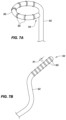
- a plurality of contact force sensing elements 80 can be coupled with the elongated medical device 82 , where a distal end 94 of the elongated medical device 82 can be configured in the shape of a hoop 96 .
- the hoop 96 can be shaped to fit a specific body feature (e.g., the pulmonary vein (PV)).
- PV pulmonary vein
- the elongated medical device 82 can be used for PV isolation (PVI) during ablation procedures.
- the contact force sensing element 80 can be mounted to the exterior wall of the elongated medical device 82 similar to the description above for FIG. 6 B .
- the contact force sensing element 80 can be used to detect the contact force exerted on, for example, the contact force sensors and/or portions of the hoop 96 by tissue. The detected contact forces can be used to, for example, facilitate contact between the PV and the hoop 96 .
- FIG. 7 B is a side view of a contact force sensing element of FIGS. 6 A and 6 B on an elongated medical device with a section of a distal end for linear sensing/detecting and therapy, consistent with embodiments in the present disclosure.
- the plurality of contact force sensing elements 80 can have a width 81 and can be mounted on, for example, an elongated medical device 82 .
- the elongated medical device 82 can be a flexible catheter.
- the distal end 94 of the elongated medical device 82 can be, for example, configured to form a linear configuration of the plurality of contact force sensing elements 80 .
- the linear configuration can facilitate contact of the plurality of contact force sensing elements 80 to contact the tissue 13 .
- the plurality of contact force sensing elements 80 can be used, for example, when lines of ablations are created.
- the flexible catheter can, for example, conform to variations in the shape/profile of tissue to allow the linear configuration to facilitate contact between the plurality of contact force sensing elements 80 and the tissue.
- the plurality of contact force sensing elements 80 can be mounted along a section of the elongated medical device 82 (e.g., at a tip/end location, proximal a distal end, etc.).
- the contact force sensing elements 80 can have, for example, any suitable distance between the contact force sensing elements.
- the spacing between the various contact force sensing elements can be any suitable spacing and can be equal or varied spacing.
- the plurality of contact force sensing elements 80 can be narrower than the embodiment shown in FIGS. 7 B (and 6 A, 6 B, and 7 A) to, for example, accommodate a curvature of the hoop 96 .
- joinder references do not necessarily infer that two elements are directly connected and in fixed relation to each other. It is intended that all matter contained in the above description or shown in the accompanying drawings shall be interpreted as illustrative only and not limiting. Changes in detail or structure can be made without departing from the spirit of the disclosure as defined in the appended claims.
- proximal and distal may be used throughout the specification with reference to a clinician manipulating one end of an instrument used to treat a patient.
- proximal refers to the portion of the instrument closest to the clinician and the term “distal” refers to the portion located furthest from the clinician.
- distal refers to the portion located furthest from the clinician.
- spatial terms such as “vertical,” “horizontal,” “up,” and “down” may be used herein with respect to the illustrated embodiments.
- surgical instruments may be used in many orientations and positions, and these terms are not intended to be limiting and absolute.
Abstract
Description
Claims (29)
Priority Applications (1)
| Application Number | Priority Date | Filing Date | Title |
|---|---|---|---|
| US16/492,208 US11707231B2 (en) | 2017-03-10 | 2018-03-09 | Apparatuses, methods, and systems for contact force sensing |
Applications Claiming Priority (3)
| Application Number | Priority Date | Filing Date | Title |
|---|---|---|---|
| US201762469572P | 2017-03-10 | 2017-03-10 | |
| US16/492,208 US11707231B2 (en) | 2017-03-10 | 2018-03-09 | Apparatuses, methods, and systems for contact force sensing |
| PCT/IB2018/051577 WO2018163129A1 (en) | 2017-03-10 | 2018-03-09 | Apparatuses, methods, and systems for contact force sensing |
Publications (2)
| Publication Number | Publication Date |
|---|---|
| US20200008747A1 US20200008747A1 (en) | 2020-01-09 |
| US11707231B2 true US11707231B2 (en) | 2023-07-25 |
Family
ID=61768360
Family Applications (1)
| Application Number | Title | Priority Date | Filing Date |
|---|---|---|---|
| US16/492,208 Active 2040-08-14 US11707231B2 (en) | 2017-03-10 | 2018-03-09 | Apparatuses, methods, and systems for contact force sensing |
Country Status (2)
| Country | Link |
|---|---|
| US (1) | US11707231B2 (en) |
| WO (1) | WO2018163129A1 (en) |
Citations (4)
| Publication number | Priority date | Publication date | Assignee | Title |
|---|---|---|---|---|
| US20040225298A1 (en) * | 2000-03-23 | 2004-11-11 | Tom Curtis P. | Pressure sensor for therapeutic delivery device and method |
| WO2011022665A1 (en) | 2009-08-21 | 2011-02-24 | Regents Of The University Of Minnesota | Flexible sensors and related systems for determining forces applied to an object, such as a surgical instrument |
| US20140276078A1 (en) * | 2013-03-15 | 2014-09-18 | St. Jude Medical, Atrial Fibrillation Division, Inc. | Electrode contact feedback system |
| US20140364848A1 (en) * | 2011-12-29 | 2014-12-11 | St. Jude Medical, Atrial Fibrillation Division,Inc | System for optimized coupling of ablation catheters to body tissues and evaulation of lesions formed by the catheters |
-
2018
- 2018-03-09 WO PCT/IB2018/051577 patent/WO2018163129A1/en active Application Filing
- 2018-03-09 US US16/492,208 patent/US11707231B2/en active Active
Patent Citations (5)
| Publication number | Priority date | Publication date | Assignee | Title |
|---|---|---|---|---|
| US20040225298A1 (en) * | 2000-03-23 | 2004-11-11 | Tom Curtis P. | Pressure sensor for therapeutic delivery device and method |
| WO2011022665A1 (en) | 2009-08-21 | 2011-02-24 | Regents Of The University Of Minnesota | Flexible sensors and related systems for determining forces applied to an object, such as a surgical instrument |
| US20160076953A1 (en) | 2009-08-21 | 2016-03-17 | Regents Of The University Of Minnesota | Flexible sensors and related systems for determining forces applied to an object, such as a surgical instrument, and methods for manufacturing same |
| US20140364848A1 (en) * | 2011-12-29 | 2014-12-11 | St. Jude Medical, Atrial Fibrillation Division,Inc | System for optimized coupling of ablation catheters to body tissues and evaulation of lesions formed by the catheters |
| US20140276078A1 (en) * | 2013-03-15 | 2014-09-18 | St. Jude Medical, Atrial Fibrillation Division, Inc. | Electrode contact feedback system |
Also Published As
| Publication number | Publication date |
|---|---|
| WO2018163129A1 (en) | 2018-09-13 |
| US20200008747A1 (en) | 2020-01-09 |
Similar Documents
| Publication | Publication Date | Title |
|---|---|---|
| JP6691602B2 (en) | Medical device with multi-core fiber for optical sensing | |
| US8380276B2 (en) | Catheter with thin film pressure sensing distal tip | |
| US10524731B2 (en) | Electrode contact feedback system | |
| US8864757B2 (en) | System and method for measuring force and torque applied to a catheter electrode tip | |
| CN110944591B (en) | Optical force sensing catheter system | |
| US10664008B2 (en) | Catheter-based system having dongle with shape memory | |
| US11707231B2 (en) | Apparatuses, methods, and systems for contact force sensing | |
| EP3998935B1 (en) | Wire management coupler for a medical device | |
| US11420019B2 (en) | Unibody intravascular catheter shaft | |
| US11872026B2 (en) | Catheter contact force sensor |
Legal Events
| Date | Code | Title | Description |
|---|---|---|---|
| FEPP | Fee payment procedure |
Free format text: ENTITY STATUS SET TO UNDISCOUNTED (ORIGINAL EVENT CODE: BIG.); ENTITY STATUS OF PATENT OWNER: LARGE ENTITY |
|
| AS | Assignment |
Owner name: ST. JUDE MEDICAL, CARDIOLOGY DIVISION, INC., MINNESOTA Free format text: ASSIGNMENT OF ASSIGNORS INTEREST;ASSIGNORS:LUPOTTI, FERMIN A.;BLANCK, ARTHUR G.;REEL/FRAME:051049/0421 Effective date: 20180208 Owner name: ST. JUDE MEDICAL, CARDIOLOGY DIVISION, INC., MINNE Free format text: ASSIGNMENT OF ASSIGNORS INTEREST;ASSIGNORS:LUPOTTI, FERMIN A.;BLANCK, ARTHUR G.;REEL/FRAME:051049/0421 Effective date: 20180208 |
|
| STPP | Information on status: patent application and granting procedure in general |
Free format text: DOCKETED NEW CASE - READY FOR EXAMINATION |
|
| STPP | Information on status: patent application and granting procedure in general |
Free format text: NON FINAL ACTION MAILED |
|
| STPP | Information on status: patent application and granting procedure in general |
Free format text: RESPONSE TO NON-FINAL OFFICE ACTION ENTERED AND FORWARDED TO EXAMINER |
|
| STPP | Information on status: patent application and granting procedure in general |
Free format text: FINAL REJECTION MAILED |
|
| STPP | Information on status: patent application and granting procedure in general |
Free format text: PUBLICATIONS -- ISSUE FEE PAYMENT VERIFIED |
|
| STCF | Information on status: patent grant |
Free format text: PATENTED CASE |