EP3756442A1 - Shearbar - Google Patents
Shearbar Download PDFInfo
- Publication number
- EP3756442A1 EP3756442A1 EP20177537.6A EP20177537A EP3756442A1 EP 3756442 A1 EP3756442 A1 EP 3756442A1 EP 20177537 A EP20177537 A EP 20177537A EP 3756442 A1 EP3756442 A1 EP 3756442A1
- Authority
- EP
- European Patent Office
- Prior art keywords
- cutting
- inlet
- cutting edge
- inlet element
- section
- Prior art date
- Legal status (The legal status is an assumption and is not a legal conclusion. Google has not performed a legal analysis and makes no representation as to the accuracy of the status listed.)
- Granted
Links
- 230000007704 transition Effects 0.000 claims abstract description 50
- 239000000463 material Substances 0.000 claims abstract description 19
- 238000000034 method Methods 0.000 claims abstract description 9
- 238000005245 sintering Methods 0.000 claims abstract description 8
- 239000004459 forage Substances 0.000 claims abstract description 5
- 239000002184 metal Substances 0.000 claims description 9
- 238000004519 manufacturing process Methods 0.000 abstract description 4
- 238000010276 construction Methods 0.000 description 7
- 239000000919 ceramic Substances 0.000 description 4
- 238000000227 grinding Methods 0.000 description 3
- 239000000853 adhesive Substances 0.000 description 2
- 230000001070 adhesive effect Effects 0.000 description 2
- 229910000831 Steel Inorganic materials 0.000 description 1
- 230000002411 adverse Effects 0.000 description 1
- 229910010293 ceramic material Inorganic materials 0.000 description 1
- 238000003801 milling Methods 0.000 description 1
- 230000035939 shock Effects 0.000 description 1
- 239000010959 steel Substances 0.000 description 1
- 238000011144 upstream manufacturing Methods 0.000 description 1
- 239000002023 wood Substances 0.000 description 1
Images


Classifications
-
- A—HUMAN NECESSITIES
- A01—AGRICULTURE; FORESTRY; ANIMAL HUSBANDRY; HUNTING; TRAPPING; FISHING
- A01D—HARVESTING; MOWING
- A01D34/00—Mowers; Mowing apparatus of harvesters
- A01D34/01—Mowers; Mowing apparatus of harvesters characterised by features relating to the type of cutting apparatus
- A01D34/412—Mowers; Mowing apparatus of harvesters characterised by features relating to the type of cutting apparatus having rotating cutters
- A01D34/42—Mowers; Mowing apparatus of harvesters characterised by features relating to the type of cutting apparatus having rotating cutters having cutters rotating about a horizontal axis, e.g. cutting-cylinders
- A01D34/52—Cutting apparatus
-
- A—HUMAN NECESSITIES
- A01—AGRICULTURE; FORESTRY; ANIMAL HUSBANDRY; HUNTING; TRAPPING; FISHING
- A01D—HARVESTING; MOWING
- A01D43/00—Mowers combined with apparatus performing additional operations while mowing
- A01D43/08—Mowers combined with apparatus performing additional operations while mowing with means for cutting up the mown crop, e.g. forage harvesters
-
- A—HUMAN NECESSITIES
- A01—AGRICULTURE; FORESTRY; ANIMAL HUSBANDRY; HUNTING; TRAPPING; FISHING
- A01F—PROCESSING OF HARVESTED PRODUCE; HAY OR STRAW PRESSES; DEVICES FOR STORING AGRICULTURAL OR HORTICULTURAL PRODUCE
- A01F29/00—Cutting apparatus specially adapted for cutting hay, straw or the like
- A01F29/06—Cutting apparatus specially adapted for cutting hay, straw or the like having rotating knives with their cutting edges on a cylinder surface, e.g. of the helical-type
-
- A—HUMAN NECESSITIES
- A01—AGRICULTURE; FORESTRY; ANIMAL HUSBANDRY; HUNTING; TRAPPING; FISHING
- A01F—PROCESSING OF HARVESTED PRODUCE; HAY OR STRAW PRESSES; DEVICES FOR STORING AGRICULTURAL OR HORTICULTURAL PRODUCE
- A01F29/00—Cutting apparatus specially adapted for cutting hay, straw or the like
- A01F29/09—Details
-
- B—PERFORMING OPERATIONS; TRANSPORTING
- B02—CRUSHING, PULVERISING, OR DISINTEGRATING; PREPARATORY TREATMENT OF GRAIN FOR MILLING
- B02C—CRUSHING, PULVERISING, OR DISINTEGRATING IN GENERAL; MILLING GRAIN
- B02C18/00—Disintegrating by knives or other cutting or tearing members which chop material into fragments
- B02C18/06—Disintegrating by knives or other cutting or tearing members which chop material into fragments with rotating knives
- B02C18/16—Details
- B02C18/18—Knives; Mountings thereof
- B02C2018/188—Stationary counter-knives; Mountings thereof
Definitions
- the invention relates to a shearbar, in particular for a forage harvester or some other agricultural or forestry machine, with a carrier that has a cutting area, a plurality of cutting elements being lined up in the cutting area, the cutting elements having a partial cutting edge and at least one part the partial cutting form a cutting edge which is designed to form a cutting engagement for the material to be comminuted with a knife strip, the cutting edge being a transition between a cutting surface formed by the cutting elements and extending transversely to the cutting direction and a substantially in Forms a free surface extending in the cutting direction and directly or indirectly connected to the cutting edge,
- a shearbar which is intended for use in a forage harvester or a wood chopper.
- the shearbar has a support body on which is equipped with cutting elements on opposite sides.
- the cutting elements each have a partial cutting edge.
- the partial cutting edges form a common cutting edge. If a cutting edge is worn out, the counter blade can be reattached in an arrangement rotated by 180 ° so that the second cutting edge is used.
- an inlet element is provided on or in the row of cutting elements, which is designed as a sintered part, consisting of hard material with an inlet chamfer profiled in the sintering process, the inlet chamfer being transferred directly or indirectly to the cutting edge, and the inlet chamfer is arranged at an angle to the cutting edge that it is arranged set back in relation to the free surface and in the direction of the cutting surface.
- the inlet element according to the invention prevents a cutting edge breakage from being prevented even if the cutting gap is not set exactly.
- the knife strip can run into the inlet chamfer of the inlet element which is set back. In this operating phase, the knife strip will not touch down hard on the anvil if the cutting gap is incorrectly set.
- the male connector slides on the inlet chamfer and can be deflected elastically in the radial direction. This is possible, for example, due to the inherent elasticity of the male connector or by an elastic deflection device.
- the cutting edge of the knife bar comes into the region of the cutting edge of the counter-knife, since according to the invention the lead-in bevel is transferred into the cutting edge.
- the inlet element which consists of a hard material, for example ceramic or hard metal, is provided with the inlet bevel that has already been profiled in the sintering process.
- the inlet element is first pressed with the inlet bevel as a green compact.
- the green compact is then fired in the sintering furnace.
- the inlet element can then be used immediately and can be built into the counter blade, for example soldered or glued. In this way, there is no need for a complex grinding process in which the run-in chamfer is ground. In particular, this step is not only costly.
- thermal energy would be introduced into the already manufactured anvil by means of the grinding process via the inlet element into the connection point between the inlet element and the support body of the anvil.
- This changes the structure of the connecting material soldered connection, adhesive connection, etc.
- the depth of the pressed-in run-in chamfer perpendicular to the free surface of the adjoining cutting element is in the range between 0.5 and 1.8 mm. At such a depth, the misalignments that usually occur during operation, especially changes in the position of the knife edges that occur during operation, are taken into account in an optimized manner.
- the inlet element has a cutting edge section with an inlet element cutting edge, and this inlet element cutting edge merges into the cutting edge formed by the cutting elements, in particular being in alignment with this cutting edge.
- the run-in bevel can be transferred directly to the run-in element cutting edge formed there directly on the run-in element. With the selected manufacturing process in the sintering process, this can be carried out easily and with high dimensional accuracy.
- the knife strip can accordingly run up against the lead-in bevel and be transferred into the lead-in element cutting edge. The knife edge is then in a position in which it can no longer damage the subsequent cutting edge.
- the inlet element has a cover section which merges flush into the cutting surface formed by the adjacent cutting element, then a step-free transition is created which enables a good and low-wear transition of the knife strip into the area of the cutting edge.
- the inlet element has a front-side inlet element free surface which merges flush into the free surface formed by the adjacent cutting element.
- the inlet bevel of the inlet element is delimited on opposite sides by an edge and a transition section, the edge merging into a top-side cover section and the transition section transferring the inlet chamfer into the inlet element open area.
- the lead-in bevel is inclined to the cutting edge in such a way that the approaching knife edge can neither touch down directly on the cover section nor on the free surface if the cutting gap is not precisely maintained.
- the inlet element has a central longitudinal plane extending in the direction of the cutting edge and a central transverse plane which is perpendicular to it and also extends in the direction of the cutting edge, so that the inlet chamfer or chamfers both to the central longitudinal plane and to the The central transverse plane is at an angle or that the inlet bevel or chamfers is at an angle to the central longitudinal plane.
- the inlet element has a joint at its one longitudinal end, in the transition area to the adjoining cutting element, and an end section at the opposite longitudinal end that, following the inlet chamfer, a second transition area in the area of the end section is provided, which adjoins the inlet chamfer flat and at an angle and / or curved.
- the inlet element can preferably connect to the adjoining cutting element of the row of cutting elements without a gap via the joint. In this way, the transition area between the inlet element and the adjoining cutting element is protected from abrasive attack, which leads to an extended service life.
- the knife edge running up on the inlet element can be transferred directly and gently into the cutting element.
- the second transition area which is provided on the end section, can also be designed in a suitable manner for this purpose.
- the inlet element there is a simple and stable structure if it is provided that the inlet element is delimited on its upper side by a cover section and its underside by a floor, the cover section preferably being parallel to the floor, that the inlet element is at the front from the The inlet element open area is limited and that the inlet element open area adjoins the cover section and / or the floor.
- an inlet element is provided at a longitudinal end of the row of cutting elements.
- Such a construction is useful, for example, when the knife edges of the chopping drum extend over the entire cutting width of the chopping drum, the knife edges being set at an angle of less than 90 ° to the direction of rotation (cutting direction) of the milling drum.
- knife edges are applied on the circumferential side of the chopping drum at the opposite longitudinal ends of the chopping drum, these knife edges each extending at an angle of less than 90 ° to the circumferential direction and the knife edges on the opposite sides being set at an angle to one another, it can preferably be provided be that an inlet element is arranged at the two longitudinal ends of the row of cutting elements. The knife edges at the opposite ends of the chopping drum can then run onto the inlet element assigned to it.
- a construction is also conceivable in which the shearbar is designed such that at least one inlet element is integrated into the row of cutting elements between two adjacent cutting elements.
- This construction is suitable if, for example, in addition to the circumferential rows of knife edges, which are provided at the two opposite ends of the chopping drum, one or more rows of cutting elements are also used in the center of the chopping drum between the two ends.
- the inlet element can preferably have two inlet chamfers which are at an angle to one another and to the cutting edge, and that the inlet chamfers merge into one another directly or via a connecting section.
- the two rows of knife edges can run onto the common inlet element, the knife edges of one row running onto the first inlet bevel and the knife edges of the second row on the second inlet bevel. This can further reduce the number of parts.
- an inlet element is integrated into the row of cutting elements for each row of knife edges.
- the two inlet elements can then, for example, be placed directly next to one another or at a distance from one another.
- the two inlet elements can be constructed mirror-symmetrically.
- the connecting section terminates with a connecting edge in the region of the cover section, the connecting edge forming a transition between the connecting section and the cover section.
- the connecting section can have a flat surface section or a concavely curved surface section between the two inlet chamfers. In the case of a concave curvature, the connecting section can offer a harmonious transition into the two inlet chamfers. This also enables a stress-optimized design.
- the carrier has rows of cutting elements on opposite sides, each of which forms a cutting edge, and that each of the rows of cutting elements has at least one inlet element, then the shearbar can be installed so that either one of the two Cutting edges comes into cutting engagement with the chopping drum.
- the counter blade can simply be rotated and the second cutting edge brought into cutting engagement. This results in a longer service life and a reduction in the number of parts, since only one carrier has to be used for two cutting edges.
- the row of cutting elements in the area of the upper side of the carrier is followed by a row of armor elements, which are preferably plate-shaped elements made of hard material, in particular Hard metal are formed.
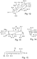
- Figure 1 shows a chopping drum 10 which has a cylindrical cutting body 11. Blade strips 13 are arranged on the outer circumference of the cutting body 11. The knife strips 13 each have a cutting edge 14. The knife strips 13 are applied to the outer circumference of the cutting body 11 so that that they are employed at a cutting angle ⁇ .
- the cutting angle ⁇ is formed between the cutting edge 14 and an axial line running parallel to the axis of rotation of the chopping drum 10.
- the arrangement of the blade strips 13 is such that the blade strips 13 of one row of blade strips 13 are positioned in a V-shape relative to the other row of blade strips 13.
- the same cutting angles ⁇ are provided in each case.
- the cutting body 11 has bearing shafts 12 at both of its longitudinal ends. With these it can be held rotatably on a cutting unit.
- the Figures 1 and 2 further show that a shearbar 20 is provided.
- the shearbar 20 forms a cutting edge 32.
- the chopping drum 10 is assigned to the shearbar 20 in such a way that when the chopping drum 10 rotates, the knife strips 13 with their blades 14 can be guided past the cutting edge 32 at a close distance. This is in the Figures 3 and 4 illustrated in more detail.
- the counter blade 20 has a carrier 21.
- This carrier 21 is formed from a steel material.
- the carrier 21 has end pieces 22 at both of its longitudinal ends.
- the end pieces 22 are equipped with fastening receptacles 23, for example fastening bores. With the fastening receptacles 23, the anvil 20 can be detachably fastened in the region of the cutting unit.
- the anvil 20 has two cutting areas 30.
- the cutting areas 30 are provided on the opposite longitudinal sides of the carrier 21.
- a row of cutting elements 31 is provided in each cutting area 30.
- the cutting elements 31 are made of hard material elements, for example elements made of hard metal or ceramic.
- the cutting elements 31 essentially have a cuboid construction.
- the cutting elements 31 are assigned to the carrier 21 in such a way that their narrow sides sit on a contact surface of the carrier 21.
- the rear side of the cutting elements 31 is supported against a support surface of the carrier 21.
- a soldered connection can be provided in the area of the rear sides and the contact area.
- Another material connection for example an adhesive connection, is also conceivable.
- the side of the cutting elements 31 opposite the contact surface forms a cutting surface 32.1.
- the free-standing edge of this cutting surface 32.1 in each case forms a partial cutting edge.
- the partial cutting edge correspondingly forms a transition between the cutting surface 32.1 and a free surface 32.2 adjoining it in the cutting direction.
- the cutting elements 31 are lined up in a row with no spacing via joints 33. This results in a continuous cutting edge 32 in the cutting area 30.
- two cutting edges 32 are provided on opposite sides of the carrier 21 in the two cutting areas 30.
- the armor elements 35 can also consist of hard material, for example hard metal or ceramic. They are materially connected to the upper side of the carrier 21, for example glued or soldered. The armor elements 35 are preferably attached to one another without any spacing at their longitudinal ends 35.1. In this way, the joints between the armor elements 35 are also protected from being washed out.
- the Figures 3 and 4 further show that inlet elements 34 are provided at the longitudinal end of the two rows of cutting elements 31.
- the inlet elements 34 like the cutting elements 31, consist of a hard material, in particular of hard metal or ceramic material.
- the inlet elements 34 are sintered components that are placed in an upstream Process step manufactured separately and then connected to the counter blade 20, for example glued or soldered.
- the inlet elements 34 can have a cutting edge section 34.1, this cutting edge section 34.1 then preferably merging into the cutting edge 32 of the cutting element 31.
- This cutting edge section 34.1 is particularly preferably in alignment with the cutting edge 32.
- the inlet element 34 also has an inlet chamfer 34.6.
- the inlet bevel 34.6 can be designed as a flat surface or as a concave surface. Other other geometries are also conceivable, for example convex inlet chamfers or combinations of the aforementioned geometries. However, flat or concave inlet chamfers 34.6 are particularly preferably used.
- the inlet element 34 has a front inlet element open area 34.5. This preferably merges into the free surface 32.2 of the adjoining cutting element 31 without a step. like this the Figures 3 and 4 demonstrate
- the inlet element 34 is closed with a cover section 34.12.
- This cover section 34.12 preferably merges into the cutting surface 32.1 of the adjoining cutting element 31 without a step.
- the cutting edge section 34.1 of the inlet element 34 can form a transition between the cover section 34.12 and the inlet element open surface 34.5 in some areas.
- the inlet element 34 has an inlet chamfer 34.6.
- This lead-in bevel 34.6 is delimited on opposite sides by an edge 34.2 and a transition section 34.3.
- the edge 34.2 forms a transition between the inlet bevel 34.6 and the cover section 34.12.
- the transition section 34.3 forms a transition between the inlet bevel 34.6 and the inlet element free surface 34.5.
- the inlet bevel 34.6 is arranged both at an angle to the inlet element free surface 34.5 and at an angle to the cover section 34.12. This results in particular from the Figures 10 and 11 .
- These drawings show that the inlet chamfer 34.6 both relative to the central longitudinal plane ML (see FIG Figure 11 ) as well as to the central transverse plane MQ, which also runs in the longitudinal direction (see Figure 10 ) is inclined. Due to this inclined arrangement, the lead-in bevel 34.6 is inclined in such a way that it is arranged set back with respect to the cutting edge 32.
- the inlet element free surface 34.5 has a flat joint 34.9 on its side facing the adjoining cutting element 31. With this joint 34.9, the inlet element 34 can be lined up with the adjoining cutting element 31 without a gap.
- the inlet chamfer 34.6 has transition areas 34.7, 34.8 at its two longitudinal ends.
- the design of these transition areas 34.7, 34.8 results from Figure 11 .
- the transition areas 34.7, 34.8 can be designed as flat surfaces which adjoin the inlet chamfer 34.6 at an angle. It is also conceivable to provide an arcuate design at the transition areas 34.7, 34.8. In this way, a harmonious transition to the adjoining areas of the inlet element 34 can be created.
- the transition area 34.7 facing the joint 34.9 is designed as a concave surface.
- the second transition area 34.8 is designed in the form of a flat surface which adjoins the planar inlet chamfer 34.6 at an angle.
- the inlet element 34 Opposite the cover section 34.12, the inlet element 34 has a bottom 34.10 and a rear wall 34.13 at the rear.
- the inlet element 34 is connected to the bottom 34.10 and the rear wall 34.13 by means of a material bond Connection supported on the carrier 21.
- the cohesive connection has a lower modulus of elasticity than the inlet element 34. In this way, the cohesive connection forms a buffer layer, via which shock loads can be absorbed within certain limits.
- the intermediary material connection serves to support the inlet element 34 flat in the area of the base 34.10 and the rear wall 34.13, so that the risk of breakage for the inlet element is significantly reduced.
- the inlet element 34 can also be equipped with a contact area 34.11.
- the contact area 34.11 is formed as a convex wall section. With this wall section, the inlet element 34 can also be materially connected to the carrier 21.
- the contact area 34.11 merges into the transition area 34.8 via a connecting section 34.4.
- the connecting section 34.4 is designed as an arcuate edge.
- the inlet element 34 is preferably made of hard metal. According to the invention, it is designed in such a way that the run-in bevel 34.6 has already been profiled in the sintering process. In this way, there is no need for a complex grinding process for the hard material.
- a green compact with a pressed-on inlet bevel 34.6 is accordingly first produced and this is then baked in the sintering furnace to form the finished hard metal component under the influence of temperature.
- an inlet element 34 is shown in the Figures 12 to 15 .
- This inlet element 34 is constructed essentially similarly to the inlet element 34 according to FIGS Figures 8 to 11 , which is why reference can be made to the above explanations to avoid repetitions.
- the inlet element 34 differs in that the contact area 34.11 is not curved in a convex manner, but is designed in a straight line. In particular, it can be the case that the contact area 34.11 is parallel to the wall which forms the joint 34.9.
- the inlet chamfer 34.6 only has the transition area 34.8.
- the lead-in bevel has no transition area. Rather, it is the case here that the run-in bevel 34.6 extends significantly further in the longitudinal direction, so that the cutting edge section 34.1 is shorter than in the exemplary embodiment according to FIGS Figures 8 to 11 .
- the end section 34.4 is now designed in the form of a vertical straight edge which is in the transition between the contact area 34.11 and the transition area 34.8.
- the inlet chamfer 34.6 is designed so that it is only at an angle to the central longitudinal plane ML. Employment at the central transverse level MQ is not intended here. Accordingly, the run-in bevel 34.6 is inclined only in one plane. This results in a vertically running transition section 34.3. In contrast to this, in the case of the inlet elements 34.6 described above, inclined transition sections 34.3 are provided.
- FIGS Figures 19 to 21 a further embodiment of a shearbar 20 is described.
- This shearbar 20 basically has the same overall structure as the shearbar 20 according to FIGS Figures 5 to 7 . In this respect, only the differences will be discussed.
- a carrier 21 with end pieces 22 and Fastening receptacles 23 are provided.
- inlet elements 34 are provided at the longitudinal ends of the cutting edges 32. This is also the case with the anvil 20 according to FIGS Figures 18 to 21 the case. In addition, however, the shearbar according to the Figures 18 to 21 also inlet elements 34 which are lined up in the rows of cutting elements 31. Two additional inlet elements of FIG. 34 are provided for each cutting edge 32.
- the inlet elements 34 have cutting edge sections 34.1 on opposite sides.
- the cutting edge sections 34.1 form a transition between a front inlet element free surface 34.5 and a cover section 34.12.
- Inlet chamfers 34.6 are provided next to the two cutting edge sections 34.1.
- the inlet chamfers 34.6 are delimited on opposite sides by an edge 34.2 and a transition section 34.3.
- the design of the inlet element 34 corresponds to the prescribed design of the inlet elements 34 and all the variants that have been described above can also be used with respect to the inlet element 34 according to FIGS Figures 22 to 25 be executed.
- the inlet element has two inlet chamfers 34.6, which are arranged inclined to one another.
- the inlet chamfers 34.6 are connected to one another via a connecting section 34.14.
- the connecting section 34.14 can, as Figure 22 shows be designed as a concave bulge. However, a two-dimensional, planar configuration of the connecting section 34.14, such as Figure 26 shows. Both connecting sections 34.14 are connected in the middle via the connecting edge 34.15.
- the connecting edge 34.15 creates a transition from the cover section 34.12 to the connecting section 34.14.
- the two lead-in chamfers 34.6 can also, as described above, be provided with one or two transition regions 34.7, 34.8 at the longitudinal ends.
- these inlet elements 34 are integrated into the row of cutting elements 31 in such a way that a cutting element 31 is directly connected on each side.
- the cutting edge sections 34.1 then both merge into the subsequent cutting edge 32.
- the inlet element free surface 34.5 and the cover section 34.12 can each merge into the adjoining free areas 32.2 or the adjoining cutting surfaces 32.1 of the adjacent cutting elements 31 without a step.
- the counter blades 20 in the construction according to Figures 19 to 21 can be used in chopping drums 10, where in addition to the side rows of knife strips 13, as they are in the Figures 1 and 2 are shown, between these two blade strips 13 still further circumferential rows of blade strips are provided. These male connectors 13 are then again inclined (angle a).
- the inlet element 34 according to Figure 27 shows in contrast to the inlet element 34 according to FIG Figure 26 no transition area 34.7. Furthermore, the inlet bevel 34.6 is designed differently, the inlet bevel 34.6 extending over a further area of the inlet element free surface 34.5 and correspondingly the transition section 34.6 being inclined more steeply.
- the inlet element 34 With the inlet element 34 according to Figure 28 two transition areas 34.7, 34.8 are provided.
- the inlet chamfers 34.6 are each arranged inclined only in the direction of the central longitudinal plane ML and not in the direction of the central transverse plane MQ.
Abstract
Die Erfindung betrifft eine Gegenschneide (20), insbesondere für einen Feldhäcksler oder eine sonstige land- oder forstwirtschaftliche Maschine, mit einem Träger (21) der einen Schneidbereich (30) aufweist, wobei im Schneidbereich (30) eine Vielzahl von Schneidelementen (31), aneinandergereiht sind, wobei die Schneidelemente (31) eine Teil-Schneide aufweisen und zumindest ein Teil der Teil-Schneiden eine Schneidkante (32) bilden, die ausgebildet ist, um mit einer Messerleiste einen Schneideingriff für das zu zerkleinernde Material zu bilden, wobei die Schneidkante (32) einen Übergang zwischen einer von den Schneidelementen (31) gebildeten und sich quer zur Schneidrichtung erstreckenden Schneidfläche (32.1) und einer sich im Wesentlichen in Schneidrichtung erstreckenden, an die Schneidkante (32) mittelbar oder unmittelbar anschließenden Freifläche (32.2) bildet. Eine solche Gegenschneide kann dann bruchstabil mit geringem Teile- und Fertigungsaufwand gestaltet werden, wenn vorgesehen ist, dass an oder in der Reihe von Schneidelementen (31) ein Einlaufelement (34) vorgesehen ist, das als Sinterteil, bestehend aus Hartwerkstoff mit im Sinterverfahren anprofilierter Einlauffase (34.6) ausgebildet ist, wobei die Einlauffase (34.6) in die Schneidkante (32) mittelbar oder unmittelbar übergeleitet ist, und wobei die Einlauffase (34.6) derart geneigt zu der Schneidkante (32) angeordnet ist, dass sie gegenüber der Freifläche (32.2) und in Richtung der Schneidfläche (32.1) zurückversetzt angeordnet ist.The invention relates to a shearbar (20), in particular for a forage harvester or some other agricultural or forestry machine, with a carrier (21) which has a cutting area (30), a plurality of cutting elements (31), in the cutting area (30), are strung together, the cutting elements (31) having a partial cutting edge and at least some of the partial cutting edges forming a cutting edge (32) which is designed to form a cutting engagement with a knife bar for the material to be shredded, the cutting edge (32) forms a transition between a cutting surface (32.1) formed by the cutting elements (31) and extending transversely to the cutting direction and a free surface (32.2) extending essentially in the cutting direction and directly or indirectly connected to the cutting edge (32). Such a shearbar can then be designed to be break-resistant with low parts and manufacturing costs if it is provided that an inlet element (34) is provided on or in the row of cutting elements (31), which is a sintered part made of hard material with an inlet bevel profiled in the sintering process (34.6), the lead-in bevel (34.6) being transferred directly or indirectly into the cutting edge (32), and the lead-in bevel (34.6) being inclined to the cutting edge (32) in such a way that it is opposite to the free surface (32.2) and is arranged set back in the direction of the cutting surface (32.1).
Description
Die Erfindung betrifft eine Gegenschneide, insbesondere für einen Feldhäcksler oder eine sonstige land- oder forstwirtschaftliche Maschine, mit einem Träger der einen Schneidbereich aufweist, wobei im Schneidbereich eine Vielzahl von Schneidelementen, aneinandergereiht sind, wobei die Schneidelemente eine Teil-Schneide aufweisen und zumindest ein Teil der Teil-Schneiden eine Schneidkante bilden, die ausgebildet ist, um mit einer Messerleiste einen Schneideingriff für das zu zerkleinernde Material zu bilden, wobei die Schneidkante einen Übergang zwischen einer von den Schneidelementen gebildeten und sich quer zur Schneidrichtung erstreckenden Schneidfläche und einer sich im Wesentlichen in Schneidrichtung erstreckenden, an die Schneidkante mittelbar oder unmittelbar anschließenden Freifläche bildet,The invention relates to a shearbar, in particular for a forage harvester or some other agricultural or forestry machine, with a carrier that has a cutting area, a plurality of cutting elements being lined up in the cutting area, the cutting elements having a partial cutting edge and at least one part the partial cutting form a cutting edge which is designed to form a cutting engagement for the material to be comminuted with a knife strip, the cutting edge being a transition between a cutting surface formed by the cutting elements and extending transversely to the cutting direction and a substantially in Forms a free surface extending in the cutting direction and directly or indirectly connected to the cutting edge,
Aus der
Um eine gute Schneidleistung zu erreichen, ist es erforderlich den Schneidspalt zwischen der Gegenschneide und den Messerleisten so klein wie möglich einstellen zu können. Dabei ist allerdings darauf zu achten, dass ein Aufsetzen der Messerleisten auf den Gegenschneiden verhindert ist. Bei einem solchen Kontakt besteht die Gefahr, dass die aus einem sprödbrüchigen Hartwerkstoff (beispielsweise Hartmetall oder Keramik) bestehenden Schneidelemente beschädigt werden. Bei einer so beschädigten Gegenschneide sinkt die Schneidleistung erheblich und ein vorzeitiger Austausch ist erforderlich, um die gewünschte Schneidleistung aufrechtzuerhalten. Die Einstellung der Gegenschneide erfordert Know-how und eine präzise arbeitende Einstellvorrichtung. Es ist nicht immer auszuschließen, dass der Schneidspalt nicht exakt eingestellt wird oder sich im Laufe der Betriebszeit die Gegenschneide ungewollt verstellt.In order to achieve good cutting performance, it is necessary to be able to set the cutting gap between the counter blade and the knife strips as small as possible. However, it is important to ensure that the knife strips do not touch the counter blades. In the event of such contact, there is a risk that the cutting elements made of a brittle hard material (for example hard metal or ceramic) will be damaged. If the shearbar is damaged in this way, the cutting performance is significantly reduced and early replacement is required in order to maintain the desired cutting performance. The adjustment of the shearbar requires know-how and a precise adjustment device. It cannot always be ruled out that the cutting gap is not set exactly or that the anvil shifts inadvertently during the operating time.
Aus
Es ist Aufgabe der Erfindung, eine Gegenschneide der eingangs erwähnten Art bereitzustellen, bei der mit geringem Teile und Fertigungsaufwand ein Schneidenbruch auch dann zuverlässig verhindert ist, wenn der Schneidspalt nicht exakt eingehalten ist.It is the object of the invention to provide a shearbar of the type mentioned at the outset, in which, with a small amount of parts and manufacturing expense, a cutter breakage is reliably prevented even if the cutting gap is not precisely maintained.
Diese Aufgabe wird dadurch gelöst, dass an oder in der Reihe von Schneidelementen ein Einlaufelement vorgesehen ist, das als Sinterteil, bestehend aus Hartwerkstoff mit im Sinterverfahren anprofilierter Einlauffase ausgebildet ist, wobei die Einlauffase in die Schneidkante mittelbar oder unmittelbar übergeleitet ist, und wobei die Einlauffase derart im Winkel zu der Schneidkante angeordnet ist, dass sie gegenüber der Freifläche und in Richtung der Schneidfläche zurückversetzt angeordnet ist.This object is achieved in that an inlet element is provided on or in the row of cutting elements, which is designed as a sintered part, consisting of hard material with an inlet chamfer profiled in the sintering process, the inlet chamfer being transferred directly or indirectly to the cutting edge, and the inlet chamfer is arranged at an angle to the cutting edge that it is arranged set back in relation to the free surface and in the direction of the cutting surface.
Mit dem erfindungsgemäßen Einlaufelement ist verhindert, dass auch dann, wenn der Schneidspalt nicht exakt eingestellt ist, ein Schneidenbruch verhindert ist. Insbesondere kann die Messerleiste bei zu klein eingestelltem Schneidspalt an der zurückversetzt angeordneten Einlauffase des Einlaufelements auflaufen. In dieser Betriebsphase ist dann ein hartes Aufsetzen der Messerleiste auf der Gegenschneide bei fehlerhaft eingestelltem Schneidspalt ausgeschlossen. Die Messerleiste gleitet an der Einlauffase auf und kann elastisch in radialer Richtung ausgelenkt werden. Dies ist beispielsweise aufgrund der Eigenelastizität der Messerleiste oder durch eine elastische Auslenkvorrichtung möglich. Wenn die Messerleiste die Einlauffase passiert hat, so gelangt die Schneide der Messerleiste in den Bereich der Schneidkante der Gegenschneide, da die Einlauffase erfindungsgemäß in die Schneidkante übergeleitet ist.The inlet element according to the invention prevents a cutting edge breakage from being prevented even if the cutting gap is not set exactly. In particular, if the cutting gap is set too small, the knife strip can run into the inlet chamfer of the inlet element which is set back. In this operating phase, the knife strip will not touch down hard on the anvil if the cutting gap is incorrectly set. The male connector slides on the inlet chamfer and can be deflected elastically in the radial direction. This is possible, for example, due to the inherent elasticity of the male connector or by an elastic deflection device. When the knife bar has passed the lead-in bevel, the cutting edge of the knife bar comes into the region of the cutting edge of the counter-knife, since according to the invention the lead-in bevel is transferred into the cutting edge.
Es stellt nun eine Besonderheit der Erfindung dar, dass das Einlaufelement, welches aus einem Hartwerkstoff, beispielsweise Keramik oder Hartmetall, besteht mit der im Sinterverfahren bereits anprofilierten Einlauffase versehen ist. Mit anderen Worten wird während des Fertigungsprozesses das Einlaufelement zunächst mit der Einlauffase als Grünling gepresst. Anschließend wird der Grünling im Sinterofen gebrannt. Das Einlaufelement ist dann unmittelbar verwendbar und kann mit der Gegenschneide verbaut, beispielsweise verlötet oder verklebt, werden. Auf diese Weise kann auf einen aufwändigen Schleifprozess, bei dem die Einlauffase geschliffen wird, verzichtet werden. Insbesondere ist dieser Schritt nicht nur kostenintensiv. Vielmehr würde in die bereits gefertigte Gegenschneide mittels des Schleifprozesses Wärmeenergie über das Einlaufelement in die Verbindungsstelle zwischen Einlaufelement und dem Tragkörper der Gegenschneide eingebracht. Hierdurch verändert sich das Gefüge des Verbindungsmaterials (Lötverbindung, Klebeverbindung etc.), wodurch die Festigkeit nachteilig beeinträchtigt werden kann.It is a special feature of the invention that the inlet element, which consists of a hard material, for example ceramic or hard metal, is provided with the inlet bevel that has already been profiled in the sintering process. In other words, during the manufacturing process, the inlet element is first pressed with the inlet bevel as a green compact. The green compact is then fired in the sintering furnace. The inlet element can then be used immediately and can be built into the counter blade, for example soldered or glued. In this way, there is no need for a complex grinding process in which the run-in chamfer is ground. In particular, this step is not only costly. Rather, thermal energy would be introduced into the already manufactured anvil by means of the grinding process via the inlet element into the connection point between the inlet element and the support body of the anvil. This changes the structure of the connecting material (soldered connection, adhesive connection, etc.), which can adversely affect the strength.
Besonders bevorzugt ist es vorgesehen, dass die Tiefe der eingepressten Einlauffase senkrecht zur Freifläche des anschließenden Schneidelements im Bereich zwischen 0,5 und 1,8 mm beträgt. Bei einer solchen Tiefe wird den im Betrieb üblicherweise auftretenden Fehlstellungen, insbesondere während des Betriebseinsatzes auftretenden Veränderungen in der Stellung der Messerschneiden in optimierter Weise Rechnung getragen.It is particularly preferably provided that the depth of the pressed-in run-in chamfer perpendicular to the free surface of the adjoining cutting element is in the range between 0.5 and 1.8 mm. At such a depth, the misalignments that usually occur during operation, especially changes in the position of the knife edges that occur during operation, are taken into account in an optimized manner.
Gemäß einer bevorzugten Erfindungsvariante kann es vorgesehen sein, dass das Einlaufelement einen Schneidenabschnitt mit einer Einlaufelement-Schneidkante aufweist, und wobei diese Einlaufelement-Schneidkante in die von den Schneidelementen gebildete Schneidkante übergeht, insbesondere in Flucht zu dieser Schneidkante steht. Bei einer solchen Konstruktion kann die Einlauffase unmittelbar am Einlaufelement bereits in die dort gebildete Einlaufelement-Schneidkante übergeleitet werden. Dies ist bei dem gewählten Fertigungsverfahren im Sinterprozess einfach und mit hoher Maßhaltigkeit durchführbar. Die Messerleiste kann dementsprechend auf der Einlauffase auflaufen und in die Einlaufelement-Schneidkante überführt werden. Anschließend steht die Messerschneide in einer Position, in der sie die anschließende Schneidkante nicht mehr beschädigen kann.According to a preferred variant of the invention, it can be provided that the inlet element has a cutting edge section with an inlet element cutting edge, and this inlet element cutting edge merges into the cutting edge formed by the cutting elements, in particular being in alignment with this cutting edge. With such a construction, the run-in bevel can be transferred directly to the run-in element cutting edge formed there directly on the run-in element. With the selected manufacturing process in the sintering process, this can be carried out easily and with high dimensional accuracy. The knife strip can accordingly run up against the lead-in bevel and be transferred into the lead-in element cutting edge. The knife edge is then in a position in which it can no longer damage the subsequent cutting edge.
Wenn vorgesehen ist, dass das Einlaufelement einen Deckabschnitt aufweist, welcher bündig in die von dem benachbarten Schneidelement gebildete Schneidfläche übergeht, dann wird ein absatzloser Übergang geschaffen, der eine gute und verschleißarme Überleitung der Messerleiste in den Bereich der Schneidkante ermöglicht.If it is provided that the inlet element has a cover section which merges flush into the cutting surface formed by the adjacent cutting element, then a step-free transition is created which enables a good and low-wear transition of the knife strip into the area of the cutting edge.
Zu diesem Zweck kann es auch zusätzlich oder alternativ vorgesehen sein, dass das Einlaufelement eine frontseitige Einlaufelement-Freifläche aufweist, die bündig in die von dem benachbarten Schneidelement gebildete Freifläche übergeht.For this purpose, it can additionally or alternatively be provided that the inlet element has a front-side inlet element free surface which merges flush into the free surface formed by the adjacent cutting element.
Gemäß einer denkbaren Erfindungsvariante kann es vorgesehen sein, dass die Einlauffase des Einlaufelements an gegenüberliegenden Seiten von einer Kante und einem Übergangsabschnitt begrenzt ist, wobei die Kante in einen oberseitigen Deckabschnitt übergeht und der Übergangsabschnitt die Einlauffase in die Einlaufelement-Freifläche überleitet. Durch diese einfache Maßnahme wird die Einlauffase derart geneigt zu der Schneidkante angestellt, dass die auflaufende Messerschneide weder unmittelbar auf dem Deckabschnitt noch auf der Freifläche aufsetzen kann, wenn der Schneidspalt nicht exakt eingehalten ist.According to a conceivable variant of the invention, it can be provided that the inlet bevel of the inlet element is delimited on opposite sides by an edge and a transition section, the edge merging into a top-side cover section and the transition section transferring the inlet chamfer into the inlet element open area. Through this simple measure, the lead-in bevel is inclined to the cutting edge in such a way that the approaching knife edge can neither touch down directly on the cover section nor on the free surface if the cutting gap is not precisely maintained.
Zu diesem Zweck kann es auch vorgesehen sein, dass das Einlaufelement eine sich in Richtung der Schneidkante erstreckende Mittellängsebene und eine senkrecht dazu stehende, sich ebenfalls in Richtung der Schneidkante erstreckende Mittelquerebene aufweist, dass die Einlauffase oder die Einlauffasen sowohl zu der Mittellängsebene als auch zu der Mittelquerebene im Winkel stehen oder dass die Einlauffase oder die Einlauffasen zu der Mittellängsebene im Winkel steht.For this purpose, it can also be provided that the inlet element has a central longitudinal plane extending in the direction of the cutting edge and a central transverse plane which is perpendicular to it and also extends in the direction of the cutting edge, so that the inlet chamfer or chamfers both to the central longitudinal plane and to the The central transverse plane is at an angle or that the inlet bevel or chamfers is at an angle to the central longitudinal plane.
Gemäß einer denkbaren Erfindungsvariante kann es vorgesehen sein, dass das Einlaufelement an seinem einen längsseitigen Ende, im Übergangsbereich zu dem anschließenden Schneidelement eine Stoßstelle aufweist und an dem gegenüberliegenden längsseitigen Ende einen Endabschnitt aufweist, dass im Anschluss an die Einlauffase ein zweiter Überleitbereich im Bereich des Endabschnitts vorgesehen ist, der sich eben und im Winkel und/oder bogenförmig an die Einlauffase anschließt. Über die Stoßstelle kann das Einlaufelement vorzugsweise abstandsfrei an das anschließende Schneidelement der Reihe von Schneidelementen anschließen. Auf diese Weise ist der Übergangsbereich zwischen dem Einlaufelement und dem anschließenden Schneidelement vor abrasivem Angriff geschützt, was zu einer verlängerten Lebensdauer führt. Darüber hinaus kann die auf dem Einlaufelement auflaufende Messerschneide direkt und schonend in das Schneidelement übergeleitet werden. Weiterhin kann der zweite Überleitungsbereich, welcher am Endabschnitt vorgesehen ist zu diesem Zweck ebenfalls in geeigneter Weise ausgebildet sein.According to a conceivable variant of the invention, it can be provided that the inlet element has a joint at its one longitudinal end, in the transition area to the adjoining cutting element, and an end section at the opposite longitudinal end that, following the inlet chamfer, a second transition area in the area of the end section is provided, which adjoins the inlet chamfer flat and at an angle and / or curved. The inlet element can preferably connect to the adjoining cutting element of the row of cutting elements without a gap via the joint. In this way, the transition area between the inlet element and the adjoining cutting element is protected from abrasive attack, which leads to an extended service life. In addition, the knife edge running up on the inlet element can be transferred directly and gently into the cutting element. Furthermore, the second transition area, which is provided on the end section, can also be designed in a suitable manner for this purpose.
Für das Einlaufelement ergibt sich dann ein einfacher und stabiler Aufbau, wenn vorgesehen ist, dass das Einlaufelement an seiner Oberseite von einem Deckabschnitt und seiner Unterseite von einem Boden begrenzt ist, wobei der Deckabschnitt vorzugsweise parallel zu dem Boden steht, dass das Einlaufelement frontseitig von der Einlaufelement-Freifläche begrenzt ist und dass die Einlaufelement-Freifläche an den Deckabschnitt und/oder den Boden anschließt.For the inlet element there is a simple and stable structure if it is provided that the inlet element is delimited on its upper side by a cover section and its underside by a floor, the cover section preferably being parallel to the floor, that the inlet element is at the front from the The inlet element open area is limited and that the inlet element open area adjoins the cover section and / or the floor.
Mit dem erfindungsgemäßen Einlaufelement können verschiedenartige Gegenschneiden konzipiert werden. Beispielsweise kann es vorgesehen sein, dass ein Einlaufelement an einem längsseitigen Ende der Reihe von Schneidelementen vorgesehen ist. Eine solche Bauweise bietet sich beispielsweise an, wenn die Messerschneiden der Häckseltrommel sich über die gesamte Schneidbreite der Häckseltrommel erstrecken, wobei die Messerschneiden im Winkel kleiner 90° zu der Umlaufrichtung (Schneidrichtung) der Fräswalze angestellt sind.With the inlet element according to the invention, different types of counter blades can be designed. For example, it can be provided that an inlet element is provided at a longitudinal end of the row of cutting elements. Such a construction is useful, for example, when the knife edges of the chopping drum extend over the entire cutting width of the chopping drum, the knife edges being set at an angle of less than 90 ° to the direction of rotation (cutting direction) of the milling drum.
Bei einer Konstruktion, bei der auf der Häckseltrommel an den gegenüberliegenden längsseitigen Enden der Häckseltrommel umfangsseitig Messerschneiden aufgebracht sind, wobei diese Messerschneiden jeweils im Winkel kleiner 90° zur Umfangsrichtung verlaufen und die Messerschneiden der gegenüberliegenden Seiten zueinander im Winkel angestellt sind, kann es bevorzugter Weise vorgesehen sein, dass ein Einlaufelement an den beiden längsseitigen Enden der Reihe von Schneidelementen angeordnet ist. Die Messerschneiden an den jeweils gegenüberliegenden Enden der Häckseltrommel können dann auf dem ihm zugeordneten Einlaufelement auflaufen.In a construction in which knife edges are applied on the circumferential side of the chopping drum at the opposite longitudinal ends of the chopping drum, these knife edges each extending at an angle of less than 90 ° to the circumferential direction and the knife edges on the opposite sides being set at an angle to one another, it can preferably be provided be that an inlet element is arranged at the two longitudinal ends of the row of cutting elements. The knife edges at the opposite ends of the chopping drum can then run onto the inlet element assigned to it.
Denkbar ist auch eine Konstruktion bei der die Gegenschneide derart gestaltet ist, dass wenigstens ein Einlaufelement in die Reihe von Schneidelementen zwischen zwei benachbarten Schneidelementen integriert ist. Diese Bauweise eignet sich dann, wenn beispielsweise zusätzlich zu umfangsseitig verlaufenden Reihen von Messerschneiden, welche an den beiden gegenüberliegenden Enden der Häckseltrommel vorgesehen sind, auch noch mittig auf der Häckseltrommel zwischen den beiden Enden zusätzlich umfangsseitig eine oder mehrere Reihen von Schneidelementen verwendet sind.A construction is also conceivable in which the shearbar is designed such that at least one inlet element is integrated into the row of cutting elements between two adjacent cutting elements. This construction is suitable if, for example, in addition to the circumferential rows of knife edges, which are provided at the two opposite ends of the chopping drum, one or more rows of cutting elements are also used in the center of the chopping drum between the two ends.
Weiterhin ist auch eine solche Verwendung bei einer Häckseltrommel denkbar, bei der zwei Reihen von Messerschneiden in Umfangsrichtung verlaufen, wobei diese Messerschneiden der Reihen sich in einem Mittenbereich der Häckseltrommel treffen und zueinander V-förmig angestellt sind,Furthermore, such a use in a chopping drum is also conceivable, in which two rows of knife edges run in the circumferential direction, these knife edges of the rows meeting in a central area of the chopping drum and being positioned in a V-shape to one another,
Bei solchen Häckseltrommeln kann dass das Einlaufelement vorzugsweise zwei Einlauffasen aufweisen, die zueinander und zu der Schneidkante im Winkel stehen, und dass die Einlauffasen unmittelbar oder über einen Verbindungsabschnitt ineinander übergehen. Die beiden Reihen von Messerschneiden können auf das gemeinsame Einlaufelement auflaufen, wobei die Messerschneiden der einen Reihe auf die erste Einlauffase und die Messerschneiden der zweiten Reihe auf die zweite Einlauffase auflaufen. Hierdurch kann der Teileaufwand weiter verringert werden. Selbstverständlich ist es auch bei solchen Häckseltrommeln denkbar, dass für jede Reihe von Messerschneiden ein Einlaufelement in die Reihe von Schneidelementen integriert ist. Die beiden Einlaufelemente können dann beispielsweise unmittelbar aneinander gesetzt oder zueinander beabstandet sein. Insbesondere können die beiden Einlaufelemente spiegelsymmetrisch aufgebaut sein.In such chopping drums, the inlet element can preferably have two inlet chamfers which are at an angle to one another and to the cutting edge, and that the inlet chamfers merge into one another directly or via a connecting section. The two rows of knife edges can run onto the common inlet element, the knife edges of one row running onto the first inlet bevel and the knife edges of the second row on the second inlet bevel. This can further reduce the number of parts. Of course, it is also conceivable with such chopping drums that an inlet element is integrated into the row of cutting elements for each row of knife edges. The two inlet elements can then, for example, be placed directly next to one another or at a distance from one another. In particular, the two inlet elements can be constructed mirror-symmetrically.
Zum Zwecke einer stabilen und einfach gestalteten Bauweise des Einlaufelements kann es dabei zudem vorgesehen sein, dass der Verbindungsabschnitt mit einer Verbindungskante im Bereich des Deckabschnitts abschließt, wobei die Verbindungskante einen Übergang zwischen dem Verbindungsabschnitt und dem Deckabschnitt bildet. In Weiterbildung der Erfindung kann der Verbindungsabschnitt einen ebenen Flächenabschnitt oder einen konkav gewölbten Flächenabschnitt zwischen den beiden Einlauffasen aufweisen. Bei einer konkaven Wölbung kann der Verbindungsabschnitt eine harmonische Überleitung in die beiden Einlauffasen bieten. Dadurch wird auch eine spannungsoptimierte Bauweise möglich.For the purpose of a stable and simple design of the inlet element, it can also be provided that the connecting section terminates with a connecting edge in the region of the cover section, the connecting edge forming a transition between the connecting section and the cover section. In a further development of the invention, the connecting section can have a flat surface section or a concavely curved surface section between the two inlet chamfers. In the case of a concave curvature, the connecting section can offer a harmonious transition into the two inlet chamfers. This also enables a stress-optimized design.
Wenn vorgesehen ist, dass der Träger auf gegenüberliegenden Seiten Reihen von Schneidelementen aufweist, die jeweils eine Schneidkante bilden und dass jede der Reihen von Schneidelementen wenigstens ein Einlaufelement aufweist, dann kann die Gegenschneide so verbaut werden, dass wahlweise eine der beiden Schneidkanten mit der Häckseltrommel in Schneideingriff kommt. Insbesondere kann die Gegenschneide dann, wenn eine Schneidkante verschlissen ist, einfach gedreht und die zweite Schneidkante in Schneideingriff gebracht werden. Hierdurch ergeben sich eine Standzeitverlängerung und eine Verringerung des Teileaufwands, da nur ein Träger für zwei Schneidkanten Verwendung finden muss.If it is provided that the carrier has rows of cutting elements on opposite sides, each of which forms a cutting edge, and that each of the rows of cutting elements has at least one inlet element, then the shearbar can be installed so that either one of the two Cutting edges comes into cutting engagement with the chopping drum. In particular, when one cutting edge is worn, the counter blade can simply be rotated and the second cutting edge brought into cutting engagement. This results in a longer service life and a reduction in the number of parts, since only one carrier has to be used for two cutting edges.
Um auch den an die Schneidelemente anschließenden Bereich des Trägers effektiv vor Verschleiß schützen zu können, kann es vorgesehen sein, dass sich an die Reihe von Schneidelementen im Bereich der Oberseite des Trägers eine Reihe von Panzerelementen anschließt, die vorzugsweise von plattenförmigen Elementen aus Hartstoff, insbesondere Hartmetall gebildet sind.In order to also be able to effectively protect the area of the carrier adjoining the cutting elements from wear, it can be provided that the row of cutting elements in the area of the upper side of the carrier is followed by a row of armor elements, which are preferably plate-shaped elements made of hard material, in particular Hard metal are formed.
Die Erfindung wird im Folgenden anhand von in den Zeichnungen dargestellten Ausführungsbeispielen näher erläutert. Es zeigen:
-
Figur 1 und 2 in verschiedenen perspektivischen Darstellungen eine Häckseltrommel, -
Figuren 3 und 4 Details, die denFiguren 1 und 2 entnommen sind, in vergrößerter Darstellung, -
Figur 5 eine Gegenschneide in perspektivischer Darstellung, -
Figur 6 ein derFigur 5 entnommenes und darin mit VI markiertes Detail -
Figur 7 die Gegenschneide gemäßFigur 6 in einer veränderten Perspektive, -
Figuren 8 ein Einlaufelement für die Gegenschneide gemäß denbis 11Figuren 5 bis 7 in verschiedenen Darstellungen, -
Figuren 12 bis 15Figuren 5 bis 7 in verschiedenen Darstellungen, -
Figuren 16 ein drittes Ausführungsbeispiel eines Einlaufelements für die Gegenschneide gemäß denFiguren 5 bis 7 in verschiedenen Darstellungen, -
Figuren 17 ein viertes Ausführungsbeispiel eines Einlaufelements für die Gegenschneide gemäß denFiguren 5 bis 7 in verschiedenen Darstellungen, -
Figur 18 ein weiteres Ausführungsbeispiel für eine Gegenschneide in perspektivischer Darstellung, -
Figur 19 ein derFigur 18 entnommenes und in dieser Darstellung mit XIX markiertes Detail, -
Figur 20Figur 18 entnommenes und in dieser Darstellung mit XX markiertes Detail, -
Figur 21Figur 18 in einer veränderten Perspektive, -
Figuren 22 bis 25Figuren 18 in verschiedenen Darstellungen,bis 21 -
Figur 26 in perspektivischer Darstellung eine zweite Variante eines Einlaufelements für die Gegenschneide gemäßFigur 18 , -
Figur 27 in perspektivischer Darstellung eine dritte Variante eines Einlaufelements für die Gegenschneide gemäßFigur 18 und -
Figur 28 in perspektivischer Darstellung eine vierte Variante eines Einlaufelements für die Gegenschneide gemäßFigur 18 .
-
Figures 1 and 2 a chopping drum in different perspective views, -
Figures 3 and 4 Details that theFigures 1 and 2 are taken, in an enlarged view, -
Figure 5 a shearbar in a perspective view, -
Figure 6 one of theFigure 5 removed and therein marked with VI detail -
Figure 7 the shearbar according toFigure 6 in a different perspective, -
Figures 8 to 11 an inlet element for the counter blade according to theFigures 5 to 7 in different representations, -
Figures 12 to 15 a second embodiment of an inlet element for the counter blade according to theFigures 5 to 7 in different representations, -
Figures 16 a third embodiment of an inlet element for the shearbar according to FIGFigures 5 to 7 in different representations, -
Figures 17 a fourth embodiment of an inlet element for the anvil according to FIGSFigures 5 to 7 in different representations, -
Figure 18 a further exemplary embodiment for a shearbar in a perspective view, -
Figure 19 one of theFigure 18 removed and marked with XIX in this illustration, -
Figure 20 one of theFigure 18 removed and marked with XX in this illustration, -
Figure 21 the shearbar according toFigure 18 in a different perspective, -
Figures 22 to 25 an inlet element for the counter blade according to theFigures 18 to 21 in different representations, -
Figure 26 in a perspective view a second variant of an inlet element for the counter blade according to FIGFigure 18 , -
Figure 27 in a perspective illustration a third variant of an inlet element for the counter blade according to FIGFigure 18 and -
Figure 28 a fourth variant of an inlet element for the counter blade according to FIGFigure 18 .
Wie die Zeichnung erkennen lässt, sind zwei in Umfangsrichtung der Häckseltrommel 10 verlaufende Reihen von Messerleisten 13 vorgesehen. Dabei ist die Anordnung der Messerleisten 13 so getroffen, dass die Messerleisten 13 der einen Reihe von Messerleisten 13 V-förmig zu der anderen Reihe von Messerleisten 13 angestellt ist. Es sind jeweils dabei gleiche Schneidwinkel α vorgesehen. Der Schneidkörper 11 weist an seinen beiden längsseitigen Enden Lagerwellen 12 auf. Mit diesen kann er drehbar an einem Schneidaggregat gehalten werden.As can be seen from the drawing, two rows of knife strips 13 running in the circumferential direction of the chopping
Die
Die
Wie
In jedem Schneidbereich 30 ist eine Reihe von Schneidelementen 31 vorgesehen. Die Schneidelemente 31 werden von Hartstoffelementen, beispielsweise Elementen aus Hartmetall oder Keramik gebildet. Die Schneidelemente 31 weisen im Wesentlichen eine quaderförmige Bauweise auf. Dabei sind die Schneidelemente 31 dem Träger 21 so zugeordnet, dass sie mit ihren Schmalseiten auf einer Aufstandsfläche des Trägers 21aufsitzen. Die Rückseite der Schneidelemente 31 ist gegenüber einer Stützfläche des Trägers 21 abgestützt. Im Bereich der Rückseiten und der Aufstandsfläche kann eine Lötverbindung vorgesehen sein. Denkbar ist auch die Verwendung einer anderen stoffschlüssigen Verbindung, beispielsweise einer Klebeverbindung.A row of cutting
Die der Aufstandsfläche gegenüberliegende Seite der Schneidelemente 31 bildet eine Schneidfläche 32.1. Die freistehende Kante dieser Schneidfläche 32.1 bildet jeweils eine Teil-Schneide. Die Teil-Schneide bildet entsprechend einen Übergang zwischen der Schneidfläche 32.1 und einer in Schneidrichtung daran anschließenden Freifläche 32.2. Die Schneidelemente 31 sind über Stoßstellen 33 abstandsfrei aneinandergereiht. Auf diese Weise ergibt sich eine durchgehende Schneidkante 32 im Schneidbereich 30. Wie die Zeichnungen erkennen lassen, sind entsprechend zwei Schneidkanten 32 an gegenüberliegenden Seiten des Trägers 21 in den beiden Schneidbereichen 30 vorgesehen.The side of the cutting
Zwischen den beiden Reihen von Schneidelementen 31 ist die Oberseite des Trägers 21 mittels Panzerelementen 35 belegt. Die Panzerelemente 35 können ebenfalls aus Hartwerkstoff, beispielsweise Hartmetall oder Keramik bestehen. Sie sind mit der Oberseite des Trägers 21 stoffschlüssig verbunden, beispielsweise verklebt oder verlötet. Vorzugsweise sind die Panzerelemente 35 an ihren längsseitigen Enden 35.1 abstandsfrei aneinandergesetzt. Auf diese Weise sind auch die Stoßstellen zwischen den Panzerelementen 35 vor Auswaschungen geschützt.Between the two rows of cutting
Die
Die Gestaltung der Einlaufelemente 34 ist in den
Wie diese Zeichnungen zeigen, können die Einlaufelemente 34 einen Schneidenabschnitt 34.1 aufweisen, wobei dieser Schneidenabschnitt 34.1 dann vorzugsweise in die Schneidkante 32 der Schneidelement 31 übergeht. Besonders bevorzugt steht dieser Schneidenabschnitt 34.1 in Flucht zu der Schneidkante 32.As these drawings show, the
Das Einlaufelement 34 weist weiterhin eine Einlauffase 34.6 auf. Die Einlauffase 34.6 kann als ebene Fläche oder als konkave Fläche ausgebildet sein. Denkbar sind auch weitere andere Geometrien, beispielsweise konvexe Einlauffasen oder Kombinationen der vorgenannten Geometrien. Besonders bevorzugt sind jedoch ebene oder konkave Einlauffasen 34.6 verwendet.The
Das Einlaufelement 34 besitzt eine frontseitige Einlaufelement-Freifläche 34.5. Diese geht vorzugsweise absatzlos in die Freifläche 32.2 des anschließenden Schneidelements 31 über. wie dies die
Oberseitig ist das Einlaufelement 34 mit einem Deckabschnitt 34.12 abgeschlossen. Dieser Deckabschnitt 34.12 geht vorzugsweise absatzlos in die Schneidfläche 32.1 des anschließenden Schneidelements 31 über.At the top, the
Der Schneidenabschnitt 34.1 des Einlaufelements 34 kann bereichsweise einen Übergang zwischen dem Deckabschnitt 34.12 und der Einlaufelement-Freifläche 34.5 bilden.The cutting edge section 34.1 of the
Wie insbesondere
Der Übergangsabschnitt 34.3 bildet einen Übergang zwischen der Einlauffase 34.6 und der Einlaufelement-Freifläche 34.5.The transition section 34.3 forms a transition between the inlet bevel 34.6 and the inlet element free surface 34.5.
Die Einlauffase 34.6 ist sowohl im Winkel zu der Einlaufelement-Freifläche 34.5 als auch im Winkel zu dem Deckabschnitt 34.12 angeordnet. Dies ergibt sich insbesondere aus den
Die Einlaufelement-Freifläche 34.5 besitzt an ihrer dem anschließenden Schneidelement 31 zugewandten Seite eine ebene Stoßstelle 34.9. Mit dieser Stoßstelle 34.9 kann das Einlaufelement 34 abstandslos an das anschließende Schneidelement 31 angereiht werden.The inlet element free surface 34.5 has a flat joint 34.9 on its side facing the adjoining cutting
Die Einlauffase 34.6 weist an ihren beiden längsseitigen Enden Überleitbereiche 34.7, 34.8 auf. Die Gestaltung dieser Überleitbereiche 34.7, 34.8 ergibt sich aus
Gegenüberliegend dem Deckabschnitt 34.12 besitzt das Einlaufelement 34 einen Boden 34.10 und rückseitig eine Rückwand 34.13. Das Einlaufelement 34 ist mit dem Boden 34.10 und der Rückwand 34.13 unter Vermittlung einer stoffschlüssigen Verbindung an dem Träger 21 abgestützt. Die stoffschlüssige Verbindung hat einen niedrigeren Elastizitätsmodul als das Einlaufelement 34. Auf diese Weise bildet die stoffschlüssige Verbindung eine Pufferschicht, über die stoßartige Belastungen in gewissen Grenzen abgefangen werden können. Darüber hinaus dient die vermittelnde stoffschlüssige Verbindung dazu, das Einlaufelement 34 im Bereich des Bodens 34.10 und der Rückwand 34.13 flächig abzustützen, sodass die Bruchgefahr für das Einlaufelement deutlich reduziert wird.Opposite the cover section 34.12, the
An dem der Stoßstelle 34.9 gegenüberliegendem freien Ende kann das Einlaufelement 34 ebenfalls mit einem Anlagebereich 34.11 ausgerüstet sein. Im vorliegenden Ausführungsbeispiel ist der Anlagebereich 34.11 als konvexer Wandabschnitt gebildet. Mit diesem Wandabschnitt kann das Einlaufelement 34 ebenfalls stoffschlüssig mit dem Träger 21 verbunden sein. Der Anlagebereich 34.11 geht über einen Verbindungsabschnitt 34.4 in den Überleitbereich 34.8 über. Der Verbindungsabschnitt 34.4 ist als bogenförmige Kante ausgeführt.At the free end opposite the joint 34.9, the
Wie dies vorstehend erläutert wurde, besteht das Einlaufelement 34 vorzugsweise aus Hartmetall. Es wird erfindungsgemäß so ausgebildet, dass die Einlauffase 34.6 bereits im Sinterverfahren anprofiliert wurde. Auf diese Weise entfällt ein aufwendiger Schleifvorgang des harten Werkstoffs. Bei der Fertigung des Einlaufelements 34 wird dementsprechend zunächst ein Grünling mit angepresster Einlauffase 34.6 gefertigt und dieser dann anschließend im Sinterofen zum fertigen Hartmetall-Bauteil unter Temperatureinwirkung verbacken.As explained above, the
In den
Ein weiterer Unterschied besteht darin, dass die Einlauffase 34.6 nur den Überleitbereich 34.8 aufweist. Auf der anderen Seite besitzt die Einlauffase keinen Überleitbereich. Vielmehr ist es hier so, dass sich die Einlauffase 34.6 deutlich weiter in Längsrichtung erstreckt, so dass der Schneidenabschnitt 34.1 kürzer ist als bei dem Ausführungsbeispiel nach den
Die
Bei der Variante gemäß
Bei dem Einlaufelement 34 gemäß
In den
An der Gegenschneide 20 gemäß den
Zur Beschreibung dieser eingereihten Einlaufelemente 34 wird auf die
Anschließend an die beiden Schneidenabschnitte 34.1 sind Einlauffasen 34.6 vorgesehen. Die Einlauffasen 34.6 sind an gegenüberliegenden Seiten von einer Kante 34.2 und einem Übergangsabschnitt 34.3 begrenzt. Insofern stimmt die Ausgestaltung des Einlaufelements 34 überein mit der vorgeschriebenen Gestaltung der Einlaufelemente 34 und sämtliche Varianten, die vorstehend beschrieben wurden können auch in Bezug auf das Einlaufelement 34 gemäß den
Im Unterschied zu den vorbeschriebenen Ausführungsbeispielen besitzt das Einlaufelement zwei Einlauffasen 34.6, die gegeneinander geneigt angeordnet sind. Die Einlauffasen 34.6 sind über einen Verbindungsabschnitt 34.14 miteinander verbunden. Der Verbindungsabschnitt 34.14 kann, wie
Wie
Die Gegenschneiden 20 in der Bauweise gemäß den
Bei dem Einlaufelement 34 gemäß
Das Einlaufelement 34 gemäß
Bei dem Einlaufelement 34 gemäß
Claims (15)
dadurch gekennzeichnet,
dass an oder in der Reihe von Schneidelementen (31) ein Einlaufelement (34) vorgesehen ist, das als Sinterteil, bestehend aus Hartwerkstoff mit im Sinterverfahren anprofilierter Einlauffase (34.6) ausgebildet ist, wobei die Einlauffase (34.6) in die Schneidkante (32) mittelbar oder unmittelbar übergeleitet ist, und wobei die Einlauffase (34.6) derart geneigt zu der Schneidkante (32) angeordnet ist, dass sie gegenüber der Freifläche (32.2) und in Richtung der Schneidfläche (32.1) zurückversetzt angeordnet ist.Shearbar (20), in particular for a forage harvester or other agricultural or forestry machine, with a carrier (21) which has a cutting area (30), a plurality of cutting elements (31) being lined up in the cutting area (30), wherein the cutting elements (31) have a partial cutting edge and at least some of the partial cutting edges form a cutting edge (32) which is designed to form a cutting engagement with a knife bar for the material to be shredded, the cutting edge (32) having a The transition between a cutting surface (32.1) formed by the cutting elements (31) and extending transversely to the cutting direction and a free surface (32.2) extending essentially in the cutting direction and directly or indirectly connected to the cutting edge (32) forms,
characterized,
that an inlet element (34) is provided on or in the row of cutting elements (31), which is designed as a sintered part, consisting of hard material with an inlet bevel (34.6) profiled in the sintering process, the inlet bevel (34.6) indirectly into the cutting edge (32) or is directly passed over, and wherein the run-in bevel (34.6) is arranged inclined to the cutting edge (32) in such a way that it is set back in relation to the free surface (32.2) and in the direction of the cutting surface (32.1).
Applications Claiming Priority (1)
| Application Number | Priority Date | Filing Date | Title |
|---|---|---|---|
| DE102019116945.3A DE102019116945A1 (en) | 2019-06-24 | 2019-06-24 | Shearbar |
Publications (2)
| Publication Number | Publication Date |
|---|---|
| EP3756442A1 true EP3756442A1 (en) | 2020-12-30 |
| EP3756442B1 EP3756442B1 (en) | 2022-06-22 |
Family
ID=70968816
Family Applications (1)
| Application Number | Title | Priority Date | Filing Date |
|---|---|---|---|
| EP20177537.6A Active EP3756442B1 (en) | 2019-06-24 | 2020-05-29 | Shearbar |
Country Status (6)
| Country | Link |
|---|---|
| US (1) | US11576303B2 (en) |
| EP (1) | EP3756442B1 (en) |
| CA (1) | CA3083395C (en) |
| DE (1) | DE102019116945A1 (en) |
| ES (1) | ES2925663T3 (en) |
| PL (1) | PL3756442T3 (en) |
Families Citing this family (3)
| Publication number | Priority date | Publication date | Assignee | Title |
|---|---|---|---|---|
| AT522248A1 (en) * | 2019-02-26 | 2020-09-15 | Boehlerit Gmbh & Co Kg | Insert made of hard metal for an agricultural device |
| AT524756A1 (en) * | 2021-02-26 | 2022-09-15 | Gebrueder Busatis Ges M B H | Cutting bar, in particular counter blade for shredders |
| US20240000021A1 (en) * | 2022-06-30 | 2024-01-04 | Cnh Industrial America Llc | Agricultural baler with conditioning rotor and shear bar for feeding baling chamber |
Citations (5)
| Publication number | Priority date | Publication date | Assignee | Title |
|---|---|---|---|---|
| EP0022053A1 (en) * | 1979-06-25 | 1981-01-07 | Rexnord Inc. | Shear bar having notched edge configuration |
| EP0761089A1 (en) * | 1995-09-01 | 1997-03-12 | Luciano Pianca | Contrast cutter, particularly for forage shredding machines |
| EP2842413A1 (en) | 2013-06-21 | 2015-03-04 | Deere & Company | Element for supporting and/or guiding crops in an agricultural harvesting machine |
| DE102014106037A1 (en) | 2014-04-30 | 2015-11-05 | Betek Gmbh & Co. Kg | against cutting |
| DE102014108607A1 (en) * | 2014-06-18 | 2015-12-24 | Betek Gmbh & Co. Kg | against cutting |
Family Cites Families (15)
| Publication number | Priority date | Publication date | Assignee | Title |
|---|---|---|---|---|
| DE8700403U1 (en) * | 1987-01-09 | 1987-05-14 | Karl Mengele & Soehne Maschinenfabrik Und Eisengiesserei Gmbh & Co, 8870 Guenzburg, De | |
| AT398509B (en) | 1992-03-05 | 1994-12-27 | Busatis Geb Gmbh | Countercutter, in particular for chopping machines |
| DE4328778C2 (en) * | 1993-08-26 | 1996-01-25 | Rieter Automatik Gmbh | Cutting bar with a cutting layer made of highly wear-resistant material |
| DE4402111A1 (en) | 1994-01-26 | 1995-07-27 | Willibald Gmbh Maschinenfabrik | Mobile waste crushing unit with undercarriage and filling trough |
| US5603365A (en) | 1995-11-16 | 1997-02-18 | Stewart; John S. | Removable cutting blades for a helical cutterhead |
| US5971305A (en) | 1997-07-21 | 1999-10-26 | Davenport; Ricky W. | Rotary shredder |
| DE202007011572U1 (en) | 2007-08-17 | 2007-10-18 | Becker, Udo | Grobstoffzerkleinerer |
| WO2009105752A2 (en) | 2008-02-22 | 2009-08-27 | Fecon, Inc. | Apparatus and method for land clearing and preparation |
| JP5410042B2 (en) | 2008-07-09 | 2014-02-05 | クボタ環境サ−ビス株式会社 | Fixed blade mounting structure, chip-shaped fixed blade and crushing device |
| US9016284B2 (en) | 2009-10-29 | 2015-04-28 | R.J. Reynolds Tobacco Company | Sheet material cutting apparatus |
| DE102010016498A1 (en) | 2010-04-16 | 2011-10-20 | Betek Bergbau- Und Hartmetalltechnik Karl-Heinz Simon Gmbh & Co. Kg | Blowbar for an impact crusher, in particular a rotary impact crusher |
| DE202010014030U1 (en) | 2010-10-08 | 2012-01-09 | Doppstadt Familienholding Gmbh | Mallets with a cutting insert and a base body |
| DE102012211186A1 (en) | 2012-06-28 | 2014-01-02 | Vecoplan Ag | Crushing device comprising a shredding rotor with a continuous cutting edge |
| US9764398B2 (en) | 2013-03-29 | 2017-09-19 | Nakata Manufacturing Co., Ltd. | Helical blade cutter |
| AT516882A1 (en) * | 2015-02-24 | 2016-09-15 | Gebrüder Busatis Ges M B H | cutting bar |
-
2019
- 2019-06-24 DE DE102019116945.3A patent/DE102019116945A1/en not_active Ceased
-
2020
- 2020-05-29 US US16/887,386 patent/US11576303B2/en active Active
- 2020-05-29 EP EP20177537.6A patent/EP3756442B1/en active Active
- 2020-05-29 ES ES20177537T patent/ES2925663T3/en active Active
- 2020-05-29 PL PL20177537.6T patent/PL3756442T3/en unknown
- 2020-06-12 CA CA3083395A patent/CA3083395C/en active Active
Patent Citations (5)
| Publication number | Priority date | Publication date | Assignee | Title |
|---|---|---|---|---|
| EP0022053A1 (en) * | 1979-06-25 | 1981-01-07 | Rexnord Inc. | Shear bar having notched edge configuration |
| EP0761089A1 (en) * | 1995-09-01 | 1997-03-12 | Luciano Pianca | Contrast cutter, particularly for forage shredding machines |
| EP2842413A1 (en) | 2013-06-21 | 2015-03-04 | Deere & Company | Element for supporting and/or guiding crops in an agricultural harvesting machine |
| DE102014106037A1 (en) | 2014-04-30 | 2015-11-05 | Betek Gmbh & Co. Kg | against cutting |
| DE102014108607A1 (en) * | 2014-06-18 | 2015-12-24 | Betek Gmbh & Co. Kg | against cutting |
Also Published As
| Publication number | Publication date |
|---|---|
| ES2925663T3 (en) | 2022-10-19 |
| EP3756442B1 (en) | 2022-06-22 |
| PL3756442T3 (en) | 2022-10-24 |
| US20200396898A1 (en) | 2020-12-24 |
| DE102019116945A1 (en) | 2020-12-24 |
| CA3083395A1 (en) | 2020-12-24 |
| CA3083395C (en) | 2023-08-15 |
| US11576303B2 (en) | 2023-02-14 |
Similar Documents
| Publication | Publication Date | Title |
|---|---|---|
| EP3756442B1 (en) | Shearbar | |
| EP2842412B1 (en) | Crop processing and/or conveying element for a forage harvester | |
| DE102014117740B4 (en) | Pick-up device on a harvesting machine | |
| EP2781658B1 (en) | Rear milling cutter for a snow cat | |
| EP3057394B1 (en) | Tool combination comprising a guide element | |
| DE102013211829B4 (en) | Element for supporting and/or guiding crops in a harvesting machine | |
| EP3392007A1 (en) | Cutting member of a saw chain, saw chain having a cutting member and file for filing the cutting teeth of a saw chain | |
| AT519562B1 (en) | Saw blade for a saw for cutting stalky stalks | |
| DE202007015665U1 (en) | Hoe | |
| EP1040746A1 (en) | Device for harvesting fruit on stalks | |
| EP3664593B1 (en) | Knife blade for a cutting knife of an agricultural harvesting machine | |
| DE102018119326B3 (en) | Double blade cutting system | |
| DE102019116946A1 (en) | Shearbar | |
| WO2011060896A1 (en) | Knife for a tobacco cutter | |
| DE202019005562U1 (en) | Shear bar | |
| EP3092889B1 (en) | Cutter unit for agricultural harvesters | |
| EP3331339A1 (en) | Cultivator which is screwed on the rear face | |
| EP2993966B1 (en) | Beet puller share | |
| EP2563518B1 (en) | Comb tooth holder | |
| DE102013007303B4 (en) | Cutting unit for a harvester | |
| DE202020104515U1 (en) | Blade for rotating knives and corn headers | |
| EP1247443B1 (en) | Chopping device | |
| EP2224048B1 (en) | Latch needle with rotating axle pin | |
| EP4134488B1 (en) | Milling wheel | |
| EP3932176B1 (en) | Drum for a pick-up device |
Legal Events
| Date | Code | Title | Description |
|---|---|---|---|
| PUAI | Public reference made under article 153(3) epc to a published international application that has entered the european phase |
Free format text: ORIGINAL CODE: 0009012 |
|
| STAA | Information on the status of an ep patent application or granted ep patent |
Free format text: STATUS: THE APPLICATION HAS BEEN PUBLISHED |
|
| AK | Designated contracting states |
Kind code of ref document: A1 Designated state(s): AL AT BE BG CH CY CZ DE DK EE ES FI FR GB GR HR HU IE IS IT LI LT LU LV MC MK MT NL NO PL PT RO RS SE SI SK SM TR |
|
| AX | Request for extension of the european patent |
Extension state: BA ME |
|
| STAA | Information on the status of an ep patent application or granted ep patent |
Free format text: STATUS: REQUEST FOR EXAMINATION WAS MADE |
|
| 17P | Request for examination filed |
Effective date: 20210630 |
|
| RBV | Designated contracting states (corrected) |
Designated state(s): AL AT BE BG CH CY CZ DE DK EE ES FI FR GB GR HR HU IE IS IT LI LT LU LV MC MK MT NL NO PL PT RO RS SE SI SK SM TR |
|
| GRAP | Despatch of communication of intention to grant a patent |
Free format text: ORIGINAL CODE: EPIDOSNIGR1 |
|
| STAA | Information on the status of an ep patent application or granted ep patent |
Free format text: STATUS: GRANT OF PATENT IS INTENDED |
|
| RIC1 | Information provided on ipc code assigned before grant |
Ipc: B02C 18/18 20060101ALN20211209BHEP Ipc: A01F 29/09 20100101ALI20211209BHEP Ipc: A01F 29/06 20060101ALI20211209BHEP Ipc: A01D 43/08 20060101AFI20211209BHEP |
|
| INTG | Intention to grant announced |
Effective date: 20220107 |
|
| GRAS | Grant fee paid |
Free format text: ORIGINAL CODE: EPIDOSNIGR3 |
|
| GRAA | (expected) grant |
Free format text: ORIGINAL CODE: 0009210 |
|
| STAA | Information on the status of an ep patent application or granted ep patent |
Free format text: STATUS: THE PATENT HAS BEEN GRANTED |
|
| AK | Designated contracting states |
Kind code of ref document: B1 Designated state(s): AL AT BE BG CH CY CZ DE DK EE ES FI FR GB GR HR HU IE IS IT LI LT LU LV MC MK MT NL NO PL PT RO RS SE SI SK SM TR |
|
| REG | Reference to a national code |
Ref country code: GB Ref legal event code: FG4D Free format text: NOT ENGLISH |
|
| REG | Reference to a national code |
Ref country code: CH Ref legal event code: EP |
|
| REG | Reference to a national code |
Ref country code: DE Ref legal event code: R096 Ref document number: 502020001255 Country of ref document: DE |
|
| REG | Reference to a national code |
Ref country code: AT Ref legal event code: REF Ref document number: 1499187 Country of ref document: AT Kind code of ref document: T Effective date: 20220715 |
|
| REG | Reference to a national code |
Ref country code: IE Ref legal event code: FG4D Free format text: LANGUAGE OF EP DOCUMENT: GERMAN |
|
| REG | Reference to a national code |
Ref country code: NL Ref legal event code: FP |
|
| REG | Reference to a national code |
Ref country code: SE Ref legal event code: TRGR |
|
| REG | Reference to a national code |
Ref country code: LT Ref legal event code: MG9D |
|
| REG | Reference to a national code |
Ref country code: ES Ref legal event code: FG2A Ref document number: 2925663 Country of ref document: ES Kind code of ref document: T3 Effective date: 20221019 |
|
| PG25 | Lapsed in a contracting state [announced via postgrant information from national office to epo] |
Ref country code: NO Free format text: LAPSE BECAUSE OF FAILURE TO SUBMIT A TRANSLATION OF THE DESCRIPTION OR TO PAY THE FEE WITHIN THE PRESCRIBED TIME-LIMIT Effective date: 20220922 Ref country code: LT Free format text: LAPSE BECAUSE OF FAILURE TO SUBMIT A TRANSLATION OF THE DESCRIPTION OR TO PAY THE FEE WITHIN THE PRESCRIBED TIME-LIMIT Effective date: 20220622 Ref country code: HR Free format text: LAPSE BECAUSE OF FAILURE TO SUBMIT A TRANSLATION OF THE DESCRIPTION OR TO PAY THE FEE WITHIN THE PRESCRIBED TIME-LIMIT Effective date: 20220622 Ref country code: GR Free format text: LAPSE BECAUSE OF FAILURE TO SUBMIT A TRANSLATION OF THE DESCRIPTION OR TO PAY THE FEE WITHIN THE PRESCRIBED TIME-LIMIT Effective date: 20220923 Ref country code: FI Free format text: LAPSE BECAUSE OF FAILURE TO SUBMIT A TRANSLATION OF THE DESCRIPTION OR TO PAY THE FEE WITHIN THE PRESCRIBED TIME-LIMIT Effective date: 20220622 Ref country code: BG Free format text: LAPSE BECAUSE OF FAILURE TO SUBMIT A TRANSLATION OF THE DESCRIPTION OR TO PAY THE FEE WITHIN THE PRESCRIBED TIME-LIMIT Effective date: 20220922 |
|
| PG25 | Lapsed in a contracting state [announced via postgrant information from national office to epo] |
Ref country code: RS Free format text: LAPSE BECAUSE OF FAILURE TO SUBMIT A TRANSLATION OF THE DESCRIPTION OR TO PAY THE FEE WITHIN THE PRESCRIBED TIME-LIMIT Effective date: 20220622 Ref country code: LV Free format text: LAPSE BECAUSE OF FAILURE TO SUBMIT A TRANSLATION OF THE DESCRIPTION OR TO PAY THE FEE WITHIN THE PRESCRIBED TIME-LIMIT Effective date: 20220622 |
|
| PG25 | Lapsed in a contracting state [announced via postgrant information from national office to epo] |
Ref country code: SM Free format text: LAPSE BECAUSE OF FAILURE TO SUBMIT A TRANSLATION OF THE DESCRIPTION OR TO PAY THE FEE WITHIN THE PRESCRIBED TIME-LIMIT Effective date: 20220622 Ref country code: SK Free format text: LAPSE BECAUSE OF FAILURE TO SUBMIT A TRANSLATION OF THE DESCRIPTION OR TO PAY THE FEE WITHIN THE PRESCRIBED TIME-LIMIT Effective date: 20220622 Ref country code: RO Free format text: LAPSE BECAUSE OF FAILURE TO SUBMIT A TRANSLATION OF THE DESCRIPTION OR TO PAY THE FEE WITHIN THE PRESCRIBED TIME-LIMIT Effective date: 20220622 Ref country code: PT Free format text: LAPSE BECAUSE OF FAILURE TO SUBMIT A TRANSLATION OF THE DESCRIPTION OR TO PAY THE FEE WITHIN THE PRESCRIBED TIME-LIMIT Effective date: 20221024 Ref country code: CZ Free format text: LAPSE BECAUSE OF FAILURE TO SUBMIT A TRANSLATION OF THE DESCRIPTION OR TO PAY THE FEE WITHIN THE PRESCRIBED TIME-LIMIT Effective date: 20220622 |
|
| PG25 | Lapsed in a contracting state [announced via postgrant information from national office to epo] |
Ref country code: IS Free format text: LAPSE BECAUSE OF FAILURE TO SUBMIT A TRANSLATION OF THE DESCRIPTION OR TO PAY THE FEE WITHIN THE PRESCRIBED TIME-LIMIT Effective date: 20221022 |
|
| REG | Reference to a national code |
Ref country code: DE Ref legal event code: R097 Ref document number: 502020001255 Country of ref document: DE |
|
| PG25 | Lapsed in a contracting state [announced via postgrant information from national office to epo] |
Ref country code: AL Free format text: LAPSE BECAUSE OF FAILURE TO SUBMIT A TRANSLATION OF THE DESCRIPTION OR TO PAY THE FEE WITHIN THE PRESCRIBED TIME-LIMIT Effective date: 20220622 |
|
| PG25 | Lapsed in a contracting state [announced via postgrant information from national office to epo] |
Ref country code: DK Free format text: LAPSE BECAUSE OF FAILURE TO SUBMIT A TRANSLATION OF THE DESCRIPTION OR TO PAY THE FEE WITHIN THE PRESCRIBED TIME-LIMIT Effective date: 20220622 |
|
| PLBE | No opposition filed within time limit |
Free format text: ORIGINAL CODE: 0009261 |
|
| STAA | Information on the status of an ep patent application or granted ep patent |
Free format text: STATUS: NO OPPOSITION FILED WITHIN TIME LIMIT |
|
| 26N | No opposition filed |
Effective date: 20230323 |
|
| P01 | Opt-out of the competence of the unified patent court (upc) registered |
Effective date: 20230517 |
|
| PGFP | Annual fee paid to national office [announced via postgrant information from national office to epo] |
Ref country code: NL Payment date: 20230519 Year of fee payment: 4 Ref country code: FR Payment date: 20230526 Year of fee payment: 4 Ref country code: DE Payment date: 20230519 Year of fee payment: 4 Ref country code: CH Payment date: 20230602 Year of fee payment: 4 |
|
| PG25 | Lapsed in a contracting state [announced via postgrant information from national office to epo] |
Ref country code: SI Free format text: LAPSE BECAUSE OF FAILURE TO SUBMIT A TRANSLATION OF THE DESCRIPTION OR TO PAY THE FEE WITHIN THE PRESCRIBED TIME-LIMIT Effective date: 20220622 |
|
| PGFP | Annual fee paid to national office [announced via postgrant information from national office to epo] |
Ref country code: SE Payment date: 20230519 Year of fee payment: 4 Ref country code: PL Payment date: 20230519 Year of fee payment: 4 |
|
| PGFP | Annual fee paid to national office [announced via postgrant information from national office to epo] |
Ref country code: BE Payment date: 20230519 Year of fee payment: 4 |
|
| PGFP | Annual fee paid to national office [announced via postgrant information from national office to epo] |
Ref country code: ES Payment date: 20230726 Year of fee payment: 4 |
|
| PG25 | Lapsed in a contracting state [announced via postgrant information from national office to epo] |
Ref country code: MC Free format text: LAPSE BECAUSE OF FAILURE TO SUBMIT A TRANSLATION OF THE DESCRIPTION OR TO PAY THE FEE WITHIN THE PRESCRIBED TIME-LIMIT Effective date: 20220622 |
|
| PG25 | Lapsed in a contracting state [announced via postgrant information from national office to epo] |
Ref country code: MC Free format text: LAPSE BECAUSE OF FAILURE TO SUBMIT A TRANSLATION OF THE DESCRIPTION OR TO PAY THE FEE WITHIN THE PRESCRIBED TIME-LIMIT Effective date: 20220622 Ref country code: LU Free format text: LAPSE BECAUSE OF NON-PAYMENT OF DUE FEES Effective date: 20230529 Ref country code: IT Free format text: LAPSE BECAUSE OF FAILURE TO SUBMIT A TRANSLATION OF THE DESCRIPTION OR TO PAY THE FEE WITHIN THE PRESCRIBED TIME-LIMIT Effective date: 20220622 |
|
| REG | Reference to a national code |
Ref country code: IE Ref legal event code: MM4A |
|
| PG25 | Lapsed in a contracting state [announced via postgrant information from national office to epo] |
Ref country code: IE Free format text: LAPSE BECAUSE OF NON-PAYMENT OF DUE FEES Effective date: 20230529 |