EP3756439B1 - Drehkopf für fadenschneider - Google Patents
Drehkopf für fadenschneider Download PDFInfo
- Publication number
- EP3756439B1 EP3756439B1 EP20182390.3A EP20182390A EP3756439B1 EP 3756439 B1 EP3756439 B1 EP 3756439B1 EP 20182390 A EP20182390 A EP 20182390A EP 3756439 B1 EP3756439 B1 EP 3756439B1
- Authority
- EP
- European Patent Office
- Prior art keywords
- rotary head
- return
- path
- recess
- rotary
- Prior art date
- Legal status (The legal status is an assumption and is not a legal conclusion. Google has not performed a legal analysis and makes no representation as to the accuracy of the status listed.)
- Active
Links
Images


Classifications
-
- A—HUMAN NECESSITIES
- A01—AGRICULTURE; FORESTRY; ANIMAL HUSBANDRY; HUNTING; TRAPPING; FISHING
- A01D—HARVESTING; MOWING
- A01D34/00—Mowers; Mowing apparatus of harvesters
- A01D34/01—Mowers; Mowing apparatus of harvesters characterised by features relating to the type of cutting apparatus
- A01D34/412—Mowers; Mowing apparatus of harvesters characterised by features relating to the type of cutting apparatus having rotating cutters
- A01D34/416—Flexible line cutters
- A01D34/4166—Mounting or replacement of the lines
-
- A—HUMAN NECESSITIES
- A01—AGRICULTURE; FORESTRY; ANIMAL HUSBANDRY; HUNTING; TRAPPING; FISHING
- A01D—HARVESTING; MOWING
- A01D34/00—Mowers; Mowing apparatus of harvesters
- A01D34/01—Mowers; Mowing apparatus of harvesters characterised by features relating to the type of cutting apparatus
- A01D34/412—Mowers; Mowing apparatus of harvesters characterised by features relating to the type of cutting apparatus having rotating cutters
- A01D34/416—Flexible line cutters
Definitions
- the present invention relates to a rotary head for string trimmers.
- the use is comprised of one or more reels of cutting line made of a plastic material.
- the reels of cutting line made of a plastic material.
- a second category of rotary head comprises the use of single portions of line fastened to the central body according to various types:
- the lines are locked inside the respective holes by means of screws.
- a clearance is always comprised between the line and the hole, however, this causes greater wear of the line, which, at the outlet of the rotary head, knocks against the outlet edge.
- the lines are locked between two threaded pieces of the rotary head, which are tightened manually.
- the lines deform in the point where they are pressed to lock them, inside the holes.
- a third category comprises a series of air knives made of a plastic material and hinged to a central hub.
- the present invention relates to the second category, in particular, to type a) described above, to improve the numerous drawbacks thereof.
- the technical problem aimed to be solved due to the present invention consists of creating a rotary head for string trimmer, of the type having portions of cutting line, for which it is easy to replace (insert-remove) a portion of line, once it is worn, with a new one without the aid of any tools.
- a rotary head for string trimmer is made according to what is claimed in claim 1, or in any one of the claims depending, directly or indirectly, on claim 1.
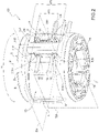
- a rotary head 1 for string trimmer according to the present invention is globally denoted with 1.
- the rotary head 1 comprises a rotary body 2 made in a single piece.
- the rotary body 2 has a longitudinal rotation axis X.
- the rotary body 2 has a base 3, a side wall 4 and an upper wall 5.
- the rotary body 2 has one or more return areas ⁇ , each of which is configured to accommodate a respective portion of line F (depicted in figures 4 to 6 ) and cause a plurality of consecutive curves C of said line F.
- the rotary head 1 has a plurality of paths P at each return area ⁇ .
- the paths are two in number: PI and PII.
- Each path P is configured to keep the portion of line F locked.
- path PI is configured to accommodate lines having a medium to maximum section, i.e. about 3 to 5 mm.
- path PII is configured to accommodate lines having a medium to small section, i.e. from 1.5 to 3 mm.
- Each path P has a pair of channels, identified here below as upper channel 7 and lower channel 8, crosswise to the rotation axis X and to a groove 9 substantially parallel to the rotation axis X and which connects the upper channel 7 and the lower channel 8 to each other at respective ends.
- the upper channel 7 and the lower channel 8 are parallel to each other and have ends aligned along an axis substantially parallel to the rotation axis X.
- the upper channels 7 and the lower channels 8 are marked with the suffix I or II for path PI and PII respectively.
- the rotary head 1 has an outer path PI and an inner path PII.
- the inner path PII is substantially made inside the outer path PI.
- the outer path PI and the inner path PII share one same groove 9.
- the upper channel 711 and the lower channel 811 of the inner path PII are interposed along the groove 9 between the upper channel 7I and the lower channel 8I of the outer path PI.
- the rotary head 1 has a return portion 12 configured to obtain a plurality of curves C on the line F.
- the rotary head 1 has a plurality of curvature portions R at the return portion 12.
- the rotary body 2 can have a different arrangement from the paths P, for example, it could have two or more paths set longitudinally side by side between one another, i.e. it could have an upper path and a lower path, wherein the upper channel and the lower channel of the upper path are arranged, in use, above, with respect to the rotation axis X of the upper channel and the lower channel of the lower path.
- the rotary head 1 has a recess 11 obtained on the side wall 4 of the rotary body 2.
- the recess 11 communicates radially with the outside of the rotary body 2.
- the return portion 12 is arranged inside the recess 11 and delimits, with the recess 11, the upper channels 7, the lower channels 8 and the groove 9.
- the return portion 12 has been obtained in the rotary body 2.
- the recess 11 is radially delimited by a bottom surface 13 and has a depth, which varies from an area of attack ⁇ (visible in figures 2 to 6 ) to at least the return area ⁇ . At the return area ⁇ , the recess 11 has a depth, which is substantially equal to, or greater than the radial extension of the return portion 12. According to the embodiment illustrated in figure 1 , the recess 11 is through, i.e. the bottom surface 13 is substantially flat at the return area ⁇ , to subsequently connect to the outer diameter of the rotary head 1 in point ⁇ .
- the rotary body 2 comprises boards 14, which are substantially crosswise to the rotation axis X and which extend inside the recess 11 towards the return portion 12 so as to laterally delimit the upper channels 7 and the lower channels 8.
- the boards 14 radially delimit the upper channels 7 and the lower channels 8.
- the return portion 12 is interposed along the circumference of the rotary head 1 between the boards 14 and the area of attack ⁇ .
- Each board 14 is radially delimited by a radial striking surface 151.
- the radial striking surface 151 is substantially parallel to the bottom surface 13.
- Each board 14 is laterally delimited by a side striking surface 1511.
- the radial striking surface 151 protrudes outwards from the bottom surface 13.
- the radial striking surface 151 is curved, i.e. it is substantially parallel to the bottom surface 13 at a central zone and it is degrading, i.e. it reduces the distance with the bottom surface 13, both towards the base 3 and towards the upper wall 5.
- each side striking surface 1511 is inclined, so as to form an angle ⁇ , which is equal to, or smaller than 90°, with the radial striking surface 151.
- the return portion 12 has a side surface 10, which is facing, in use, the side striking surface 1511 of each board 14.
- the groove 9 is delimited by the side surface 10 by the radial striking surface 151 and by the side striking surface 1511.
- the side surface 10 forms an angle ⁇ with the radial striking surface 151.
- the angle ⁇ is equal to, or smaller than 90°.
- the side surface 10 is substantially parallel to the side striking surface 1511.
- the lateral distance between each side striking surface 1511 and the side surface 10 of the return portion 12 is greater than the maximum thickness of the mountable line portion F.
- the depth, i.e. the radial extension, of the groove 9 is configured to accommodate up to the maximum section of the line it can accommodate, so that, in use, the line doesn't protrude beyond the diameter of the rotary head 1.
- the line F is retained inside paths PI, PII by means of successive curves C obtained on different planes, in particular, which are transversal to one another, as will be shown better below.
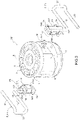
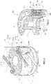
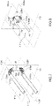
- a variant of the rotary head according to the present invention is denoted with 101 in figures 2 and 3 .
- the rotary head 101 substantially comprises all of the components of the rotary head 1 described above. Below, and in figures 2 to 6 , the components in common keep the same numbering and are not repeated for brevity.
- the rotary head 101 comprises a return unit 112 instead of the return portion 12 described above, which is made in a separate piece from the body of the rotary head 101.
- the return unit 112 is connected to the rotary body 2 by releasable means, for example, by a pin 16.
- the return unit 112 has recesses 17, which laterally delimit, together with the bottom surface 13, the upper channels 7 and the lower channels 8.
- the boards 14 are partly obtained in the rotary body 2 and partly in the return unit 112.
- one central board 14 protrudes from the rotary body 2 and two lateral boards 14 protrude from the return unit 112.
- the rotary head 1 or 101 is made of a polymer material.
- the rotary head 1 or 101 can be made of a metal material.
- the rotary head 1 or 101 can have a different number of paths PI or PII.
- the rotary head 1 or 101 can have a single path P.
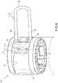
- the portion of line F inserted in the rotary head 1 or 101 is bent, in use, about the return portion 12 or the return unit 112 and has an upper portion 18 and a lower portion 19, which protrude from the rotary head and which are connected to each other by a connection portion 20.
- the upper channel 7, the lower channel 8 and the groove 9 are configured so as to create a succession of curves C on different planes, which will be shown better below.
- the upper portion 18 is inserted inside the upper channel 7,7I
- the lower portion 19 is inserted inside the lower channel 8, 8I
- the connection portion 20 is inserted inside the respective groove 9.
- planes ⁇ 1A and ⁇ 1B are parallel to one another.
- Planes ⁇ 1A and ⁇ 1B are perpendicular to the longitudinal axis X.
- Plane ⁇ 2 is radial and coplanar to the longitudinal axis X.
- Planes ⁇ 1A and ⁇ 1B are substantially perpendicular to plane ⁇ 2.
- the line F forms a curve C1A on plane ⁇ 1A and a curve C2A on plane ⁇ 2.
- the line forms a curve C1B on plane ⁇ 1B and a curve C2B on plane ⁇ 2.
- the curvature radii of the curves C1A, C2A, C1B and C2B described above are configured to prevent the line F from sliding during use of the rotary head 1.
- the consecutiveness between the curves C1A and C2A and the consecutiveness between the curves C1B and C2B prevents the portions 18 and 19 from unthreading.
- a further curve C11A of the line is comprised on plane ⁇ 1A, which is created in use exiting the return portion 12 or the return unit 112.
- the upper portion 18 and the lower portion 19 can oscillate on plane ⁇ 1A from a position, in which they are substantially flattened against the bottom surface 13, to a position, in which they are partially bent on the return portion 12 or the return unit 112.
- the curves C11A and C11B which are formed, have radii, which are such as to prevent the breaking of the line portion F.
- the curvature radii of the curves C1A, C2A, C1B and C2B, described above, are different, depending on the type of path PI or PII used.
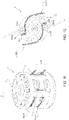
- the curves C1A, C2A, C1B and C2B, which the portion of line F makes along path PI and PII inside the rotary head 1 or 101 respectively, are schematised in figures 7 and 8 . In figures 7 and 8 , I and II are used to indicate the curves obtained with path PI and path PII respectively.
- the return portion 12 has a plurality of curvature portions R, each of which has a respective different curvature radius.
- the curvature portions R are portions of the side surface 10.
- Each curvature portion R acts as a local shoulder element for the portion of line F.
- Each curvature portion R is substantially a portion of an osculating circle, which determines a corresponding curvature C of the line F.
- Each curvature portion R develops on a respective plane, has a respective curvature centre and is determined by a respective radius.
- the curvature portions R can develop on different planes to one another.
- the curvature portions R can overlap, at least partially at one same portion of the line F, or they can be in succession with one another, i.e. one after the other, in contact with one another, or spaced apart.
- curvature portions R along path PI are illustrated in detail in figures 9, 10 and 5 .
- curvature portions R along path PII are illustrated in detail in figures 11, 12 and 5 .
- the return portion 12 has a curvature portion R1I for creating the curve C1AI.
- the curvature portion R1I develops on a plane (in this particular case, on the plane ⁇ 1AI), which is substantially perpendicular to the longitudinal axis X of the rotary head 1.
- the curvature portion R1I has a radius from 3 to 4 mm, preferably 3.5 mm.
- the same curvature portion R1I serves to create the curve C1B at a different position along the longitudinal axis X (in this particular case, at the plane ⁇ 1BI in figure 7 ) .
- the return portion 12 has a curvature portion R11I (for creating the curve C11A when the line F is bent, in use, at least partially about the return portion 12.
- the curvature portion R11I has a radius from 6 to 7 mm, preferably 6.5 mm.
- the same curvature portion R11I serves to create the curve C11B at a different position along the longitudinal axis X (in this particular case, at the plane ⁇ 1BI in figure 7 ) .
- the return portion 12 has a curvature portion R2I (schematised in figure 7 ) for creating the curve C2AI.
- the curvature portion R2I develops on a plane (in this particular case, on the plane ⁇ 2), which is substantially coplanar and radial to the longitudinal axis X of the rotary head 1.
- the curvature portion R2I has a radius from 4 to 6 mm, preferably 5 mm.
- the return portion 12 has a curvature portion R1II for creating the curve C1AII.
- the curvature portion R1II develops on a plane (in this particular case, on the plane ⁇ 1AII), which is substantially perpendicular to the longitudinal axis X of the rotary head 1.
- the curvature portion R1II has a radius from 1 to 3 mm, preferably 2 mm.
- the same curvature portion R1II serves to create the curve C1BII at a different position along the longitudinal axis X (in this particular case, at the plane ⁇ 1BII in figure 7 ) .
- the return portion 12 has a curvature portion R11II (for creating the curve C11AII when the line F is bent, in use, at least partially about the return portion 12.
- the curvature portion R11II has a radius from 6 to 7 mm, preferably 6.5 mm.
- the same curvature portion R11II serves to create the curve C11BII at a different position along the longitudinal axis X (in this particular case, at the plane ⁇ 1BI in figure 7 ) .
- the curvature portions R11I and R11II can substantially be equal to each other, as described and illustrated herein, or they can be different from each other.
- the return portion 12 has a curvature portion R2II (schematised in figure 7 ) for creating the curve C2AII.
- the curvature portion R2II develops on a plane (in this particular case, on the plane ⁇ 2), which is substantially coplanar and radial to the longitudinal axis X of the rotary head 1.
- the curvature portion R2II has a radius from 1 to 3 mm, preferably 2 mm.
- curvature portions described above are also to be understood as present in the rotary head 101 with the return element 112 and they are not repeated and shown again for brevity's sake. Thus, in the figures relating to the rotary head 101, the same references are reported to denote the same curvature portions R.
- the curvature portion R11I (for path PI) or the curvature portion R11II has a radius K resulting from the following equation.
- K De 2 + s + df + 1 2
- the presence of the curves C11A, C11B with a curvature radius K greater than 6 mm prevents the line F from deforming, i.e. becoming worn.
- edges or bumps are absent at the area, in which the line F is subject to stress, causing oscillations thereof (shown by the dotted line in 10 and 13), which, on coming into contact with the line F, could cause the breakage thereof.
- the sharp edges close to the oscillation area of the line F are completely eliminated.
- the ends of the line portion F are pulled, so as to trap the connection portion 20 inside the respective groove 9.
- the portion of line F is kept fixed inside the groove 9 by the respective wall 15 with an angle of less than 90°with respect to the wall 13.
- the portion of line F can be pulled until it has only one single portion 18 or 19, which protrudes from the rotary head 1 or 101.
- the presence of the recess 11 allows the line F to stay protected and partially supported in use.
- an operator must overcome the forces opposing the curves C1A and C1B, given that, at the time of removing the line F, the curves C2 don't oppose such operation, i.e. they don't apply any resistance. Therefore, the operator is able to remove a line F for the replacement thereof, with little effort and no tools.
- the sequence of curvature portions R described above allows the line F to be kept fastened to the rotary head 1 or 101.
Landscapes
- Life Sciences & Earth Sciences (AREA)
- Environmental Sciences (AREA)
- Harvester Elements (AREA)
- Brushes (AREA)
- Polishing Bodies And Polishing Tools (AREA)
Claims (10)
- Drehkopf für Fadentrimmer mit mindestens einem Fadenabschnitt (F); wobei der Drehkopf (1; 101) einen Drehkörper (2) aufweist, welcher eine Rotationsachse (X) und eine Seitenwand (4) aufweist; wobei der Drehkörper als ein einziges Stück hergestellt ist; wobei der Drehkörper (2) einen oder mehrere Rückführbereiche oder -mittel (12; 112) aufweist, von denen jeder oder jedes so konfiguriert ist, dass er einen jeweiligen Fadenabschnitt (F) mittels aufeinanderfolgender Kurven (C1A, C1B, C2, C11) auf verschiedenen Ebenen (π1A, π1B, π2) arretiert; wobei jeder Rückführbereich oder jedes Rückführmittel (12; 112) entlang der Seitenwand (4) des Drehkörpers (2) angeordnet ist; wobei ein in einen Rückführbereich oder ein Rückführmittel (12; 112) eingeführter Fadenabschnitt (F) im Gebrauch nicht radial nach außen aus dem Drehkörper (2) herausragt; wobei mindestens zwei aufeinanderfolgende Kurven (C1A, C2; C1B, C2) auf zwei jeweiligen Ebenen (π1A, π2; π1B, π2) senkrecht zueinander erhalten werden.
- Drehkopf gemäß einem der vorhergehenden Ansprüche, wobei jeder Drehkopf (1; 101) einen oder mehrere Pfade (PI, PII) aufweist; wobei jeder Pfad (PI; PII) so konfiguriert ist, dass er einen jeweiligen Fadenabschnitt (F) biegt; wobei jeder Pfad (PI; PII) ein Paar von Kanälen (7, 8), die im Wesentlichen quer zu der Rotationsachse (X) verlaufen, und eine Nut (9) aufweist, die im Wesentlichen parallel zu der Rotationsachse (X) verläuft; wobei die Kanäle (7, 8) durch die Nut (9) miteinander verbunden sind.
- Drehkopf nach Anspruch 2 mit einer ersten äußeren Bahn (PI) und einer zweiten inneren Bahn (PII), wobei die zweite innere Bahn (PII) in die erste äußere Bahn (PI) eingesetzt ist.
- Drehkopf nach Anspruch 3, wobei die erste äußere Bahn (PI) und die zweite innere Bahn (PII) dieselbe Nut (9) teilen; wobei der obere Kanal (7II) und der untere Kanal (8II) der inneren Bahn (PII) entlang der Nut (9) zwischen dem oberen Kanal (7I) und dem unteren Kanal (8I) der äußeren Bahn (PI) angeordnet sind.
- Drehkopf nach Anspruch 3 oder 4, der entlang des ersten Pfades (PI) einen ersten Krümmungsabschnitt (R1I) zur Erzeugung einer ersten Kurve (C1A; C1B) aufweist; wobei der erste Krümmungsabschnitt (R1I) einen Radius im Bereich von 3 bis 4 mm, vorzugsweise 3. 5 mm aufweist; wobei der Drehkopf (1; 101) einen zweiten Krümmungsabschnitt (R2I) zur Erzeugung einer zweiten Kurve (C2A; C2B) aufweist; wobei der zweite Krümmungsabschnitt (R2I) einen Radius im Bereich von 4 bis 6 mm, vorzugsweise 5 mm, aufweist.
- Drehkopf nach einem der Ansprüche 3 bis 5, der entlang des zweiten Pfades (PII) einen ersten Krümmungsabschnitt (R1II) zur Erzeugung einer ersten Kurve (C1A; C1B) aufweist; wobei der erste Krümmungsabschnitt (R1II) einen Radius im Bereich von 1 bis 3 m, vorzugsweise 2 mm, aufweist; wobei der Drehkopf (1; 101) einen zweiten Krümmungsabschnitt (R2II) zum Erzeugen einer zweiten Kurve (C2A; C2B) aufweist; wobei der zweite Krümmungsabschnitt (R2II) einen Radius im Bereich von 1 bis 3 mm, vorzugsweise 2 mm, aufweist.
- Drehkopf nach einem der Ansprüche 3 bis 6 und mit einem dritten Krümmungsabschnitt (R11I; R11I) zur Erzeugung einer dritten Kurve (C11AI; C11BI; C11AII; C11BII); wobei der dritte Krümmungsabschnitt einen Radius (K) aufweist, der sich aus der folgenden Gleichung ergibt:
 De dem äußeren Durchmesser des Drehkopfes entspricht;s der Größe entspricht, die zum Sicherstellen einer Befestigung des Drehkopfes gebraucht wird ist, die üblicherweise mittels eines zur Längsachse X koaxialen Befestigungssechskant erreicht wird;is the size needed to ensure the fixing of the rotary head, usually obtained by means of a fixing hexagon coaxial to the longitudinal axis X;df dem Durchmesser des Fadens F entspricht.
 - Drehkopf nach einem der vorhergehenden Ansprüche, wobei der Drehkörper (2) für jeden Rückführbereich oder jedes Rückführmittel (12; 112) eine in der Seitenwand (4) des Drehkörpers (2) ausgebildete Ausnehmung (11) aufweist; wobei jede Ausnehmung (11) radial mit der Außenseite des Rotationskörpers (2) in Verbindung steht; wobei jeder Rückführbereich oder jedes Rückführmittel (12; 112) innerhalb einer jeweiligen Ausnehmung (11) angeordnet ist; wobei jeder Rückführbereich oder jedes Rückführmittel (12; 112) mit der Ausnehmung (11) die jeweiligen Kanäle (7, 8) und die Nut (9) begrenzt; wobei jeder Rückführbereich oder jede Rückführeinrichtung (12; 112) als ein einziges Stück zusammen mit dem Drehkörper (2) hergestellt ist oder mit dem Drehkörper (2) mittels eines lösbaren Mittels, zum Beispiel mittels eines Stifts, verbunden ist.
- Drehkopf nach Anspruch 8, wobei die Ausnehmung (11) radial durch eine Bodenfläche (13) begrenzt ist; die Ausnehmung (11) eine Tiefe aufweist, die von einem Angriffsbereich (α) zu einem Rückführbereich (β) variabel ist; die Bodenfläche (13) im Angriffsbereich (α) im Wesentlichen komplanar zur Seitenwand (4) ist; die Aussparung (11) eine Tiefe hat, die im Wesentlichen gleich oder größer ist als die radiale Ausdehnung des Rückführmittels (12; 112) im Rückführbereich (β); das Rückführmittel (12; 112) innerhalb der Aussparung (11) angeordnet ist und zwischen dem Angriffsbereich (α) und dem Rückführbereich (β) liegt.
- Drehkopf nach Anspruch 8 oder 9, der eine oder mehrere Platten (14) umfasst, von denen jede quer zur Rotationsachse (X) in eine entsprechende Aussparung (11) in Richtung eines entsprechenden Rückführmittels (12; 112) ragt, wobei jede Platte (14) seitlich einen entsprechenden Endabschnitt eines entsprechenden Kanals (7; 8) begrenzt; wobei die Nut (9) zwischen dem Rückführmittel (12; 112) und jeder Platte (14) angeordnet ist; wobei jede Platte (14) radial durch eine seitliche Anschlagfläche (15II) begrenzt ist, die dem Rückführmittel (12; 112) zugewandt und so geneigt ist, dass sie in Bezug auf die Bodenfläche (13) einen Winkel (γ) bildet, der gleich oder kleiner als 90° ist.
Applications Claiming Priority (1)
| Application Number | Priority Date | Filing Date | Title |
|---|---|---|---|
| IT102019000010002A IT201900010002A1 (it) | 2019-06-25 | 2019-06-25 | Testa rotante per decespugliatore |
Publications (2)
| Publication Number | Publication Date |
|---|---|
| EP3756439A1 EP3756439A1 (de) | 2020-12-30 |
| EP3756439B1 true EP3756439B1 (de) | 2022-04-06 |
Family
ID=68343234
Family Applications (1)
| Application Number | Title | Priority Date | Filing Date |
|---|---|---|---|
| EP20182390.3A Active EP3756439B1 (de) | 2019-06-25 | 2020-06-25 | Drehkopf für fadenschneider |
Country Status (4)
| Country | Link |
|---|---|
| US (1) | US11570947B2 (de) |
| EP (1) | EP3756439B1 (de) |
| ES (1) | ES2914867T3 (de) |
| IT (1) | IT201900010002A1 (de) |
Families Citing this family (1)
| Publication number | Priority date | Publication date | Assignee | Title |
|---|---|---|---|---|
| IT201900010002A1 (it) * | 2019-06-25 | 2020-12-25 | Flash Cutter S R L Con Unico Socio | Testa rotante per decespugliatore |
Citations (1)
| Publication number | Priority date | Publication date | Assignee | Title |
|---|---|---|---|---|
| EP0903071B1 (de) * | 1997-09-17 | 2002-12-04 | Techtronic Industries Co., Ltd. | Schneidkopf und Fadenmäher |
Family Cites Families (12)
| Publication number | Priority date | Publication date | Assignee | Title |
|---|---|---|---|---|
| WO1998018312A1 (en) * | 1996-10-29 | 1998-05-07 | Conceptual Marketing & Development, Inc. | Attachment head for vegetation cutting devices |
| US6487780B1 (en) * | 1999-05-07 | 2002-12-03 | Peterson Science & Technology, Inc. | Rotary device for automatically deploying and retracting a cord-like element from a storage device |
| US20020073556A1 (en) * | 2000-12-15 | 2002-06-20 | Robert L. Phillips | Top loading fixed line trimmer head |
| US6519857B1 (en) * | 2001-11-21 | 2003-02-18 | Proulx Manufacturing, Inc. | Fixed line head for flexible line rotary trimmers |
| US6986239B1 (en) * | 2004-06-25 | 2006-01-17 | Andrew Compton | Lawn mower cutting implement |
| US20060005520A1 (en) * | 2004-07-09 | 2006-01-12 | Joe Weidman | Trimming apparatus and mower deck comprising same |
| ITFI20120159A1 (it) * | 2012-08-02 | 2014-02-03 | Arnetoli Motor Srl | "testina taglia-erba" |
| EP2979531B1 (de) * | 2014-08-01 | 2017-01-25 | Speed France S.A.S. | Schneidkopf für eine Vegetationsschneidemaschine |
| IT201800007966A1 (it) * | 2018-08-08 | 2020-02-08 | Tecomec Srl | Testina per decespugliatore |
| IT201900010002A1 (it) * | 2019-06-25 | 2020-12-25 | Flash Cutter S R L Con Unico Socio | Testa rotante per decespugliatore |
| US11968924B2 (en) * | 2020-04-20 | 2024-04-30 | Ardisam, Inc. | Heads for string trimmers and mowers |
| US20220039315A1 (en) * | 2020-08-07 | 2022-02-10 | Etudes Constructions Metalliques Et Mecaniques | Head of a string trimmer, and string trimmer comprising such a head |
-
2019
- 2019-06-25 IT IT102019000010002A patent/IT201900010002A1/it unknown
-
2020
- 2020-06-23 US US16/909,219 patent/US11570947B2/en active Active
- 2020-06-25 EP EP20182390.3A patent/EP3756439B1/de active Active
- 2020-06-25 ES ES20182390T patent/ES2914867T3/es active Active
Patent Citations (1)
| Publication number | Priority date | Publication date | Assignee | Title |
|---|---|---|---|---|
| EP0903071B1 (de) * | 1997-09-17 | 2002-12-04 | Techtronic Industries Co., Ltd. | Schneidkopf und Fadenmäher |
Also Published As
| Publication number | Publication date |
|---|---|
| ES2914867T3 (es) | 2022-06-17 |
| EP3756439A1 (de) | 2020-12-30 |
| IT201900010002A1 (it) | 2020-12-25 |
| US20200404839A1 (en) | 2020-12-31 |
| US11570947B2 (en) | 2023-02-07 |
Similar Documents
| Publication | Publication Date | Title |
|---|---|---|
| DE3537971C2 (de) | Sägevorrichtung zur Herstellung von Nuten | |
| EP3718717B1 (de) | Schneidkopfanordnung für eine zentrifugalschneidvorrichtung und zentrifugalvorrichtung mit der anordnung | |
| US12186928B2 (en) | Tubing cutter | |
| DE68905106T2 (de) | Schneidelemente fuer drehbohrmeissel. | |
| US3999620A (en) | Core barrel | |
| EP3756439B1 (de) | Drehkopf für fadenschneider | |
| EP3011820B1 (de) | Kopf für einen kantentrimmer | |
| US9702251B2 (en) | Cutting tool assembly including retainer sleeve with retention member | |
| KR980000725A (ko) | 기어커팅 및 다듬질작업용 라운드 바 블레이드 및 이것이 결합된 커터헤드 | |
| EP0585106B1 (de) | Geschraubter Sicherungsring für Rollenmeissel und Verfahren zur Herstellung eines solchen Meissels | |
| US20160298408A1 (en) | Lower Mill Spaced Cutting Ring Structure | |
| US1873245A (en) | Method of making a connection | |
| KR101215786B1 (ko) | 공기 분배 조립체를 구비한 로터리 커터 | |
| US7000713B2 (en) | Blockless reamer | |
| US5706583A (en) | Twin utility hacksaw blade | |
| DE202009012569U1 (de) | Einlippen-Tieflochbohrer | |
| JP7463454B2 (ja) | 調整可能なパンチ本体組立体 | |
| DE3341871A1 (de) | Axialverdichter | |
| JP3822168B2 (ja) | 精密内側溝を切削するためのブローチ | |
| US6158320A (en) | Saw arbor with splined mandrel and mating, timed internally and externally splined saw blade mounting sleeve | |
| US262588A (en) | Twist-drill | |
| DE4127581A1 (de) | Rotorklinge fuer maehwerke | |
| DE202010015045U1 (de) | Einlippenbohrer | |
| US4890945A (en) | Rotary die cylinder bearer attachment | |
| DE10261114A1 (de) | Kreuzgelenk mit einem Sicherungselement |
Legal Events
| Date | Code | Title | Description |
|---|---|---|---|
| PUAI | Public reference made under article 153(3) epc to a published international application that has entered the european phase |
Free format text: ORIGINAL CODE: 0009012 |
|
| STAA | Information on the status of an ep patent application or granted ep patent |
Free format text: STATUS: THE APPLICATION HAS BEEN PUBLISHED |
|
| AK | Designated contracting states |
Kind code of ref document: A1 Designated state(s): AL AT BE BG CH CY CZ DE DK EE ES FI FR GB GR HR HU IE IS IT LI LT LU LV MC MK MT NL NO PL PT RO RS SE SI SK SM TR |
|
| AX | Request for extension of the european patent |
Extension state: BA ME |
|
| STAA | Information on the status of an ep patent application or granted ep patent |
Free format text: STATUS: REQUEST FOR EXAMINATION WAS MADE |
|
| 17P | Request for examination filed |
Effective date: 20210629 |
|
| RBV | Designated contracting states (corrected) |
Designated state(s): AL AT BE BG CH CY CZ DE DK EE ES FI FR GB GR HR HU IE IS IT LI LT LU LV MC MK MT NL NO PL PT RO RS SE SI SK SM TR |
|
| GRAP | Despatch of communication of intention to grant a patent |
Free format text: ORIGINAL CODE: EPIDOSNIGR1 |
|
| STAA | Information on the status of an ep patent application or granted ep patent |
Free format text: STATUS: GRANT OF PATENT IS INTENDED |
|
| INTG | Intention to grant announced |
Effective date: 20211029 |
|
| GRAS | Grant fee paid |
Free format text: ORIGINAL CODE: EPIDOSNIGR3 |
|
| GRAA | (expected) grant |
Free format text: ORIGINAL CODE: 0009210 |
|
| STAA | Information on the status of an ep patent application or granted ep patent |
Free format text: STATUS: THE PATENT HAS BEEN GRANTED |
|
| AK | Designated contracting states |
Kind code of ref document: B1 Designated state(s): AL AT BE BG CH CY CZ DE DK EE ES FI FR GB GR HR HU IE IS IT LI LT LU LV MC MK MT NL NO PL PT RO RS SE SI SK SM TR |
|
| REG | Reference to a national code |
Ref country code: GB Ref legal event code: FG4D |
|
| REG | Reference to a national code |
Ref country code: CH Ref legal event code: EP |
|
| REG | Reference to a national code |
Ref country code: AT Ref legal event code: REF Ref document number: 1480420 Country of ref document: AT Kind code of ref document: T Effective date: 20220415 |
|
| REG | Reference to a national code |
Ref country code: IE Ref legal event code: FG4D |
|
| REG | Reference to a national code |
Ref country code: DE Ref legal event code: R096 Ref document number: 602020002534 Country of ref document: DE |
|
| REG | Reference to a national code |
Ref country code: ES Ref legal event code: FG2A Ref document number: 2914867 Country of ref document: ES Kind code of ref document: T3 Effective date: 20220617 |
|
| REG | Reference to a national code |
Ref country code: LT Ref legal event code: MG9D |
|
| REG | Reference to a national code |
Ref country code: NL Ref legal event code: MP Effective date: 20220406 |
|
| REG | Reference to a national code |
Ref country code: GR Ref legal event code: EP Ref document number: 20220401126 Country of ref document: GR Effective date: 20220707 |
|
| REG | Reference to a national code |
Ref country code: AT Ref legal event code: MK05 Ref document number: 1480420 Country of ref document: AT Kind code of ref document: T Effective date: 20220406 |
|
| PG25 | Lapsed in a contracting state [announced via postgrant information from national office to epo] |
Ref country code: NL Free format text: LAPSE BECAUSE OF FAILURE TO SUBMIT A TRANSLATION OF THE DESCRIPTION OR TO PAY THE FEE WITHIN THE PRESCRIBED TIME-LIMIT Effective date: 20220406 |
|
| PG25 | Lapsed in a contracting state [announced via postgrant information from national office to epo] |
Ref country code: SE Free format text: LAPSE BECAUSE OF FAILURE TO SUBMIT A TRANSLATION OF THE DESCRIPTION OR TO PAY THE FEE WITHIN THE PRESCRIBED TIME-LIMIT Effective date: 20220406 Ref country code: PT Free format text: LAPSE BECAUSE OF FAILURE TO SUBMIT A TRANSLATION OF THE DESCRIPTION OR TO PAY THE FEE WITHIN THE PRESCRIBED TIME-LIMIT Effective date: 20220808 Ref country code: NO Free format text: LAPSE BECAUSE OF FAILURE TO SUBMIT A TRANSLATION OF THE DESCRIPTION OR TO PAY THE FEE WITHIN THE PRESCRIBED TIME-LIMIT Effective date: 20220706 Ref country code: LT Free format text: LAPSE BECAUSE OF FAILURE TO SUBMIT A TRANSLATION OF THE DESCRIPTION OR TO PAY THE FEE WITHIN THE PRESCRIBED TIME-LIMIT Effective date: 20220406 Ref country code: HR Free format text: LAPSE BECAUSE OF FAILURE TO SUBMIT A TRANSLATION OF THE DESCRIPTION OR TO PAY THE FEE WITHIN THE PRESCRIBED TIME-LIMIT Effective date: 20220406 Ref country code: FI Free format text: LAPSE BECAUSE OF FAILURE TO SUBMIT A TRANSLATION OF THE DESCRIPTION OR TO PAY THE FEE WITHIN THE PRESCRIBED TIME-LIMIT Effective date: 20220406 Ref country code: BG Free format text: LAPSE BECAUSE OF FAILURE TO SUBMIT A TRANSLATION OF THE DESCRIPTION OR TO PAY THE FEE WITHIN THE PRESCRIBED TIME-LIMIT Effective date: 20220706 Ref country code: AT Free format text: LAPSE BECAUSE OF FAILURE TO SUBMIT A TRANSLATION OF THE DESCRIPTION OR TO PAY THE FEE WITHIN THE PRESCRIBED TIME-LIMIT Effective date: 20220406 |
|
| PG25 | Lapsed in a contracting state [announced via postgrant information from national office to epo] |
Ref country code: RS Free format text: LAPSE BECAUSE OF FAILURE TO SUBMIT A TRANSLATION OF THE DESCRIPTION OR TO PAY THE FEE WITHIN THE PRESCRIBED TIME-LIMIT Effective date: 20220406 Ref country code: PL Free format text: LAPSE BECAUSE OF FAILURE TO SUBMIT A TRANSLATION OF THE DESCRIPTION OR TO PAY THE FEE WITHIN THE PRESCRIBED TIME-LIMIT Effective date: 20220406 Ref country code: LV Free format text: LAPSE BECAUSE OF FAILURE TO SUBMIT A TRANSLATION OF THE DESCRIPTION OR TO PAY THE FEE WITHIN THE PRESCRIBED TIME-LIMIT Effective date: 20220406 Ref country code: IS Free format text: LAPSE BECAUSE OF FAILURE TO SUBMIT A TRANSLATION OF THE DESCRIPTION OR TO PAY THE FEE WITHIN THE PRESCRIBED TIME-LIMIT Effective date: 20220806 |
|
| REG | Reference to a national code |
Ref country code: DE Ref legal event code: R097 Ref document number: 602020002534 Country of ref document: DE |
|
| PG25 | Lapsed in a contracting state [announced via postgrant information from national office to epo] |
Ref country code: SM Free format text: LAPSE BECAUSE OF FAILURE TO SUBMIT A TRANSLATION OF THE DESCRIPTION OR TO PAY THE FEE WITHIN THE PRESCRIBED TIME-LIMIT Effective date: 20220406 Ref country code: SK Free format text: LAPSE BECAUSE OF FAILURE TO SUBMIT A TRANSLATION OF THE DESCRIPTION OR TO PAY THE FEE WITHIN THE PRESCRIBED TIME-LIMIT Effective date: 20220406 Ref country code: RO Free format text: LAPSE BECAUSE OF FAILURE TO SUBMIT A TRANSLATION OF THE DESCRIPTION OR TO PAY THE FEE WITHIN THE PRESCRIBED TIME-LIMIT Effective date: 20220406 Ref country code: MC Free format text: LAPSE BECAUSE OF FAILURE TO SUBMIT A TRANSLATION OF THE DESCRIPTION OR TO PAY THE FEE WITHIN THE PRESCRIBED TIME-LIMIT Effective date: 20220406 Ref country code: EE Free format text: LAPSE BECAUSE OF FAILURE TO SUBMIT A TRANSLATION OF THE DESCRIPTION OR TO PAY THE FEE WITHIN THE PRESCRIBED TIME-LIMIT Effective date: 20220406 Ref country code: DK Free format text: LAPSE BECAUSE OF FAILURE TO SUBMIT A TRANSLATION OF THE DESCRIPTION OR TO PAY THE FEE WITHIN THE PRESCRIBED TIME-LIMIT Effective date: 20220406 Ref country code: CZ Free format text: LAPSE BECAUSE OF FAILURE TO SUBMIT A TRANSLATION OF THE DESCRIPTION OR TO PAY THE FEE WITHIN THE PRESCRIBED TIME-LIMIT Effective date: 20220406 |
|
| PLBE | No opposition filed within time limit |
Free format text: ORIGINAL CODE: 0009261 |
|
| STAA | Information on the status of an ep patent application or granted ep patent |
Free format text: STATUS: NO OPPOSITION FILED WITHIN TIME LIMIT |
|
| REG | Reference to a national code |
Ref country code: BE Ref legal event code: MM Effective date: 20220630 |
|
| 26N | No opposition filed |
Effective date: 20230110 |
|
| PG25 | Lapsed in a contracting state [announced via postgrant information from national office to epo] |
Ref country code: AL Free format text: LAPSE BECAUSE OF FAILURE TO SUBMIT A TRANSLATION OF THE DESCRIPTION OR TO PAY THE FEE WITHIN THE PRESCRIBED TIME-LIMIT Effective date: 20220406 |
|
| PG25 | Lapsed in a contracting state [announced via postgrant information from national office to epo] |
Ref country code: LU Free format text: LAPSE BECAUSE OF NON-PAYMENT OF DUE FEES Effective date: 20220625 Ref country code: IE Free format text: LAPSE BECAUSE OF NON-PAYMENT OF DUE FEES Effective date: 20220625 |
|
| PG25 | Lapsed in a contracting state [announced via postgrant information from national office to epo] |
Ref country code: SI Free format text: LAPSE BECAUSE OF FAILURE TO SUBMIT A TRANSLATION OF THE DESCRIPTION OR TO PAY THE FEE WITHIN THE PRESCRIBED TIME-LIMIT Effective date: 20220406 Ref country code: BE Free format text: LAPSE BECAUSE OF NON-PAYMENT OF DUE FEES Effective date: 20220630 |
|
| P01 | Opt-out of the competence of the unified patent court (upc) registered |
Effective date: 20230414 |
|
| REG | Reference to a national code |
Ref country code: CH Ref legal event code: PL |
|
| PG25 | Lapsed in a contracting state [announced via postgrant information from national office to epo] |
Ref country code: MK Free format text: LAPSE BECAUSE OF FAILURE TO SUBMIT A TRANSLATION OF THE DESCRIPTION OR TO PAY THE FEE WITHIN THE PRESCRIBED TIME-LIMIT Effective date: 20220406 Ref country code: CY Free format text: LAPSE BECAUSE OF FAILURE TO SUBMIT A TRANSLATION OF THE DESCRIPTION OR TO PAY THE FEE WITHIN THE PRESCRIBED TIME-LIMIT Effective date: 20220406 Ref country code: CH Free format text: LAPSE BECAUSE OF NON-PAYMENT OF DUE FEES Effective date: 20230630 |
|
| PG25 | Lapsed in a contracting state [announced via postgrant information from national office to epo] |
Ref country code: HU Free format text: LAPSE BECAUSE OF FAILURE TO SUBMIT A TRANSLATION OF THE DESCRIPTION OR TO PAY THE FEE WITHIN THE PRESCRIBED TIME-LIMIT; INVALID AB INITIO Effective date: 20200625 |
|
| PG25 | Lapsed in a contracting state [announced via postgrant information from national office to epo] |
Ref country code: MT Free format text: LAPSE BECAUSE OF FAILURE TO SUBMIT A TRANSLATION OF THE DESCRIPTION OR TO PAY THE FEE WITHIN THE PRESCRIBED TIME-LIMIT Effective date: 20220406 |
|
| PG25 | Lapsed in a contracting state [announced via postgrant information from national office to epo] |
Ref country code: BG Free format text: LAPSE BECAUSE OF FAILURE TO SUBMIT A TRANSLATION OF THE DESCRIPTION OR TO PAY THE FEE WITHIN THE PRESCRIBED TIME-LIMIT Effective date: 20220406 |
|
| PG25 | Lapsed in a contracting state [announced via postgrant information from national office to epo] |
Ref country code: BG Free format text: LAPSE BECAUSE OF FAILURE TO SUBMIT A TRANSLATION OF THE DESCRIPTION OR TO PAY THE FEE WITHIN THE PRESCRIBED TIME-LIMIT Effective date: 20220406 |
|
| GBPC | Gb: european patent ceased through non-payment of renewal fee |
Effective date: 20240625 |
|
| PG25 | Lapsed in a contracting state [announced via postgrant information from national office to epo] |
Ref country code: GB Free format text: LAPSE BECAUSE OF NON-PAYMENT OF DUE FEES Effective date: 20240625 |
|
| PGFP | Annual fee paid to national office [announced via postgrant information from national office to epo] |
Ref country code: DE Payment date: 20250626 Year of fee payment: 6 |
|
| PGFP | Annual fee paid to national office [announced via postgrant information from national office to epo] |
Ref country code: IT Payment date: 20250407 Year of fee payment: 6 |
|
| PGFP | Annual fee paid to national office [announced via postgrant information from national office to epo] |
Ref country code: FR Payment date: 20250624 Year of fee payment: 6 |
|
| PGFP | Annual fee paid to national office [announced via postgrant information from national office to epo] |
Ref country code: GR Payment date: 20250619 Year of fee payment: 6 |
|
| PGFP | Annual fee paid to national office [announced via postgrant information from national office to epo] |
Ref country code: ES Payment date: 20250710 Year of fee payment: 6 |
|
| PG25 | Lapsed in a contracting state [announced via postgrant information from national office to epo] |
Ref country code: TR Free format text: LAPSE BECAUSE OF FAILURE TO SUBMIT A TRANSLATION OF THE DESCRIPTION OR TO PAY THE FEE WITHIN THE PRESCRIBED TIME-LIMIT Effective date: 20220406 |