EP3755919B1 - Festsattelkörper für eine scheibenbremsscheibe - Google Patents
Festsattelkörper für eine scheibenbremsscheibe Download PDFInfo
- Publication number
- EP3755919B1 EP3755919B1 EP19712033.0A EP19712033A EP3755919B1 EP 3755919 B1 EP3755919 B1 EP 3755919B1 EP 19712033 A EP19712033 A EP 19712033A EP 3755919 B1 EP3755919 B1 EP 3755919B1
- Authority
- EP
- European Patent Office
- Prior art keywords
- bridge
- resting
- guiding
- bridge element
- radial
- Prior art date
- Legal status (The legal status is an assumption and is not a legal conclusion. Google has not performed a legal analysis and makes no representation as to the accuracy of the status listed.)
- Active
Links
Images








Classifications
-
- F—MECHANICAL ENGINEERING; LIGHTING; HEATING; WEAPONS; BLASTING
- F16—ENGINEERING ELEMENTS AND UNITS; GENERAL MEASURES FOR PRODUCING AND MAINTAINING EFFECTIVE FUNCTIONING OF MACHINES OR INSTALLATIONS; THERMAL INSULATION IN GENERAL
- F16D—COUPLINGS FOR TRANSMITTING ROTATION; CLUTCHES; BRAKES
- F16D55/00—Brakes with substantially-radial braking surfaces pressed together in axial direction, e.g. disc brakes
- F16D55/02—Brakes with substantially-radial braking surfaces pressed together in axial direction, e.g. disc brakes with axially-movable discs or pads pressed against axially-located rotating members
- F16D55/22—Brakes with substantially-radial braking surfaces pressed together in axial direction, e.g. disc brakes with axially-movable discs or pads pressed against axially-located rotating members by clamping an axially-located rotating disc between movable braking members, e.g. movable brake discs or brake pads
- F16D55/228—Brakes with substantially-radial braking surfaces pressed together in axial direction, e.g. disc brakes with axially-movable discs or pads pressed against axially-located rotating members by clamping an axially-located rotating disc between movable braking members, e.g. movable brake discs or brake pads with a separate actuating member for each side
-
- F—MECHANICAL ENGINEERING; LIGHTING; HEATING; WEAPONS; BLASTING
- F16—ENGINEERING ELEMENTS AND UNITS; GENERAL MEASURES FOR PRODUCING AND MAINTAINING EFFECTIVE FUNCTIONING OF MACHINES OR INSTALLATIONS; THERMAL INSULATION IN GENERAL
- F16D—COUPLINGS FOR TRANSMITTING ROTATION; CLUTCHES; BRAKES
- F16D65/00—Parts or details
- F16D65/005—Components of axially engaging brakes not otherwise provided for
- F16D65/0068—Brake calipers
- F16D65/0075—Brake calipers assembled from a plurality of parts
-
- F—MECHANICAL ENGINEERING; LIGHTING; HEATING; WEAPONS; BLASTING
- F16—ENGINEERING ELEMENTS AND UNITS; GENERAL MEASURES FOR PRODUCING AND MAINTAINING EFFECTIVE FUNCTIONING OF MACHINES OR INSTALLATIONS; THERMAL INSULATION IN GENERAL
- F16D—COUPLINGS FOR TRANSMITTING ROTATION; CLUTCHES; BRAKES
- F16D65/00—Parts or details
- F16D65/14—Actuating mechanisms for brakes; Means for initiating operation at a predetermined position
- F16D65/16—Actuating mechanisms for brakes; Means for initiating operation at a predetermined position arranged in or on the brake
- F16D65/18—Actuating mechanisms for brakes; Means for initiating operation at a predetermined position arranged in or on the brake adapted for drawing members together, e.g. for disc brakes
-
- F—MECHANICAL ENGINEERING; LIGHTING; HEATING; WEAPONS; BLASTING
- F16—ENGINEERING ELEMENTS AND UNITS; GENERAL MEASURES FOR PRODUCING AND MAINTAINING EFFECTIVE FUNCTIONING OF MACHINES OR INSTALLATIONS; THERMAL INSULATION IN GENERAL
- F16D—COUPLINGS FOR TRANSMITTING ROTATION; CLUTCHES; BRAKES
- F16D65/00—Parts or details
- F16D65/14—Actuating mechanisms for brakes; Means for initiating operation at a predetermined position
- F16D65/16—Actuating mechanisms for brakes; Means for initiating operation at a predetermined position arranged in or on the brake
- F16D65/18—Actuating mechanisms for brakes; Means for initiating operation at a predetermined position arranged in or on the brake adapted for drawing members together, e.g. for disc brakes
- F16D65/183—Actuating mechanisms for brakes; Means for initiating operation at a predetermined position arranged in or on the brake adapted for drawing members together, e.g. for disc brakes with force-transmitting members arranged side by side acting on a spot type force-applying member
-
- F—MECHANICAL ENGINEERING; LIGHTING; HEATING; WEAPONS; BLASTING
- F16—ENGINEERING ELEMENTS AND UNITS; GENERAL MEASURES FOR PRODUCING AND MAINTAINING EFFECTIVE FUNCTIONING OF MACHINES OR INSTALLATIONS; THERMAL INSULATION IN GENERAL
- F16D—COUPLINGS FOR TRANSMITTING ROTATION; CLUTCHES; BRAKES
- F16D55/00—Brakes with substantially-radial braking surfaces pressed together in axial direction, e.g. disc brakes
- F16D2055/0004—Parts or details of disc brakes
- F16D2055/0016—Brake calipers
- F16D2055/002—Brake calipers assembled from a plurality of parts
-
- F—MECHANICAL ENGINEERING; LIGHTING; HEATING; WEAPONS; BLASTING
- F16—ENGINEERING ELEMENTS AND UNITS; GENERAL MEASURES FOR PRODUCING AND MAINTAINING EFFECTIVE FUNCTIONING OF MACHINES OR INSTALLATIONS; THERMAL INSULATION IN GENERAL
- F16D—COUPLINGS FOR TRANSMITTING ROTATION; CLUTCHES; BRAKES
- F16D65/00—Parts or details
- F16D65/78—Features relating to cooling
- F16D2065/785—Heat insulation or reflection
-
- F—MECHANICAL ENGINEERING; LIGHTING; HEATING; WEAPONS; BLASTING
- F16—ENGINEERING ELEMENTS AND UNITS; GENERAL MEASURES FOR PRODUCING AND MAINTAINING EFFECTIVE FUNCTIONING OF MACHINES OR INSTALLATIONS; THERMAL INSULATION IN GENERAL
- F16D—COUPLINGS FOR TRANSMITTING ROTATION; CLUTCHES; BRAKES
- F16D2200/00—Materials; Production methods therefor
- F16D2200/0004—Materials; Production methods therefor metallic
- F16D2200/0026—Non-ferro
- F16D2200/003—Light metals, e.g. aluminium
-
- F—MECHANICAL ENGINEERING; LIGHTING; HEATING; WEAPONS; BLASTING
- F16—ENGINEERING ELEMENTS AND UNITS; GENERAL MEASURES FOR PRODUCING AND MAINTAINING EFFECTIVE FUNCTIONING OF MACHINES OR INSTALLATIONS; THERMAL INSULATION IN GENERAL
- F16D—COUPLINGS FOR TRANSMITTING ROTATION; CLUTCHES; BRAKES
- F16D2200/00—Materials; Production methods therefor
- F16D2200/0034—Materials; Production methods therefor non-metallic
- F16D2200/0039—Ceramics
- F16D2200/0047—Ceramic composite, e.g. C/C composite infiltrated with Si or B, or ceramic matrix infiltrated with metal
-
- F—MECHANICAL ENGINEERING; LIGHTING; HEATING; WEAPONS; BLASTING
- F16—ENGINEERING ELEMENTS AND UNITS; GENERAL MEASURES FOR PRODUCING AND MAINTAINING EFFECTIVE FUNCTIONING OF MACHINES OR INSTALLATIONS; THERMAL INSULATION IN GENERAL
- F16D—COUPLINGS FOR TRANSMITTING ROTATION; CLUTCHES; BRAKES
- F16D2200/00—Materials; Production methods therefor
- F16D2200/006—Materials; Production methods therefor containing fibres or particles
Definitions
- the present invention relates to a disc brake caliper body, preferably of fixed caliper type, which can be used on vehicles and in particular, but not necessarily, intended for high-performance motor cars.
- the present invention further relates to a disc brake caliper and to a disc brake assembly having a caliper body of the type specified above.
- the brake caliper is generally arranged straddling the outer peripheral margin of a brake disc, adapted to rotate about a rotation axis (A-A) defining an axial direction (X-X).
- a radial direction (R-R) arranged substantially orthogonal to said axial direction (X-X), and a punctually tangential or altogether circumferential direction (C-C), orthogonal to both said axial direction (X-X) and said radial direction (R-R), is further defined.
- a caliper body of fixed caliper disc brake can be associated with a disc so as to maintain its distance from the disc unchanged.
- Said known caliper body comprises a first half-body, adapted to accommodate first means for generating a braking action, arranged facing a first braking surface of an outer side of said disc, as well as a second half-body, adapted to accommodate second means for generating the braking action, arranged facing a second braking surface of an inner side of said disc.
- Said first and second half-bodies are connected, by means of fixing means, to two bridge elements arranged straddling the disc.
- outer side means the side of the disc brake assembly which faces towards the outside of the vehicle when it is fitted on the hub and stub axle, or hub-holder, of the wheel.
- inner side means the side of the assembly which faces towards the inside of the vehicle when it is fitted on the wheel hub.
- the discs for disc brakes comprise a bell, adapted to associate the disc with a vehicle hub, from which an annular portion, named braking band, intended to cooperate with pads of a caliper, extends.
- Said braking band is intended to cooperate with calipers for disc brake adapted to apply a braking action on the vehicle, whereby applying, by means of pads, friction on opposite surfaces of the two plates, named braking surfaces.
- the generated heat determines the onset of many undesired phenomena, such as, for example, the deformation of the braking band, the formation of cracks on the braking surfaces or localized state transformations of the material constituting the braking band which, in turn, lead to the deterioration of the braking band itself.
- the significant and high forces which bias the caliper body are a clamping action and a braking action.
- These actions are produced by the means adapted to generate the braking action, e.g. at least one pair of cylinder and piston assemblies, accommodated in the half-bodies, the pistons of which act by means of the pads on the opposite braking surfaces of the disc.
- the clamping action of the pads against the braking surfaces of the disc is directed axially and is balanced by the structure of the caliper body which is arranged straddling the disc.
- the bridge elements which, by embracing the disc, form closed force loops. This action biases the caliper body, determining a spreading of the bridge elements, or, in other words, a bending of the caliper body along the axes in tangential direction, or with concavity about radial axes.
- the braking action is instead directed tangentially and in particular in the rotation direction of the disc. This action is transmitted by the disc to the pads and contrasted by shoulders provided in the bridge elements, so as to be released onto the supporting means of the caliper body which are rigidly coupled, for example, to a stub axle or hub-carrier of a wheel of the vehicle. This action biases the bridge elements whereby also deforming portions thereof necessary to connect the half-bodies. Furthermore, the braking action is released onto the supporting means only on the side of the caliper body facing the inner side of the disc, whereby also determining a bending of the caliper body about the radial axes.
- the aforesaid actions are notoriously not uniformly distributed on the caliper body and are of a magnitude which is variable over time, whereby causing, in addition to deformations of the caliper body which are sometimes unacceptable for a correct operation of the disc brake, also vibrations and undesired screeching.
- a caliper body of fixed caliper disc brake which has such structural and functional characteristics as to overcome the aforesaid disadvantages described with reference to the prior art and in particular to lighten the caliper body but at the same time strengthen the bridge elements arranged straddling the disc brake and at the same time simplify the construction of the caliper body and especially the working of the thrust device housings, e.g. of the cylinders adapted to accommodate the thrust pistons adapted to bias the brake pads.
- a disc brake of the floating caliper type in which a caliper having a single piston or multiple pistons but all on the same side of the disc brake is supported in the condition that the brake caliper can be freely moved with respect to a supporting element, or bracket, which is fixed to a fixed part of a vehicle, e.g. to the hub-holder, to support the pair of brake pads and with a sliding constraint which allows the supporting element to float or move freely with respect to the disc.
- the piston is arranged only on one side of the rotor, i.e. the piston is arranged only on the inner side, or vehicle side, of the disc.
- opposed piston disc brakes have become common, because they can produce an excellent braking force, by virtue of their greater efficiency.
- pistons are provided on both sides of a disc brake. During braking operations, a pair of pads is pushed against both opposite braking surfaces of the disc brake rotor by both opposite pistons.
- the rotor of the brake disc is interposed between the cylinders adapted to accommodate the pistons and the open sides of the cylinders are opposite to one another.
- Document GB2214581 by Freni Brembo S.p.A shows a single-block brake caliper body solution with opposed pistons or fixed caliper body.
- this single-block caliper body has a structure in which the elongated portions facing the disc brake have a plurality of cylinders integrated in a single body.
- the structure described in the aforesaid patent publication is disadvantageous in that it requires time and complex special methods for working the cylinders and assembling the disc brake of the opposed piston type made in a single block. Therefore, it is impossible to avoid an increase in production costs.
- the body having a plurality of cylinders is divided into half-bodies having an attachment portion, or attachment half-body, to be connected to a stationary portion of a vehicle, e.g. a hub-holder, and also having a cylinder on the inner front side, and a portion or outer body having a cylinder on the outer front side.
- a vehicle e.g. a hub-holder
- the half-bodies are connected and fixed to one another by bolts.
- caliper bodies are known from GB936222 by DUNLOP RUBBER CO ; US3261429 by Bendix Corp. ; US5538105 by DAYTON WALTHER CORP and US5819886 by Robert Null.
- the bolts for attaching and fixing the inner body and the outer body to one another receive a braking torque which is given by the outer brake pad and biased by the pistons of the outer body, braking action generated by the friction caused between the outer side face of the rotor, or disc brake, and the outer pad in the braking process. It is therefore necessary for the bolts to withstand this braking torque. Therefore, the diameters of the bolts must be large in size, to the extent of increasing size and weight of the caliper body.
- the weight of the disc brake which is supported in an end portion of the angle portion of a vehicle, or corner, becomes an unsprung weight, i.e. not suspended by elastic and/or damping elements. Accordingly, even when the weight of the disc brake increases only slightly, the running performance of a vehicle is also strongly biased by the increase of unsprung weight.
- connection elements or bridges
- the need remains strongly felt to improve the accuracy with which the connection elements, or bridges, are connected to the half-bodies, in order to stiffen the parallelogram created by the half-bodies and the bridges.
- the further need is felt to provide a supporting surface of the bridge connection elements either parallel or perpendicular to the releasing plane of the braking action.
- the problem underlying the present invention is thus to provide a fixed caliper body and a caliper, which have structural and functional characteristics such as to satisfy the aforementioned requirements and at the same time solve the drawbacks mentioned with reference to the prior art.
- the suggested solution allows considerably simplifying the working operations of the half-bodies of the caliper.
- the suggested solution allows obtaining a braking comfort much higher than the solutions of the prior art, and consequently a reduction of the vibrations and in particular an absence of the vibrations which cause screeching.
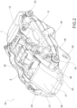
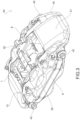
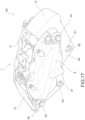
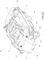
- a fixed brake caliper 1 for a disc brake disc 2 is provided.
- Said disc 2 comprises opposite braking surfaces 3, 4 and an axial-symmetric disc body 5 adapted to rotate about a rotation axis A-A defining an axial direction X-X, said disc body 5 develops radially along a radial direction R-R orthogonal to said axial direction X-X, as well as along a circumferential direction C-C orthogonal both to said axial direction X-X and to said radial direction R-R.
- Said fixed caliper body 1 comprises a first half-body 6.
- Said first half-body 6 is adapted to face either directly or indirectly a first braking surface 3 of said braking surfaces 3, 4 of said disc 2.
- Said first half-body comprises at least one first housing 7 for a first biasing device 8 to generate a first braking action by applying a pressure on a brake pad 35 and make it abut against a first braking surface 3 of a brake disc 2.
- Said fixed caliper body 1 comprises a second half-body 9 comprising at least one second housing 10 for a second thrust device 11 to generate a second braking action.
- Said second half-body 9 is adapted to face either directly or indirectly a second braking surface 4 of said braking surfaces 3, 4 of said disc 2.
- Said fixed caliper body 1 comprises at least one second bridge element 12 to connect and support said second half-body 9 to said first half-body 6.
- Said at least one bridge element 12 comprises at least one first guiding and resting bridge surface 13 oriented according to a first predetermined resting plane 14 and at least one second guiding and resting bridge surface 15 oriented according to a second predetermined resting plane 16.
- Said first half-body 6 comprises at least one first protrusion 17 which protrudes in a cantilevered manner in axial direction X-X towards the opposite second half-body 9 or towards said brake disc 2 when the caliper is fitted on a vehicle.
- Said second half-body 9 comprises at least one second protrusion 18 which protrudes in a cantilevered manner in axial direction X-X towards the opposite first half-body 6.
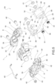
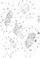
- Said first half-body 6, said second half-body 9 and said at least one bridge element 12 are three mutually separable components.
- said at least one first protrusion 17 delimits a first guiding and resting semi-body surface 19 oriented, when said bridge element 12 is connected to said first half-body 6 and when the caliper is in working conditions, according to said first predetermined resting plane 14 parallel to said at least one first bridge surface 13.
- Said at least one second protrusion 18 delimits a second guiding and resting half-body surface 20 oriented according to said second predetermined resting plane 16 and parallel to said at least one second bridge surface 15 when said bridge element 12 is connected to said second half-body 9.
- said at least one bridge element 12 firmly rests said at least one first bridge surface 13 thereof against said first half-body surface 19 by connecting and orienting said at least one bridge element 12 to said first half-body 6, creating a rest for said at least one bridge element 12 in circumferential direction C-C.
- said at least one bridge element 12 firmly rests said at least one second bridge surface 15 thereof against said second half-body surface 20 by connecting and orienting said at least one bridge element 12 to said second half-body 9 in circumferential direction C-C.
- said fixed caliper body 1 comprises at least one first bridge element 21 to connect and support said second half-body 9 to said first half-body 6.
- Said at least one bridge element 21 comprises at least one third guiding and resting bridge surface 22 oriented according to a third predetermined resting plane 23 and at least one fourth guiding and resting bridge surface 24 oriented according to a fourth predetermined resting plane 25.
- Said first half-body 6 comprises at least one third protrusion 26 which protrudes in a cantilevered manner in axial direction X-X towards the opposite second half-body 9.
- Said second half-body 9 comprises at least one fourth protrusion 27 which protrudes in a cantilevered manner in axial direction X-X towards the opposite first half-body 6.
- Said at least one third protrusion 26 delimits a third guiding and resting half-body surface 28 oriented according to said third predetermined resting plane 23 and parallel to said at least one third bridge surface 22 when said bridge element 21 is connected to said first half-body 6.
- Said at least one fourth protrusion 27 delimits a fourth guiding and resting half-body surface 29 oriented according to said fourth predetermined resting plane 25 and parallel to said at least one fourth bridge surface 24 when said bridge element 21 is connected to said second half-body 9.
- Said at least one second bridge element 21 firmly rests said at least one third bridge surface 22 thereof against said third half-body surface 28 by connecting and orienting said at least one bridge element 21 to said first half-body 6, creating a rest for said at least one bridge element 21 in circumferential direction C-C.
- Said at least one bridge element 21 firmly rests said at least one fourth bridge surface 24 thereof against said fourth half-body surface 29 by connecting and orienting said at least one bridge element 21 to said second half-body 9, in circumferential direction C-C.
- said at least one first and/or second bridge element 12, 21 each comprise a first and a second guiding and radial resting bridge surface 30, 31 which, when said bridge element 12, 21 is connected to said first and second half-bodies 6, 9, are oriented according to radial R-R and circumferential C-C directions.
- Said first and second half-body 6, 9 comprise two first and two second guiding and radial resting half-body surfaces 32, 33.
- Said at least one first and/or second bridge element 12, 21 firmly rests its first and second guiding and radial resting bridge surfaces 30, 31 against said first and second guiding and radial resting half-body surfaces 32, 33 by connecting and orienting said at least one first and/or second bridge element 12, 21 to said first and second half-bodies 6, 9, creating a rest for said at least one bridge element 21 in axial direction X-X.
- At least one of said protrusions 17, 18, 26, 27 comprises at least one pad supporting surface 34 adapted to be arranged transversely to said opposite braking surfaces 3, 4 to receive the resting of at least one brake pad 35 in circumferential direction C-C.
- said first and second half-bodies 6, 9 are made of a first material and said at least one bridge element 12, 21 is made of at least one second material, different from said first material.
- said first material is aluminum.
- said second material is a fiber-reinforced composite material.
- the matrix may be ceramic and/or polymeric fiber-reinforced with carbon and/or glass and/or basalt and/or alumina and/or silicon carbide and/or silicon fibers.
- the matrix may be reinforced with inserts made with high-rigidity ceramic preforms, inserted in the matrix e.g. of molten aluminum, e.g. by co-fusing.
- said first material has a higher density than said second material.
- said second material has a modulus of elasticity greater than the modulus of elasticity of the first material.
- said first and/or second guiding and resting semi-body surfaces 19, 20 and said first and/or second guiding and radial resting semi-body surfaces 32, 33 are flat surfaces.
- said first guiding and resting semi-body surfaces 19, 20 and said first guiding and radial resting semi-body surfaces 32, 33 are mutually orthogonal surfaces.
- said second guiding and resting semi-body surfaces 19, 20 and said second guiding and radial resting semi-body surfaces 32, 33 are mutually orthogonal surfaces.
- each half-body 6, 9 said first and/or second guiding and resting semi-body surface 19, 20 and said first and/or second guiding and radial resting semi-body surface 32, 33 are adjacent in pairs to form an edge.
- said first and/or second guiding and resting half-body surface 19, 20 and said first and/or second radial guiding and resting half-body surface 32, 33 are surfaces adjacent in pairs to form a centering system of the bridge element 12, 21 against the half-bodies 6, 9, whereby forming a parallelogram structure having particularly rigid characteristics and at the same time very small dimensions in radial direction R-R.
- said first and/or second guiding and resting bridge surfaces 13, 15 and said first and/or second guiding and radial resting bridge surfaces 30, 31 are flat surfaces.
- said first guiding and resting bridge surfaces 13, 15 and said first guiding and radial resting bridge surfaces 30, 31 are mutually orthogonal surfaces.
- each bridge element 12, 21, said second guiding and resting bridge surface 13, 15 and said second guiding and radial resting bridge surface 30, 31 are mutually orthogonal surfaces.
- each bridge element 12, 21, said first and/or second guiding and resting bridge surface 13, 15 and said first and/or second guiding and radial resting bridge surface 30, 31 are adjacent in pairs to form an edge.
- said first and/or second guiding and resting bridge surface 13, 15 and said first and/or second radial guiding and resting bridge surface 30, 31 can be flat surfaces, but also of other shapes, such as for example cylindrical or tapered to facilitate the centering of the bridge elements 12, 21 on said first and second half-body 6, 9.
- said first and/or second guiding and resting bridge surfaces 13, 15 and said first and/or second radial guiding and resting bridge surfaces 30, 31 are surfaces adjacent in pairs to form a centering system of the bridge element 12, 21 against the half-bodies 6, 9, whereby forming a parallelogram structure having particularly rigid characteristics and at the same time very small dimensions in radial direction R-R.
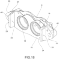
- said at least one bridge element 12, 21 forms an inverted "U"-shaped bridge housing 39 adapted to be arranged straddling said brake disc 2.
- said bridge housing 39 is shielded in its portion facing the brake disc 2 by a heat-guard sheet 44 fixed to said at least one bridge element 12, 21, e.g. by means of fixing screws.
- a solution of heat-guard sheet is known from WO 2017/021874 A1 by the applicant.
- said at least one bridge element 12, 21 comprises a first and a second bridge side wall 36, 37 which at least partially faces said first and second half-body 6, 9 and an arc-shaped connection portion of the bridge 38.
- said first and one second bridge side walls 36, 37 form a first and a second opposite guiding and radial resting bridge surface 30, 31.
- said first and second half-bodies 6, 9 comprise a half-body through hole 40.
- said first and second bridge elements 12, 21 comprise a threaded bridge housing 41.
- said fixed caliper body 1 comprises at least one stud 42 accommodated in said half-body through hole 40 and screwed into said threaded bridge housing 41 firmly connecting said at least one bridge element 12, 21 to said half-body 6, 9.
- each of said first and second guiding and radial resting semi-body surfaces 32, 33 of said first and second half-bodies 6, 9 comprise a through hole of the half-body 40.
- each of said first and second guiding and radial resting bridge surfaces 30, 31 of said first and second bridge elements 12, 21 comprise a threaded bridge housing 41.
- At least two studs 42 are accommodated in said half-body through holes 40 and screwed into said facing threaded bridge housings 41 firmly connecting said first and second bridge elements 12, 21 to said first and second half-bodies 6, 9.
- said threaded bridge housing 41 comprises a threaded bridge bush 43 keyed into housings provided in the body of said first and/or second bridge elements 12, 21.
- said threaded bridge housing 41 comprises a threaded bridge bush 43 embedded in the body of said first and/or second bridge elements 12, 21.
- said threaded bridge housing 41 comprises a threaded bridge bush 43 co-molded with the body of said first and/or second bridge elements 12, 21.
- said half-body through hole 40 and said threaded bridge housing 41 are directed along said axial direction X-X and are adapted to face said braking surfaces 3, 4 of said brake disc 2.
- said first and second half-bodies 6, 9 are fluidically supplied to feed brake fluid to said at least first and second housing 7, 10 to apply a thrust action with said at least first and second thrust element 8, 11 on brake pads 35 adapted to abut on said braking surfaces 3, 4 of said brake disc 2 to apply a braking action.
- said first half-body 6 is arranged facing a vehicle and fluidically connected to the braking system; said first and second half-bodies 6, 9 are mutually fluidically connected by means of brake fluid feeding pipe 45 which externally embraces said at least one bridge element 12 and/or 21.
- said first half-body 6 is arranged facing a vehicle and fluidically connected to the braking system; said first and second half-bodies 6, 9 are mutually fluidically connected by means of brake fluid feeding pipe 46 embedded, e.g. co-molded or co-fused, with said at least one bridge element 12 and/or 21.
- said first half-body 6 is arranged facing a vehicle and fluidically connected to the braking system; said first and second half-bodies 6, 9 are mutually fluidically connected by means of a working brake fluid feeding pipe 48 obtained by perforating at least one bridge element 12 and/or 21.
- said first and second bridge elements 12, 21 are mutually connected by a bridge crossbar 49.
- said first and second bridge elements 12, 21 are mutually connected by a bridge crossbar 49 and said first and second bridge elements 12, 21 and said bridge crossbar 49 are in one piece.
- said bridge crossbar 49 faces a vehicle and is adapted to connect the fixed caliper body 1 to a hub-holder.
- said bridge crossbar 49 comprises bridge crossbar connection housings 50 to a hub-holder, adapted to receive connecting screws of the fixed caliper body 1 to said hub-holder.
- said bridge crossbar connection housings 50 comprise hub-holder connection bushes 51, adapted to receive connecting screws of the fixed caliper body 1 to said hub-holder.
- said hub-holder connection bushes 51 are keyed into bridge crossbar connection housings 50.
- said hub-holder connection bushes 51 are embedded in said bridge crossbar 49.
- said hub-holder connection bushes 51 are co-molded or co-fused in said bridge crossbar 49.
- said first and second bridge elements 12, 21 are mutually separate components and each connected to said first and second half-bodies 6, 9.
- said first half-body 6 faces a vehicle and comprises body connection extensions 52 forming body connection housings 53 adapted to receive screws for connecting the fixed caliper body 1 to a hub-holder.
- said first and/or second half-bodies 6, 9 each comprise two first and/or second housings 7, 10 for accommodating at least two first and/or second thrust devices 8, 11 so as to apply multiple thrust actions to associated brake pads 35 on each opposite braking surfaces 3, 4 of the disc brake 2.
- the present invention further relates to a brake caliper 54 comprising a caliper body as defined in any one of the embodiments above and comprising at least two opposite thrust devices 8, 11 and at least two opposite brake pads 35.
Landscapes
- Engineering & Computer Science (AREA)
- General Engineering & Computer Science (AREA)
- Mechanical Engineering (AREA)
- Braking Arrangements (AREA)
Claims (15)
- Festsattelkörper (1) für eine Scheibenbremsscheibe (2),- wobei die Scheibe (2) entgegengesetzte Bremsflächen (3, 4) und einen achssymmetrischen Scheibenkörper (5) aufweist, der dazu ausgelegt ist, sich um eine Drehachse (A-A) herum zu drehen, welche eine axiale Richtung (X-X) definiert, wobei sich der Scheibenkörper (5) radial entlang einer radialen Richtung (R-R) orthogonal zur axialen Richtung (X-X) sowie entlang einer Umfangsrichtung (C-C) orthogonal zu sowohl der axialen Richtung (X-X) als auch zu der radialen Richtung (R-R) abwickelt; wobei der Festsattelkörper (1) aufweist:wobei- einen ersten Halbkörper (6), der zumindest ein erstes Gehäuse (7) für eine erste Druckvorrichtung (8) zum Erzeugen einer ersten Bremsaktion aufweist; wobei der erste Halbkörper (6) dazu ausgelegt ist, entweder direkt oder indirekt zu einer ersten Bremsfläche (3) der Bremsflächen (3, 4) der Scheibe (2) zu weisen;- einen zweiten Halbkörper (9), der zumindest ein zweites Gehäuse (10) für eine zweite Druckvorrichtung (11) aufweist, um eine zweite Bremsaktion zu erzeugen; wobei der zweite Halbkörper (9) dazu ausgelegt ist, entweder direkt oder indirekt zu einer zweiten Bremsfläche (4) der Bremsflächen (3, 4) der Scheibe (2) zu weisen;- zumindest ein erstes Brückenelement (12) zum Verbinden und Tragen des zweiten Halbkörpers (9) an dem ersten Halbkörper (6); wobei das zumindest eine erste Brückenelement (12) eine erste Führungs- und Stützbrückenfläche (13) aufweist, die gemäß einer ersten vorbestimmten Stützebene (14) orientiert ist, und zumindest eine zweite Führungs- und Stützbrückenfläche (15), die gemäß einer zweiten vorbestimmten Stützebene (16) orientiert ist;- der erste Halbkörper (6) zumindest einen ersten Vorsprung (17) aufweist, der auslegerartig in axialer Richtung (X-X) zu dem gegenüberliegenden zweiten Halbkörper (9) vorsteht;- der zweite Halbkörper (9) zumindest einen zweiten Vorsprung (18) aufweist, der auslegerartig in axialer Richtung (X-X) zu dem gegenüberliegenden ersten Halbkörper (6) vorsteht;- wobei der erste Halbkörper (6), der zweite Halbkörper (9) und das zumindest eine erste Brückenelement (12) drei voneinander trennbare Komponenten sind;- der zumindest eine erste Vorsprung (17) eine erste Führungs- und Stützhalbkörperfläche (19) begrenzt, die gemäß der ersten vorbestimmten Stützebene (14) und parallel zu der zumindest einen ersten Führungs- und Stützbrückenfläche (13) orientiert ist, wenn das erste Brückenelement (12) mit dem ersten Halbkörper (6) verbunden ist;- der zumindest eine zweite Vorsprung (18) eine zweite Führungs- und Stützhalbkörperfläche (20) begrenzt, die gemäß der zweiten vorbestimmten Stützebene (16) und parallel zu der zumindest einen zweiten Führungs- und Stützbrückenfläche (15) orientiert ist, wenn das erste Brückenelement (12) mit dem zweiten Halbkörper (9) verbunden ist;- wobei sich das zumindest eine erste Brückenelement (12) mit seiner zumindest einen ersten Führungsbrückenfläche (13) fest gegen die erste Halbkörperfläche (19) abstützt, durch Verbinden und Orientieren des zumindest einen ersten Brückenelements (12) mit dem ersten Halbkörper (16), was eine Stütze für das zumindest eine erste Brückenelement (12) in Umfangsrichtung (C-C) erzeugt;- wobei sich das zumindest eine erste Brückenelement (12) mit seiner zumindest einen zweiten Führungs- und Stützbrückenfläche (15) fest gegen die zweite Halbkörperfläche (20) abstützt, durch Verbinden und Orientieren des zumindest einen ersten Brückenelements (12) mit dem zweiten Halbkörper (9) in Umfangsrichtung (C-C);dadurch gekennzeichnet, dass- zumindest einer der Vorsprünge (17, 18) zumindest eine Klotzträgerfläche (34) aufweist, die dazu ausgelegt ist, quer zu den entgegengesetzten Bremsflächen (3, 4) angeordnet zu werden, um die Stütze von zumindest einem Bremsklotz (15) in Umfangsrichtung (C-C) aufzunehmen.
- Der Festsattelkörper (1) nach Anspruch 1, wobei:- der Festsattelkörper (1) zumindest ein zweites Brückenelement (21) aufweist, um den zweiten Halbkörper (9) mit dem ersten Halbkörper (6) zu verbinden und zu tragen; wobei das zumindest eine zweite Brückenelement zumindest eine dritte Führungs- und Stützbrückenfläche (22) aufweist, die gemäß einer dritten vorbestimmten Stützebene (23) orientiert ist, und zumindest eine vierte Führungs- und Stützbrückenfläche (24), die gemäß einer vierten vorbestimmten Stützebene (24) orientiert ist;- der erste Halbkörper (6) zumindest einen dritten Vorsprung (26) aufweist, der auslegerartig in axialer Richtung (X-X) zu dem gegenüberliegenden zweiten Halbkörper (9) vorsteht;- der zweite Halbkörper (9) zumindest einen vierten Vorsprung (27) aufweist, der auslegerartig in axialer Richtung (X-X) zu dem gegenüberliegenden ersten Halbkörper (6) vorsteht;- der zumindest eine dritte Vorsprung (26) eine dritte Führungs- und Stützhalbkörperfläche (28) begrenzt, die gemäß der dritten vorbestimmten Stützebene (23) und parallel zu zumindest der dritten Führungs- und Stützbrückenfläche (22) orientiert ist, wenn das zweite Brückenelement (21) mit dem ersten Halbkörper (6) verbunden ist;- der zumindest eine vierte Vorsprung (27) eine vierte Führungs- und Stützhalbkörperfläche (29) begrenzt, die gemäß der vierten vorbestimmten Stützebene (22) und parallel zu der zumindest einen vierten Führungs- und Stützbrückenfläche (24) orientiert ist, wenn das zumindest eine zweite Brückenelement (21) mit dem zweiten Halbkörper (9) verbunden ist;- wobei sich das zumindest eine zweite Brückenelement (21) mit seiner zumindest einen dritten Führungs- und Stützbrückenfläche (29) fest gegen die dritte Führungs- und Stützhalbkörperfläche (28) abstützt, durch Verbinden und Orientieren zumindest des zweiten Brückenelements (21) mit dem ersten Halbkörper (6), was eine Stütze für das zumindest eine zweite Brückenelement (21) in Umfangsrichtung (C-C) erzeugt;- wobei sich das zumindest eine zweite Brückenelement (21) mit seiner zumindest einen vierten Führungs- und Stützbrückenfläche (26) fest gegen die vierte Führungs- und Stützhalbkörperfläche (29) abstützt, durch Verbinden und Orientieren des zumindest einen zweiten Brückenelements (21) mit dem zweiten Halbkörper (9) in Umfangsrichtung (C-C).
- Der Festsattelkörper (1) nach Anspruch 2, wobei:- das zumindest eine erste und/oder zweite Brückenelement (12, 21) jeweils eine erste und eine zweite Führungs- und Radialstütz-Brückenfläche (30, 31) aufweist, die, wenn das zumindest eine erste und/oder zweite Brückenelement (12, 21) mit den ersten und zweiten Halbkörpern (6, 9) verbunden ist, gemäß radialen (R-R) und Umfangs- (C-C) Richtungen orientiert sind;- der erste und zweite Halbkörper (6, 9) zwei erste und zwei zweite Führungs- und Radialstütz-Halbkörperflächen (32, 33) aufweist;- wobei sich das zumindest eine erste und/oder zweite Brückenelement (12, 21) mit seinen ersten und zweiten Führungs- und Radialstütz-Brückenflächen (30, 31) fest gegen die ersten und zweiten Führungs- und Radialstütz-Halbkörperflächen (32, 33) abstützt, durch Verbinden und Orientieren des zumindest einen ersten und/oder zweiten Brückenelements (12, 21) mit den ersten und zweiten Halbkörpern (6, 9), was eine Stütze für das zumindest eine erste und/oder zweite Brückenelement (12, 21) in axialer Richtung (X-X) erzeugt.
- Der Festsattelkörper (1) nach einem der vorhergehenden Ansprüche, wobei:- die ersten und zweiten Halbkörper (6, 9) aus einem ersten Material hergestellt sind und das zumindest eine erste Brückenelement (12) aus zumindest einem zweiten Material hergestellt ist, was sich von dem ersten Material unterscheidet.
- Der Festsattelkörper (1) nach Anspruch 4, wobei:- das erste Material Aluminium ist; und/oder wobei- das zweite Material ein faserverstärktes Kompositmaterial ist, zum Beispiel Materialien mit einer Keramik- und/oder Polymermatrix, faserverstärkt mit Carbon und/oder Glas und/oder Basalt und/oder Aluminiumoxid und/oder Siliciumcarbid und/oder Siliciumfasern; und/oder wobei- das erste Material eine größere Dichte hat als das zweite Material; und/oder wobei- das zweite Material einen Elastizitätsmodul hat, der größer ist als der Elastizitätsmodul des ersten Materials.
- Der Festsattelkörper (1) nach Anspruch 3, wobei:- in jedem Halbkörper (6, 9) die erste und/oder zweite Führungs- und Stützhalbkörperfläche (19, 20) und die erste und/oder zweite Führungs- und Radialstützhalbkörperfläche (32, 33) flache Oberflächen sind; und/oder wobei- in dem ersten Halbkörper (6), die erste Führungs- und Stützhalbkörperfläche (19) und die erste Führungs- und Radialstütz-Halbkörperfläche (32) zueinander orthogonale Oberflächen sind; und/oder wobei- in dem zweiten Halbkörper (9) die zweite Führungs- und Stützhalbkörperfläche (20) und die zweite Führungs- und Radialstütz-Halbkörperfläche (33) zueinander orthogonale Oberflächen sind; und/oder wobei- in jedem Halbkörper (6, 9) die erste und/oder zweite Führungs- und Stützhalbkörperfläche (19, 20) und die erste und/oder zweite Führungs- und Radialstütz-Halbkörperfläche (32, 33) zur Bildung einer Kante in Paaren benachbart sind; und/oder wobei- in jedem Brückenelement (12, 21) die erste und/oder zweite Führungs- und Stützbrückenfläche (13, 15) und die erste und/oder zweite Führungs- und Radialstütz-Brückenfläche (30, 31) flache Oberflächen sind; und/oder wobei- in dem ersten Brückenelement (12) die erste Führungs- und Stützbrückenfläche (13) und die erste Führungs- und Radialstütz-Brückenfläche (30) zueinander orthogonale Oberflächen sind; und/oder wobei- in dem zweiten Brückenelement (21) die zweite Führungs- und Stützbrückenfläche (15) und die zweite Führungs- und Radialstütz-Brückenfläche (31) zueinander orthogonale Oberflächen sind; und/oder wobei- in jedem Brückenelement (12, 21) die erste und/oder zweite Führungsstützbrückenfläche (13, 15) und die erste und/oder zweite Führungs- und Radialstütz-Brückenfläche (30, 31) zur Bildung einer Kante in Paaren benachbart sind; und/oder wobei- zumindest das eine Brückenelement (12, 21) ein umgekehrt "U"-förmiges Brückengehäuse (39) bildet, das dazu ausgelegt ist, die Bremsscheibe (22) überbrückend angeordnet zu werden; und wobei- das Brückengehäuse (39) an seinem zur Bremsscheibe (2) weisenden Abschnitt mit einem Hitzeschutzblech (44) abgeschirmt ist, das an dem zumindest einen Brückenelement (12, 21) befestigt ist; und/oder wobei- das zumindest eine Brückenelement (12, 21) eine erste und eine zweite Brückenseitenwand (36, 37), die zumindest teilweise zu den ersten und zweiten Halbkörpern (6, 9) weist, sowie einen bogenförmigen Verbindungsabschnitt der Brücke (38) aufweist; und wobei- die ersten und zweiten Brückenseitenwände (36, 37) die ersten und die zweiten gegenüberliegenden Führungs- und Radialstütz-Brückenflächen (30, 31) bilden.
- Der Festsattelkörper (1) nach Anspruch 3, wobei:- die ersten und zweiten Halbkörper (6, 9) ein Halbkörperdurchgangsloch (40) aufweisen; und wobei- die ersten und zweiten Brückenelemente (12, 21) ein Gewindebrückengehäuse (41) aufweisen; und wobei- der Festsattelkörper (1) zumindest einen Bolzen (42) aufweist, der in dem Halbkörperdurchgangsloch (40) aufgenommen und in das Gewindebrückengehäuse (41) geschraubt ist, um das zumindest eine Brückenelement (12, 21) fest mit dem Halbkörper (6, 9) zu verbinden, und/oder wobei- jede der ersten und zweiten Führungs- und Radialstütz-Halbkörperflächen (32, 33) der ersten und zweiten Halbkörper (6, 9) ein Halbkörperdurchgangsloch (40) aufweisen; und wobei- jede der ersten und zweiten Führungs- und Radialstützbrückenflächen (30, 31) der ersten und zweiten Brückenelemente (12, 21) ein Gewindebrückengehäuse (41) aufweist; und wobei- zumindest zwei Bolzen (42) in den Halbkörperdurchgangslöchern (40) aufgenommen sind und in die gegenüberliegenden Brückengewindegehäuse (41) geschraubt sind, um die ersten und zweiten Brücken (12, 21) mit den ersten und zweiten Halbkörpern (6, 9) fest zu verbinden.
- Der Festsattelkörper (1) nach Anspruch 7, wobei:- das Gewindebrückengehäuse (41) eine Gewindebrückenbuchse (43) aufweist, die in Gehäuse verkeilt ist, die in dem Körper des ersten und/oder zweiten Brückenelements (12, 21) vorgesehen sind; und/oder wobei- das Gewindebrückengehäuse (41) eine Gewindebrückenbuchse (43) aufweist, die in den Körper des ersten und/oder zweiten Brückenelements (12, 21) eingebettet ist; und/oder wobei- das Gewindebrückengehäuse (41) eine Gewindebrückenbuchse (43) aufweist, die mit dem Körper des ersten und/oder zweiten Brückenelements (12, 21) vergossen ist; und/oder wobei- das Halbkörperdurchgangsloch (40) und das Gewindebrückengehäuse (41) entlang der axialen Richtung (X-X) ausgerichtet sind und dazu ausgelegt sind, zu den Bremsflächen (3, 4) der Bremsscheibe (2) zu weisen.
- Der Festsattelkörper (1) nach einem der vorhergehenden Ansprüche, wobei:- die ersten und zweiten Halbkörper (6, 9) fluidisch versorgt werden, um Bremsfluid zu den ersten und zweiten Gehäusen (7, 10) zu fördern, um eine Druckwirkung mit zumindest den ersten und zweiten Druckelementen (8, 11) auf Bremsklötze (35) auszuüben, die dazu ausgelegt sind, sich auf den Bremsflächen (3, 4) der Bremsscheibe (2) abzustützen, um eine Bremsaktion auszuüben, und/oder wobei- der erste Halbkörper (6) zum Fahrzeug weisend angeordnet ist und fluidisch mit dem Bremssystem verbunden ist; wobei die ersten und zweiten Halbkörper (6, 9) fluidisch miteinander mittels eines Bremsfluidzufuhrrohrs (45) verbunden sind, das zumindest das erste Brückenelement (12) außen umgibt; und/oder wobei- der erste Halbkörper (6) zum Fahrzeug weisend angeordnet ist und mit dem Bremssystem fluidisch verbunden ist; wobei die ersten und zweiten Halbkörper (6, 9) mittels eines Bremsfluidzufuhrrohrs (46) miteinander fluidisch verbunden sind, das mit zumindest dem ersten Brückenelement (21) vergossen oder verschmolzen ist; und/oder- wobei der erste Halbkörper (6) zum Fahrzeug weisend angeordnet ist und mit dem Bremssystem fluidisch verbunden ist; wobei die ersten und zweiten Halbkörper (6, 9) mittels eines Arbeitsbremsen-Fluidzufuhrrohrs (48) miteinander fluidisch verbunden sind, das durch Perforieren zumindest es ersten Brückenelements (12) erhalten wird.
- Der Festsattelkörper (1) nach Anspruch 2, wobei:- die ersten und zweiten Brückenelemente (12, 21) durch eine Brückenquerstange (49) miteinander verbunden sind; oder wobei- die ersten und zweiten Brückenelemente (12, 21) durch eine Brückenquerstange (49) miteinander verbunden sind und die ersten und zweiten Brückenelemente (12, 21) und die Brückenquerstange (49) einstückig sind.
- Der Festsattelkörper (1) nach Anspruch 10, wobei:- die Brückenquerstange (49) zum Fahrzeug weist und dazu ausgelegt ist, den Festsattelkörper (1) mit einem Nabenhalter zu verbinden; und/oder wobei- die Brückenquerstange (49) Brückenquerstangenverbindungsgehäuse (50) zu einem Nabenhalter aufweist, die dazu ausgelegt sind, Verbindungsschrauben des Festsattelkörpers (1) mit dem Nabenhalter aufzunehmen, und/wobei- die Brückenquerstangenverbindungsgehäuse (50) Nabenhalterverbindungsbuchsen (51) aufweisen, die dazu ausgelegt sind, Verbindungsschrauben des Festsattelkörpers (1) mit dem Nabenhalter aufzunehmen.
- Der Festsattelkörper (1) nach Anspruch 11, wobei:- die Nabenhalterverbindungsbuchsen (51) in die Brückenquerstangenverbindungsgehäuse (50) verkeilt sind; und/oder wobei- die Nabenhalterverbindungsbuchsen (51) in die Brückenquerstange (49) eingebettet sind; und/oder wobei- die Nabenhalterverbindungsbuchsen (51) in der Brückenquerstange (49) vergossen oder verschmolzen sind.
- Der Festsattelkörper (1) nach Anspruch 2, wobei:- die ersten und zweiten Brückenelemente (12, 21) voneinander separate Komponenten sind und jeweils mit den ersten und zweiten Halbkörpern (6, 9) verbunden sind; und/oder wobei- der erste Halbkörper (6) zum Fahrzeug weist und Körperverbindungsverlängerungen (52) aufweist, die Körperverbindungsgehäuse (53) bilden, die dazu ausgelegt sind, Schrauben zum Verbinden des Festsattelkörpers (1) mit einem Nabenhalter aufzunehmen.
- Der Festsattelkörper (1) nach einem der vorangehenden Ansprüche, wobei:- der erste und/oder zweite Halbkörper (6, 9) jeweils erste und/oder zweite Gehäuse (7, 10) aufweist, um zumindest zwei erste und/oder zweite Druckvorrichtungen (8, 11) aufzunehmen, um mehrere Druckaktionen auf zugeordnete Bremsklötze (35) auf jede der entgegengesetzten Bremsflächen (3, 4) der Scheibenbremse (2) auszuüben.
- Bremssattelkörper, der den Festsattelkörper (1) nach einem der Ansprüche 1 bis 14 aufweist, und zumindest zwei gegenüberliegende Druckvorrichtungen (8, 11) und zumindest zwei gegenüberliegende Bremsklötze (35) aufweist.
Applications Claiming Priority (2)
| Application Number | Priority Date | Filing Date | Title |
|---|---|---|---|
| IT102018000002973A IT201800002973A1 (it) | 2018-02-23 | 2018-02-23 | Corpo pinza fisso per un disco di freno a disco |
| PCT/IB2019/051419 WO2019162871A1 (en) | 2018-02-23 | 2019-02-21 | Fixed caliper body for a disc brake disc |
Publications (2)
| Publication Number | Publication Date |
|---|---|
| EP3755919A1 EP3755919A1 (de) | 2020-12-30 |
| EP3755919B1 true EP3755919B1 (de) | 2024-04-24 |
Family
ID=62218243
Family Applications (1)
| Application Number | Title | Priority Date | Filing Date |
|---|---|---|---|
| EP19712033.0A Active EP3755919B1 (de) | 2018-02-23 | 2019-02-21 | Festsattelkörper für eine scheibenbremsscheibe |
Country Status (6)
| Country | Link |
|---|---|
| US (1) | US11415188B2 (de) |
| EP (1) | EP3755919B1 (de) |
| JP (1) | JP7568506B2 (de) |
| CN (1) | CN112005028B (de) |
| IT (1) | IT201800002973A1 (de) |
| WO (1) | WO2019162871A1 (de) |
Families Citing this family (7)
| Publication number | Priority date | Publication date | Assignee | Title |
|---|---|---|---|---|
| IT201900005672A1 (it) * | 2019-04-12 | 2020-10-12 | Freni Brembo Spa | Corpo pinza e pinza freno con detto corpo |
| KR102792005B1 (ko) * | 2020-02-19 | 2025-04-08 | 현대모비스 주식회사 | 차량용 브레이크 장치 |
| CN111306222A (zh) * | 2020-03-17 | 2020-06-19 | 张建平 | 卡钳罩组件及其生产方法 |
| JP7545493B2 (ja) * | 2020-12-14 | 2024-09-04 | 日立Astemo株式会社 | ディスクブレーキ用キャリパボディのキャリパ半体製造方法及びディスクブレーキ用キャリパボディのキャリパ半体並びにディスクブレーキ用キャリパボディの提供方法 |
| JP7543209B2 (ja) * | 2021-04-26 | 2024-09-02 | 曙ブレーキ工業株式会社 | 対向ピストン型ディスクブレーキ用キャリパ |
| GB2617132A (en) * | 2022-03-30 | 2023-10-04 | Airbus Operations Ltd | A brake component |
| CN120140378A (zh) * | 2023-12-13 | 2025-06-13 | 布雷博(南京)汽车零部件有限公司 | 盘式制动器 |
Family Cites Families (28)
| Publication number | Priority date | Publication date | Assignee | Title |
|---|---|---|---|---|
| GB936222A (en) | 1959-01-07 | 1963-09-04 | Dunlop Rubber Co | Improvements in disc brakes |
| US3261429A (en) | 1964-08-12 | 1966-07-19 | Bendix Corp | Brake |
| GB1160713A (en) * | 1965-08-16 | 1969-08-06 | Goodrich Co B F | Brake Mechanism |
| IT1220246B (it) | 1988-01-11 | 1990-06-06 | Brembo Spa | Struttura monoblocco per complesso di freno a disco |
| JPH0258126U (de) * | 1988-10-21 | 1990-04-26 | ||
| DE4131130B4 (de) * | 1990-11-13 | 2005-02-03 | Continental Teves Ag & Co. Ohg | Teilbelagscheibenbremse und Bremsklotz |
| DE4324988A1 (de) * | 1993-07-26 | 1995-02-02 | Teves Gmbh Alfred | Teilbelag-Scheibenbremse mit einem mehrteiligen Festsattel aus unterschiedlichen Werkstoffen |
| US5538105A (en) | 1995-03-07 | 1996-07-23 | Dayton Walther Corporation | Brake shoe hold down clip for disc brake assembly |
| US5515948A (en) * | 1995-05-03 | 1996-05-14 | Gilliland; Warren L. | Protected transfer porting in brake caliper unit with opposed pistons |
| US5819886A (en) | 1996-07-03 | 1998-10-13 | Null; Robert L. | Trailer brake system with dual piston calipers |
| JP4067689B2 (ja) | 1999-04-09 | 2008-03-26 | 曙ブレーキ工業株式会社 | 対向ピストン型ディスクブレーキ |
| RU2001105618A (ru) * | 2000-02-29 | 2003-04-10 | Эндрюс Спейс Энд Текнолоджи, Инк. (Us) | Способ и устройство для вывода спутников на низкую околоземную орбиту |
| EP1167804A1 (de) * | 2000-06-22 | 2002-01-02 | Freni Brembo S.p.A. | Bremssattel für eine Festsattel-Scheibenbremse |
| DE10133404A1 (de) * | 2001-07-13 | 2003-01-23 | Continental Teves Ag & Co Ohg | Mehrteiliger Festsattel für eine Scheibenbremse |
| US7137488B2 (en) | 2005-04-18 | 2006-11-21 | Warren Gilliland | Disk brake caliper having re-enforcing bridge |
| DE102007006472A1 (de) * | 2006-04-20 | 2007-11-08 | Continental Teves Ag & Co. Ohg | Scheibenbremse |
| DE102008029582A1 (de) * | 2007-10-19 | 2009-04-23 | Continental Teves Ag & Co. Ohg | Scheibenbremse |
| JP4883371B2 (ja) * | 2008-05-15 | 2012-02-22 | 日本軽金属株式会社 | 対向ピストン型ディスクブレーキ用キャリパ |
| JP5157816B2 (ja) * | 2008-10-21 | 2013-03-06 | 株式会社アドヴィックス | ピストン対向型ディスクブレーキ |
| US20100170755A1 (en) * | 2009-01-05 | 2010-07-08 | Robert Biggs | Modular brake caliper |
| IT1402864B1 (it) * | 2010-11-05 | 2013-09-27 | Freni Brembo Spa | Assieme di corpo pinza di un freno a disco e portamozzo |
| US9475468B2 (en) * | 2011-05-09 | 2016-10-25 | Petroceramics S.P.A. | Caliper bodies made from thermoplastic material |
| ITMI20111693A1 (it) * | 2011-09-20 | 2013-03-21 | Freni Brembo Spa | Corpo pinza per freno a disco |
| US20130264155A1 (en) * | 2012-04-05 | 2013-10-10 | Yu-Zhong Huang | Caliper for Disc Brakes |
| ITMO20120303A1 (it) | 2012-12-11 | 2014-06-12 | Franco Iorio | Corpo pinza, particolarmente per freni a disco. |
| KR101582277B1 (ko) * | 2015-06-16 | 2016-01-04 | 주식회사 케이지씨코리아 | 자동차용 모노블럭 브레이크캘리퍼의 제조방법 |
| ITUB20152913A1 (it) * | 2015-08-05 | 2017-02-05 | Freni Brembo Spa | Corpo pinza per freno a disco e metodo di fabbricazione di detto corpo pinza |
| ITUB20152887A1 (it) * | 2015-08-05 | 2017-02-05 | Freni Brembo Spa | Elemento di schermo termico |
-
2018
- 2018-02-23 IT IT102018000002973A patent/IT201800002973A1/it unknown
-
2019
- 2019-02-21 US US16/971,725 patent/US11415188B2/en active Active
- 2019-02-21 WO PCT/IB2019/051419 patent/WO2019162871A1/en not_active Ceased
- 2019-02-21 EP EP19712033.0A patent/EP3755919B1/de active Active
- 2019-02-21 CN CN201980027491.XA patent/CN112005028B/zh active Active
- 2019-02-21 JP JP2020544481A patent/JP7568506B2/ja active Active
Also Published As
| Publication number | Publication date |
|---|---|
| EP3755919A1 (de) | 2020-12-30 |
| JP2021515149A (ja) | 2021-06-17 |
| IT201800002973A1 (it) | 2019-08-23 |
| US20200393007A1 (en) | 2020-12-17 |
| US11415188B2 (en) | 2022-08-16 |
| CN112005028A (zh) | 2020-11-27 |
| JP7568506B2 (ja) | 2024-10-16 |
| WO2019162871A1 (en) | 2019-08-29 |
| CN112005028B (zh) | 2022-12-30 |
Similar Documents
| Publication | Publication Date | Title |
|---|---|---|
| EP3755919B1 (de) | Festsattelkörper für eine scheibenbremsscheibe | |
| EP1903242B1 (de) | Bremsenträger | |
| EP2260215B1 (de) | An einem aussenbordnabenzylinder montierter rotor | |
| JP5337428B2 (ja) | ディスク・ブレーキ・キャリパ本体およびその本体を備えるディスク・ブレーキ・キャリパ | |
| US5343985A (en) | Floating-caliper spot-type disc brake for high-powered vehicles | |
| EP2591248B1 (de) | Bremssattelkörper einer scheibenbremse | |
| US8701841B2 (en) | Caliper body of a disc brake | |
| US6910555B2 (en) | Caliper body for a fixed-caliper disk brake | |
| US11821476B2 (en) | Disc brake caliper body | |
| US6173819B1 (en) | Partially lined disc brake | |
| EP1879753B1 (de) | Radhalter für fahrzeuge mit scheibenbremse | |
| US20060060430A1 (en) | Disc brake with brake linings guided on bolts | |
| KR20050110028A (ko) | 디스크 브레이크 | |
| US20040188188A1 (en) | One piece sliding brake caliper | |
| CN110382902A (zh) | 盘式制动卡钳-轮毂支架组件 | |
| CN108138877A (zh) | 磨损优化的片设计 | |
| CN110088495A (zh) | 对置活塞型盘式制动器用卡钳 | |
| EP1806516B1 (de) | Mehrscheibenbremse | |
| US20050230197A1 (en) | One piece sliding brake caliper | |
| CN101832350B (zh) | 双轭板固定钳盘式制动器 | |
| US20050139438A1 (en) | High performance disk brake | |
| US12577997B2 (en) | Caliper body for brake caliper, brake caliper, and disc brake | |
| US12385534B2 (en) | Caliper body and brake caliper with said body | |
| JPH10502890A (ja) | 分割されているブレーキ支持プレートを有するドラムブレーキ | |
| JP2023182435A (ja) | 対向ピストン型ディスクブレーキ用キャリパ |
Legal Events
| Date | Code | Title | Description |
|---|---|---|---|
| STAA | Information on the status of an ep patent application or granted ep patent |
Free format text: STATUS: UNKNOWN |
|
| STAA | Information on the status of an ep patent application or granted ep patent |
Free format text: STATUS: THE INTERNATIONAL PUBLICATION HAS BEEN MADE |
|
| PUAI | Public reference made under article 153(3) epc to a published international application that has entered the european phase |
Free format text: ORIGINAL CODE: 0009012 |
|
| STAA | Information on the status of an ep patent application or granted ep patent |
Free format text: STATUS: REQUEST FOR EXAMINATION WAS MADE |
|
| 17P | Request for examination filed |
Effective date: 20200819 |
|
| AK | Designated contracting states |
Kind code of ref document: A1 Designated state(s): AL AT BE BG CH CY CZ DE DK EE ES FI FR GB GR HR HU IE IS IT LI LT LU LV MC MK MT NL NO PL PT RO RS SE SI SK SM TR |
|
| AX | Request for extension of the european patent |
Extension state: BA ME |
|
| DAV | Request for validation of the european patent (deleted) | ||
| DAX | Request for extension of the european patent (deleted) | ||
| RAP3 | Party data changed (applicant data changed or rights of an application transferred) |
Owner name: BREMBO S.P.A. |
|
| RIN1 | Information on inventor provided before grant (corrected) |
Inventor name: BARALE, PIETRO Inventor name: MILANESI, ANDREA |
|
| RAP3 | Party data changed (applicant data changed or rights of an application transferred) |
Owner name: BREMBO S.P.A. |
|
| STAA | Information on the status of an ep patent application or granted ep patent |
Free format text: STATUS: EXAMINATION IS IN PROGRESS |
|
| 17Q | First examination report despatched |
Effective date: 20220707 |
|
| P01 | Opt-out of the competence of the unified patent court (upc) registered |
Effective date: 20230526 |
|
| GRAP | Despatch of communication of intention to grant a patent |
Free format text: ORIGINAL CODE: EPIDOSNIGR1 |
|
| STAA | Information on the status of an ep patent application or granted ep patent |
Free format text: STATUS: GRANT OF PATENT IS INTENDED |
|
| INTG | Intention to grant announced |
Effective date: 20231214 |
|
| GRAS | Grant fee paid |
Free format text: ORIGINAL CODE: EPIDOSNIGR3 |
|
| GRAA | (expected) grant |
Free format text: ORIGINAL CODE: 0009210 |
|
| STAA | Information on the status of an ep patent application or granted ep patent |
Free format text: STATUS: THE PATENT HAS BEEN GRANTED |
|
| AK | Designated contracting states |
Kind code of ref document: B1 Designated state(s): AL AT BE BG CH CY CZ DE DK EE ES FI FR GB GR HR HU IE IS IT LI LT LU LV MC MK MT NL NO PL PT RO RS SE SI SK SM TR |
|
| REG | Reference to a national code |
Ref country code: GB Ref legal event code: FG4D |
|
| REG | Reference to a national code |
Ref country code: CH Ref legal event code: EP |
|
| REG | Reference to a national code |
Ref country code: DE Ref legal event code: R096 Ref document number: 602019050840 Country of ref document: DE |
|
| REG | Reference to a national code |
Ref country code: IE Ref legal event code: FG4D |
|
| REG | Reference to a national code |
Ref country code: LT Ref legal event code: MG9D |
|
| REG | Reference to a national code |
Ref country code: NL Ref legal event code: MP Effective date: 20240424 |
|
| REG | Reference to a national code |
Ref country code: AT Ref legal event code: MK05 Ref document number: 1679911 Country of ref document: AT Kind code of ref document: T Effective date: 20240424 |
|
| PG25 | Lapsed in a contracting state [announced via postgrant information from national office to epo] |
Ref country code: NL Free format text: LAPSE BECAUSE OF FAILURE TO SUBMIT A TRANSLATION OF THE DESCRIPTION OR TO PAY THE FEE WITHIN THE PRESCRIBED TIME-LIMIT Effective date: 20240424 |
|
| PG25 | Lapsed in a contracting state [announced via postgrant information from national office to epo] |
Ref country code: NL Free format text: LAPSE BECAUSE OF FAILURE TO SUBMIT A TRANSLATION OF THE DESCRIPTION OR TO PAY THE FEE WITHIN THE PRESCRIBED TIME-LIMIT Effective date: 20240424 |
|
| PG25 | Lapsed in a contracting state [announced via postgrant information from national office to epo] |
Ref country code: IS Free format text: LAPSE BECAUSE OF FAILURE TO SUBMIT A TRANSLATION OF THE DESCRIPTION OR TO PAY THE FEE WITHIN THE PRESCRIBED TIME-LIMIT Effective date: 20240824 |
|
| PG25 | Lapsed in a contracting state [announced via postgrant information from national office to epo] |
Ref country code: BG Free format text: LAPSE BECAUSE OF FAILURE TO SUBMIT A TRANSLATION OF THE DESCRIPTION OR TO PAY THE FEE WITHIN THE PRESCRIBED TIME-LIMIT Effective date: 20240424 |
|
| PG25 | Lapsed in a contracting state [announced via postgrant information from national office to epo] |
Ref country code: HR Free format text: LAPSE BECAUSE OF FAILURE TO SUBMIT A TRANSLATION OF THE DESCRIPTION OR TO PAY THE FEE WITHIN THE PRESCRIBED TIME-LIMIT Effective date: 20240424 Ref country code: FI Free format text: LAPSE BECAUSE OF FAILURE TO SUBMIT A TRANSLATION OF THE DESCRIPTION OR TO PAY THE FEE WITHIN THE PRESCRIBED TIME-LIMIT Effective date: 20240424 |
|
| PG25 | Lapsed in a contracting state [announced via postgrant information from national office to epo] |
Ref country code: GR Free format text: LAPSE BECAUSE OF FAILURE TO SUBMIT A TRANSLATION OF THE DESCRIPTION OR TO PAY THE FEE WITHIN THE PRESCRIBED TIME-LIMIT Effective date: 20240725 |
|
| PG25 | Lapsed in a contracting state [announced via postgrant information from national office to epo] |
Ref country code: PT Free format text: LAPSE BECAUSE OF FAILURE TO SUBMIT A TRANSLATION OF THE DESCRIPTION OR TO PAY THE FEE WITHIN THE PRESCRIBED TIME-LIMIT Effective date: 20240826 |
|
| PG25 | Lapsed in a contracting state [announced via postgrant information from national office to epo] |
Ref country code: ES Free format text: LAPSE BECAUSE OF FAILURE TO SUBMIT A TRANSLATION OF THE DESCRIPTION OR TO PAY THE FEE WITHIN THE PRESCRIBED TIME-LIMIT Effective date: 20240424 |
|
| PG25 | Lapsed in a contracting state [announced via postgrant information from national office to epo] |
Ref country code: AT Free format text: LAPSE BECAUSE OF FAILURE TO SUBMIT A TRANSLATION OF THE DESCRIPTION OR TO PAY THE FEE WITHIN THE PRESCRIBED TIME-LIMIT Effective date: 20240424 |
|
| PG25 | Lapsed in a contracting state [announced via postgrant information from national office to epo] |
Ref country code: PL Free format text: LAPSE BECAUSE OF FAILURE TO SUBMIT A TRANSLATION OF THE DESCRIPTION OR TO PAY THE FEE WITHIN THE PRESCRIBED TIME-LIMIT Effective date: 20240424 |
|
| PG25 | Lapsed in a contracting state [announced via postgrant information from national office to epo] |
Ref country code: LV Free format text: LAPSE BECAUSE OF FAILURE TO SUBMIT A TRANSLATION OF THE DESCRIPTION OR TO PAY THE FEE WITHIN THE PRESCRIBED TIME-LIMIT Effective date: 20240424 |
|
| PG25 | Lapsed in a contracting state [announced via postgrant information from national office to epo] |
Ref country code: PT Free format text: LAPSE BECAUSE OF FAILURE TO SUBMIT A TRANSLATION OF THE DESCRIPTION OR TO PAY THE FEE WITHIN THE PRESCRIBED TIME-LIMIT Effective date: 20240826 Ref country code: PL Free format text: LAPSE BECAUSE OF FAILURE TO SUBMIT A TRANSLATION OF THE DESCRIPTION OR TO PAY THE FEE WITHIN THE PRESCRIBED TIME-LIMIT Effective date: 20240424 Ref country code: NO Free format text: LAPSE BECAUSE OF FAILURE TO SUBMIT A TRANSLATION OF THE DESCRIPTION OR TO PAY THE FEE WITHIN THE PRESCRIBED TIME-LIMIT Effective date: 20240724 Ref country code: LV Free format text: LAPSE BECAUSE OF FAILURE TO SUBMIT A TRANSLATION OF THE DESCRIPTION OR TO PAY THE FEE WITHIN THE PRESCRIBED TIME-LIMIT Effective date: 20240424 Ref country code: IS Free format text: LAPSE BECAUSE OF FAILURE TO SUBMIT A TRANSLATION OF THE DESCRIPTION OR TO PAY THE FEE WITHIN THE PRESCRIBED TIME-LIMIT Effective date: 20240824 Ref country code: HR Free format text: LAPSE BECAUSE OF FAILURE TO SUBMIT A TRANSLATION OF THE DESCRIPTION OR TO PAY THE FEE WITHIN THE PRESCRIBED TIME-LIMIT Effective date: 20240424 Ref country code: GR Free format text: LAPSE BECAUSE OF FAILURE TO SUBMIT A TRANSLATION OF THE DESCRIPTION OR TO PAY THE FEE WITHIN THE PRESCRIBED TIME-LIMIT Effective date: 20240725 Ref country code: FI Free format text: LAPSE BECAUSE OF FAILURE TO SUBMIT A TRANSLATION OF THE DESCRIPTION OR TO PAY THE FEE WITHIN THE PRESCRIBED TIME-LIMIT Effective date: 20240424 Ref country code: ES Free format text: LAPSE BECAUSE OF FAILURE TO SUBMIT A TRANSLATION OF THE DESCRIPTION OR TO PAY THE FEE WITHIN THE PRESCRIBED TIME-LIMIT Effective date: 20240424 Ref country code: BG Free format text: LAPSE BECAUSE OF FAILURE TO SUBMIT A TRANSLATION OF THE DESCRIPTION OR TO PAY THE FEE WITHIN THE PRESCRIBED TIME-LIMIT Effective date: 20240424 Ref country code: AT Free format text: LAPSE BECAUSE OF FAILURE TO SUBMIT A TRANSLATION OF THE DESCRIPTION OR TO PAY THE FEE WITHIN THE PRESCRIBED TIME-LIMIT Effective date: 20240424 Ref country code: RS Free format text: LAPSE BECAUSE OF FAILURE TO SUBMIT A TRANSLATION OF THE DESCRIPTION OR TO PAY THE FEE WITHIN THE PRESCRIBED TIME-LIMIT Effective date: 20240724 |
|
| PG25 | Lapsed in a contracting state [announced via postgrant information from national office to epo] |
Ref country code: DK Free format text: LAPSE BECAUSE OF FAILURE TO SUBMIT A TRANSLATION OF THE DESCRIPTION OR TO PAY THE FEE WITHIN THE PRESCRIBED TIME-LIMIT Effective date: 20240424 |
|
| PG25 | Lapsed in a contracting state [announced via postgrant information from national office to epo] |
Ref country code: EE Free format text: LAPSE BECAUSE OF FAILURE TO SUBMIT A TRANSLATION OF THE DESCRIPTION OR TO PAY THE FEE WITHIN THE PRESCRIBED TIME-LIMIT Effective date: 20240424 |
|
| PG25 | Lapsed in a contracting state [announced via postgrant information from national office to epo] |
Ref country code: CZ Free format text: LAPSE BECAUSE OF FAILURE TO SUBMIT A TRANSLATION OF THE DESCRIPTION OR TO PAY THE FEE WITHIN THE PRESCRIBED TIME-LIMIT Effective date: 20240424 |
|
| PG25 | Lapsed in a contracting state [announced via postgrant information from national office to epo] |
Ref country code: SK Free format text: LAPSE BECAUSE OF FAILURE TO SUBMIT A TRANSLATION OF THE DESCRIPTION OR TO PAY THE FEE WITHIN THE PRESCRIBED TIME-LIMIT Effective date: 20240424 Ref country code: RO Free format text: LAPSE BECAUSE OF FAILURE TO SUBMIT A TRANSLATION OF THE DESCRIPTION OR TO PAY THE FEE WITHIN THE PRESCRIBED TIME-LIMIT Effective date: 20240424 |
|
| REG | Reference to a national code |
Ref country code: DE Ref legal event code: R097 Ref document number: 602019050840 Country of ref document: DE |
|
| PG25 | Lapsed in a contracting state [announced via postgrant information from national office to epo] |
Ref country code: SM Free format text: LAPSE BECAUSE OF FAILURE TO SUBMIT A TRANSLATION OF THE DESCRIPTION OR TO PAY THE FEE WITHIN THE PRESCRIBED TIME-LIMIT Effective date: 20240424 |
|
| PG25 | Lapsed in a contracting state [announced via postgrant information from national office to epo] |
Ref country code: SM Free format text: LAPSE BECAUSE OF FAILURE TO SUBMIT A TRANSLATION OF THE DESCRIPTION OR TO PAY THE FEE WITHIN THE PRESCRIBED TIME-LIMIT Effective date: 20240424 Ref country code: SK Free format text: LAPSE BECAUSE OF FAILURE TO SUBMIT A TRANSLATION OF THE DESCRIPTION OR TO PAY THE FEE WITHIN THE PRESCRIBED TIME-LIMIT Effective date: 20240424 Ref country code: RO Free format text: LAPSE BECAUSE OF FAILURE TO SUBMIT A TRANSLATION OF THE DESCRIPTION OR TO PAY THE FEE WITHIN THE PRESCRIBED TIME-LIMIT Effective date: 20240424 Ref country code: EE Free format text: LAPSE BECAUSE OF FAILURE TO SUBMIT A TRANSLATION OF THE DESCRIPTION OR TO PAY THE FEE WITHIN THE PRESCRIBED TIME-LIMIT Effective date: 20240424 Ref country code: DK Free format text: LAPSE BECAUSE OF FAILURE TO SUBMIT A TRANSLATION OF THE DESCRIPTION OR TO PAY THE FEE WITHIN THE PRESCRIBED TIME-LIMIT Effective date: 20240424 Ref country code: CZ Free format text: LAPSE BECAUSE OF FAILURE TO SUBMIT A TRANSLATION OF THE DESCRIPTION OR TO PAY THE FEE WITHIN THE PRESCRIBED TIME-LIMIT Effective date: 20240424 |
|
| PLBE | No opposition filed within time limit |
Free format text: ORIGINAL CODE: 0009261 |
|
| STAA | Information on the status of an ep patent application or granted ep patent |
Free format text: STATUS: NO OPPOSITION FILED WITHIN TIME LIMIT |
|
| 26N | No opposition filed |
Effective date: 20250127 |
|
| PG25 | Lapsed in a contracting state [announced via postgrant information from national office to epo] |
Ref country code: SI Free format text: LAPSE BECAUSE OF FAILURE TO SUBMIT A TRANSLATION OF THE DESCRIPTION OR TO PAY THE FEE WITHIN THE PRESCRIBED TIME-LIMIT Effective date: 20240424 |
|
| PG25 | Lapsed in a contracting state [announced via postgrant information from national office to epo] |
Ref country code: SE Free format text: LAPSE BECAUSE OF FAILURE TO SUBMIT A TRANSLATION OF THE DESCRIPTION OR TO PAY THE FEE WITHIN THE PRESCRIBED TIME-LIMIT Effective date: 20240424 |
|
| PG25 | Lapsed in a contracting state [announced via postgrant information from national office to epo] |
Ref country code: MC Free format text: LAPSE BECAUSE OF FAILURE TO SUBMIT A TRANSLATION OF THE DESCRIPTION OR TO PAY THE FEE WITHIN THE PRESCRIBED TIME-LIMIT Effective date: 20240424 |
|
| REG | Reference to a national code |
Ref country code: CH Ref legal event code: PL |
|
| PG25 | Lapsed in a contracting state [announced via postgrant information from national office to epo] |
Ref country code: LU Free format text: LAPSE BECAUSE OF NON-PAYMENT OF DUE FEES Effective date: 20250221 |
|
| PG25 | Lapsed in a contracting state [announced via postgrant information from national office to epo] |
Ref country code: CH Free format text: LAPSE BECAUSE OF NON-PAYMENT OF DUE FEES Effective date: 20250228 |
|
| REG | Reference to a national code |
Ref country code: BE Ref legal event code: MM Effective date: 20250228 |
|
| PG25 | Lapsed in a contracting state [announced via postgrant information from national office to epo] |
Ref country code: BE Free format text: LAPSE BECAUSE OF NON-PAYMENT OF DUE FEES Effective date: 20250228 |
|
| PG25 | Lapsed in a contracting state [announced via postgrant information from national office to epo] |
Ref country code: IE Free format text: LAPSE BECAUSE OF NON-PAYMENT OF DUE FEES Effective date: 20250221 |
|
| PG25 | Lapsed in a contracting state [announced via postgrant information from national office to epo] |
Ref country code: IT Free format text: LAPSE BECAUSE OF FAILURE TO SUBMIT A TRANSLATION OF THE DESCRIPTION OR TO PAY THE FEE WITHIN THE PRESCRIBED TIME-LIMIT Effective date: 20240424 |
|
| PGFP | Annual fee paid to national office [announced via postgrant information from national office to epo] |
Ref country code: GB Payment date: 20260220 Year of fee payment: 8 |
|
| PGFP | Annual fee paid to national office [announced via postgrant information from national office to epo] |
Ref country code: DE Payment date: 20260223 Year of fee payment: 8 |
|
| PGFP | Annual fee paid to national office [announced via postgrant information from national office to epo] |
Ref country code: FR Payment date: 20260227 Year of fee payment: 8 |