EP3755449B1 - Air burst system for cleaning submerged screen intake - Google Patents
Air burst system for cleaning submerged screen intake Download PDFInfo
- Publication number
- EP3755449B1 EP3755449B1 EP19757074.0A EP19757074A EP3755449B1 EP 3755449 B1 EP3755449 B1 EP 3755449B1 EP 19757074 A EP19757074 A EP 19757074A EP 3755449 B1 EP3755449 B1 EP 3755449B1
- Authority
- EP
- European Patent Office
- Prior art keywords
- air
- pressure
- supply piping
- length
- burst
- Prior art date
- Legal status (The legal status is an assumption and is not a legal conclusion. Google has not performed a legal analysis and makes no representation as to the accuracy of the status listed.)
- Active
Links
Images


Classifications
-
- E—FIXED CONSTRUCTIONS
- E02—HYDRAULIC ENGINEERING; FOUNDATIONS; SOIL SHIFTING
- E02B—HYDRAULIC ENGINEERING
- E02B1/00—Equipment or apparatus for, or methods of, general hydraulic engineering, e.g. protection of constructions against ice-strains
- E02B1/003—Mechanically induced gas or liquid streams in seas, lakes or water-courses for forming weirs or breakwaters; making or keeping water surfaces free from ice, aerating or circulating water, e.g. screens of air-bubbles against sludge formation or salt water entry, pump-assisted water circulation
-
- B—PERFORMING OPERATIONS; TRANSPORTING
- B01—PHYSICAL OR CHEMICAL PROCESSES OR APPARATUS IN GENERAL
- B01D—SEPARATION
- B01D29/00—Filters with filtering elements stationary during filtration, e.g. pressure or suction filters, not covered by groups B01D24/00 - B01D27/00; Filtering elements therefor
- B01D29/50—Filters with filtering elements stationary during filtration, e.g. pressure or suction filters, not covered by groups B01D24/00 - B01D27/00; Filtering elements therefor with multiple filtering elements, characterised by their mutual disposition
- B01D29/52—Filters with filtering elements stationary during filtration, e.g. pressure or suction filters, not covered by groups B01D24/00 - B01D27/00; Filtering elements therefor with multiple filtering elements, characterised by their mutual disposition in parallel connection
- B01D29/54—Filters with filtering elements stationary during filtration, e.g. pressure or suction filters, not covered by groups B01D24/00 - B01D27/00; Filtering elements therefor with multiple filtering elements, characterised by their mutual disposition in parallel connection arranged concentrically or coaxially
-
- B—PERFORMING OPERATIONS; TRANSPORTING
- B01—PHYSICAL OR CHEMICAL PROCESSES OR APPARATUS IN GENERAL
- B01D—SEPARATION
- B01D29/00—Filters with filtering elements stationary during filtration, e.g. pressure or suction filters, not covered by groups B01D24/00 - B01D27/00; Filtering elements therefor
- B01D29/62—Regenerating the filter material in the filter
- B01D29/66—Regenerating the filter material in the filter by flushing, e.g. counter-current air-bumps
- B01D29/661—Regenerating the filter material in the filter by flushing, e.g. counter-current air-bumps by using gas-bumps
-
- E—FIXED CONSTRUCTIONS
- E03—WATER SUPPLY; SEWERAGE
- E03B—INSTALLATIONS OR METHODS FOR OBTAINING, COLLECTING, OR DISTRIBUTING WATER
- E03B3/00—Methods or installations for obtaining or collecting drinking water or tap water
- E03B3/04—Methods or installations for obtaining or collecting drinking water or tap water from surface water
-
- B—PERFORMING OPERATIONS; TRANSPORTING
- B01—PHYSICAL OR CHEMICAL PROCESSES OR APPARATUS IN GENERAL
- B01D—SEPARATION
- B01D2315/00—Details relating to the membrane module operation
- B01D2315/06—Submerged-type; Immersion type
-
- B—PERFORMING OPERATIONS; TRANSPORTING
- B01—PHYSICAL OR CHEMICAL PROCESSES OR APPARATUS IN GENERAL
- B01D—SEPARATION
- B01D2321/00—Details relating to membrane cleaning, regeneration, sterilization or to the prevention of fouling
- B01D2321/04—Backflushing
-
- B—PERFORMING OPERATIONS; TRANSPORTING
- B01—PHYSICAL OR CHEMICAL PROCESSES OR APPARATUS IN GENERAL
- B01D—SEPARATION
- B01D2321/00—Details relating to membrane cleaning, regeneration, sterilization or to the prevention of fouling
- B01D2321/18—Use of gases
- B01D2321/185—Aeration
-
- B—PERFORMING OPERATIONS; TRANSPORTING
- B01—PHYSICAL OR CHEMICAL PROCESSES OR APPARATUS IN GENERAL
- B01D—SEPARATION
- B01D29/00—Filters with filtering elements stationary during filtration, e.g. pressure or suction filters, not covered by groups B01D24/00 - B01D27/00; Filtering elements therefor
- B01D29/11—Filters with filtering elements stationary during filtration, e.g. pressure or suction filters, not covered by groups B01D24/00 - B01D27/00; Filtering elements therefor with bag, cage, hose, tube, sleeve or like filtering elements
- B01D29/31—Self-supporting filtering elements
- B01D29/33—Self-supporting filtering elements arranged for inward flow filtration
-
- B—PERFORMING OPERATIONS; TRANSPORTING
- B01—PHYSICAL OR CHEMICAL PROCESSES OR APPARATUS IN GENERAL
- B01D—SEPARATION
- B01D33/00—Filters with filtering elements which move during the filtering operation
- B01D33/44—Regenerating the filter material in the filter
- B01D33/48—Regenerating the filter material in the filter by flushing, e.g. counter-current air-bumps
-
- B—PERFORMING OPERATIONS; TRANSPORTING
- B01—PHYSICAL OR CHEMICAL PROCESSES OR APPARATUS IN GENERAL
- B01D—SEPARATION
- B01D65/00—Accessories or auxiliary operations, in general, for separation processes or apparatus using semi-permeable membranes
- B01D65/02—Membrane cleaning or sterilisation ; Membrane regeneration
-
- C—CHEMISTRY; METALLURGY
- C02—TREATMENT OF WATER, WASTE WATER, SEWAGE, OR SLUDGE
- C02F—TREATMENT OF WATER, WASTE WATER, SEWAGE, OR SLUDGE
- C02F1/00—Treatment of water, waste water, or sewage
- C02F1/44—Treatment of water, waste water, or sewage by dialysis, osmosis or reverse osmosis
- C02F1/444—Treatment of water, waste water, or sewage by dialysis, osmosis or reverse osmosis by ultrafiltration or microfiltration
-
- C—CHEMISTRY; METALLURGY
- C02—TREATMENT OF WATER, WASTE WATER, SEWAGE, OR SLUDGE
- C02F—TREATMENT OF WATER, WASTE WATER, SEWAGE, OR SLUDGE
- C02F2209/00—Controlling or monitoring parameters in water treatment
- C02F2209/03—Pressure
-
- C—CHEMISTRY; METALLURGY
- C02—TREATMENT OF WATER, WASTE WATER, SEWAGE, OR SLUDGE
- C02F—TREATMENT OF WATER, WASTE WATER, SEWAGE, OR SLUDGE
- C02F2303/00—Specific treatment goals
- C02F2303/14—Maintenance of water treatment installations
-
- C—CHEMISTRY; METALLURGY
- C02—TREATMENT OF WATER, WASTE WATER, SEWAGE, OR SLUDGE
- C02F—TREATMENT OF WATER, WASTE WATER, SEWAGE, OR SLUDGE
- C02F2303/00—Specific treatment goals
- C02F2303/24—Separation of coarse particles, e.g. by using sieves or screens
-
- E—FIXED CONSTRUCTIONS
- E03—WATER SUPPLY; SEWERAGE
- E03B—INSTALLATIONS OR METHODS FOR OBTAINING, COLLECTING, OR DISTRIBUTING WATER
- E03B3/00—Methods or installations for obtaining or collecting drinking water or tap water
- E03B3/06—Methods or installations for obtaining or collecting drinking water or tap water from underground
- E03B3/08—Obtaining and confining water by means of wells
- E03B3/16—Component parts of wells
- E03B3/18—Well filters
Definitions
- the present invention is directed to submerged intake filters for filtering surface water. More specifically, the present invention is directed to an air burst system for cleaning submerged intake filters.
- Water collection systems are typically used to provide water to end users such as manufacturing plants, cities, irrigation systems, and power generation facilities located adjacent a body of water such as a river, lake, or salt water bodies.
- the end users can employ this type of system as an alternative to drilling water well or buying water from a municipality.
- Many of these systems are also made necessary based on the location of the end user, for example remote locations where water from a municipal source and/or electrical power to operate pumps is not readily available.
- These water collection systems have the ability to adapt to varying conditions and deliver water efficiently and economically.
- these water collection systems use an inlet pipe adapted to transport water from a position submerged in the body of water to the end user at a location adjacent the body of water.
- An inlet pipe is submerged in the body of water and the end of the inlet pipe is typically coupled to an intake screen.
- the intake screen functions as a rough filter, for example, using such as ribs, wire mesh, or perforated screens disposed on an outer surface to prevent the introduction of large waterborne debris and/or aquatic life of a certain size, from entering the inlet pipe.
- the intake screen can become plugged and/or blinded so as to negatively impact intake performance.
- the intake screen can become entrained with debris such as, for example, sticks or logs ore even trash.
- debris such as, for example, sticks or logs ore even trash.
- temperatures can be low enough to form frazil ice, which can similarly coat or plug the intake screen. If the intake screen is not cleared of this debris, water flow through the intake screen can eventually be halted.
- An alternative design known as a Hydroburst TM system available from the Johnson Screens ® division of the Aqseptence Corporation uses one or more pulses of pressurized air delivered to the interior of the intake screen to expel debris from the exterior of the intake screen. While these air burst systems are very effective, their performance can be hindered as filtering locations move further off shore and away from a supply of pressurized air. In order to have the greatest cleaning success, the submerged supply piping that provides the pressurized air to the interior of the intake screen must be cleared of water prior to pulsing the pressurized air. As the location of the intake screen moves further offshore, the total volume of water that must be cleared from the submerged supply piping continues to increase, which can limit the volume of pressurized air available for the pulses as well as increasing air pressure recharging times between pulses.
- US 2011/139715 A1 describes a method of backwashing a membrane filtration system comprising at least one permeable membrane, the method comprising the step of applying a pressurized gas at a variable pressure to permeate the remaining present in the system when filtration process is stopped or suspended to provide liquid for backwashing pores of the permeable membrane during a backwashing process.
- EP 2 623 176 A2 describes a screen intake apparatus for a water intake system which uses a cleaning system to clean one or more screen intakes.
- US 2003/155314 A1 describes a self-cleaning, back-washable filter apparatus and method for use with a pumping apparatus which is lowered into a well casing.
- US 2007/017549 A1 describes a method and apparatus for a backwash system for cleaning an underwater tank coupled on one end to a source of compressed fluid and on the other end to the intake screen assembly.
- US 5 558 462 A describes a fish screen device which is adapted to be lowered to the bottom of a body of water such as a lake, river or the like and to be raised therefrom.
- Representative embodiments of the present invention are directed to systems and methods for purging air burst supply piping of accumulated water prior to delivering pulses of pressurized air to an interior of a screen intake through the air burst supply piping.
- the present invention is directed to the removal of accumulated water in the air burst supply piping prior to delivering one or more pulses of pressurized air to the screen intake through the air burst supply piping.
- the systems and methods of the present invention can include a purge compressor delivering a purging air supply at a head pressure slightly above a head pressure of water in the air burst supply piping, wherein the head pressure of the water is equivalent to a depth at which the intake screen.
- the systems and methods can include a purge line arranged in a parallel orientation to an air burst supply line, wherein both the purge line and the air burst supply line are operably coupled to a pressurized air tank.
- offshore refers not only to its conventional usage of situated or occurring on land but will also refer to other locations in which screen intakes and their accompanying systems and methods are utilized. These can include both temporary and permanent installations making use of floating barges, either docked, anchored or otherwise free-floating, as well as offshore structures such as oil and natural gas rigs.
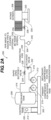
- a conventional air burst system 100 generally includes an onshore air system 102, a distributor system 104 and a submerged screen intake 106.
- onshore air system 102 will include a receiver tank 108 for storing compressed air and a burst compressor 110 that charges/fills the receiver tank 108 with the compressed air.
- the burst compressor 110 and receiver tank 108 are selected such that the compressed air within the receiver tank 108 is pressurized to within the range of 165-200 PSIA.
- Onshore air system 102 can also include a control panel 111 that allows an onshore operator to set a burst frequency for the onshore air system 102.
- the control panel 111 can include necessary components for setting the burst frequency including, for example, a digital or mechanical timer, a microprocessor based controller, a programmable logic controller or similar control element and can include an input device such as for example, a keyboard, mouse, display, touch screen display and the like.
- Distributor system 104 generally comprises a length of air supply piping 112 having an onshore end 114 that is operably connected to the receiver tank 108 and an offshore end 116 that operably connected to an airburst manifold 118 that is located within the submerged screen intake 106.
- an operator will specify a burst frequency of the onshore air system 102 using the control panel 111.
- the burst frequency can vary based on factor including, for example, the water quality in which the submerged screen intake 106 resides, the amount of solid contaminants, particles and objects within the water and time of year, for example summer versus winter when frazil ice may be present.
- the control panel 111 opens a supply valve 120 that releases pressurized air from the receiver tank 108 into the air supply piping 112. Due to the submerged location of the air supply piping 112, the pressurized air must push any accumulated water out of the air supply piping 112 prior to releasing a pressurized burst through the airburst manifold 118.
- the receiver tank 108 must be sized not only to provide the necessary pressurized burst but also to force any accumulated water from the air supply piping 112. This increases the required size and volume of the receiver tank 108, which will consequently increase costs for the air burst system 100 and possible make the air burst system 100 impractical for use in remote locations.
- air burst system 200 can comprise an onshore air system 202, a distributor system 204 and a submerged screen intake 206.
- Onshore air system 202 generally comprises a receiver tank 208, a primary compressor 210, a secondary compressor 212 and a control panel 214.
- Primary compressor 210 generally compresses air and fills receiver tank 208 for use in providing a pressurized burst of air to the distributor system 204 through a burst line 216.
- Secondary compressor 212 can be connected directly to the distributor system 204 through a purge line 218.
- the primary compressor 210 and receiver tank 208 are selected such that the compressed air within the receiver tank 208 is pressurized to within the range of 165-200 PSIA.
- the secondary compressor 212 is generally sized for the removal of accumulated water from the distributor system 204 and will be dependent upon the depth at which the distributor system 204 and submerged screen intake 206 are submerged.
- the second compressor 212 can be sized so as to provide compressed air at greater than 30-40 feet of head pressure.
- Onshore air system 202 can also include a controller 220 in the control panel 214 that allows an onshore operator to set a burst frequency for the onshore air system 202.
- the controller 220 can include necessary components for setting the burst frequency including, for example, a digital or mechanical timer, a microprocessor based controller, a programmable logic controller or similar control element and can include an input device such as for example, a keyboard, mouse, display, touch screen display and the like.
- Controller 220 will selectively open and close a purge valve 222 and a burst valve 224, located within the purge line 218 and burst line 216 respectively, so as to selectively provide purge air or burst air to the distributor system 204.
- Distributor system 204 generally comprises a length of air supply piping 226.
- the air supply piping 226 generally includes an onshore end 228 that is fluidly coupled to both the burst line 216 and the purge line 218.
- the air supply piping 226 further comprises an offshore end 230 that is operably coupled to an airburst manifold 232 that is located within the submerged screen intake 206.
- the air supply piping 226 can further comprise a supply bend 234 located between the onshore end 228 and the offshore end 230 to help ensure that the air supply piping 226 is cleared of water prior to supplying burst air to the airburst manifold 232.
- Air supply piping 226 can further comprise a pressure senor 235 proximate the offshore end 230, wherein the pressure sensor 235 can supply pressure data to the control panel 220 indicating when a pressure reading in the air supply piping 226 is equal to the pressure of the purging air supplied by the second compressor 212 such that confirmation is provided that any water in the air supply piping 226 has been removed and the air burst can be provided from the receiver tank 208.
- air supply piping 226 can further comprise a screen valve 236 located in proximity to the offshore end 230, wherein the screen valve 236 can be selectively opened and closed at the direction of the control panel 220.
- Screen valve 236 can allow air supply piping 226 to be fully pressurized throughout its length, for example, between the onshore air system 202 and the offshore end 230. As illustrated, screen valve 236 can be external to the submerged screen intake 206 or alternatively, screen valve 236 can be in proximity to the airburst manifold 232 that is located within the submerged screen intake 206.
- an operator will specify a burst frequency of the onshore air system 202 using the control panel 220.
- the burst frequency will vary based on the factors previously discussed with respect to air burst system 110 and can include, for example, water quality including the presence of solid contaminants, particles and objects within the water and time of year, for example summer versus winter when frazil ice may be present.
- the air burst system 200 of the present invention undergoes a purge cycle prior to providing pressurized air from the receiver tank 208.
- the control panel 220 causes the purge valve 222 to be opened such that the secondary compressor 212 can supply purge air through the purge line 218 and into the air supply piping 226.
- the pressure at which the secondary compressor 212 operates is dependent upon the submerged depth of the air supply piping 226 and the submerged screen intake 206.
- the head pressure of the purge air will typically be greater than 30-40 feet of head and in all cases should exceed the submerged depth of the air supply piping 226 and the submerged screen intake 206, any accumulated water within the air supply piping 226 and submerged screen intake 206 is expelled through the airburst manifold 232 such little to no water remains within the air supply piping 226 and the submerged screen intake 206.
- the pressure sensor 234 transmits a signal to the control panel 220 indicating that the pressure within the air supply piping 226 exceeds the depth pressure so as to provide the control panel 220 with confirmation that the purge cycle has been completed.
- primary compressor 210 can be operating independently as directed by the control panel 220 to fill the receiver tank 208 with pressurized air at a desired air burst pressure.
- the air supply piping 226 includes the screen valve 236, screen valve 236 can be closed following completion of the purge cycle to maintain the pressurized purge air within the air supply piping 226 until an air burst is requested.
- the control panel 220 closes the purge valve 222 and causes the burst valve 224 to open. With the burst valve 224 open, burst air from the receiver tank 208 is supplied into now evacuated distributor system 204.
- the burst air supplied from receiver tank 208 is provided at a pressure of 165-200 PSIA.
- the volume of burst air necessary to achieve a pressurized burst through the airburst manifold 232 is significantly reduced as compared to the prior art and may constitute less than half of the air volume necessary with the prior art.
- the capacity of both receiver tank 208 and primary compressor 210 can both be significantly reduced in comparison to conventional designs resulting in significant savings and making the air burst system 200 practical in some remote locations that otherwise may be impractical.
- the design capacity of receiver tank 208 can shrink by 50% or more, for example, from about 12,000 gallons to about 6,000 gallons or less leading to significant savings in both construction and transportation.
- the reduced size of the primary compressor 210 as compared to conventional designs can allow for the air burst system 200 to utilize solar power making the air burst system 200 even more advantageous for remote locations.
- the evacuation of water from the distributor system 204 during the purge cycle can allow for the offshore distance of the submerged screen intake 206 to be increased, for example, from a current maximum of about 1,500 feet offshore to an extended distance of 2-3 km offshore.
- the purge cycle allows for the diameter of the air supply piping 226 to be decreased which can lead to significant cost savings, especially when the submerged screen intake 206 is located a significant distance offshore.
- an alternative embodiment of air burst system 200 can include the addition of a secondary tank 209 that is filled by the secondary compressor 212 and which is directly connected to the purge line 218. Operation is otherwise similar to air burst system 200 but with the exception that the purge air comes from the secondary tank 209 as opposed to directly from the secondary compressor 212. This can allow the secondary compressor 212 to be reduced in size/capacity as the secondary compressor 212 can fill the secondary tank 209 over an extended time as opposed to being sized to purge all of the air supply piping 226 directly.
- secondary tank 209 is not required to be fabricated to withstand the high pressures of the receiver tank 208 and the corresponding air burst pressures such that the costs of fabricating the secondary tank 209 can be reduced.
- an alternative embodiment of an air burst system 300 can similarly make use of a purge cycle prior to providing pressurized air to the submerged screen intake 206.
- the performance and advantages of air burst system 300 can be substantially the same as air burst system 200 but using a different configuration.
- secondary compressor 212 is essentially by directly connecting the purge line 218 to a pressure regulating valve 302 that is fluidly connected to the receiver tank 208.
- the pressure regulating valve 302 bleeds the high pressure air contained within the receiver tank 208 to the desired purge pressure where it is directed into the distributor system 204.
- pressure regulating valve 302 can further perform the function of purge valve 222.
- control panel 220 closes the pressure regulating valve 302, whereby the burst valve 224 is opened and the burst air is provided from the receiver tank 208 in a manner similar to that as described with respect to air burst system 200.
- a means for purging a distributor system will generally comprise the components described relative to the purge line 218.
- the means for purging a distributor system relative to air burst system 200 will generally comprise the secondary compressor 212, the purge line 218, the purge valve 222 and the operational control provided by the control panel 220.
- the means for purging the distributor system can comprise the receiver tank 208, the purge line 218, the purge valve 222, the pressure regulating valve 302 and the operational control provided by the control panel 220.
- purge line 218 can be completely removed and pressure regulating valve 302 can be positioned within the burst line 216 such that both the purge and air burst functions are accomplished through purge line 218. In this way, capital and installation costs can be reduced in that there is no necessity for any of the components of purge line 218.
Landscapes
- Chemical Kinetics & Catalysis (AREA)
- Chemical & Material Sciences (AREA)
- Engineering & Computer Science (AREA)
- General Engineering & Computer Science (AREA)
- Environmental & Geological Engineering (AREA)
- Life Sciences & Earth Sciences (AREA)
- Hydrology & Water Resources (AREA)
- Public Health (AREA)
- Water Supply & Treatment (AREA)
- Health & Medical Sciences (AREA)
- Mechanical Engineering (AREA)
- Civil Engineering (AREA)
- Structural Engineering (AREA)
- Structures Of Non-Positive Displacement Pumps (AREA)
- Cleaning In General (AREA)
Applications Claiming Priority (2)
| Application Number | Priority Date | Filing Date | Title |
|---|---|---|---|
| US201862633036P | 2018-02-20 | 2018-02-20 | |
| PCT/US2019/018728 WO2019164913A1 (en) | 2018-02-20 | 2019-02-20 | Air burst system for cleaning submerged screen intake |
Publications (3)
| Publication Number | Publication Date |
|---|---|
| EP3755449A1 EP3755449A1 (en) | 2020-12-30 |
| EP3755449A4 EP3755449A4 (en) | 2021-10-06 |
| EP3755449B1 true EP3755449B1 (en) | 2025-05-07 |
Family
ID=67687369
Family Applications (1)
| Application Number | Title | Priority Date | Filing Date |
|---|---|---|---|
| EP19757074.0A Active EP3755449B1 (en) | 2018-02-20 | 2019-02-20 | Air burst system for cleaning submerged screen intake |
Country Status (8)
| Country | Link |
|---|---|
| US (2) | US11192068B2 (pl) |
| EP (1) | EP3755449B1 (pl) |
| CN (1) | CN112566709B (pl) |
| AU (1) | AU2019224002B2 (pl) |
| ES (1) | ES3036942T3 (pl) |
| PL (1) | PL3755449T3 (pl) |
| PT (1) | PT3755449T (pl) |
| WO (1) | WO2019164913A1 (pl) |
Families Citing this family (5)
| Publication number | Priority date | Publication date | Assignee | Title |
|---|---|---|---|---|
| GB2551317A (en) * | 2016-06-07 | 2017-12-20 | Ide Technologies Ltd | Environmentally friendly water intake and pretreatment system |
| NO348078B1 (en) * | 2017-11-06 | 2024-08-12 | Fasseland Mekaniske Verksted As | An Inlet Screen for a Hydropower Plant |
| WO2020206556A1 (en) * | 2019-04-12 | 2020-10-15 | Cameron Farms Hutterite Colony | Fluid pumping apparatus and methods of use |
| US12320087B2 (en) * | 2021-07-14 | 2025-06-03 | The United States Of America As Represented By The Secretary Of Agriculture | Submerged liquid intake strainers |
| CN114130092B (zh) * | 2021-12-09 | 2023-04-14 | 江南造船(集团)有限责任公司 | 液货舱浸没泵吸口滤网清洁方法及清洁系统 |
Family Cites Families (18)
| Publication number | Priority date | Publication date | Assignee | Title |
|---|---|---|---|---|
| US5062968A (en) * | 1987-09-14 | 1991-11-05 | Warning Theodore A | Apparatus and process for filtering fluids |
| US5558462A (en) * | 1994-12-02 | 1996-09-24 | The United States Of America As Represented By The Secretary Of The Interior | Flat plate fish screen system |
| US6673136B2 (en) * | 2000-09-05 | 2004-01-06 | Donaldson Company, Inc. | Air filtration arrangements having fluted media constructions and methods |
| US6758344B2 (en) * | 2002-02-21 | 2004-07-06 | Gordon Construction, Inc. | Self-cleaning fluid filter system |
| JP2005193214A (ja) * | 2004-01-05 | 2005-07-21 | Yamato:Kk | 生物膜・アメーバ除去装置付の濾過装置 |
| FR2869552B1 (fr) * | 2004-04-29 | 2007-04-06 | Otv Sa | Dispositif de filtration pour le traitement d'eaux, du type a membranes immergees, incluant des moyens antirefoulement du milieu a filtrer vers des moyens d'injection d'un gaz de decolmatage. |
| US7867395B2 (en) | 2005-07-25 | 2011-01-11 | Weatherford/Lamb, Inc. | Valveless intake screen airburst system |
| CN101091854A (zh) * | 2007-04-19 | 2007-12-26 | 无锡意格尔润滑科技有限公司 | 一种热过滤的方法 |
| AU2008251556A1 (en) * | 2007-05-11 | 2008-11-20 | Zenon Technology Partnership | Membrane module with multiple bottom headers and filtration process |
| AU2009282912B2 (en) * | 2008-08-20 | 2014-11-27 | Evoqua Water Technologies Llc | Improved membrane system backwash energy efficiency |
| US8470143B2 (en) * | 2010-01-26 | 2013-06-25 | Daniel Moroni Tucker | Advanced chlorine generating system |
| US20130015130A1 (en) | 2011-07-13 | 2013-01-17 | Joseph Breitner | Pulse aeration for immersed membranes |
| US9943786B2 (en) * | 2012-02-02 | 2018-04-17 | Aqseptence Group, Inc. | Screen intake cleaning system using variable flow of incompressible liquid |
| US9502144B2 (en) * | 2012-07-06 | 2016-11-22 | Westinghouse Electric Company Llc | Filter for a nuclear reactor containment ventilation system |
| WO2014103854A1 (ja) * | 2012-12-27 | 2014-07-03 | 住友電気工業株式会社 | バラスト水処理装置およびバラスト水処理装置の逆洗浄方法 |
| CN203379689U (zh) * | 2013-07-11 | 2014-01-08 | 厦门申颖科技有限公司 | 两相流冲洗装置 |
| US9215214B2 (en) | 2014-02-20 | 2015-12-15 | Nicira, Inc. | Provisioning firewall rules on a firewall enforcing device |
| CN107638729A (zh) * | 2017-11-06 | 2018-01-30 | 无锡智谷锐拓技术服务有限公司 | 一种家庭污水处理装置 |
-
2019
- 2019-02-20 WO PCT/US2019/018728 patent/WO2019164913A1/en not_active Ceased
- 2019-02-20 CN CN201980026840.6A patent/CN112566709B/zh not_active Expired - Fee Related
- 2019-02-20 ES ES19757074T patent/ES3036942T3/es active Active
- 2019-02-20 US US16/971,548 patent/US11192068B2/en active Active
- 2019-02-20 EP EP19757074.0A patent/EP3755449B1/en active Active
- 2019-02-20 AU AU2019224002A patent/AU2019224002B2/en active Active
- 2019-02-20 PT PT197570740T patent/PT3755449T/pt unknown
- 2019-02-20 PL PL19757074.0T patent/PL3755449T3/pl unknown
-
2021
- 2021-12-07 US US17/544,582 patent/US12138592B2/en active Active
Also Published As
| Publication number | Publication date |
|---|---|
| US20220105474A1 (en) | 2022-04-07 |
| US20200398226A1 (en) | 2020-12-24 |
| CN112566709A (zh) | 2021-03-26 |
| EP3755449A4 (en) | 2021-10-06 |
| EP3755449A1 (en) | 2020-12-30 |
| CN112566709B (zh) | 2022-11-04 |
| US11192068B2 (en) | 2021-12-07 |
| AU2019224002B2 (en) | 2025-04-03 |
| AU2019224002A1 (en) | 2020-10-15 |
| ES3036942T3 (en) | 2025-09-25 |
| US12138592B2 (en) | 2024-11-12 |
| WO2019164913A1 (en) | 2019-08-29 |
| PL3755449T3 (pl) | 2025-10-13 |
| PT3755449T (pt) | 2025-08-13 |
Similar Documents
| Publication | Publication Date | Title |
|---|---|---|
| EP3755449B1 (en) | Air burst system for cleaning submerged screen intake | |
| EP1485181B1 (en) | Self-cleaning fluid filter system | |
| US8075700B2 (en) | Method of cleaning a filter | |
| US6875364B2 (en) | Self-cleaning fluid filter system | |
| CN112049138A (zh) | 深基坑降水、净化、回灌一体化系统及控制方法 | |
| CN207253883U (zh) | 一种用于水利工程的管道 | |
| CN108295529A (zh) | 储能清洗海水过滤装置 | |
| JP2016104462A (ja) | 水処理装置 | |
| KR100511208B1 (ko) | 재활용 및 홍수방지용 빗물저수조 시스템 | |
| EP3052213B1 (en) | Fitlration system and method for filtering a liquid | |
| KR101267025B1 (ko) | 역세 및 세정 조절이 개별적으로 가능한 개착식 하상여과 전용 세정시스템 | |
| CN209873835U (zh) | 一种新型回灌井结构 | |
| CN107428407A (zh) | 用于对来自水体的水进行净化的系统和方法 | |
| CN207392294U (zh) | 一种全自动多级过滤雨水灌溉装置 | |
| CN221003320U (zh) | 一种用于lnapl污染场地的油水双相抽提装置及系统 | |
| CN103408155A (zh) | 水过滤装置 | |
| CN110397116A (zh) | 一种控制反冲系统 | |
| RU2574663C1 (ru) | Гидротехническое сооружение для сифонного водоотвода подземной родниковой воды | |
| JP2005169326A (ja) | フィルタ洗浄装置及び方法 | |
| CN117983652A (zh) | 用于地下水修复系统的沉淀去除系统和沉淀去除方法 | |
| CN119640062A (zh) | 风动力海水提铀系统 |
Legal Events
| Date | Code | Title | Description |
|---|---|---|---|
| STAA | Information on the status of an ep patent application or granted ep patent |
Free format text: STATUS: THE INTERNATIONAL PUBLICATION HAS BEEN MADE |
|
| PUAI | Public reference made under article 153(3) epc to a published international application that has entered the european phase |
Free format text: ORIGINAL CODE: 0009012 |
|
| STAA | Information on the status of an ep patent application or granted ep patent |
Free format text: STATUS: REQUEST FOR EXAMINATION WAS MADE |
|
| 17P | Request for examination filed |
Effective date: 20200921 |
|
| AK | Designated contracting states |
Kind code of ref document: A1 Designated state(s): AL AT BE BG CH CY CZ DE DK EE ES FI FR GB GR HR HU IE IS IT LI LT LU LV MC MK MT NL NO PL PT RO RS SE SI SK SM TR |
|
| AX | Request for extension of the european patent |
Extension state: BA ME |
|
| DAV | Request for validation of the european patent (deleted) | ||
| DAX | Request for extension of the european patent (deleted) | ||
| A4 | Supplementary search report drawn up and despatched |
Effective date: 20210903 |
|
| RIC1 | Information provided on ipc code assigned before grant |
Ipc: E03B 3/18 20060101ALI20210830BHEP Ipc: E02B 1/00 20060101ALI20210830BHEP Ipc: E03B 3/04 20060101ALI20210830BHEP Ipc: E02B 9/04 20060101ALI20210830BHEP Ipc: B01D 29/66 20060101AFI20210830BHEP |
|
| STAA | Information on the status of an ep patent application or granted ep patent |
Free format text: STATUS: EXAMINATION IS IN PROGRESS |
|
| 17Q | First examination report despatched |
Effective date: 20220722 |
|
| RAP3 | Party data changed (applicant data changed or rights of an application transferred) |
Owner name: JOHNSON SCREENS, INC. |
|
| GRAP | Despatch of communication of intention to grant a patent |
Free format text: ORIGINAL CODE: EPIDOSNIGR1 |
|
| STAA | Information on the status of an ep patent application or granted ep patent |
Free format text: STATUS: GRANT OF PATENT IS INTENDED |
|
| INTG | Intention to grant announced |
Effective date: 20240917 |
|
| GRAJ | Information related to disapproval of communication of intention to grant by the applicant or resumption of examination proceedings by the epo deleted |
Free format text: ORIGINAL CODE: EPIDOSDIGR1 |
|
| STAA | Information on the status of an ep patent application or granted ep patent |
Free format text: STATUS: EXAMINATION IS IN PROGRESS |
|
| GRAP | Despatch of communication of intention to grant a patent |
Free format text: ORIGINAL CODE: EPIDOSNIGR1 |
|
| STAA | Information on the status of an ep patent application or granted ep patent |
Free format text: STATUS: GRANT OF PATENT IS INTENDED |
|
| INTC | Intention to grant announced (deleted) | ||
| INTG | Intention to grant announced |
Effective date: 20250130 |
|
| P01 | Opt-out of the competence of the unified patent court (upc) registered |
Free format text: CASE NUMBER: APP_4419/2025 Effective date: 20250127 |
|
| GRAS | Grant fee paid |
Free format text: ORIGINAL CODE: EPIDOSNIGR3 |
|
| GRAA | (expected) grant |
Free format text: ORIGINAL CODE: 0009210 |
|
| STAA | Information on the status of an ep patent application or granted ep patent |
Free format text: STATUS: THE PATENT HAS BEEN GRANTED |
|
| AK | Designated contracting states |
Kind code of ref document: B1 Designated state(s): AL AT BE BG CH CY CZ DE DK EE ES FI FR GB GR HR HU IE IS IT LI LT LU LV MC MK MT NL NO PL PT RO RS SE SI SK SM TR |
|
| REG | Reference to a national code |
Ref country code: GB Ref legal event code: FG4D |
|
| REG | Reference to a national code |
Ref country code: CH Ref legal event code: EP |
|
| REG | Reference to a national code |
Ref country code: DE Ref legal event code: R096 Ref document number: 602019069644 Country of ref document: DE |
|
| REG | Reference to a national code |
Ref country code: IE Ref legal event code: FG4D |
|
| REG | Reference to a national code |
Ref country code: PT Ref legal event code: SC4A Ref document number: 3755449 Country of ref document: PT Date of ref document: 20250813 Kind code of ref document: T Free format text: AVAILABILITY OF NATIONAL TRANSLATION Effective date: 20250807 |
|
| REG | Reference to a national code |
Ref country code: NL Ref legal event code: FP |
|
| REG | Reference to a national code |
Ref country code: SE Ref legal event code: TRGR |
|
| REG | Reference to a national code |
Ref country code: ES Ref legal event code: FG2A Ref document number: 3036942 Country of ref document: ES Kind code of ref document: T3 Effective date: 20250925 |
|
| PG25 | Lapsed in a contracting state [announced via postgrant information from national office to epo] |
Ref country code: FI Free format text: LAPSE BECAUSE OF FAILURE TO SUBMIT A TRANSLATION OF THE DESCRIPTION OR TO PAY THE FEE WITHIN THE PRESCRIBED TIME-LIMIT Effective date: 20250507 |
|
| REG | Reference to a national code |
Ref country code: LT Ref legal event code: MG9D |
|
| PG25 | Lapsed in a contracting state [announced via postgrant information from national office to epo] |
Ref country code: NO Free format text: LAPSE BECAUSE OF FAILURE TO SUBMIT A TRANSLATION OF THE DESCRIPTION OR TO PAY THE FEE WITHIN THE PRESCRIBED TIME-LIMIT Effective date: 20250807 Ref country code: GR Free format text: LAPSE BECAUSE OF FAILURE TO SUBMIT A TRANSLATION OF THE DESCRIPTION OR TO PAY THE FEE WITHIN THE PRESCRIBED TIME-LIMIT Effective date: 20250808 |
|
| REG | Reference to a national code |
Ref country code: AT Ref legal event code: MK05 Ref document number: 1791878 Country of ref document: AT Kind code of ref document: T Effective date: 20250507 |
|
| PG25 | Lapsed in a contracting state [announced via postgrant information from national office to epo] |
Ref country code: BG Free format text: LAPSE BECAUSE OF FAILURE TO SUBMIT A TRANSLATION OF THE DESCRIPTION OR TO PAY THE FEE WITHIN THE PRESCRIBED TIME-LIMIT Effective date: 20250507 |
|
| PG25 | Lapsed in a contracting state [announced via postgrant information from national office to epo] |
Ref country code: HR Free format text: LAPSE BECAUSE OF FAILURE TO SUBMIT A TRANSLATION OF THE DESCRIPTION OR TO PAY THE FEE WITHIN THE PRESCRIBED TIME-LIMIT Effective date: 20250507 |
|
| PG25 | Lapsed in a contracting state [announced via postgrant information from national office to epo] |
Ref country code: AT Free format text: LAPSE BECAUSE OF FAILURE TO SUBMIT A TRANSLATION OF THE DESCRIPTION OR TO PAY THE FEE WITHIN THE PRESCRIBED TIME-LIMIT Effective date: 20250507 |
|
| PG25 | Lapsed in a contracting state [announced via postgrant information from national office to epo] |
Ref country code: RS Free format text: LAPSE BECAUSE OF FAILURE TO SUBMIT A TRANSLATION OF THE DESCRIPTION OR TO PAY THE FEE WITHIN THE PRESCRIBED TIME-LIMIT Effective date: 20250807 |
|
| PG25 | Lapsed in a contracting state [announced via postgrant information from national office to epo] |
Ref country code: IS Free format text: LAPSE BECAUSE OF FAILURE TO SUBMIT A TRANSLATION OF THE DESCRIPTION OR TO PAY THE FEE WITHIN THE PRESCRIBED TIME-LIMIT Effective date: 20250907 |
|
| PG25 | Lapsed in a contracting state [announced via postgrant information from national office to epo] |
Ref country code: LV Free format text: LAPSE BECAUSE OF FAILURE TO SUBMIT A TRANSLATION OF THE DESCRIPTION OR TO PAY THE FEE WITHIN THE PRESCRIBED TIME-LIMIT Effective date: 20250507 |
|
| PG25 | Lapsed in a contracting state [announced via postgrant information from national office to epo] |
Ref country code: DK Free format text: LAPSE BECAUSE OF FAILURE TO SUBMIT A TRANSLATION OF THE DESCRIPTION OR TO PAY THE FEE WITHIN THE PRESCRIBED TIME-LIMIT Effective date: 20250507 Ref country code: SM Free format text: LAPSE BECAUSE OF FAILURE TO SUBMIT A TRANSLATION OF THE DESCRIPTION OR TO PAY THE FEE WITHIN THE PRESCRIBED TIME-LIMIT Effective date: 20250507 |
|
| PG25 | Lapsed in a contracting state [announced via postgrant information from national office to epo] |
Ref country code: CZ Free format text: LAPSE BECAUSE OF FAILURE TO SUBMIT A TRANSLATION OF THE DESCRIPTION OR TO PAY THE FEE WITHIN THE PRESCRIBED TIME-LIMIT Effective date: 20250507 |
|
| PG25 | Lapsed in a contracting state [announced via postgrant information from national office to epo] |
Ref country code: EE Free format text: LAPSE BECAUSE OF FAILURE TO SUBMIT A TRANSLATION OF THE DESCRIPTION OR TO PAY THE FEE WITHIN THE PRESCRIBED TIME-LIMIT Effective date: 20250507 |
|
| PG25 | Lapsed in a contracting state [announced via postgrant information from national office to epo] |
Ref country code: SK Free format text: LAPSE BECAUSE OF FAILURE TO SUBMIT A TRANSLATION OF THE DESCRIPTION OR TO PAY THE FEE WITHIN THE PRESCRIBED TIME-LIMIT Effective date: 20250507 |