EP3755229B1 - Verfolgung einer interventionellen medizinischen vorrichtung - Google Patents
Verfolgung einer interventionellen medizinischen vorrichtung Download PDFInfo
- Publication number
- EP3755229B1 EP3755229B1 EP19707347.1A EP19707347A EP3755229B1 EP 3755229 B1 EP3755229 B1 EP 3755229B1 EP 19707347 A EP19707347 A EP 19707347A EP 3755229 B1 EP3755229 B1 EP 3755229B1
- Authority
- EP
- European Patent Office
- Prior art keywords
- medical device
- interventional medical
- imaging
- imaging plane
- interventional
- Prior art date
- Legal status (The legal status is an assumption and is not a legal conclusion. Google has not performed a legal analysis and makes no representation as to the accuracy of the status listed.)
- Active
Links
Images


Classifications
-
- A—HUMAN NECESSITIES
- A61—MEDICAL OR VETERINARY SCIENCE; HYGIENE
- A61B—DIAGNOSIS; SURGERY; IDENTIFICATION
- A61B34/00—Computer-aided surgery; Manipulators or robots specially adapted for use in surgery
- A61B34/20—Surgical navigation systems; Devices for tracking or guiding surgical instruments, e.g. for frameless stereotaxis
-
- A—HUMAN NECESSITIES
- A61—MEDICAL OR VETERINARY SCIENCE; HYGIENE
- A61B—DIAGNOSIS; SURGERY; IDENTIFICATION
- A61B8/00—Diagnosis using ultrasonic, sonic or infrasonic waves
- A61B8/08—Clinical applications
- A61B8/0833—Clinical applications involving detecting or locating foreign bodies or organic structures
- A61B8/0841—Clinical applications involving detecting or locating foreign bodies or organic structures for locating instruments
-
- A—HUMAN NECESSITIES
- A61—MEDICAL OR VETERINARY SCIENCE; HYGIENE
- A61B—DIAGNOSIS; SURGERY; IDENTIFICATION
- A61B8/00—Diagnosis using ultrasonic, sonic or infrasonic waves
- A61B8/08—Clinical applications
- A61B8/0883—Clinical applications for diagnosis of the heart
-
- A—HUMAN NECESSITIES
- A61—MEDICAL OR VETERINARY SCIENCE; HYGIENE
- A61B—DIAGNOSIS; SURGERY; IDENTIFICATION
- A61B8/00—Diagnosis using ultrasonic, sonic or infrasonic waves
- A61B8/12—Diagnosis using ultrasonic, sonic or infrasonic waves in body cavities or body tracts, e.g. by using catheters
-
- A—HUMAN NECESSITIES
- A61—MEDICAL OR VETERINARY SCIENCE; HYGIENE
- A61B—DIAGNOSIS; SURGERY; IDENTIFICATION
- A61B8/00—Diagnosis using ultrasonic, sonic or infrasonic waves
- A61B8/13—Tomography
- A61B8/14—Echo-tomography
- A61B8/145—Echo-tomography characterised by scanning multiple planes
-
- A—HUMAN NECESSITIES
- A61—MEDICAL OR VETERINARY SCIENCE; HYGIENE
- A61B—DIAGNOSIS; SURGERY; IDENTIFICATION
- A61B8/00—Diagnosis using ultrasonic, sonic or infrasonic waves
- A61B8/46—Ultrasonic, sonic or infrasonic diagnostic devices with special arrangements for interfacing with the operator or the patient
- A61B8/461—Displaying means of special interest
- A61B8/463—Displaying means of special interest characterised by displaying multiple images or images and diagnostic data on one display
-
- A—HUMAN NECESSITIES
- A61—MEDICAL OR VETERINARY SCIENCE; HYGIENE
- A61B—DIAGNOSIS; SURGERY; IDENTIFICATION
- A61B8/00—Diagnosis using ultrasonic, sonic or infrasonic waves
- A61B8/54—Control of the diagnostic device
-
- G—PHYSICS
- G01—MEASURING; TESTING
- G01S—RADIO DIRECTION-FINDING; RADIO NAVIGATION; DETERMINING DISTANCE OR VELOCITY BY USE OF RADIO WAVES; LOCATING OR PRESENCE-DETECTING BY USE OF THE REFLECTION OR RERADIATION OF RADIO WAVES; ANALOGOUS ARRANGEMENTS USING OTHER WAVES
- G01S15/00—Systems using the reflection or reradiation of acoustic waves, e.g. sonar systems
- G01S15/88—Sonar systems specially adapted for specific applications
- G01S15/89—Sonar systems specially adapted for specific applications for mapping or imaging
- G01S15/8906—Short-range imaging systems; Acoustic microscope systems using pulse-echo techniques
- G01S15/899—Combination of imaging systems with ancillary equipment
-
- G—PHYSICS
- G01—MEASURING; TESTING
- G01S—RADIO DIRECTION-FINDING; RADIO NAVIGATION; DETERMINING DISTANCE OR VELOCITY BY USE OF RADIO WAVES; LOCATING OR PRESENCE-DETECTING BY USE OF THE REFLECTION OR RERADIATION OF RADIO WAVES; ANALOGOUS ARRANGEMENTS USING OTHER WAVES
- G01S7/00—Details of systems according to groups G01S13/00, G01S15/00, G01S17/00
- G01S7/52—Details of systems according to groups G01S13/00, G01S15/00, G01S17/00 of systems according to group G01S15/00
- G01S7/52017—Details of systems according to groups G01S13/00, G01S15/00, G01S17/00 of systems according to group G01S15/00 particularly adapted to short-range imaging
- G01S7/52053—Display arrangements
- G01S7/52057—Cathode ray tube displays
- G01S7/5206—Two-dimensional coordinated display of distance and direction; B-scan display
-
- A—HUMAN NECESSITIES
- A61—MEDICAL OR VETERINARY SCIENCE; HYGIENE
- A61B—DIAGNOSIS; SURGERY; IDENTIFICATION
- A61B17/00—Surgical instruments, devices or methods
- A61B2017/00017—Electrical control of surgical instruments
- A61B2017/00203—Electrical control of surgical instruments with speech control or speech recognition
-
- A—HUMAN NECESSITIES
- A61—MEDICAL OR VETERINARY SCIENCE; HYGIENE
- A61B—DIAGNOSIS; SURGERY; IDENTIFICATION
- A61B34/00—Computer-aided surgery; Manipulators or robots specially adapted for use in surgery
- A61B34/20—Surgical navigation systems; Devices for tracking or guiding surgical instruments, e.g. for frameless stereotaxis
- A61B2034/2046—Tracking techniques
- A61B2034/2063—Acoustic tracking systems, e.g. using ultrasound
-
- A—HUMAN NECESSITIES
- A61—MEDICAL OR VETERINARY SCIENCE; HYGIENE
- A61B—DIAGNOSIS; SURGERY; IDENTIFICATION
- A61B34/00—Computer-aided surgery; Manipulators or robots specially adapted for use in surgery
- A61B34/20—Surgical navigation systems; Devices for tracking or guiding surgical instruments, e.g. for frameless stereotaxis
- A61B2034/2046—Tracking techniques
- A61B2034/2065—Tracking using image or pattern recognition
-
- A—HUMAN NECESSITIES
- A61—MEDICAL OR VETERINARY SCIENCE; HYGIENE
- A61B—DIAGNOSIS; SURGERY; IDENTIFICATION
- A61B34/00—Computer-aided surgery; Manipulators or robots specially adapted for use in surgery
- A61B34/20—Surgical navigation systems; Devices for tracking or guiding surgical instruments, e.g. for frameless stereotaxis
- A61B2034/2072—Reference field transducer attached to an instrument or patient
-
- A—HUMAN NECESSITIES
- A61—MEDICAL OR VETERINARY SCIENCE; HYGIENE
- A61B—DIAGNOSIS; SURGERY; IDENTIFICATION
- A61B90/00—Instruments, implements or accessories specially adapted for surgery or diagnosis and not covered by any of the groups A61B1/00 - A61B50/00, e.g. for luxation treatment or for protecting wound edges
- A61B90/36—Image-producing devices or illumination devices not otherwise provided for
- A61B90/37—Surgical systems with images on a monitor during operation
- A61B2090/378—Surgical systems with images on a monitor during operation using ultrasound
- A61B2090/3782—Surgical systems with images on a monitor during operation using ultrasound transmitter or receiver in catheter or minimal invasive instrument
- A61B2090/3788—Surgical systems with images on a monitor during operation using ultrasound transmitter or receiver in catheter or minimal invasive instrument transmitter only
-
- A—HUMAN NECESSITIES
- A61—MEDICAL OR VETERINARY SCIENCE; HYGIENE
- A61B—DIAGNOSIS; SURGERY; IDENTIFICATION
- A61B90/00—Instruments, implements or accessories specially adapted for surgery or diagnosis and not covered by any of the groups A61B1/00 - A61B50/00, e.g. for luxation treatment or for protecting wound edges
- A61B90/39—Markers, e.g. radio-opaque or breast lesions markers
- A61B2090/3925—Markers, e.g. radio-opaque or breast lesions markers ultrasonic
-
- A—HUMAN NECESSITIES
- A61—MEDICAL OR VETERINARY SCIENCE; HYGIENE
- A61B—DIAGNOSIS; SURGERY; IDENTIFICATION
- A61B34/00—Computer-aided surgery; Manipulators or robots specially adapted for use in surgery
- A61B34/25—User interfaces for surgical systems
Definitions
- a transesophageal echocardiography (TEE) ultrasound probe is commonly used in cardiac monitoring and navigation.
- TEE ultrasound probe Currently available multi-plane imaging modes for a TEE ultrasound probe include X-plane and full three-dimensional (3D) volume.
- Ultrasound tracking technology estimates the position of a passive ultrasound sensor (e.g., PZT, PVDF, copolymer or other piezoelectric material) in the field of view (FOV) of a diagnostic ultrasound B-mode image by analyzing the signal received by the passive ultrasound sensor as the imaging beams of the ultrasound probe sweep the field of view.
- Time-of-flight measurements provide the axial/radial distance of the passive ultrasound sensor from the imaging array, while amplitude measurements and knowledge of the beam firing sequence provide the lateral / angular position of the passive ultrasound sensor.
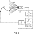
- FIG. 1 illustrates a known system for tracking an interventional medical device using a passive ultrasound sensor.
- an ultrasound probe 102 emits an imaging beam 103 that sweeps across a passive ultrasound sensor 104 on a tool tip of an interventional medical device 105.
- An image of tissue 107 is fed back by the ultrasound probe 102.
- a location of the passive ultrasound sensor 104 on the tool tip of the interventional medical device 105 is provided as a tip location 108 upon determination by a signal processing algorithm.
- the tip location 108 is overlaid on the image of tissue 107 as an overlay image 109.
- the image of tissue 107, the tip location 108, and the overlay image 109 are all displayed on a display 100.
- a document US 2012/041311 A1 relates to a system and method of three dimensional acoustic imaging for medical procedure guidance that includes receiving an acoustic signal that is scanned to interrogate a volume of interest; determining a location of a procedural device within the interrogated volume from the acoustic signal; and displaying on a display device a first view of a first plane perpendicular to an orientation of the procedural device. A second view of at least one plane perpendicular to the first plane is also displayed. A third view of a third plane perpendicular to the first plane and to the second plane is also displayed. The first, second, and third views are displayed at the same time
- use of an X-plane can provide a high frame rate, but only 2 adjustable imaging planes.
- use of a full three-dimensional (3D) volume can provide control over slicing, but a low frame rate.
- the present disclosure provides an ability to simultaneously visualize both an interventional medical device and anatomy targeted by the interventional medical device using, for example, the same ultrasound imaging probe by emitting imaging signals in three or more imaging planes.
- the simultaneous emission and capture by the ultrasound imaging probe involves emitting and capturing the interventional medical device and targeted anatomy when the interventional medical device and targeted anatomy are physically separated in a three-dimensional space.
- tissue around a device can be visualized with other quantitative navigation metrics, without losing sight of desired anatomy.
- Device tracking output can be bootstrapped to an imaging plane selection algorithm, via an automatic feedback/control loop that links device location to control of imaging plane selection.
- An example of an automatic feedback/control loop is a remote control link (RCL), which tracks an identified device through imaging planes as the device is moved.
- RCL remote control link
- the interventional device tracking is used as part of a feedback loop to ensure that the ability to track the interventional device continues, so that one or more imaging planes are tied or dedicated to the interventional device.
- device tracking can be used to automatically visually follow a device with the imaging planes, in order to continue tracking the interventional device.
- FIG. 2 is an illustrative embodiment of a general computer system, on which a method of interventional medical device tracking can be implemented, in accordance with a representative embodiment.
- the computer system 200 can include a set of instructions that can be executed to cause the computer system 200 to perform any one or more of the methods or computer based functions disclosed herein.
- the computer system 200 may operate as a standalone device or may be connected, for example, using a network 201, to other computer systems or peripheral devices.
- the computer system 200 includes a main memory 220 and a static memory 230 that can communicate with each other via a bus 208.
- Memories described herein are tangible storage mediums that can store data and executable instructions, and are non-transitory during the time instructions are stored therein.
- the term "non-transitory” is to be interpreted not as an eternal characteristic of a state, but as a characteristic of a state that will last for a period.
- the term “non-transitory” specifically disavows fleeting characteristics such as characteristics of a carrier wave or signal or other forms that exist only transitorily in any place at any time.
- a memory described herein is an article of manufacture and/or machine component.
- the computer system 200 may further include a video display unit 250, such as a liquid crystal display (LCD), an organic light emitting diode (OLED), a flat panel display, a solid-state display, or a cathode ray tube (CRT).
- a video display unit 250 such as a liquid crystal display (LCD), an organic light emitting diode (OLED), a flat panel display, a solid-state display, or a cathode ray tube (CRT).
- the computer system 200 may include an input device 260, such as a keyboard/virtual keyboard or touch-sensitive input screen or speech input with speech recognition, and a cursor control device 270, such as a mouse or touch-sensitive input screen or pad.
- the computer system 200 can also include a disk drive unit 280, a signal generation device 290, such as a speaker or remote control, and a network interface device 240.
- the disk drive unit 280 may include a computer-readable medium 282 in which one or more sets of instructions 284, e.g. software, can be embedded.
- Sets of instructions 284 can be read from the computer-readable medium 282.
- the instructions 284, when executed by a processor, can be used to perform one or more of the methods and processes as described herein.
- the instructions 284 may reside completely, or at least partially, within the main memory 220, the static memory 230, and/or within the processor 210 during execution by the computer system 200.
- the present disclosure contemplates a computer-readable medium 282 that includes instructions 284 or receives and executes instructions 184 responsive to a propagated signal; so that a device connected to a network 101 can communicate voice, video or data over the network 201. Further, the instructions 284 may be transmitted or received over the network 201 via the network interface device 240.
- the anatomy targeted by the interventional device may be designated by a user instruction, such as by using a mouse and cursor or a touch screen.
- the anatomy may be a specific position on the surface of an organ such as a heart or lung, and may be targeted by the interventional device in the sense that the interventional device is moved towards the anatomy targeted by the interventional device.
- the interventional device may also be designated by a user, but may alternatively be automatically identified and tracked, such as with the use of a sensor made of a specific material that is readily identified in ultrasound.
- a display is controlled to simultaneously display, in real-time, the interventional device and the anatomy targeted by the interventional device.
- a display may be or may include a screen on a television or on an electronic device such as a monitor.
- the monitor may be a monitor specifically provided with an ultrasound system, and may have settings specifically appropriate for visualizing imagery captured by the ultrasound system as well as related information such as information related to the captured imagery.
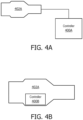
- FIG. 4A illustrates a relationship between a probe and a controller for interventional medical device tracking, in accordance with a representative embodiment.
- a probe 402A is separate from a controller 400A.
- the probe 402A is an imaging probe, and is controlled to activate imaging elements to emit imaging signals to generate imaging planes that intersect with tissue (e.g., in a patient body).
- the imaging elements may be transducer elements located on an imaging array.
- the probe 402A also captures interventional devices and anatomy targeted by the interventional devices in the imaging planes based on the response to the imaging signals (e.g., from the patient body).
- the probe 402A and controller 400A may communicate wirelessly or by wire.
- a controller 400A may include a processor 210, a main memory 220 and other elements from the computer system 200 shown in FIG. 2 .
- a controller 400A may execute instructions to perform some or all of the software-based processes described herein, such as some or all of the aspects of the method shown in FIG. 3 herein.
- Such a controller 400A may be implemented by a computer such as a dedicated ultrasound system that controls a probe 402A and receives and processes imaging data from the probe 402A.
- a controller 400A may be a distributed subsystem of both the probe 402A and a separate computer that includes the processor 210 and main memory 220 (or other memory).
- FIG. 5A shows the cross-section of the TEE (or other) ultrasound probe on the underlying cardiac anatomy.
- Active imaging planes are shown by lines of dots.
- lines of dots in the third column from the left and sixth row from the top are tied to device position, which in turn is obtained from a device tracking method.
- Lines of dots in the eighth column from the left and fourth row from the top are tied to the desired anatomy, which in turn can be set by the user. Accordingly, in the embodiment of FIG. 5A , two active imaging planes are tied to the interventional device position, and two completely different active imaging planes are tied to the desired anatomy.
- FIG. 5B illustrates a simplified view of imaging planes in the embodiment of FIG. 8A .
- the device plane #1 (vertical) 591 and the anatomy plane #1 (vertical) 596 are shown as parallel vertical lines.
- the device plane #1 (vertical) 591 and the anatomy plane #1 (vertical) 596 do not have to be parallel to each other, or vertical, as these characteristics are used as a referential convenience.
- device plane #2 (horizontal) 592 and anatomy plane #2 (horizontal) 597 are also shown as parallel lines, in this case horizontal lines.
- the device plane #2 (horizontal) 592 and anatomy plane #2 (horizontal) 597 also do not have to be parallel to each other, or horizontal, as these characteristics are also used only as a referential convenience.
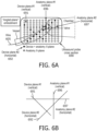
- FIG. 6A illustrates another cross section of a probe for interventional medical device tracking, in accordance with a representative embodiment.
- FIG. 6A shows an "Angled-plane" embodiment in which one X-plane is tied to device and anatomy, and one X-plane is tied to anatomy.
- a wire 605 is again overlaid on a vessel and exits the ultrasound probe cross section 690 to the left.
- a device plane #1 (vertical) 691 and a device plane #2 (horizontal) 692 correspond to the active imaging planes tied to the interventional device position, but both are rotated about an axis to tilt.
- An anatomy plane #1 (vertical) 696 and an anatomy plane #2 (horizontal) 697 correspond to the active imaging planes tied to the desired anatomy.
- the "device X-plane" is configured to image the plane containing the interventional device and the desired anatomy.
- FIG. 7A again shows the cross-section of the TEE (or other) ultrasound probe on the underlying cardiac anatomy. Active imaging planes are shown by lines of dots.
- a single line of dots in the fourth row from the top are tied to the desired anatomy.
- Lines of dots in the third column from the left and sixth row from the top are tied to device position, the same as in the embodiment of FIG. 5A and FIG. 5B described previously.
- two active imaging planes are again tied to the interventional device position, but only one completely different active imaging plane is tied to the desired anatomy.
- the anatomy imaging plane is a single plane, as opposed to a bi-plane, thereby resulting in slightly higher frame rate.
- a wire 705 is again overlaid on a vessel and exits the ultrasound probe cross section 790 to the left.
- a device plane #1 (vertical) 791 and a device plane #2 (horizontal) 792 correspond to the active imaging planes tied to the interventional device position.
- a single anatomy plane #1 (horizontal) 797 corresponds to the active imaging plane tied to the desired anatomy.
- the anatomy plane #1 (horizontal) 797 is one and the only one imaging plane dedicated to the desired anatomy in the embodiment of FIG. 7A .
- the one anatomy plane #1 (horizontal) 797 can be a short-axis imaging plane rather than a long-axis imaging plane.
- a single X-plane may be assigned to anatomy, and a single plane assigned to the device.
- FIG. 7B illustrates a simplified view of imaging planes in the embodiment of FIG. 7A .
- the device plane #1 (vertical) 791 is perpendicular or substantially perpendicular to the device plane #2 (horizontal) 792, and the anatomy plane #1 (horizontal) 797 has no corresponding vertical anatomy plane.
- FIG. 8A shows a "Floodlight”/"look ahead” embodiment in which the transverse plane of the interventional device X-plane is positioned 'x' mm ahead of the tip, to show the "upcoming" anatomy if the interventional device is pushed further.
- FIG. 8B illustrates a simplified view of imaging planes in the embodiment of FIG. 8A .
- the various planes are similar to those shown in the embodiment of FIG. 5B .
- the device plane #1 (vertical) 891 and the device plane #2 (horizontal) 592 are shown to be perpendicular or substantially perpendicular, and the anatomy plane #1 (vertical) 896 and anatomy plane #2 (horizontal) 897 are also shown to be perpendicular or substantially perpendicular.
- the device plane #1 (vertical) 891 can be projected based on the position and directionality of the interventional tool, so that the device plane #1 (vertical) 891 can be automatically controlled using feedback from the historical movement and positioning of the interventional tool.
- An example of projecting for the embodiments of FIG. 8A and FIG. 8B includes taking the angles of movement over time relative to a vertical axis, a horizontal axis, and a depth axis, particularly if the most recent movement is in a straight line or anything close to a straight line.
- the projecting can also take into account speed of movement, such as millimeters per second, in order to identify how far ahead of a current position to target for the anatomy plane #1 (vertical) 896.
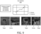
- FIG.9 illustrates views presented on a user interface for interventional medical device tracking, in accordance with a representative embodiment.
- “Distance to target” embodiment Display distance to anatomical target imaging plane on the interventional device X-plane.
- a "distance to target” can be calculated from the current device location and the desired anatomical target, and shown to the user in real-time. This is shown in Figure 9 in conjunction with a sample user interface 999.
- interventional medical device tracking enables selective use of different numbers of imaging planes in order to simultaneously capture both an interventional device and anatomy targeted by the interventional device. This provides visualization of tissue around a device and other quantitative navigation metrics, without losing sight of targeted anatomy.
- interventional medical device tracking has been described with reference to particular means, materials and embodiments, interventional medical device tracking is not intended to be limited to the particulars disclosed; rather interventional medical device tracking extends to all functionally equivalent structures, methods, and uses such as are within the scope of the appended claims.
Landscapes
- Health & Medical Sciences (AREA)
- Life Sciences & Earth Sciences (AREA)
- Engineering & Computer Science (AREA)
- Physics & Mathematics (AREA)
- Surgery (AREA)
- Veterinary Medicine (AREA)
- Public Health (AREA)
- Nuclear Medicine, Radiotherapy & Molecular Imaging (AREA)
- Biomedical Technology (AREA)
- Heart & Thoracic Surgery (AREA)
- Medical Informatics (AREA)
- Molecular Biology (AREA)
- General Health & Medical Sciences (AREA)
- Animal Behavior & Ethology (AREA)
- Radiology & Medical Imaging (AREA)
- Pathology (AREA)
- Biophysics (AREA)
- Radar, Positioning & Navigation (AREA)
- Remote Sensing (AREA)
- Acoustics & Sound (AREA)
- Computer Networks & Wireless Communication (AREA)
- General Physics & Mathematics (AREA)
- Robotics (AREA)
- Cardiology (AREA)
- Ultra Sonic Daignosis Equipment (AREA)
- Surgical Instruments (AREA)
Claims (10)
- System zum Verfolgen einer interventionellen medizinischen Vorrichtung in einem Patienten, umfassend:eine Bildgebungssonde (102, 402A), die konfiguriert ist, um Bildgebungselemente zu aktivieren, um Bildgebungsstrahlen (103) auszusenden, um vier oder mehr Bildgebungsebenen (591, 592, 596, 597, 691, 692, 696, 697) innerhalb eines Sichtfelds zu erzeugen, das eine erste Bildgebungsebene, eine zweite Bildgebungsebene, eine dritte Bildgebungsebene senkrecht zur zweiten Bildgebungsebene und eine vierte Bildgebungsebene senkrecht zur ersten Bildgebungsebene beinhaltet, um die interventionelle medizinische Vorrichtung (105) und die von der interventionellen medizinischen Vorrichtung (105) anvisierte Anatomie gleichzeitig aufzunehmen; undeine Steuereinheit (400A, 400B), die konfiguriert ist, um die Bildgebungssonde (102, 402A) zu steuern, um gleichzeitig beide, die interventionelle medizinische Vorrichtung (105) und die von der interventionellen medizinischen Vorrichtung (105) anvisierte Anatomie aufzunehmen, wobei die interventionelle medizinische Vorrichtung und die anvisierte Anatomie in einem dreidimensionalen Raum physisch getrennt sind, wobei die Bildgebungssonde (102, 402A) gesteuert wird, um mindestens eine von der interventionellen medizinischen Vorrichtung (105) und der von der interventionellen medizinischen Vorrichtung (105) anvisierten Anatomie in mindestens zwei der vier oder mehr Bildgebungsebenen (591, 592, 596, 597, 691, 692, 696, 697) aufzunehmen, und die andere von der interventionellen medizinischen Vorrichtung (105) und der von der interventionellen medizinischen Vorrichtung (105) anvisierten Anatomie in mindestens einer der vier oder mehr Bildgebungsebenen (591, 592, 596, 597, 691, 692, 696, 697) aufzunehmen, wobei die Steuereinheit (400A, 400B) einen Signalprozessor beinhaltet, der Bildsignale verarbeitet, die gleichzeitig mindestens eine von der interventionellen medizinischen Vorrichtung (105) und der von der interventionellen medizinischen Vorrichtung (105) anvisierten Anatomie in mindestens zwei der vier oder mehr Bildgebungsebenen (591, 592, 596, 597, 691, 692, 696, 697) und die andere von der interventionellen medizinischen Vorrichtung (105) und der von der interventionellen medizinischen Vorrichtung (105) anvisierten Anatomie in mindestens einer der vier oder mehr Bildgebungsebenen (591, 592, 596, 597, 691, 692, 696, 697) aufnehmen;wobei das Steuern der Bildgebungssonde (102, 402A), um die interventionelle medizinische Vorrichtung (105) aufzunehmen, das automatische Verfolgen der interventionellen medizinischen Vorrichtung mit der/den jeweiligen Bildgebungsebene(n) basierend auf verfolgten Positionen der interventionellen medizinischen Vorrichtung (105) umfasst, die durch Analysieren von Ultraschallsignalen bestimmt werden, die von einem passiven Ultraschallsensor (104) empfangen werden, der an der interventionellen medizinischen Vorrichtung (105) angeordnet ist, während die Bildgebungsstrahlen der Ultraschallsonde (102, 402A) das Sichtfeld durchsuchen; undwobei die zweite Bildgebungsebene und die dritte Bildgebungsebene zum Aufnehmen der interventionellen medizinischen Vorrichtung (105) vorgesehen sind, unddie erste Bildgebungsebene und die vierte Bildgebungsebene zum Aufnehmen der von der interventionellen medizinischen Vorrichtung (105) anvisierten Anatomie vorgesehen sind.
- System nach Anspruch 1,
wobei die Bildgebungssonde (102, 402A) eine transösophageale Echokardiographie-, (TEE)-Ultraschallsonde umfasst. - System nach Anspruch 1, das weiter eine Anzeige umfasst, und wobei die Steuereinheit (400A, 400B) weiter konfiguriert ist, um die Anzeige zu steuern, um die interventionelle medizinische Vorrichtung (105) und die von der interventionellen medizinischen Vorrichtung (105) anvisierte Anatomie gleichzeitig in Echtzeit anzuzeigen.
- System nach Anspruch 1, wobei die erste Bildgebungsebene und die zweite Bildgebungsebene im Wesentlichen parallel sind, und
wobei die dritte Bildgebungsebene und die vierte Bildgebungsebene im Wesentlichen parallel sind. - System nach Anspruch 1, wobei die zweite Bildgebungsebene und die dritte Bildgebungsebene konfiguriert sind, um beide, die interventionelle medizinische Vorrichtung (105) und die von der interventionellen medizinischen Vorrichtung (105) anvisierte Anatomie aufzunehmen.
- System nach Anspruch 1, wobei die Steuereinheit (400A, 400B) weiter konfiguriert ist, um die Bildgebungssonde (102, 402A) zu steuern, um die vierte Bildgebungsebene und die erste Bildgebungsebene um eine Achse zu drehen, um die vierte Bildgebungsebene und die erste Bildgebungsebene in Bezug zur zweiten Bildgebungsebene und der dritten Bildgebungsebene zu neigen.
- System nach Anspruch 1, wobei die vierte Bildgebungsebene für die interventionelle medizinische Vorrichtung (105) vorgesehen ist, und
wobei die vierte Bildgebungsebene angepasst ist, um einen Bereich der von der interventionellen Vorrichtung (105) anvisierten Anatomie, die basierend auf Bewegung der interventionellen medizinischen Vorrichtung (105) und einer aktuellen Position der interventionellen medizinischen Vorrichtung (105) projiziert wird, abzubilden. - Computerprogramm zum Verfolgen einer interventionellen medizinischen Vorrichtung (105) in einem Patienten, wobei das Programm Anweisungen umfasst, die, wenn sie von der Steuereinheit des Systems nach Anspruch 1 ausgeführt werden, die Steuereinheit veranlassen, die folgenden Schritte durchzuführen:Aussenden von Bildgebungssignalen durch Aktivieren von Bildgebungselementen, die von der Bildgebungssonde (102, 402A) gesteuert werden, um vier oder mehr Bildgebungsebenen (591, 592, 596, 597, 691, 692, 696, 697) innerhalb eines Sichtfelds zu erzeugen, das die erste Bildgebungsebene, die zweite Bildgebungsebene, die dritte Bildgebungsebene senkrecht zu der zweiten Bildgebungsebene und die vierte Bildgebungsebene senkrecht zu der ersten Bildgebungsebene beinhaltet, um die interventionelle medizinische Vorrichtung (105) und die von der interventionellen medizinischen Vorrichtung (105) anvisierte Anatomie gleichzeitig aufzunehmen, wobei die interventionelle medizinische Vorrichtung (105) und die anvisierte Anatomie physisch in einem dreidimensionalen Raum getrennt sind; und
gleichzeitig Aufnehmen der interventionellen medizinischen Vorrichtung und der von der interventionellen medizinischen Vorrichtung anvisierten Anatomie, wobei die Bildgebungssonde (102, 402A) gesteuert wird, um mindestens eines von der interventionellen medizinischen Vorrichtung und der von der interventionellen medizinischen Vorrichtung anvisierten Anatomie in mindestens zwei der vier oder mehr Bildgebungsebenen (591, 592, 596, 597, 691, 692, 696, 697) aufzunehmen, und um das andere von der interventionellen medizinischen Vorrichtung und der von der interventionellen medizinischen Vorrichtung anvisierten Anatomie in mindestens einer der vier oder mehr Bildgebungsebenen (591, 592, 596, 597, 691, 692, 696, 697) aufzunehmen;wobei das Steuern der Bildgebungssonde (102, 402A), um die interventionelle medizinische Vorrichtung aufzunehmen, das automatische Verfolgen der interventionellen medizinischen Vorrichtung mit der/den jeweiligen Bildgebungsebene(n) basierend auf verfolgten Positionen der interventionellen medizinischen Vorrichtung umfasst, die durch Analysieren von Ultraschallsignalen bestimmt werden, die vom passiven Ultraschallsensor (104) empfangen werden, der an der interventionellen medizinischen Vorrichtung angeordnet ist, während die Bildgebungsstrahlen der Ultraschallsonde (102, 402A) das Sichtfeld durchsuchen; undwobei die zweite Bildgebungsebene und die dritte Bildgebungsebene zum Aufnehmen der interventionellen medizinischen Vorrichtung (105) vorgesehen sind, unddie erste Bildgebungsebene und die vierte Bildgebungsebene zum Aufnehmen der von der interventionellen medizinischen Vorrichtung (105) anvisierten Anatomie vorgesehen sind. - Verfahren nach Anspruch 8, weiter umfassend:Identifizieren in einem vorbestimmten Koordinatensystem einer Position der interventionellen medizinischen Vorrichtung und einer Position der von der interventionellen medizinischen Vorrichtung anvisierten Anatomie, undHerstellen eines Abstands zwischen der Position der interventionellen medizinischen Vorrichtung und der Position der von der interventionellen medizinischen Vorrichtung anvisierten Anatomie.
- Verfahren nach Anspruch 8, weiter umfassend:
gleichzeitig Anzeigen der interventionellen medizinischen Vorrichtung und der von der interventionellen medizinischen Vorrichtung anvisierten Anatomie basierend auf dem gleichzeitigen Aufnehmen der interventionellen medizinischen Vorrichtung und der von der interventionellen medizinischen Vorrichtung anvisierten Anatomie.
Applications Claiming Priority (2)
| Application Number | Priority Date | Filing Date | Title |
|---|---|---|---|
| US201862633788P | 2018-02-22 | 2018-02-22 | |
| PCT/EP2019/054399 WO2019162422A1 (en) | 2018-02-22 | 2019-02-22 | Interventional medical device tracking |
Publications (2)
| Publication Number | Publication Date |
|---|---|
| EP3755229A1 EP3755229A1 (de) | 2020-12-30 |
| EP3755229B1 true EP3755229B1 (de) | 2025-04-09 |
Family
ID=65529694
Family Applications (1)
| Application Number | Title | Priority Date | Filing Date |
|---|---|---|---|
| EP19707347.1A Active EP3755229B1 (de) | 2018-02-22 | 2019-02-22 | Verfolgung einer interventionellen medizinischen vorrichtung |
Country Status (5)
| Country | Link |
|---|---|
| US (1) | US20200390505A1 (de) |
| EP (1) | EP3755229B1 (de) |
| JP (1) | JP7299228B2 (de) |
| CN (1) | CN111757704B (de) |
| WO (1) | WO2019162422A1 (de) |
Families Citing this family (3)
| Publication number | Priority date | Publication date | Assignee | Title |
|---|---|---|---|---|
| JP7177965B2 (ja) * | 2019-08-15 | 2022-11-24 | コーニンクレッカ フィリップス エヌ ヴェ | 操縦可能な多平面超音波撮像システム |
| EP3808279A1 (de) * | 2019-10-14 | 2021-04-21 | Koninklijke Philips N.V. | Steuerbares mehrebenen-ultraschallbildgebungssystem |
| WO2023242072A1 (en) * | 2022-06-17 | 2023-12-21 | Koninklijke Philips N.V. | Supplemented ultrasound |
Family Cites Families (22)
| Publication number | Priority date | Publication date | Assignee | Title |
|---|---|---|---|---|
| JP2743008B2 (ja) * | 1989-03-20 | 1998-04-22 | 株式会社日立メディコ | 超音波診断装置 |
| JP3662827B2 (ja) * | 2000-10-02 | 2005-06-22 | アロカ株式会社 | 超音波探触子及び超音波診断装置 |
| US8123691B2 (en) * | 2003-08-19 | 2012-02-28 | Kabushiki Kaisha Toshiba | Ultrasonic diagnostic apparatus for fixedly displaying a puncture probe during 2D imaging |
| US7940972B2 (en) * | 2007-05-16 | 2011-05-10 | General Electric Company | System and method of extended field of view image acquisition of an imaged subject |
| WO2010073165A1 (en) * | 2008-12-23 | 2010-07-01 | Koninklijke Philips Electronics, N.V. | Automated three dimensional acoustic imaging for medical procedure guidance |
| CN102869308B (zh) * | 2010-05-03 | 2015-04-29 | 皇家飞利浦电子股份有限公司 | 用于对介入工具上的(一个或多个)超声换能器进行超声跟踪的设备和方法 |
| CN103607959B (zh) * | 2011-04-21 | 2016-07-27 | 皇家飞利浦有限公司 | 用于三维超声中导管的可视化的mpr 切片选择 |
| WO2012172458A1 (en) * | 2011-06-13 | 2012-12-20 | Koninklijke Philips Electronics N.V. | Three-dimensional needle localization with a two-dimensional imaging probe |
| JP2013081764A (ja) * | 2011-09-27 | 2013-05-09 | Toshiba Corp | 超音波診断装置及び超音波走査プログラム |
| WO2013116240A1 (en) * | 2012-01-30 | 2013-08-08 | Inneroptic Technology, Inc. | Multiple medical device guidance |
| JP2013240369A (ja) * | 2012-05-17 | 2013-12-05 | Toshiba Corp | 超音波診断装置及び制御プログラム |
| US20140296694A1 (en) * | 2013-04-02 | 2014-10-02 | General Electric Company | Method and system for ultrasound needle guidance |
| CN111973225B (zh) * | 2014-01-02 | 2024-09-17 | 皇家飞利浦有限公司 | 相对超声成像平面的仪器对准和跟踪 |
| US20160324584A1 (en) * | 2014-01-02 | 2016-11-10 | Koninklijke Philips N.V. | Ultrasound navigation/tissue characterization combination |
| EP3116403B1 (de) * | 2014-03-11 | 2019-11-13 | Koninklijke Philips N.V. | Bildregistrierung und -führung mit gleichzeitiger x-ebenen-abbildung |
| CN106535774B (zh) * | 2014-07-16 | 2020-08-25 | 皇家飞利浦有限公司 | 在针对介入流程的3d成像工作流中的智能实时工具和解剖结构可视化 |
| JP6365121B2 (ja) * | 2014-08-28 | 2018-08-01 | コニカミノルタ株式会社 | 超音波探触子及び超音波診断装置 |
| EP3220828B1 (de) * | 2014-11-18 | 2021-12-22 | C.R. Bard, Inc. | Ultraschallbildgebungssystem mit automatischer bilddarstellung |
| EP3220829B1 (de) * | 2014-11-18 | 2022-03-09 | C. R. Bard, Inc. | Ultraschallbildgebungssystem mit automatischer bilddarstellung |
| EP3236859B1 (de) * | 2014-12-24 | 2021-03-31 | Koninklijke Philips N.V. | Nadelwegvorhersage zur zielbiopsie |
| JP7014517B2 (ja) * | 2016-02-26 | 2022-02-01 | キヤノンメディカルシステムズ株式会社 | 超音波診断装置及び画像処理プログラム |
| JP6714927B2 (ja) * | 2016-06-23 | 2020-07-01 | 本多電子株式会社 | 超音波画像表示装置及び方法、並びにプログラムを格納した記録媒体 |
-
2019
- 2019-02-22 JP JP2020544411A patent/JP7299228B2/ja active Active
- 2019-02-22 EP EP19707347.1A patent/EP3755229B1/de active Active
- 2019-02-22 US US16/971,030 patent/US20200390505A1/en active Pending
- 2019-02-22 WO PCT/EP2019/054399 patent/WO2019162422A1/en not_active Ceased
- 2019-02-22 CN CN201980014901.7A patent/CN111757704B/zh active Active
Also Published As
| Publication number | Publication date |
|---|---|
| EP3755229A1 (de) | 2020-12-30 |
| US20200390505A1 (en) | 2020-12-17 |
| WO2019162422A1 (en) | 2019-08-29 |
| CN111757704A (zh) | 2020-10-09 |
| JP7299228B2 (ja) | 2023-06-27 |
| CN111757704B (zh) | 2025-01-17 |
| JP2021514266A (ja) | 2021-06-10 |
Similar Documents
| Publication | Publication Date | Title |
|---|---|---|
| US10881378B2 (en) | Methods and systems for a display interface for diagnostic medical imaging | |
| KR101140525B1 (ko) | 촬상 영역 확장 방법 | |
| JP7218293B2 (ja) | 装置追跡に対する超音波システムにおける経路追跡 | |
| JP6053766B2 (ja) | 二次元撮像プローブを用いる三次元針位置特定 | |
| US20230031014A1 (en) | Synchronized tracking of multiple interventional medical devices | |
| JP2020524012A (ja) | 超音波システム及び方法 | |
| JP6629031B2 (ja) | 超音波診断装置及び医用画像診断装置 | |
| EP3755229B1 (de) | Verfolgung einer interventionellen medizinischen vorrichtung | |
| JP7171948B2 (ja) | 対象の移動を追跡するための超音波システム及び方法 | |
| CN103327905B (zh) | 手术器械的三维超声引导 | |
| EP3826542B1 (de) | Ultraschallsystem und verfahren für geführte scherwellenelastografie von anisotropem gewebe | |
| JP2021514266A5 (de) | ||
| EP3840661B1 (de) | 3d-verfolgung von interventionellen medizinischen vorrichtungen | |
| JP7488186B2 (ja) | センサベースの形状特定 | |
| KR20250002062A (ko) | 초음파 진단 장치 및 초음파 진단 장치 제어 방법 | |
| US11660064B2 (en) | Intravascular ultrasound position identification | |
| EP3986549A1 (de) | Vorrichtung und verfahren zur vorbereitung einer behandlung eines patienten mit hochintensivem fokussiertem ultraschall | |
| JP2021526932A (ja) | 相対的な装置の向きの決定 | |
| JP2022536625A (ja) | 介入医療処置のための受動型超音波センサの区別 |
Legal Events
| Date | Code | Title | Description |
|---|---|---|---|
| STAA | Information on the status of an ep patent application or granted ep patent |
Free format text: STATUS: UNKNOWN |
|
| STAA | Information on the status of an ep patent application or granted ep patent |
Free format text: STATUS: THE INTERNATIONAL PUBLICATION HAS BEEN MADE |
|
| PUAI | Public reference made under article 153(3) epc to a published international application that has entered the european phase |
Free format text: ORIGINAL CODE: 0009012 |
|
| STAA | Information on the status of an ep patent application or granted ep patent |
Free format text: STATUS: REQUEST FOR EXAMINATION WAS MADE |
|
| 17P | Request for examination filed |
Effective date: 20200922 |
|
| AK | Designated contracting states |
Kind code of ref document: A1 Designated state(s): AL AT BE BG CH CY CZ DE DK EE ES FI FR GB GR HR HU IE IS IT LI LT LU LV MC MK MT NL NO PL PT RO RS SE SI SK SM TR |
|
| AX | Request for extension of the european patent |
Extension state: BA ME |
|
| DAV | Request for validation of the european patent (deleted) | ||
| DAX | Request for extension of the european patent (deleted) | ||
| STAA | Information on the status of an ep patent application or granted ep patent |
Free format text: STATUS: EXAMINATION IS IN PROGRESS |
|
| 17Q | First examination report despatched |
Effective date: 20220103 |
|
| GRAP | Despatch of communication of intention to grant a patent |
Free format text: ORIGINAL CODE: EPIDOSNIGR1 |
|
| STAA | Information on the status of an ep patent application or granted ep patent |
Free format text: STATUS: GRANT OF PATENT IS INTENDED |
|
| RIN1 | Information on inventor provided before grant (corrected) |
Inventor name: JAIN, AMEET, KUMAR Inventor name: ERKAMP, RAMON, QUIDO Inventor name: VIGNON, FRANCOIS, GUY, GERARD, MARIE Inventor name: VAIDYA, KUNAL Inventor name: CHEN, ALVIN Inventor name: BHARAT, SHYAM |
|
| INTG | Intention to grant announced |
Effective date: 20241023 |
|
| RIN1 | Information on inventor provided before grant (corrected) |
Inventor name: JAIN, AMEET, KUMAR Inventor name: ERKAMP, RAMON, QUIDO Inventor name: VIGNON, FRANCOIS, GUY, GERARD, MARIE Inventor name: VAIDYA, KUNAL Inventor name: CHEN, ALVIN Inventor name: BHARAT, SHYAM |
|
| GRAS | Grant fee paid |
Free format text: ORIGINAL CODE: EPIDOSNIGR3 |
|
| GRAA | (expected) grant |
Free format text: ORIGINAL CODE: 0009210 |
|
| STAA | Information on the status of an ep patent application or granted ep patent |
Free format text: STATUS: THE PATENT HAS BEEN GRANTED |
|
| AK | Designated contracting states |
Kind code of ref document: B1 Designated state(s): AL AT BE BG CH CY CZ DE DK EE ES FI FR GB GR HR HU IE IS IT LI LT LU LV MC MK MT NL NO PL PT RO RS SE SI SK SM TR |
|
| REG | Reference to a national code |
Ref country code: GB Ref legal event code: FG4D |
|
| REG | Reference to a national code |
Ref country code: CH Ref legal event code: EP |
|
| REG | Reference to a national code |
Ref country code: DE Ref legal event code: R096 Ref document number: 602019068375 Country of ref document: DE |
|
| REG | Reference to a national code |
Ref country code: IE Ref legal event code: FG4D |
|
| REG | Reference to a national code |
Ref country code: NL Ref legal event code: MP Effective date: 20250409 |
|
| PG25 | Lapsed in a contracting state [announced via postgrant information from national office to epo] |
Ref country code: NL Free format text: LAPSE BECAUSE OF FAILURE TO SUBMIT A TRANSLATION OF THE DESCRIPTION OR TO PAY THE FEE WITHIN THE PRESCRIBED TIME-LIMIT Effective date: 20250409 |
|
| REG | Reference to a national code |
Ref country code: AT Ref legal event code: MK05 Ref document number: 1782786 Country of ref document: AT Kind code of ref document: T Effective date: 20250409 |
|
| PG25 | Lapsed in a contracting state [announced via postgrant information from national office to epo] |
Ref country code: FI Free format text: LAPSE BECAUSE OF FAILURE TO SUBMIT A TRANSLATION OF THE DESCRIPTION OR TO PAY THE FEE WITHIN THE PRESCRIBED TIME-LIMIT Effective date: 20250409 Ref country code: PT Free format text: LAPSE BECAUSE OF FAILURE TO SUBMIT A TRANSLATION OF THE DESCRIPTION OR TO PAY THE FEE WITHIN THE PRESCRIBED TIME-LIMIT Effective date: 20250811 Ref country code: ES Free format text: LAPSE BECAUSE OF FAILURE TO SUBMIT A TRANSLATION OF THE DESCRIPTION OR TO PAY THE FEE WITHIN THE PRESCRIBED TIME-LIMIT Effective date: 20250409 |
|
| REG | Reference to a national code |
Ref country code: LT Ref legal event code: MG9D |
|
| PG25 | Lapsed in a contracting state [announced via postgrant information from national office to epo] |
Ref country code: NO Free format text: LAPSE BECAUSE OF FAILURE TO SUBMIT A TRANSLATION OF THE DESCRIPTION OR TO PAY THE FEE WITHIN THE PRESCRIBED TIME-LIMIT Effective date: 20250709 Ref country code: GR Free format text: LAPSE BECAUSE OF FAILURE TO SUBMIT A TRANSLATION OF THE DESCRIPTION OR TO PAY THE FEE WITHIN THE PRESCRIBED TIME-LIMIT Effective date: 20250710 |
|
| PG25 | Lapsed in a contracting state [announced via postgrant information from national office to epo] |
Ref country code: PL Free format text: LAPSE BECAUSE OF FAILURE TO SUBMIT A TRANSLATION OF THE DESCRIPTION OR TO PAY THE FEE WITHIN THE PRESCRIBED TIME-LIMIT Effective date: 20250409 |
|
| PG25 | Lapsed in a contracting state [announced via postgrant information from national office to epo] |
Ref country code: BG Free format text: LAPSE BECAUSE OF FAILURE TO SUBMIT A TRANSLATION OF THE DESCRIPTION OR TO PAY THE FEE WITHIN THE PRESCRIBED TIME-LIMIT Effective date: 20250409 |
|
| PG25 | Lapsed in a contracting state [announced via postgrant information from national office to epo] |
Ref country code: HR Free format text: LAPSE BECAUSE OF FAILURE TO SUBMIT A TRANSLATION OF THE DESCRIPTION OR TO PAY THE FEE WITHIN THE PRESCRIBED TIME-LIMIT Effective date: 20250409 |
|
| PG25 | Lapsed in a contracting state [announced via postgrant information from national office to epo] |
Ref country code: AT Free format text: LAPSE BECAUSE OF FAILURE TO SUBMIT A TRANSLATION OF THE DESCRIPTION OR TO PAY THE FEE WITHIN THE PRESCRIBED TIME-LIMIT Effective date: 20250409 |
|
| PG25 | Lapsed in a contracting state [announced via postgrant information from national office to epo] |
Ref country code: RS Free format text: LAPSE BECAUSE OF FAILURE TO SUBMIT A TRANSLATION OF THE DESCRIPTION OR TO PAY THE FEE WITHIN THE PRESCRIBED TIME-LIMIT Effective date: 20250709 |
|
| PG25 | Lapsed in a contracting state [announced via postgrant information from national office to epo] |
Ref country code: IS Free format text: LAPSE BECAUSE OF FAILURE TO SUBMIT A TRANSLATION OF THE DESCRIPTION OR TO PAY THE FEE WITHIN THE PRESCRIBED TIME-LIMIT Effective date: 20250809 |
|
| PG25 | Lapsed in a contracting state [announced via postgrant information from national office to epo] |
Ref country code: LV Free format text: LAPSE BECAUSE OF FAILURE TO SUBMIT A TRANSLATION OF THE DESCRIPTION OR TO PAY THE FEE WITHIN THE PRESCRIBED TIME-LIMIT Effective date: 20250409 |