EP3754237B1 - Elektrisches ventil und herstellungsverfahren dafür - Google Patents
Elektrisches ventil und herstellungsverfahren dafür Download PDFInfo
- Publication number
- EP3754237B1 EP3754237B1 EP18906699.6A EP18906699A EP3754237B1 EP 3754237 B1 EP3754237 B1 EP 3754237B1 EP 18906699 A EP18906699 A EP 18906699A EP 3754237 B1 EP3754237 B1 EP 3754237B1
- Authority
- EP
- European Patent Office
- Prior art keywords
- valve
- component
- wall
- valve needle
- guide
- Prior art date
- Legal status (The legal status is an assumption and is not a legal conclusion. Google has not performed a legal analysis and makes no representation as to the accuracy of the status listed.)
- Active
Links
Images

Classifications
-
- F—MECHANICAL ENGINEERING; LIGHTING; HEATING; WEAPONS; BLASTING
- F16—ENGINEERING ELEMENTS AND UNITS; GENERAL MEASURES FOR PRODUCING AND MAINTAINING EFFECTIVE FUNCTIONING OF MACHINES OR INSTALLATIONS; THERMAL INSULATION IN GENERAL
- F16K—VALVES; TAPS; COCKS; ACTUATING-FLOATS; DEVICES FOR VENTING OR AERATING
- F16K1/00—Lift valves or globe valves, i.e. cut-off apparatus with closure members having at least a component of their opening and closing motion perpendicular to the closing faces
- F16K1/32—Details
- F16K1/54—Arrangements for modifying the way in which the rate of flow varies during the actuation of the valve
-
- F—MECHANICAL ENGINEERING; LIGHTING; HEATING; WEAPONS; BLASTING
- F25—REFRIGERATION OR COOLING; COMBINED HEATING AND REFRIGERATION SYSTEMS; HEAT PUMP SYSTEMS; MANUFACTURE OR STORAGE OF ICE; LIQUEFACTION SOLIDIFICATION OF GASES
- F25B—REFRIGERATION MACHINES, PLANTS OR SYSTEMS; COMBINED HEATING AND REFRIGERATION SYSTEMS; HEAT PUMP SYSTEMS
- F25B41/00—Fluid-circulation arrangements
- F25B41/30—Expansion means; Dispositions thereof
- F25B41/31—Expansion valves
- F25B41/34—Expansion valves with the valve member being actuated by electric means, e.g. by piezoelectric actuators
- F25B41/35—Expansion valves with the valve member being actuated by electric means, e.g. by piezoelectric actuators by rotary motors, e.g. by stepping motors
-
- B—PERFORMING OPERATIONS; TRANSPORTING
- B23—MACHINE TOOLS; METAL-WORKING NOT OTHERWISE PROVIDED FOR
- B23K—SOLDERING OR UNSOLDERING; WELDING; CLADDING OR PLATING BY SOLDERING OR WELDING; CUTTING BY APPLYING HEAT LOCALLY, e.g. FLAME CUTTING; WORKING BY LASER BEAM
- B23K37/00—Auxiliary devices or processes, not specially adapted for a procedure covered by only one of the other main groups of this subclass
- B23K37/04—Auxiliary devices or processes, not specially adapted for a procedure covered by only one of the other main groups of this subclass for holding or positioning work
-
- B—PERFORMING OPERATIONS; TRANSPORTING
- B23—MACHINE TOOLS; METAL-WORKING NOT OTHERWISE PROVIDED FOR
- B23P—METAL-WORKING NOT OTHERWISE PROVIDED FOR; COMBINED OPERATIONS; UNIVERSAL MACHINE TOOLS
- B23P15/00—Making specific metal objects by operations not covered by a single other subclass or a group in this subclass
- B23P15/001—Making specific metal objects by operations not covered by a single other subclass or a group in this subclass valves or valve housings
-
- F—MECHANICAL ENGINEERING; LIGHTING; HEATING; WEAPONS; BLASTING
- F16—ENGINEERING ELEMENTS AND UNITS; GENERAL MEASURES FOR PRODUCING AND MAINTAINING EFFECTIVE FUNCTIONING OF MACHINES OR INSTALLATIONS; THERMAL INSULATION IN GENERAL
- F16K—VALVES; TAPS; COCKS; ACTUATING-FLOATS; DEVICES FOR VENTING OR AERATING
- F16K1/00—Lift valves or globe valves, i.e. cut-off apparatus with closure members having at least a component of their opening and closing motion perpendicular to the closing faces
- F16K1/32—Details
- F16K1/48—Attaching valve members to screw-spindles
-
- F—MECHANICAL ENGINEERING; LIGHTING; HEATING; WEAPONS; BLASTING
- F16—ENGINEERING ELEMENTS AND UNITS; GENERAL MEASURES FOR PRODUCING AND MAINTAINING EFFECTIVE FUNCTIONING OF MACHINES OR INSTALLATIONS; THERMAL INSULATION IN GENERAL
- F16K—VALVES; TAPS; COCKS; ACTUATING-FLOATS; DEVICES FOR VENTING OR AERATING
- F16K15/00—Check valves
- F16K15/02—Check valves with guided rigid valve members
- F16K15/025—Check valves with guided rigid valve members the valve being loaded by a spring
-
- F—MECHANICAL ENGINEERING; LIGHTING; HEATING; WEAPONS; BLASTING
- F16—ENGINEERING ELEMENTS AND UNITS; GENERAL MEASURES FOR PRODUCING AND MAINTAINING EFFECTIVE FUNCTIONING OF MACHINES OR INSTALLATIONS; THERMAL INSULATION IN GENERAL
- F16K—VALVES; TAPS; COCKS; ACTUATING-FLOATS; DEVICES FOR VENTING OR AERATING
- F16K31/00—Actuating devices; Operating means; Releasing devices
- F16K31/02—Actuating devices; Operating means; Releasing devices electric; magnetic
- F16K31/04—Actuating devices; Operating means; Releasing devices electric; magnetic using a motor
- F16K31/047—Actuating devices; Operating means; Releasing devices electric; magnetic using a motor characterised by mechanical means between the motor and the valve, e.g. lost motion means reducing backlash, clutches, brakes or return means
-
- F—MECHANICAL ENGINEERING; LIGHTING; HEATING; WEAPONS; BLASTING
- F16—ENGINEERING ELEMENTS AND UNITS; GENERAL MEASURES FOR PRODUCING AND MAINTAINING EFFECTIVE FUNCTIONING OF MACHINES OR INSTALLATIONS; THERMAL INSULATION IN GENERAL
- F16K—VALVES; TAPS; COCKS; ACTUATING-FLOATS; DEVICES FOR VENTING OR AERATING
- F16K31/00—Actuating devices; Operating means; Releasing devices
- F16K31/02—Actuating devices; Operating means; Releasing devices electric; magnetic
- F16K31/06—Actuating devices; Operating means; Releasing devices electric; magnetic using a magnet, e.g. diaphragm valves, cutting off by means of a liquid
- F16K31/0644—One-way valve
- F16K31/0655—Lift valves
-
- F—MECHANICAL ENGINEERING; LIGHTING; HEATING; WEAPONS; BLASTING
- F16—ENGINEERING ELEMENTS AND UNITS; GENERAL MEASURES FOR PRODUCING AND MAINTAINING EFFECTIVE FUNCTIONING OF MACHINES OR INSTALLATIONS; THERMAL INSULATION IN GENERAL
- F16K—VALVES; TAPS; COCKS; ACTUATING-FLOATS; DEVICES FOR VENTING OR AERATING
- F16K31/00—Actuating devices; Operating means; Releasing devices
- F16K31/44—Mechanical actuating means
- F16K31/50—Mechanical actuating means with screw-spindle or internally threaded actuating means
-
- B—PERFORMING OPERATIONS; TRANSPORTING
- B23—MACHINE TOOLS; METAL-WORKING NOT OTHERWISE PROVIDED FOR
- B23K—SOLDERING OR UNSOLDERING; WELDING; CLADDING OR PLATING BY SOLDERING OR WELDING; CUTTING BY APPLYING HEAT LOCALLY, e.g. FLAME CUTTING; WORKING BY LASER BEAM
- B23K2101/00—Articles made by soldering, welding or cutting
- B23K2101/36—Electric or electronic devices
-
- Y—GENERAL TAGGING OF NEW TECHNOLOGICAL DEVELOPMENTS; GENERAL TAGGING OF CROSS-SECTIONAL TECHNOLOGIES SPANNING OVER SEVERAL SECTIONS OF THE IPC; TECHNICAL SUBJECTS COVERED BY FORMER USPC CROSS-REFERENCE ART COLLECTIONS [XRACs] AND DIGESTS
- Y02—TECHNOLOGIES OR APPLICATIONS FOR MITIGATION OR ADAPTATION AGAINST CLIMATE CHANGE
- Y02B—CLIMATE CHANGE MITIGATION TECHNOLOGIES RELATED TO BUILDINGS, e.g. HOUSING, HOUSE APPLIANCES OR RELATED END-USER APPLICATIONS
- Y02B30/00—Energy efficient heating, ventilation or air conditioning [HVAC]
- Y02B30/70—Efficient control or regulation technologies, e.g. for control of refrigerant flow, motor or heating
Definitions
- An electric valve generally includes a valve body component, a drive component, a transmission component, a sleeve component with a valve port, and a valve needle component.
- the transmission component acts on the valve needle component to allow the valve needle component to move away from or come into contact with a valve port portion, thereby achieving the flow regulation function of the electric valve.
- WO 2006064865 A1 discloses an electrically operated control valve, in which a valve body side spring retainer member is in contact with a stopper surface section, provided on a valve holder, to limit the movement of the valve body side spring retainer member to the lower lip section side; the valve body side spring retainer member is in contact with the stopper surface section to be separated from a valve body until a male screw shaft moves, by a distance equal to or more than a predetermined value, from a position where the valve body is seated on a valve seat section further to the valve seat section side; and, as a result, the valve body side spring retainer member and the valve body are separated, causing spring force of a compression coil not to act on the valve body.
- An object of the present application is to provide an electric valve, which relatively improves the valve opening reliability and improves the operation reliability of the valve needle component.
- a method for manufacturing the electric valve with the above functions is further provided according to the present application, which includes the following steps:
- Another electric valve provided according to the present application includes:
- "suspendingly connect” in the application means that one of two components supports the other but the two components are not fixedly connected with each other.
- the two components may move together as an integral body, while when the electric valve is in some other states, there may be axial and/or radial displacement between the two components.
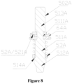
- closed in the application means that the electric valve is in a first valve closed state shown in Figure 3 , or Figure 8 , that is, the state that the valve needle component just closes the valve port after the valve needle component moves in a valve closing direction from a valve opened state.
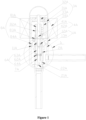
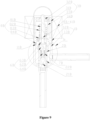
- Figure 1 is a schematic sectional view showing an electric valve according to a first embodiment of the present application, in which the valve is in a fully valve opened state.
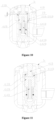
- Figure 2 is a partially enlarged view of a portion I1 in Figure 1 .
- Figure 3 is a partially enlarged view of the portion I1 in a case that the electric valve in Figure 1 is in a first valve closed state.
- Figure 4 is a partially enlarged view of the portion I1 in a case that the electric valve in Figure 1 is in a second valve closed state.
- Figure 5 is a partially enlarged view of the portion I1 in a case that the electric valve in Figure 1 is in a third valve closed state.
- valve core sleeve 2A and the lower valve body 13A are two separate components which are fixed to each other by welding. It is conceivable that the valve core sleeve 2A may be integrated with the lower valve body 13A, that is, the two are processed into one part.
- the valve core sleeve 2A is provided with a valve port 21A, the valve port 21A is substantially arranged in the valve chamber 11A, a lower end portion of the valve core sleeve 2A extends out of the valve chamber 11A and is connected with a second connecting tube, that is, in the present embodiment, the valve core sleeve 2A is partially arranged in the valve chamber 11A.
- the valve needle component 5A is suspendingly connected with the movable connecting component 6A, and the valve needle component 5A is able to be driven by the movable connecting component 6A to axially move with respect to the valve core sleeve 2A.
- the elastic member 7A is sleeved on an outer periphery portion of the valve needle component 5A, one end of the elastic member 7A abuts against the movable connecting component 6A, and the other end abuts against the valve needle components 5A.
- the valve core sleeve 2A includes a first guide inner wall
- the movable connecting component 6A includes a first guide outer wall in sliding clearance fit with the first guide inner wall
- the movable connecting component 6A further includes a second guide inner wall
- the valve needle component 5A includes a second guide outer wall in sliding clearance fit with the second guide inner wall. It is defined that, the first guide inner wall and the first guide outer wall form a first group of guide mechanisms, and the second guide inner wall and the second guide outer wall form a second group of guide mechanisms.
- valve core sleeve 2A is in guiding fit with the movable connecting component 6A through the first guide inner wall and the first guide outer wall, that is, the movable connecting component 6A is guided by the first guide inner wall 201A of the valve core sleeve 2A.
- the movable connecting component 6A includes a second guide inner wall 602A. An end of the valve needle component 5A extends into the movable connecting component 6A.
- the valve needle component 5A has a second guide outer wall 502A in sliding clearance fit with the second guide inner wall 602A. In this way, the movable connecting component 6A is in guiding fit with the valve needle component 5A through the second guide inner wall 602A and the second guide outer wall 502A, that is, the valve needle component 5A is guided by the second guide inner wall 602A of the movable connecting component 6A.
- the valve core sleeve 2A guides the movable connecting component 6A by the cooperation between the first guide inner wall 201A and the first guide outer wall 601A, and the movable connecting component 6A guides the valve needle component 5A by the cooperation between the second guide inner wall 602A and the second guide outer wall 502A.
- the valve needle component 5A is indirectly guided by the valve core sleeve 2A by the arrangement of the two groups of guide mechanisms, so that the valve needle component is more accurately aligned with the valve port, and the valve closing reliability is improved.
- the electric valve of the present embodiment further includes the elastic member 7A, and the elastic member 7A is sleeved outside the valve needle component 5A, one end of the elastic member 7A abuts against the movable connecting component 6A, and the other end abuts against the valve needle component 5A.
- the frictional force is only generated by the gravity of the movable connecting component 6A itself, and a degree of the abrasion is extremely small.
- the elastic member 7A does not generate the elastic force for pushing the valve needle component 5A toward the valve port 21A.
- the second annular portion 641A serves as the second radial protrusion in the present embodiment, and the upper end surface portion 6411A of the second annular portion is configured to abut against a lower clamping member described hereinafter.
- An accommodating groove is formed between the lower end face portion 6412A and a part of an inner side wall, located below second annular portion 641A, of the connecting body 62A, and one end of the elastic member 7A is located in the accommodating groove and abuts against the lower end face portion 6412A.
- valve core sleeve 2A is provided with the first diameter-expanded portion 23A and the second diameter-expanded portion 24A
- two end portions of a connecting body 62B are respectively provided with the first diameter-reduced portion 625A and the second diameter-reduced portion 626A for respectively avoiding the welding positions of the welding of an upper member 63B and a lower member 64B from adversely affecting on the guide function of the first group of guide mechanisms and the second group of guide mechanisms.
- a lower end surface of the lower clamping member is able to abut against an upper end surface of the lower member 64A.
- the function of the lower clamping member 52A is similar to allowing a radial protruding ring with a notch to be formed at the periphery portion of the valve needle 51A.
- the lower clamping member abuts against the second radial protrusion 641A to enable the movable connecting component 6A to suspendingly support the valve needle component 5A.
- the electric valve is in the valve opened state in which the valve needle 51A is separated from the valve port 21A.
- the large-diameter ring portion 421A (the first radial protrusion) of the upper clamping member 42A of the transmission component 4A abuts against the first annular portion 631A of the upper member 63A of the movable connecting component 6A, such that the transmission component 4A suspendingly supports the movable connecting component 6A.
- the radial predetermined displacement amount t1 is provided between the lower end surface portion of the large-diameter ring portion 421A and the first annular portion 622A (the stop portion) of the connection body 62A.
- the elastic member 7A is arranged outside the valve needle component 5A, one end of the elastic member abuts against the movable connecting component, and the other end of the elastic member abuts against the valve needle component 5A. Then, at the very moment when the electric valve is opened (that is, in the process of the valve changing from the second valve closed state to the first valve closed state), the spring force of the elastic member 7A can overcome the aforementioned frictional force, which facilitates valve opening and improves the valve opening reliability.
- the valve core sleeve 2A and the connecting body 62A may be made of two different materials respectively, for example, one is made of brass material, and the other is made of stainless steel material.
- the connecting body 62A and the valve needle 51A may be made of two different materials respectively, for example, one is made of brass material, and the other is made of stainless steel material.
- the wear resistance can also be achieved by coating on the first guide inner wall 201A and the first guide outer wall 601A and on the second guide inner wall 602A and the second guide outer wall 502A.
- the upper member 63A may be sleeved on the periphery portion of the transmission shaft 41A first, and then the upper clamping member 41A is sleeved on the lower end portion of the transmission shaft 41A and fixed to the lower end portion of the transmission shaft 41A by welding.
- Step A22 respectively press-fitting the upper member 63A and the lower member 64A to the upper opening portion and the lower opening portion of the connecting body 62A to serve as the first assembly, allowing the second guide inner wall 602A of the connecting body 62A to be in sliding clearance fit with the second guide outer wall 502A of the guide portion 513A of the valve needle 51A in the first assembly, and allowing the first radial protrusion of the transmission shaft 41A to suspendingly support the first suspension portion of the movable connecting component 6A, and the second radial protrusion of the movable connecting component 6A to suspendingly support the second suspension portion of the lower clamping member 52A.
- Step A5 sleeving the nut component 8A on the periphery of the transmission shaft 41A and threadedly connecting the nut component 8A with the transmission shaft 41A, fixing the nut component 8A to the lower valve body 13A by welding, and fixing the rotor 31A to the transmission shaft 41A by welding.
- Step A6 fixing the upper valve body 12A to the lower valve body 13A by welding, to complete the manufacture of the electric valve in the present embodiment.
- step A2 is performed before or after step A3 is applicable.
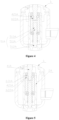
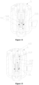
- Figure 9 is a schematic sectional view showing an electric valve according to a second embodiment of the present application, in which the valve is in a fully valve opened state
- Figure 10 is a partially enlarged view of a portion I2 in Figure 9
- Figure 11 is a partially enlarged view of the portion I2 in a case that the electric valve in Figure 9 is in the first valve closed state
- Figure 12 is a partially enlarged view of the portion I2 in a case that the electric valve in Figure 9 is in the second valve closed state
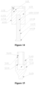
- Figure 13 is a partially enlarged view of the portion I2 in a case that the electric valve in Figure 9 is in the third valve closed state
- Figure 14 is a schematic structural view of the movable connecting component in Figure 9 .
- valve core sleeve 2B may be integrated with the lower valve body 13B, that is, the two are processed into one part.
- the valve core sleeve 2B is provided with a valve port 21B which is substantially arranged in the valve chamber 11B, a lower end portion of the valve core sleeve 2B extends out of the valve chamber 11B and is connected with a second connecting tube, that is, in the present embodiment, the valve core sleeve 2B is partially arranged in the valve chamber 11B.
- the valve core sleeve 2A is a structure which is substantially through in an axial direction.
- the movable connecting component 6B is at least partially arranged in the valve core sleeve 2B and is able to be in sliding clearance fit with the valve core sleeve 2B.
- the movable connecting component 6B is suspendingly connected with the transmission component 4B, and the movable connecting component 6B is able to be driven by the transmission component 4B to axially move with respect to the valve core sleeve 2B.
- An end of the movable connecting component 6B extends into the valve needle component 5B, and the movable connecting component 6B supports the valve needle component 5B.
- the movable connecting component 6B is suspendingly connected with the valve needle component 5B, and the valve needle component 5B is able to be driven by the movable connecting component 6B to axially move with respect to the valve core sleeve 2B.
- the elastic member 7B is sleeved on an outer periphery portion of the valve needle component 5B, one end of the elastic member 7B abuts against the movable connecting component 6B, and the other end abuts against the valve needle components 5B.
- the drive component 3B includes an electromagnetic coil 34B, a rotor 31B, a connecting seat 32B fixedly connected to the rotor 31B, and a stop rod 33B fixedly connected to the connecting seat 32B.
- the electromagnetic coil 3B is fixedly connected to the valve body component 1B by a connecting bracket (not shown).
- the rotor 31B of the drive component 3B is arranged on the outer periphery of the nut component 8B, the rotor 31B is fixedly connected with the transmission component 4B, and coordinates with the electromagnetic coil 34B to drive the transmission component 4B to move in the axial direction of the valve body component 1B.
- the valve needle component 5B and the movable connecting component 6B can correspondingly move to regulate an opening degree of the valve port 21B of the electric valve.
- the valve core sleeve 2B is a structure having a first central through hole and a cylindrical inner wall.
- the movable connecting component 6B is arranged in the first central through hole.
- An inner wall of the first central through hole includes a first guide inner wall 201B.
- An upper end of the movable connecting component 6B extends out of the valve core sleeve 2B, that is, the movable connecting component 6B is partially arranged in the valve core sleeve 2B.
- An outer wall of the movable connecting component 6B includes a first guide outer wall 601B in sliding clearance fit with the first guide inner wall 201B.
- the valve core sleeve 2B is in guiding fit with the movable connecting component 6B through the first guide inner wall 201B and the first guide outer wall 601B, that is, the movable connecting component 6B is guided by the first guide inner wall 201B of the valve core sleeve 2B.
- An outer wall of the movable connecting component 6B further includes a second guide outer wall 602B, and a second guide inner wall 502B in sliding clearance fit with the second guide outer wall 602B is provided on an inner wall the valve needle component 5B.
- the movable connecting component 6B is in guiding fit with the valve needle component 5B through the second guide outer wall 602B and the second guide inner wall 502B.
- the valve needle component 5B is guided by the second guide outer wall 602B of the movable connecting component 6B.
- the electric valve of the present embodiment further includes the elastic member 7B, and the elastic member 7B is sleeved outside the valve needle component 5B, one end of the elastic member 7B abuts against the movable connecting component 6B, and the other end abuts against the valve needle component 5B.
- the transmission component 4B includes a first radial protrusion
- the movable connecting component 6B includes a first suspension portion.
- the first radial protrusion suspendingly supports the first suspension portion, and the first radial protrusion is able to abut against or be separated from the first suspension portion, so that the transmission component 4B suspendingly supports the movable connecting component 6B, that is, the transmission component 4B is suspendingly connected with the movable connecting component 6B.
- the movable connecting component 6B further includes a second radial protrusion
- the valve needle component 5B includes a second suspension portion.
- the second radial protrusion suspendingly supports the second suspension portion, and the second radial protrusion is able to abut against or be separated from the second suspension portion, so that the movable connecting component 6B suspendingly supports the valve needle component 5B, that is, the movable connecting component 6B is suspendingly connected with the valve needle component 5B.
- the movable connecting component 6B includes a stop portion arranged below the first radial protrusion, and when the transmission component 4B moves in the valve closing direction, the first radial protrusion is able to abut against the stop portion.
- the transmission component 4B when the transmission component 4B moves to a position where the first radial protrusion abuts against the first suspension portion and the second radial protrusion abuts against the second suspension portion, the transmission component 4B can drive the movable connecting component 6B to move upward in the axial direction, and the movable connecting component 6B can drive the valve needle component 5B to move upward in the axial direction.
- the elastic member 7B does not generate an elastic force for pushing the valve needle component 5B toward the valve port 21A; and during a time period from when the valve needle component 5B closes the valve port 21B to when the transmission component 4B moves in the valve closing direction by a displacement amount greater than the predetermined displacement amount t2, that is, after the transmission component 4B moves in the valve closing direction to a position where the first radial protrusion abuts against the stop portion, the transmission component 4B pushes the movable connecting component 6B to move in the valve closing direction, and the elastic member 7B pushes the valve needle component 5B toward the valve port 21B.
- the movable connecting component 6B moves downward with respect to the valve core sleeve 2B, the movable connecting component 6B is in guiding fit with the valve core sleeve 2B through the first guide inner wall 201B and the first guide outer wall 601B, abrasion occurs between the first guide inner wall 201B and the first guide outer wall 601B, and a frictional force is generated therebetween.
- the movable connecting component 6B includes a connecting body 62B, and an upper end portion of the connecting body 62B has an upper opening portion 67B, and the bottom 671B of the upper opening portion 67B forms the stop portion in the present embodiment.
- a lower end portion of the connecting body 62B further has a blind hole-like lower inserting hole 68B, the connecting body 62B has a cylindrical outer wall and includes the first guide outer wall 601B which can be in sliding clearance fit with the first guide inner wall 201B of the valve core sleeve 2B.
- the movable connecting component 6B further includes an upper member 63B fixed to the upper opening portion 67B and a substantially rod-shaped lower member 64B of which one end is inserted into the lower inserting hole 68B and fixedly connected to the connecting body 68B.
- the upper member 63B is specifically a first annular member having an axial through hole, and the upper member 63B is sleeved on a periphery of the transmission component 4B and is fixed to the upper opening portion of the connecting body 62B by welding.
- the upper member 63B is fixedly connected to the connecting body 62B to form an accommodating hole 61B.
- the upper member 63B includes a first annular portion 631B having a through hole, which serves as the first suspension portion of the present embodiment.
- a first small-diameter portion 20B is provided on an inner wall of the valve core sleeve 2B, the first small-diameter portion 20B includes the first guide inner wall 201B, and a first diameter-expanded portion 23B with a diameter greater than that of the first small-diameter portion 20B is provided above the first small-diameter portion 20B; or, the outer wall of the connecting body 62B includes a first large-diameter portion 624B and a first diameter-reduced portion 625B arranged above the first large-diameter portion 624B, the first large-diameter portion 624B includes the first guide outer wall 601B,
- the upper end of the lower member 64B is fixedly connected to the connecting body 62B by press-fitting, or welding, or the combination of press-fitting and welding.
- the lower member 64B includes an extending portion 641B inserting into the lower inserting hole 68B, a second radial protrusion 642B radially extending along a lower end portion of the lower member 64B, and a base portion 643B connecting with the extending portion 641B and the first radial protrusion 642B.
- the second guide outer wall 602B of the present embodiment is arranged on an outer wall of the base portion 643B.
- the "connection" herein includes that the lower member is a split structure and the separate members of the split structure are fixedly connected by welding, and also includes that the lower member is an integral structure.
- a predetermined radial displacement amount may be provided between the transmission shaft 41B and the connecting body 62B, and between an upper clamping member 42B and the connecting body 62B respectively, so that center alignment of the transmission shaft 41B can be performed self-adaptively.
- the main body portion 511B and the lower clamping member 52B together form a first stepped portion 514B.
- the first stepped portion 514B is provided with a gasket 53B.
- the lower clamping member 52B is a structure which is substantially through in the axial direction.
- the lower clamping member 52B is sleeved on a periphery of the base portion 643B of the lower member 64B, and the elastic member 7B is sleeved on a periphery portion of the lower clamping member 52B.
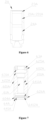
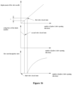
- FIG. 16 is a second schematic view showing operational characteristics of the electric valve according to the present application, which shows a relationship between the number of pulses of the electromagnetic coil and the frictional forces of the first group of guide mechanisms and the second group of guide mechanisms.
- the drive component 3B of the electric valve drives the transmission component 4B to move in the valve closing direction until the flow regulating portion 512B of the valve needle 51B comes into contact with the valve port 21B to close the valve port 21B, that is, until reaching the first valve closed state shown in Figure 12 .
- the second valve closed state is a process in which the displacement amount of the transmission shaft 41B moving in the valve closing direction from the first closed valve state is less than or equal to the predetermined displacement amount t2.
- Figure 12 is a view showing the state that the displacement amount of the transmission component 4B is equal to the predetermined displacement amount t2, which is a very moment when the first radial protrusion 411B of the transmission shaft 41B just comes into contact with the stop portion 671B of the connecting body 62B, but does not apply a force to the stop portion 671B.
- the drive component 3B further drives the transmission shaft 41B to move axially in the valve closing direction. Since the first radial protrusion 411B of the transmission shaft 41B abuts against the stop portion 671B of the connecting body 62B, the movable connecting component 6B is pressed by the transmission shaft 41B to move downward during the downward movement of the transmission shaft 41B, the movable connecting component 6B moves axially with respect to the valve core sleeve 2B, and the movable connecting component 6B moves axially with respect to the valve needle component 5B, such that a frictional force is generated between the first guide inner wall 201B and the first guide outer wall 601B and also between the second guide inner wall 601B and the second guide inner wall 502B.
- the elastic member 7B is arranged outside the movable connecting component 6B, one end of the elastic member abuts against the movable connecting component 6B, and the other end of the elastic member abuts against the valve needle component 5B. Then, at the very moment when the electric valve is opened (that is, in the process of the valve changing from the second valve closed state to the first valve closed state), the spring force of the elastic member 7B can overcome the aforementioned frictional force, which facilitates valve opening and improves the valve opening reliability.
- the valve needle 51B rotates together with the transmission shaft 41B with respect to the valve port 21B, and there is abrasion at a portion where the valve port 21B is in contact with the valve needle 51B.
- the frictional force between the valve needle 51B and the transmission component 4B is smaller than the frictional force between the valve needle 51B and the valve port 21B, the valve needle 51B does not rotate together with the transmission component 4B, then there is very little abrasion at the portion where the valve port 21B is in contact with the valve needle 51B. Therefore, in order to reduce the frictional force between the valve needle 51B and the transmission component 4B, the gasket 53B described hereinbefore is provided.
- the first guide inner wall 201B and the first guide outer wall 601B, the second guide inner wall 502B and the second guide outer wall 602B are provided, the valve closing reliability is improved, and the operation reliability of the valve needle component is improved by the two groups of guide mechanisms.
- the elastic member 7B is arranged outside the movable connecting component 6B, one end of the elastic member abuts against the movable connecting component, and the other end of the elastic member abuts against the valve needle component 5B. Then, at the very moment when the electric valve is opened (that is, in the process of the valve changing from the second valve closed state to the first valve closed state), the spring force of the elastic member 7B can overcome the aforementioned frictional force, which facilitates valve opening and improves the valve opening reliability.
- the elastic member 7B is arranged below the first group of guide mechanisms and the second group of guide mechanisms, which is more helpful to overcome the frictional force between the first guide inner wall 201B and the first guide outer wall 601B and between the second guide inner wall 502B and the second guide outer wall 602B.
- the transmission component suspendingly supports the movable connecting component and the movable connecting component suspendingly supports the valve needle component, at the very moment when the valve needle 51B closes the valve port 21B and the very moment when the valve needle 51B is separated from the valve port 21B, and during the process of the second valve closed state, the frictional force between the valve needle 51B and the valve port 21B is caused only by the self-weights of the valve needle component 5B and the movable connecting component 6B. In this way, even if the electric valve is repeatedly operated, there is very little abrasion at the portion where the valve needle 51B is in contact with the valve port 21B, thereby reducing internal leakage of the electric valve in the valve closed state.
- valve needle 51B is separated from the valve port 21B.
- the frictional force between the valve needle 51B and the valve port 21B is caused only by the self-weights of the valve needle component 5B and the movable connecting component 6B, and even if the electric valve is repeatedly operated, there is very little abrasion at the portion where the valve needle 51B is in contact with the valve port 21B, which further improves the valve closing reliability.
- the valve core sleeve 2B and the connecting body 62B may be made of two different materials respectively, for example, one is made of brass material, and the other is made of stainless steel material.
- the lower member 64B and the lower clamping member 52B may be made of two different materials respectively, for example, one is made of brass material, and the other is made of stainless steel material.
- the wear resistance can also be achieved by coating on the first guide inner wall 201B and the first guide outer wall 601B and on the second guide outer wall 602B and the second guide inner wall 502B.
- a method for manufacturing the electric valve of the present embodiment is described hereinafter, which includes the following steps:
- the transmission component 4B may adopt the split structure shown in the first embodiment, and will not be repeated herein.
- the movable connecting component 6B in the present embodiment may also be entirely arranged in the valve core sleeve 2B, that is, the movable connecting component 6B does not extend out of the valve core sleeve 2B. It should be understood that, the lower end portion of the valve needle component 5B may extend out of the valve core sleeve 2A as well, as long as the object of the present application can be achieved.
- the valve port of the electric valve is arranged at the valve core sleeve.
- the valve core sleeve is a cylindrical structure having a core chamber
- the valve core sleeve is fixedly connected to the valve body component
- a peripheral wall of the valve core sleeve is further provided with communication ports 22A/22B to allow an inner chamber of the valve core sleeve to be in communication with an outer space of the valve core sleeve, so that when the valve port is in the valve opened state, a fluid inlet and a fluid outlet of the electric valve can be in communication with each other through the valve port and the communication ports.
- the elastic member 7A/7B in each of the above embodiments may specifically be a compression spring.
- valve core sleeve may be fixed to the nut component, to improve the coaxiality between the nut component and the valve core sleeve, thereby controlling the coaxiality between the transmission component and the valve core sleeve.
- valve port may be directly arranged at the lower valve body or another component may be provided and the valve port may be arranged thereon, and a separate valve core sleeve may be arranged inside the valve body component for guiding the movable connecting component and the valve needle component.
- valve core sleeve in each of the embodiments may not be directly fixed to the valve body component, instead, the valve core sleeve may be fixed another component, and then the above component is fixedly connected to the valve body component.
- the method for manufacturing the electric valve according to the present application is exemplified hereinbefore, so that the technical solution of the present application can be understood. It should be understood that, the above steps are numbered only for clearly illustrating the assembly steps of the electric valve, and the order of the numbers does not represent the order of the steps. As long as the assembly of the electric valve can be realized, the order of the steps can be flexibly adjusted according to needs.
Landscapes
- Engineering & Computer Science (AREA)
- General Engineering & Computer Science (AREA)
- Mechanical Engineering (AREA)
- Physics & Mathematics (AREA)
- Optics & Photonics (AREA)
- Thermal Sciences (AREA)
- Electrically Driven Valve-Operating Means (AREA)
- Magnetically Actuated Valves (AREA)
Claims (14)
- Elektrisches Ventil, aufweisend:ein Ventilkörperbauteil (1A) mit einer Ventilkernhülse (2A), wobei die Ventilkernhülse (2A) eine erste Führungsinnenwand (201A) aufweist;eine Antriebskomponente (3A), die eine elektromagnetische Spule (34A) und einen Rotor (31A) aufweist;ein Übertragungsbauteil (4A), das eine Übertragungswelle (41A) aufweist, wobei die Übertragungswelle (41A) mit der Antriebskomponente (3A) fest verbunden ist;ein bewegbares Verbindungsbauteil (6A), das mit dem Übertragungsbauteil (4A) hängend verbunden ist, wobei das bewegbare Verbindungsbauteil (6A) dafür ausgelegt ist, durch das Übertragungsbauteil (4A) angetrieben zu werden, um sich axial in Bezug auf die Ventilkernhülse (2A) zu bewegen; wobei das bewegbare Verbindungsbauteil (6A) einen Verbindungskörper (62A) aufweist, der Verbindungskörper (62A) eine erste Führungsaußenwand (601A) aufweist, die erste Führungsaußenwand (601A) sich in einer Gleitsitzpassung mit der ersten Führungsinnenwand (201A) befindet, der Verbindungskörper (62A) einen unteren Öffnungsabschnitt (604A) und eine Aufnahmeöffnung (61A) in Verbindung mit dem unteren Öffnungsabschnitt (604A) aufweist, und eine Öffnungswand der Aufnahmeöffnung (61A) eine zweite Führungsinnenwand (602A) aufweist;ein Ventilnadelbauteil (5A), das mit dem bewegbaren Verbindungsbauteil (6A) hängend verbunden ist, wobei das Ventilnadelbauteil (5A) dafür ausgelegt ist, durch das bewegbare Verbindungsbauteil (6A) angetrieben zu werden, um sich axial in Bezug auf die Ventilkernhülse (2A) zu bewegen; das Ventilnadelbauteil (5A) eine Ventilnadel (51A) aufweist, die Ventilnadel (51A) eine zweite Führungsaußenwand (502A) aufweist und die zweite Führungsaußenwand (502A) sich in einer Gleitsitzpassung mit der zweiten Führungsinnenwand (602A) befindet; undein elastisches Element (7A), wobei ein Ende des elastischen Elements (7A) sich am bewegbaren Verbindungsbauteil (6A) abstützt, und ein anderes Ende des elastischen Elements (7A) sich an der Ventilnadel (51A) abstützt,wobei das Übertragungsbauteil (4A) einen ersten radialen Vorsprung aufweist, das bewegbare Verbindungsbauteil (6A) einen ersten Hängeabschnitt und einen zweiten radialen Vorsprung aufweist, und das Ventilnadelbauteil (5A) einen zweiten Hängeabschnitt aufweist; wobei der erste radiale Vorsprung dafür ausgelegt ist, sich am ersten Hängeabschnitt abzustützen oder von diesem getrennt zu sein, und der zweite radiale Vorsprung dafür ausgelegt ist, sich am zweiten Hängeabschnitt abzustützen oder von diesem getrennt zu sein;dadurch gekennzeichnet, dass der Verbindungskörper (62A) einen Anschlagabschnitt aufweist, der unterhalb des ersten radialen Vorsprungs angeordnet ist, und, nachdem sich das Übertragungsbauteil (4A) in einer Ventilschließrichtung zu einer Position bewegt hat, an der sich der erste radiale Vorsprung am Anschlagabschnitt abstützt, das Übertragungsbauteil (4A) dafür ausgelegt ist, das bewegbare Verbindungsbauteil (6A) zu verschieben, um sich in der Ventilschließrichtung zu bewegen, und das elastische Element (7A) dafür ausgelegt ist, die Ventilnadel (51A) zu einer Ventilöffnung (21A) hin zu verschieben.
- Elektrisches Ventil nach Anspruch 1, wobeider Verbindungskörper (62A) darüber hinaus einen oberen Öffnungsabschnitt (603A) aufweist, das bewegbare Verbindungsbauteil (6A) darüber hinaus ein oberes Element (63A), das am oberen Öffnungsabschnitt (603A) angeordnet ist, und ein unteres Element (64A) aufweist, das am unteren Öffnungsabschnitt angeordnet ist; das obere Element (63A) einen ersten ringförmigen Abschnitt (631A) mit einer Durchgangsöffnung aufweist und der erste ringförmige Abschnitt (631A) als der erste Hängeabschnitt dient; das untere Element (64A) ein Basiselement mit einer Durchgangsöffnung aufweist, das Basiselement an einem Umfang der Ventilnadel (51A) angeordnet ist, eine Innenwand des Basiselements einen zweiten ringförmigen Abschnitt (641A) aufweist, der zweite ringförmige Abschnitt (641A) als der zweite radiale Vorsprung dient, das Übertragungsbauteil (4A) darüber hinaus ein oberes Klemmelement (42A) aufweist, das an einem unteren Endabschnitt der Übertragungswelle (41A) angeordnet ist, das obere Klemmelement (42A) einen ringförmigen Abschnitt (624A) mit großem Durchmesser aufweist, der sich zwischen dem oberen Element (63A) und dem Anschlagabschnitt befindet, und der ringförmige Abschnitt mit großem Durchmesser als der erste radiale Vorsprung dient;und eine Innenwand des Verbindungskörpers (62A) einen ersten ringförmigen Vorsprung entgegengesetzt zum ersten radialen Vorsprung aufweist, und der erste ringförmige Vorsprung als der Anschlagabschnitt dient.
- Elektrisches Ventil nach Anspruch 1, wobei
das Ventilnadelbauteil (5A) darüber hinaus ein unteres Klemmelement (52A) aufweist, die Ventilnadel (51A) einen Hauptkörperabschnitt (511A), einen Strömungsregulierungsabschnitt (512A), der sich unterhalb des Hauptkörperabschnitts (511A) befindet, und einen Führungsabschnitt aufweist, der sich oberhalb des Hauptkörperabschnitts (511A) befindet, wobei der Führungsabschnitt in der Aufnahmeöffnung (61A) und die zweite Führungsaußenwand (502A) an einer Außenwand des Führungsabschnitts (513A) angeordnet ist; das untere Klemmelement (52A) an einem Umfang des Hauptkörperabschnitts (511A) angeordnet ist; ein unterer Endflächenabschnitt des unteren Klemmelements (52A) als der zweite Hängeabschnitt dient; und ein Ende des elastischen Elements (7A) sich am bewegbaren Verbindungsbauteil (6A) abstützt, und ein anderes Ende des elastischen Elements (7A) sich am Hauptkörperabschnitt (511A) abstützt. - Elektrisches Ventil nach Anspruch 2, wobeieine Innenwand der Ventilkernhülse (2A) einen ersten Abschnitt (20A) mit kleinem Durchmesser und einen ersten Abschnitt (23A) mit erweitertem Durchmesser aufweist, der oberhalb des ersten Abschnitts (20A) mit kleinem Durchmesser angeordnet ist, und die erste Führungsinnenwand (201A) am ersten Abschnitt (20A) mit kleinem Durchmesser angeordnet ist;und der obere Öffnungsabschnitt (603A) des Verbindungskörpers (62A) am oberen Element (63A) durch Schweißen befestigt ist und/oder eine Außenwand des Verbindungskörpers (62A) einen ersten Abschnitt (624A) mit großem Durchmesser und einen ersten Abschnitt (625A) mit verringertem Durchmesser aufweist, der oberhalb des ersten Abschnitts mit großem Durchmesser angeordnet ist, die erste Führungsaußenwand (601A) am ersten Abschnitt (624A) mit großem Durchmesser angeordnet und der erste Abschnitt (625A) mit verringertem Durchmesser am oberen Element (63A) durch Schweißen befestigt ist.
- Elektrisches Ventil nach Anspruch 2, wobeieine Innenwand der Ventilkernhülse (2A) einen ersten Abschnitt (20A) mit kleinem Durchmesser und einen zweiten Abschnitt (24A) mit erweitertem Durchmesser aufweist, der unterhalb des ersten Abschnitts (20A) mit kleinem Durchmesser angeordnet ist, und die erste Führungsinnenwand (201A) am ersten Abschnitt (20A) mit kleinem Durchmesser angeordnet ist;und der untere Öffnungsabschnitt des Verbindungskörpers (62A) am unteren Element (64A) durch Schweißen befestigt ist und/oder eine Außenwand des Verbindungskörpers (62A) einen ersten Abschnitt (624A) mit großem Durchmesser und einen zweiten Abschnitt (625A) mit verringertem Durchmesser aufweist, der unterhalb des ersten Abschnitts (624A) mit großem Durchmesser angeordnet ist, die erste Führungsaußenwand (601A) am ersten Abschnitt (624A) mit großem Durchmesser angeordnet ist und der zweite Abschnitt (625A) mit verringertem Durchmesser am unteren Element (64A) durch Schweißen befestigt ist.
- Verfahren zur Herstellung des elektrischen Ventils nach Anspruch 1, umfassend:A1, Bereitstellen eines oberen Ventilkörpers (12A), eines unteren Ventilkörpers (13A) und einer Ventilkernhülse (2A) eines Ventilkörperbauteils (1A), Bereitstellen eines Rotors (31A), Bereitstellen eines Verbindungskörpers (62A), eines oberen Elements (63A) und eines unteren Elements (64A) eines bewegbaren Verbindungsbauteils (6A), Bereitstellen einer Ventilnadel (51A) und eines unteren Klemmelements (52A) eines Ventilnadelbauteils (5A), Bereitstellen eines Übertragungsbauteils (4A) und Bereitstellen eines Mutterbauteils (8A);A2, Anordnen eines elastischen Elements (7A), des unteren Elements (64A) und des unteren Klemmelements (52A) an einem Umfangsabschnitt der Ventilnadel (51A), Ermöglichen, dass ein Ende des elastischen Elements (7A) sich am unteren Element (64A) und ein anderes Ende an der Ventilnadel (51A) abstützt; Anordnen des oberen Elements (63A) an einem Umfangsabschnitt einer Übertragungswelle (41A); Aufschieben des Verbindungskörpers (62A) auf einen Umfangsabschnitt der Ventilnadel (51A), Ermöglichen, dass der Verbindungskörper (62A) sich in einer Gleitsitzpassung mit der Ventilnadel (51A) befindet, durch eine zweite Führungsinnenwand (602A) und eine zweite Führungsaußenwand (502A), und festes Verbinden des oberen Elements (63A) und des unteren Elements (64A) mit einem oberen Öffnungsabschnitt (603A) bzw. einem unteren Öffnungsabschnitt des Verbindungskörpers (62A);A3, festes Verbinden des unteren Ventilkörpers (13A) mit der Ventilkernhülse (2A);A4, Ermöglichen, dass sich die Ventilkernhülse (2A) in einer Gleitsitzpassung mit dem Verbindungskörper (62A) befindet, durch eine erste Führungsinnenwand (201A) und eine erste Führungsaußenwand (601A);A5, Herstellen einer Gewindeverbindung zwischen dem Mutterbauteil (8A) und der Übertragungswelle (41A), festes Verbinden des Mutterbauteils (8A) mit dem unteren Ventilkörper (13A), und festes Verbinden des Rotors mit der Übertragungswelle (41A); undA6, Befestigen des oberen Ventilkörpers (12A) des Ventilkörperbauteils (1A) am unteren Ventilkörper (13A) durch Schweißen.
- Verfahren nach Anspruch 6 zur Herstellung des elektrischen Ventils, wobei
Schritt A2 nach Schritt A3 durchgeführt wird. - Elektrisches Ventil, aufweisend:ein Ventilkörperbauteil (1B) mit einer Ventilkernhülse (2B), wobei die Ventilkernhülse (2B) eine erste Führungsinnenwand (201B) aufweist;ein Antriebskomponente (3B) mit einer elektromagnetischen Spule (34B) und einem Rotor;ein Übertragungsbauteil (4B) mit einer Übertragungswelle (41B), wobei die Übertragungswelle (41B) mit der Antriebskomponente (3B) fest verbunden ist;ein bewegbares Verbindungsbauteil (6B), das mit dem Übertragungsbauteil (4B) hängend verbunden ist, wobei das bewegbare Verbindungsbauteil (6B) dafür ausgelegt ist, durch das Übertragungsbauteil (4B) angetrieben zu werden, um sich axial in Bezug auf die Ventilkernhülse (2B) zu bewegen; wobei das bewegbare Verbindungsbauteil (6B) einen Verbindungskörper (62B) und ein unteres Element (64B) aufweist, das mit dem Verbindungskörper (62B) fest verbunden ist, der Verbindungskörper (62B) eine erste Führungsaußenwand aufweist, die erste Führungsaußenwand sich in einer Gleitsitzpassung mit der ersten Führungsinnenwand (201B) befindet, und das untere Element (64B) eine zweite Führungsaußenwand (602B) aufweist;ein Ventilnadelbauteil (5B), das mit dem bewegbaren Verbindungsbauteil (6B) hängend verbunden ist, wobei das Ventilnadelbauteil (5B) dafür ausgelegt ist, durch das bewegbare Verbindungsbauteil (6B) angetrieben zu werden, um sich axial in Bezug auf die Ventilkernhülse (2B) zu bewegen; das Ventilnadelbauteil (5B) eine Ventilnadel (51B) und ein unteres Klemmelement (52B) aufweist, die Ventilnadel (51B) mit dem unteren Klemmelement (52B) fest verbunden ist, das untere Klemmelement (52B) eine zweite Führungsinnenwand (502B) aufweist und die zweite Führungsinnenwand (502B) sich in einer Gleitsitzpassung mit der zweiten Führungsaußenwand (602B) befindet; undein elastisches Element (7B), wobei ein Ende des elastischen Elements (7B) sich am Verbindungskörper (62B) und ein anderes Ende des elastischen Elements (7B) sich an der Ventilnadel (51B) abstützt.
- Elektrisches Ventil nach Anspruch 8, wobei das Übertragungsbauteil (4B) einen ersten radialen Vorsprung (411B) aufweist, der Verbindungskörper (62B) einen ersten Hängeabschnitt (631B) aufweist, das untere Element (64B) einen zweiten radialen Vorsprung aufweist, und das untere Klemmelement (52B) einen zweiten Hängeabschnitt aufweist; der erste radiale Vorsprung (411B) dafür ausgelegt ist, sich am ersten Hängeabschnitt (631B) abzustützen oder von diesem getrennt zu sein, und der zweite radiale Vorsprung dafür ausgelegt ist, sich am zweiten Hängeabschnitt abzustützen oder von diesem getrennt zu sein; und der Verbindungskörper (62B) einen Anschlagabschnitt (671B) aufweist, der unterhalb des ersten radialen Vorsprungs (411B) angeordnet ist, und, nachdem sich das Übertragungsbauteil (4B) in einer Ventilschließrichtung zu einer Position bewegt hat, an der sich der erste radiale Vorsprung (411B) am Anschlagabschnitt (671B) abstützt, das Übertragungsbauteil (4B) dafür ausgelegt ist, das bewegbare Verbindungsbauteil (6B) zu verschieben, um sich in der Ventilschließrichtung zu bewegen, und das elastische Element (7B) dafür ausgelegt ist, die Ventilnadel (51B) zu einer Ventilöffnung (21B) hin zu verschieben.
- Elektrisches Ventil nach Anspruch 9, wobei der erste radiale Vorsprung (411B) an einem unteren Endabschnitt der Übertragungswelle (41B) angeordnet ist, der Verbindungskörper (62B) einen oberen Öffnungsabschnitt (603B) aufweist, eine Unterseite des oberen Öffnungsabschnitts (603B) als der Anschlagabschnitt (671B) dient, der Verbindungskörper (62B) darüber hinaus eine untere Einführöffnung (68B) aufweist, das untere Element (64B) einen Erstreckungsabschnitt (641B) aufweist, der sich in die untere Einführöffnung (68B) erstreckt, ein zweiter radialer Vorsprung sich in einer radialen Richtung des unteren Endabschnitts des unteren Elements (64B) erstreckt, und ein Basisabschnitt eine Verbindung mit dem Erstreckungsabschnitt (641B) und dem zweiten radialen Vorsprung hat, und die zweite Führungsaußenwand (502B) an einer Außenwand des Basisabschnitts angeordnet ist; und das bewegbare Verbindungsbauteil (6B) darüber hinaus ein oberes Element (63B) aufweist, das am oberen Öffnungsabschnitt (603B) angeordnet ist, das obere Element (63B) einen ersten ringförmigen Abschnitt (631B) mit einer Durchgangsöffnung aufweist und der erste ringförmige Abschnitt (631B) als der erste Hängeabschnitt (631B) dient.
- Elektrisches Ventil nach Anspruch 9, wobei die Ventilnadel (51B) einen Hauptkörperabschnitt (511B) und einen Strömungsregulierungsabschnitt (512B) aufweist, der sich unterhalb des Hauptkörperabschnitts (511B) befindet, das untere Klemmelement (52B) eine Struktur darstellt, die in der axialen Richtung im Wesentlichen durchgängig ist, das untere Klemmelement (52B) auf einen Umfangsabschnitt des unteren Elements (64B) aufgeschoben ist, das elastische Element (7B) an einem Umfangsabschnitt des unteren Klemmelements (52B) angeordnet ist, ein Ende des elastischen Elements (7B) sich am Verbindungskörper (62B) und ein anderes Ende des elastischen Elements (7B) sich am Hauptkörperabschnitt (511B) abstützt.
- Elektrisches Ventil nach Anspruch 10, wobei eine Innenwand der Ventilkernhülse (2B) einen ersten Abschnitt (20B) mit kleinem Durchmesser und einen ersten Abschnitt mit erweitertem Durchmesser aufweist, der oberhalb des ersten Abschnitts (20B) mit kleinem Durchmesser angeordnet ist, und die erste Führungsinnenwand (201B) am ersten Abschnitt (20B) mit kleinem Durchmesser angeordnet ist; und der obere Öffnungsabschnitt (603B) des Verbindungskörpers (62B) am oberen Element (63B) durch Schweißen befestigt ist und/oder eine Außenwand des Verbindungskörpers (62B) einen ersten Abschnitt (624B) mit großem Durchmesser (624B) und einen ersten Abschnitt (625B) mit verringertem Durchmesser aufweist, der oberhalb des ersten Abschnitts (624B) mit großem Durchmesser (624B) angeordnet ist, die erste Führungsaußenwand am ersten Abschnitt (624B) mit großem Durchmesser angeordnet ist und der erste Abschnitt (625B) mit verringertem Durchmesser am oberen Element (63B) durch Schweißen befestigt ist.
- Verfahren zur Herstellung des elektrischen Ventils nach Anspruch 8, umfassend:A1, Bereitstellen eines oberen Ventilkörpers (12B), eines unteren Ventilkörpers (13B) und einer Ventilkernhülse (2B) eines Ventilkörperbauteils (1B), Bereitstellen des Rotors, Bereitstellen eines Verbindungskörpers (62B), eines oberen Elements (63B) und eines unteren Elements (64B) eines bewegbaren Verbindungsbauteils (6B), Bereitstellen einer Ventilnadel (51B) und eines unteren Klemmelements (52B) eines Ventilnadelbauteils (5B), Bereitstellen eines Übertragungsbauteils (4B) und Bereitstellen eines Mutterbauteils (8B);A2, Aufschieben des unteren Klemmelements (52B) auf einen Umfang des unteren Elements (64B), Ermöglichen, dass sich das untere Klemmelement (52B) in einer Gleitsitzpassung mit dem unteren Element (64B) befindet, durch eine zweite Führungsinnenwand (602B) und eine zweite Führungsaußenwand (502B), festes Verbinden des unteren Klemmelements (52B) mit der Ventilnadel (51B), Anordnen des elastischen Elements (7B) an einem Umfang des unteren Klemmelements (52B), Einstecken eines oberen Endes des unteren Elements (64B) in eine untere Einführöffnung (68B) des Verbindungskörpers (62B) und festes Verbinden des unteren Elements (64B) mit dem Verbindungskörper (62B), Anordnen des oberen Elements (63B) an einem Umfang der Übertragungswelle (41B) und festes Verbinden des oberen Elements (63B) mit einem oberen Öffnungsabschnitt (603B) des Verbindungskörpers (62B);A3, festes Verbinden des unteren Ventilkörpers (13B) mit der Ventilkernhülse (2B);A4, Ermöglichen, dass sich die Ventilkernhülse (2B) in einer Gleitsitzpassung mit dem Verbindungskörper (62B) befindet, durch eine erste Führungsinnenwand (201B) und eine erste Führungsaußenwand;A5, Herstellen einer Gewindeverbindung zwischen dem Mutterbauteil (8B) und der Übertragungswelle (41B), festes Verbinden des Mutterbauteils (8B) mit dem unteren Ventilkörper (13B), und festes Verbinden des Rotors mit der Übertragungswelle (41B); undA6, Befestigen des oberen Ventilkörpers (12B) des Ventilkörperbauteils (1B) am unteren Ventilkörper (13B) durch Schweißen.
- Verfahren nach Anspruch 13 zur Herstellung des elektrischen Ventils, wobei
Schritt A2 nach Schritt A3 durchgeführt wird.
Applications Claiming Priority (3)
| Application Number | Priority Date | Filing Date | Title |
|---|---|---|---|
| CN201810147921 | 2018-02-13 | ||
| CN201810148020 | 2018-02-13 | ||
| PCT/CN2018/085982 WO2019157782A1 (zh) | 2018-02-13 | 2018-05-08 | 一种电动阀及其制造方法 |
Publications (5)
| Publication Number | Publication Date |
|---|---|
| EP3754237A1 EP3754237A1 (de) | 2020-12-23 |
| EP3754237A4 EP3754237A4 (de) | 2021-11-10 |
| EP3754237B1 true EP3754237B1 (de) | 2023-06-28 |
| EP3754237C0 EP3754237C0 (de) | 2023-06-28 |
| EP3754237B8 EP3754237B8 (de) | 2023-08-30 |
Family
ID=67620180
Family Applications (1)
| Application Number | Title | Priority Date | Filing Date |
|---|---|---|---|
| EP18906699.6A Active EP3754237B8 (de) | 2018-02-13 | 2018-05-08 | Elektrisches ventil und herstellungsverfahren dafür |
Country Status (4)
| Country | Link |
|---|---|
| US (1) | US11193596B2 (de) |
| EP (1) | EP3754237B8 (de) |
| KR (1) | KR102339345B1 (de) |
| WO (1) | WO2019157782A1 (de) |
Families Citing this family (4)
| Publication number | Priority date | Publication date | Assignee | Title |
|---|---|---|---|---|
| EP3940280A4 (de) * | 2019-03-13 | 2023-03-22 | Zhejiang Dunan Artificial Environment Co., Ltd. | Elektronisches expansionsventil und kühlsystem |
| CN210372066U (zh) * | 2019-06-14 | 2020-04-21 | 浙江盾安禾田金属有限公司 | 电子膨胀阀 |
| CN115370756A (zh) * | 2021-05-18 | 2022-11-22 | 浙江三花汽车零部件有限公司 | 电动阀及其装配方法 |
| WO2023066116A1 (zh) * | 2021-10-20 | 2023-04-27 | 浙江盾安人工环境股份有限公司 | 阀针部件及流量调节阀 |
Family Cites Families (13)
| Publication number | Priority date | Publication date | Assignee | Title |
|---|---|---|---|---|
| JPH0968287A (ja) | 1995-08-31 | 1997-03-11 | Tokyo Danreiki Seisakusho:Kk | 電磁弁 |
| JP3091953B2 (ja) * | 1995-10-04 | 2000-09-25 | リンナイ株式会社 | ガス弁装置 |
| JP2003329158A (ja) | 2002-05-15 | 2003-11-19 | Saginomiya Seisakusho Inc | 電動弁 |
| CN100510580C (zh) | 2004-12-15 | 2009-07-08 | 株式会社鹭宫制作所 | 电动式控制阀 |
| JP2008175240A (ja) | 2007-01-16 | 2008-07-31 | Fuji Koki Corp | 電動弁 |
| EP2211077B1 (de) | 2009-01-22 | 2016-10-19 | Fujikoki Corporation | Motorgesteuertes Ventil |
| JP5943549B2 (ja) * | 2011-02-24 | 2016-07-05 | 株式会社不二工機 | 電動弁 |
| WO2013127276A1 (zh) * | 2012-02-28 | 2013-09-06 | 艾默生环境优化技术(苏州)有限公司 | 电子膨胀阀 |
| CN105090534B (zh) * | 2014-04-30 | 2017-05-17 | 浙江三花制冷集团有限公司 | 一种直动式电动阀 |
| JP6231509B2 (ja) * | 2015-02-02 | 2017-11-15 | 株式会社鷺宮製作所 | 絞り装置及び冷凍サイクル |
| CN206159607U (zh) * | 2016-08-31 | 2017-05-10 | 浙江鸿森机械有限公司 | 活塞电磁阀的先导阀芯装置 |
| CN206647571U (zh) * | 2017-04-20 | 2017-11-17 | 浙江中孚流体机械有限公司 | 一种二位四通高压电磁阀 |
| JP7325246B2 (ja) * | 2019-06-28 | 2023-08-14 | 株式会社吉野工業所 | キャップおよびキャップの製造方法 |
-
2018
- 2018-05-08 WO PCT/CN2018/085982 patent/WO2019157782A1/zh not_active Ceased
- 2018-05-08 US US16/967,707 patent/US11193596B2/en active Active
- 2018-05-08 EP EP18906699.6A patent/EP3754237B8/de active Active
- 2018-05-08 KR KR1020207024909A patent/KR102339345B1/ko active Active
Also Published As
| Publication number | Publication date |
|---|---|
| KR20200116141A (ko) | 2020-10-08 |
| EP3754237A4 (de) | 2021-11-10 |
| KR102339345B1 (ko) | 2021-12-16 |
| US20210041028A1 (en) | 2021-02-11 |
| EP3754237C0 (de) | 2023-06-28 |
| US11193596B2 (en) | 2021-12-07 |
| EP3754237A1 (de) | 2020-12-23 |
| WO2019157782A1 (zh) | 2019-08-22 |
| EP3754237B8 (de) | 2023-08-30 |
Similar Documents
| Publication | Publication Date | Title |
|---|---|---|
| EP3754237B1 (de) | Elektrisches ventil und herstellungsverfahren dafür | |
| JP7198351B2 (ja) | 流量制御弁 | |
| CN110291314B (zh) | 一种电子膨胀阀及其组装方法 | |
| EP3273186B1 (de) | Motorbetriebenes ventil | |
| KR102320122B1 (ko) | 전자밸브 | |
| KR102375852B1 (ko) | 전자밸브 | |
| CN113883113B (zh) | 电磁阀 | |
| JP2023503404A (ja) | 電子膨張弁 | |
| EP3620728A1 (de) | Motorbetriebenes ventil | |
| JP7049461B2 (ja) | 電動弁及びその製造方法 | |
| CN110145629B (zh) | 一种电动阀及其制造方法 | |
| EP3929476B1 (de) | Durchflussregelungsventil | |
| CN111379864B (zh) | 一种流量控制阀 | |
| CN110159827B (zh) | 一种电动阀及其制造方法 | |
| CN113775771A (zh) | 一种电动阀 | |
| AU2021411869B2 (en) | Valve, and method for manufacturing said valve | |
| CN112539284B (zh) | 一种流量控制阀 | |
| WO2025067546A1 (zh) | 电子膨胀阀及其加工方法 | |
| CN120231883A (zh) | 一种控制阀 | |
| CN115681602A (zh) | 一种电动阀 | |
| JP2024171419A (ja) | 電動弁 | |
| JP2025043403A (ja) | 電動弁 | |
| JP2007285362A (ja) | バルブ装置 | |
| CN117090943A (zh) | 一种电动阀 |
Legal Events
| Date | Code | Title | Description |
|---|---|---|---|
| STAA | Information on the status of an ep patent application or granted ep patent |
Free format text: STATUS: THE INTERNATIONAL PUBLICATION HAS BEEN MADE |
|
| PUAI | Public reference made under article 153(3) epc to a published international application that has entered the european phase |
Free format text: ORIGINAL CODE: 0009012 |
|
| STAA | Information on the status of an ep patent application or granted ep patent |
Free format text: STATUS: REQUEST FOR EXAMINATION WAS MADE |
|
| 17P | Request for examination filed |
Effective date: 20200807 |
|
| AK | Designated contracting states |
Kind code of ref document: A1 Designated state(s): AL AT BE BG CH CY CZ DE DK EE ES FI FR GB GR HR HU IE IS IT LI LT LU LV MC MK MT NL NO PL PT RO RS SE SI SK SM TR |
|
| AX | Request for extension of the european patent |
Extension state: BA ME |
|
| DAV | Request for validation of the european patent (deleted) | ||
| DAX | Request for extension of the european patent (deleted) | ||
| A4 | Supplementary search report drawn up and despatched |
Effective date: 20211008 |
|
| RIC1 | Information provided on ipc code assigned before grant |
Ipc: F16K 1/48 20060101ALI20211004BHEP Ipc: F16K 31/50 20060101ALI20211004BHEP Ipc: F16K 31/04 20060101ALI20211004BHEP Ipc: F16K 31/06 20060101AFI20211004BHEP |
|
| GRAP | Despatch of communication of intention to grant a patent |
Free format text: ORIGINAL CODE: EPIDOSNIGR1 |
|
| STAA | Information on the status of an ep patent application or granted ep patent |
Free format text: STATUS: GRANT OF PATENT IS INTENDED |
|
| INTG | Intention to grant announced |
Effective date: 20230111 |
|
| GRAS | Grant fee paid |
Free format text: ORIGINAL CODE: EPIDOSNIGR3 |
|
| GRAA | (expected) grant |
Free format text: ORIGINAL CODE: 0009210 |
|
| STAA | Information on the status of an ep patent application or granted ep patent |
Free format text: STATUS: THE PATENT HAS BEEN GRANTED |
|
| AK | Designated contracting states |
Kind code of ref document: B1 Designated state(s): AL AT BE BG CH CY CZ DE DK EE ES FI FR GB GR HR HU IE IS IT LI LT LU LV MC MK MT NL NO PL PT RO RS SE SI SK SM TR |
|
| REG | Reference to a national code |
Ref country code: CH Ref legal event code: EP |
|
| REG | Reference to a national code |
Ref country code: AT Ref legal event code: REF Ref document number: 1582945 Country of ref document: AT Kind code of ref document: T Effective date: 20230715 |
|
| REG | Reference to a national code |
Ref country code: IE Ref legal event code: FG4D |
|
| REG | Reference to a national code |
Ref country code: DE Ref legal event code: R096 Ref document number: 602018052655 Country of ref document: DE |
|
| REG | Reference to a national code |
Ref country code: CH Ref legal event code: PK Free format text: BERICHTIGUNG B8 |
|
| RAP2 | Party data changed (patent owner data changed or rights of a patent transferred) |
Owner name: ZHEJIANG SANHUA COMMERCIAL REFRIGERATION CONTROLS CO., LTD |
|
| U01 | Request for unitary effect filed |
Effective date: 20230725 |
|
| U07 | Unitary effect registered |
Designated state(s): AT BE BG DE DK EE FI FR IT LT LU LV MT NL PT SE SI Effective date: 20230731 |
|
| REG | Reference to a national code |
Ref country code: LT Ref legal event code: MG9D |
|
| PG25 | Lapsed in a contracting state [announced via postgrant information from national office to epo] |
Ref country code: NO Free format text: LAPSE BECAUSE OF FAILURE TO SUBMIT A TRANSLATION OF THE DESCRIPTION OR TO PAY THE FEE WITHIN THE PRESCRIBED TIME-LIMIT Effective date: 20230928 |
|
| PG25 | Lapsed in a contracting state [announced via postgrant information from national office to epo] |
Ref country code: RS Free format text: LAPSE BECAUSE OF FAILURE TO SUBMIT A TRANSLATION OF THE DESCRIPTION OR TO PAY THE FEE WITHIN THE PRESCRIBED TIME-LIMIT Effective date: 20230628 Ref country code: HR Free format text: LAPSE BECAUSE OF FAILURE TO SUBMIT A TRANSLATION OF THE DESCRIPTION OR TO PAY THE FEE WITHIN THE PRESCRIBED TIME-LIMIT Effective date: 20230628 Ref country code: GR Free format text: LAPSE BECAUSE OF FAILURE TO SUBMIT A TRANSLATION OF THE DESCRIPTION OR TO PAY THE FEE WITHIN THE PRESCRIBED TIME-LIMIT Effective date: 20230929 |
|
| PG25 | Lapsed in a contracting state [announced via postgrant information from national office to epo] |
Ref country code: SK Free format text: LAPSE BECAUSE OF FAILURE TO SUBMIT A TRANSLATION OF THE DESCRIPTION OR TO PAY THE FEE WITHIN THE PRESCRIBED TIME-LIMIT Effective date: 20230628 |
|
| PG25 | Lapsed in a contracting state [announced via postgrant information from national office to epo] |
Ref country code: ES Free format text: LAPSE BECAUSE OF FAILURE TO SUBMIT A TRANSLATION OF THE DESCRIPTION OR TO PAY THE FEE WITHIN THE PRESCRIBED TIME-LIMIT Effective date: 20230628 |
|
| PG25 | Lapsed in a contracting state [announced via postgrant information from national office to epo] |
Ref country code: IS Free format text: LAPSE BECAUSE OF FAILURE TO SUBMIT A TRANSLATION OF THE DESCRIPTION OR TO PAY THE FEE WITHIN THE PRESCRIBED TIME-LIMIT Effective date: 20231028 |
|
| PG25 | Lapsed in a contracting state [announced via postgrant information from national office to epo] |
Ref country code: SM Free format text: LAPSE BECAUSE OF FAILURE TO SUBMIT A TRANSLATION OF THE DESCRIPTION OR TO PAY THE FEE WITHIN THE PRESCRIBED TIME-LIMIT Effective date: 20230628 Ref country code: SK Free format text: LAPSE BECAUSE OF FAILURE TO SUBMIT A TRANSLATION OF THE DESCRIPTION OR TO PAY THE FEE WITHIN THE PRESCRIBED TIME-LIMIT Effective date: 20230628 Ref country code: RO Free format text: LAPSE BECAUSE OF FAILURE TO SUBMIT A TRANSLATION OF THE DESCRIPTION OR TO PAY THE FEE WITHIN THE PRESCRIBED TIME-LIMIT Effective date: 20230628 Ref country code: IS Free format text: LAPSE BECAUSE OF FAILURE TO SUBMIT A TRANSLATION OF THE DESCRIPTION OR TO PAY THE FEE WITHIN THE PRESCRIBED TIME-LIMIT Effective date: 20231028 Ref country code: ES Free format text: LAPSE BECAUSE OF FAILURE TO SUBMIT A TRANSLATION OF THE DESCRIPTION OR TO PAY THE FEE WITHIN THE PRESCRIBED TIME-LIMIT Effective date: 20230628 Ref country code: CZ Free format text: LAPSE BECAUSE OF FAILURE TO SUBMIT A TRANSLATION OF THE DESCRIPTION OR TO PAY THE FEE WITHIN THE PRESCRIBED TIME-LIMIT Effective date: 20230628 |
|
| PG25 | Lapsed in a contracting state [announced via postgrant information from national office to epo] |
Ref country code: PL Free format text: LAPSE BECAUSE OF FAILURE TO SUBMIT A TRANSLATION OF THE DESCRIPTION OR TO PAY THE FEE WITHIN THE PRESCRIBED TIME-LIMIT Effective date: 20230628 |
|
| REG | Reference to a national code |
Ref country code: DE Ref legal event code: R097 Ref document number: 602018052655 Country of ref document: DE |
|
| PLBE | No opposition filed within time limit |
Free format text: ORIGINAL CODE: 0009261 |
|
| STAA | Information on the status of an ep patent application or granted ep patent |
Free format text: STATUS: NO OPPOSITION FILED WITHIN TIME LIMIT |
|
| U20 | Renewal fee for the european patent with unitary effect paid |
Year of fee payment: 7 Effective date: 20240425 |
|
| 26N | No opposition filed |
Effective date: 20240402 |
|
| REG | Reference to a national code |
Ref country code: CH Ref legal event code: PL |
|
| PG25 | Lapsed in a contracting state [announced via postgrant information from national office to epo] |
Ref country code: MC Free format text: LAPSE BECAUSE OF FAILURE TO SUBMIT A TRANSLATION OF THE DESCRIPTION OR TO PAY THE FEE WITHIN THE PRESCRIBED TIME-LIMIT Effective date: 20230628 |
|
| GBPC | Gb: european patent ceased through non-payment of renewal fee |
Effective date: 20240508 |
|
| PG25 | Lapsed in a contracting state [announced via postgrant information from national office to epo] |
Ref country code: MC Free format text: LAPSE BECAUSE OF FAILURE TO SUBMIT A TRANSLATION OF THE DESCRIPTION OR TO PAY THE FEE WITHIN THE PRESCRIBED TIME-LIMIT Effective date: 20230628 Ref country code: CH Free format text: LAPSE BECAUSE OF NON-PAYMENT OF DUE FEES Effective date: 20240531 |
|
| PG25 | Lapsed in a contracting state [announced via postgrant information from national office to epo] |
Ref country code: IE Free format text: LAPSE BECAUSE OF NON-PAYMENT OF DUE FEES Effective date: 20240508 |
|
| PG25 | Lapsed in a contracting state [announced via postgrant information from national office to epo] |
Ref country code: GB Free format text: LAPSE BECAUSE OF NON-PAYMENT OF DUE FEES Effective date: 20240508 |
|
| U20 | Renewal fee for the european patent with unitary effect paid |
Year of fee payment: 8 Effective date: 20250425 |
|
| PG25 | Lapsed in a contracting state [announced via postgrant information from national office to epo] |
Ref country code: CY Free format text: LAPSE BECAUSE OF FAILURE TO SUBMIT A TRANSLATION OF THE DESCRIPTION OR TO PAY THE FEE WITHIN THE PRESCRIBED TIME-LIMIT; INVALID AB INITIO Effective date: 20180508 |
|
| PG25 | Lapsed in a contracting state [announced via postgrant information from national office to epo] |
Ref country code: HU Free format text: LAPSE BECAUSE OF FAILURE TO SUBMIT A TRANSLATION OF THE DESCRIPTION OR TO PAY THE FEE WITHIN THE PRESCRIBED TIME-LIMIT; INVALID AB INITIO Effective date: 20180508 |