EP3751260A1 - Image acquisition device, image acquisition method, and inspection apparatus - Google Patents
Image acquisition device, image acquisition method, and inspection apparatus Download PDFInfo
- Publication number
- EP3751260A1 EP3751260A1 EP18903659.3A EP18903659A EP3751260A1 EP 3751260 A1 EP3751260 A1 EP 3751260A1 EP 18903659 A EP18903659 A EP 18903659A EP 3751260 A1 EP3751260 A1 EP 3751260A1
- Authority
- EP
- European Patent Office
- Prior art keywords
- light source
- image
- light
- partial
- images
- Prior art date
- Legal status (The legal status is an assumption and is not a legal conclusion. Google has not performed a legal analysis and makes no representation as to the accuracy of the status listed.)
- Granted
Links
Images





Classifications
-
- G—PHYSICS
- G06—COMPUTING OR CALCULATING; COUNTING
- G06T—IMAGE DATA PROCESSING OR GENERATION, IN GENERAL
- G06T7/00—Image analysis
- G06T7/0002—Inspection of images, e.g. flaw detection
- G06T7/0004—Industrial image inspection
- G06T7/001—Industrial image inspection using an image reference approach
-
- H—ELECTRICITY
- H04—ELECTRIC COMMUNICATION TECHNIQUE
- H04N—PICTORIAL COMMUNICATION, e.g. TELEVISION
- H04N23/00—Cameras or camera modules comprising electronic image sensors; Control thereof
- H04N23/56—Cameras or camera modules comprising electronic image sensors; Control thereof provided with illuminating means
-
- G—PHYSICS
- G01—MEASURING; TESTING
- G01N—INVESTIGATING OR ANALYSING MATERIALS BY DETERMINING THEIR CHEMICAL OR PHYSICAL PROPERTIES
- G01N21/00—Investigating or analysing materials by the use of optical means, i.e. using sub-millimetre waves, infrared, visible or ultraviolet light
- G01N21/84—Systems specially adapted for particular applications
- G01N21/88—Investigating the presence of flaws or contamination
- G01N21/8851—Scan or image signal processing specially adapted therefor, e.g. for scan signal adjustment, for detecting different kinds of defects, for compensating for structures, markings, edges
-
- G—PHYSICS
- G06—COMPUTING OR CALCULATING; COUNTING
- G06T—IMAGE DATA PROCESSING OR GENERATION, IN GENERAL
- G06T1/00—General purpose image data processing
- G06T1/0007—Image acquisition
-
- G—PHYSICS
- G06—COMPUTING OR CALCULATING; COUNTING
- G06T—IMAGE DATA PROCESSING OR GENERATION, IN GENERAL
- G06T3/00—Geometric image transformations in the plane of the image
- G06T3/40—Scaling of whole images or parts thereof, e.g. expanding or contracting
- G06T3/4038—Image mosaicing, e.g. composing plane images from plane sub-images
-
- H—ELECTRICITY
- H04—ELECTRIC COMMUNICATION TECHNIQUE
- H04N—PICTORIAL COMMUNICATION, e.g. TELEVISION
- H04N5/00—Details of television systems
- H04N5/222—Studio circuitry; Studio devices; Studio equipment
- H04N5/262—Studio circuits, e.g. for mixing, switching-over, change of character of image, other special effects ; Cameras specially adapted for the electronic generation of special effects
- H04N5/2625—Studio circuits, e.g. for mixing, switching-over, change of character of image, other special effects ; Cameras specially adapted for the electronic generation of special effects for obtaining an image which is composed of images from a temporal image sequence, e.g. for a stroboscopic effect
-
- H—ELECTRICITY
- H04—ELECTRIC COMMUNICATION TECHNIQUE
- H04N—PICTORIAL COMMUNICATION, e.g. TELEVISION
- H04N7/00—Television systems
- H04N7/18—Closed-circuit television [CCTV] systems, i.e. systems in which the video signal is not broadcast
-
- G—PHYSICS
- G01—MEASURING; TESTING
- G01N—INVESTIGATING OR ANALYSING MATERIALS BY DETERMINING THEIR CHEMICAL OR PHYSICAL PROPERTIES
- G01N21/00—Investigating or analysing materials by the use of optical means, i.e. using sub-millimetre waves, infrared, visible or ultraviolet light
- G01N21/84—Systems specially adapted for particular applications
- G01N2021/845—Objects on a conveyor
-
- G—PHYSICS
- G06—COMPUTING OR CALCULATING; COUNTING
- G06T—IMAGE DATA PROCESSING OR GENERATION, IN GENERAL
- G06T2207/00—Indexing scheme for image analysis or image enhancement
- G06T2207/10—Image acquisition modality
- G06T2207/10016—Video; Image sequence
-
- G—PHYSICS
- G06—COMPUTING OR CALCULATING; COUNTING
- G06T—IMAGE DATA PROCESSING OR GENERATION, IN GENERAL
- G06T2207/00—Indexing scheme for image analysis or image enhancement
- G06T2207/10—Image acquisition modality
- G06T2207/10141—Special mode during image acquisition
- G06T2207/10152—Varying illumination
-
- G—PHYSICS
- G06—COMPUTING OR CALCULATING; COUNTING
- G06T—IMAGE DATA PROCESSING OR GENERATION, IN GENERAL
- G06T2207/00—Indexing scheme for image analysis or image enhancement
- G06T2207/20—Special algorithmic details
- G06T2207/20021—Dividing image into blocks, subimages or windows
-
- G—PHYSICS
- G06—COMPUTING OR CALCULATING; COUNTING
- G06T—IMAGE DATA PROCESSING OR GENERATION, IN GENERAL
- G06T2207/00—Indexing scheme for image analysis or image enhancement
- G06T2207/20—Special algorithmic details
- G06T2207/20212—Image combination
- G06T2207/20221—Image fusion; Image merging
-
- G—PHYSICS
- G06—COMPUTING OR CALCULATING; COUNTING
- G06T—IMAGE DATA PROCESSING OR GENERATION, IN GENERAL
- G06T2207/00—Indexing scheme for image analysis or image enhancement
- G06T2207/20—Special algorithmic details
- G06T2207/20212—Image combination
- G06T2207/20224—Image subtraction
-
- G—PHYSICS
- G06—COMPUTING OR CALCULATING; COUNTING
- G06T—IMAGE DATA PROCESSING OR GENERATION, IN GENERAL
- G06T2207/00—Indexing scheme for image analysis or image enhancement
- G06T2207/30—Subject of image; Context of image processing
- G06T2207/30108—Industrial image inspection
- G06T2207/30164—Workpiece; Machine component
Definitions
- This invention relates to an image acquisition technique for obtaining an image of an object (hereinafter, referred to as a "workpiece") for each light source in a state where the object is successively irradiated with light from N (N is a natural number equal to or greater than 2) light sources having mutually different irradiation directions and an inspection technique for inspecting a workpiece based on a plurality of images obtained by the image acquisition technique.
- N is a natural number equal to or greater than 2
- an inspection technique for inspecting a workpiece based on a plurality of images obtained by the image acquisition technique.
- an "image of an object for each light source” means an image obtained by imaging the object in a state where the object is irradiated only with the light from each light source, and N object images are obtained in a device having N light sources.
- a device which inspects a workpiece based on a plurality of images obtained by imaging the three-dimensional workpiece such as a metal component, a resin component or a rubber component from various angles.
- a plurality of light source units for respectively irradiating light to a workpiece held on a stage from a plurality of directions are provided in an inspection apparatus of patent literature 1. After the workpiece is positioned by rotating the stage by a predetermined angle, light is irradiated to illuminate the workpiece in a stationary state from the light source units and images of the workpiece are obtained by an imager. The workpiece is inspected based on a plurality of images obtained in this way.
- each light source is switchingly turned on and off every time the workpiece is moved, illumination is changed by successively irradiating light to the workpiece in the stationary state from each of the plurality of light sources, and the image is obtained for each light source.
- illumination is changed by successively irradiating light to the workpiece in the stationary state from each of the plurality of light sources, and the image is obtained for each light source.
- an image of a workpiece is obtained for each light source in a state where light is successively irradiated to the workpiece from three or more light sources having mutually different irradiation directions and those captured images are combined.
- it is important in enhancing the operation efficiency of the device to obtain the image of the workpiece for each light source in a short time.
- This invention was developed in view of the above problem and aims to shorten a time required to obtain an image of an object for each light source in a state where light is successively irradiated to the object from N (N is a natural number equal to or greater than 2) light sources having mutually different irradiation directions.
- a first aspect of the invention is an image acquisition device that obtains images of an object for each light source in a state where the object is successively irradiated with light from N (N is an natural number equal to or greater than 2) light sources having mutually different irradiation directions.
- the device comprises: a mover that moves the object in a first direction; an imager having a strip-like imaging area extending in a second direction orthogonal to the first direction, the imager obtaining a partial image of the object by imaging a partial area of the object passing through the imaging area; a light source switch controller that successively switches the light to be irradiated to the object every time the object is moved in the first direction by a unit distance obtained by dividing a size of the imaging area in the first direction by the number N of the light sources; a storage that stories the partial images obtained by the imager every time the light is switched; and an object image acquisitor that obtains N images of the object by deleting a part of a composite image obtained by combining a plurality of the partial images stored in the storage for each light source according to a switching order of the light sources.
- a second aspect of the invention is an image acquisition method that obtains images of an object for each light source in a state where the object is successively irradiated with light from N (N is an natural number equal to or greater than 2) light sources having mutually different irradiation directions while the object is moved in a first direction
- the method comprises: preparing an imager having a strip-like imaging area extending in a second direction orthogonal to the first direction, the imager obtaining a partial image of the object by imaging a partial area of the object passing through the imaging area; successively switching the light to be irradiated to the object every time the object is moved in the first direction by a unit distance obtained by dividing a size of the imaging area in the first direction by the number N of the light sources and storing an image obtained by imaging the partial area by the imager as the partial image every time the light is switched; and forming a composite image by combining a plurality of the partial images stored in the storage for each light source and obtaining N images of the object by deleting parts of
- a third aspect of the invention is an inspection apparatus that comprises: the image acquisition device; and an inspector for inspecting the object based on the N images of the object obtained by the image acquisition device.
- a movement of the object and the light source switch are performed in parallel and a plurality of partial images are obtained.
- An image of the object is obtained by deleting a part according to the switching order of the light sources from a composite image obtained by combining the plurality of partial images for each light source.
- FIG. 1 is a diagram showing the configuration of an inspection apparatus equipped with a first embodiment of an image acquisition device according to the invention.
- FIG. 2 is a schematic diagram showing a positional relationship of a workpiece and an imaging element in the inspection apparatus.
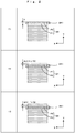
- FIG. 3 is a diagram schematically showing the operation of the image acquisition device.
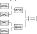
- FIG. 4 is a diagram schematically showing an inspection operation in the inspection apparatus. Note that a conveying direction of a workpiece W is referred to as a "sub-scanning direction Y", and a horizontal direction orthogonal to the sub-scanning direction Y is referred to as a "main scanning direction X".
- the inspection apparatus 1 includes an image acquisition device to inspect a rectangular parallelepiped metal component formed, for example, by forging or casting as a workpiece W.
- the image acquisition device obtains an inspection object image IM(IL1) and an inspection object image IM(IL2) captured by illuminating the rectangular parallelepiped workpiece W respectively from an upstream side and a downstream side in the sub-scanning direction Y while moving the workpiece W in the sub-scanning direction Y. Further, the inspection apparatus 1 inspects the workpiece W by comparing the inspection object images IM(IL1) and IM(IL2) obtained by the image acquisition device with reference images RF(IL1), RF(IL2) obtained in advance.
- the inspection apparatus 1 includes a body 2 and a control unit 3 constituted by a computer.
- the body 2 includes a conveyor belt 21 for linearly moving the workpiece W in the sub-scanning direction Y.
- the conveyor belt 21 is stretched over two unillustrated rollers.
- a drive motor 221 of a workpiece conveying mechanism 22 is connected to one roller.
- An encoder 222 is coupled to this drive motor 221 and outputs a detection signal of the operation of the drive motor 221 to the control unit 3. If the drive motor 221 operates in response to a conveyance command from the control unit 3, the conveyor belt 21 is driven with the workpiece W placed on a belt upper surface 21a as shown in FIG. 1 .
- the workpiece W is conveyed in the sub-scanning direction Y by way of an imaging area 23.
- a conveyance method of the workpiece W is not limited to this.
- the workpiece W may be conveyed by a stage configured to reciprocally move along the sub-scanning direction Y.
- An imager 24 and two light source units 251, 252 are fixedly arranged above the imaging area 23.
- the imager 24 is arranged at a position vertically above the imaging area 23 and can image the workpiece W passing through the imaging area 23 from above by an imaging element 241.
- the imaging element 241 is a line sensor in which a plurality of light receiving elements are arranged along the main scanning direction X, and has the strip-like imaging area 23 extending in the main scanning direction X as shown in FIG. 2 .
- the light source unit 251 a plurality of LEDs (Light Emitting Diodes) are arranged into a bar extending in the main scanning direction X.
- the light source unit 251 may be constituted by light sources of a type other than LEDs.
- This light source unit 251 functions as an upstream light source arranged upstream of and separated from the imager 24 in the sub-scanning direction Y and irradiates light toward the imaging area 23 obliquely from above on a side upstream of the imager 24.
- partial images captured in a state where only light from the upstream light source (light source unit 251) is irradiated in this way are referred to as "partial images Q2m(IL1)".
- partial images Q2m is a symbol for specifying the partial image and indicates 2 ⁇ m. That is, the partial images Q2m means partial images Q0, Q2, Q4 and the like.
- the other light source unit 252 is configured similarly to the light source unit 251, but is arranged at a position different from the light source unit 251 and has a light irradiation direction different from that of the light source unit 251. More particularly, the light source unit 252 is a downstream light source arranged downstream of and separated from the imager 24 in the sub-scanning direction Y and irradiates light toward the imaging area 23 obliquely from above on a side downstream of the imager 24.
- partial images captured in a state where only light from the downstream light source (light source unit 252) is irradiated in this way are referred to as "partial images Q2m+1(IL2)".
- partial images Q2m+1(IL2) are referred to as "partial images Q2m+1(IL2)".
- 2m+1 is a symbol for specifying the partial image and indicates 2 ⁇ m+1. That is, the partial images Q2m+1 mean partial images Q1, Q3, Q5 and the like.
- the partial images Q2m(IL1), Q2m+1 (IL2) are alternately captured in the following order every time the workpiece W moves in the sub-scanning direction Y by a unit distance ⁇ D obtained by dividing a size D of the imaging area 23 in the sub-scanning direction Y by the number "2" of the light sources as shown in FIG. 2 , i.e. by successively switching the light to be irradiated to the workpiece W at times T1, T2 and the like.
- adjacent times e.g.
- the partial image Q0(IL1) is captured in a state where only light from the upstream light source (light source unit 251) is irradiated at time T1
- the Q1(IL2) is captured in a state where only light from the downstream light source (light source unit 252) is irradiated at time T2.
- These two partial images Q0(IL1), Q1(IL2) are obtained using different light sources, but include images P1(IL1), P1(IL2) obtained by imaging the same area of the workpiece W. Further, at the following times T2 and T3, similar images P2(IL2), P2(IL1) are included. The same also applies thereafter.
- the partial images Q0, Q1, ... are captured by the imager 24 every time the light source is switched while the light source switch performed in the order of the upstream light source and the downstream light source is repeated,
- the light source switch of switching the light sources in the order of the upstream light source and the downstream light source as described above is repeated three times is described as an example.
- the partial images Q0(IL1), Q1(IL2), Q2(IL1), Q3(IL2), Q4(IL1) and Q5(IL2) are obtained and stored in the storage 33. If the partial images Q0 to Q5 are extracted for each light source from the storage 33 and the extracted partial images are combined, two composite images can be obtained.
- an inspection object image IM(IL1) when the workpiece W was imaged in the state where only the light from the upstream light source (light source unit 251) was irradiated, i.e. IM(IL1) P1(IL1)+P2(IL1)+ ... +P5(IL1), is obtained.
- an inspection object image IM(IL2) when the workpiece W was imaged in the state where only the light from the downstream light source (light source unit 252) was irradiated, i.e. IM(IL2) P1(IL2)+P2(IL2)+ ... +P5(IL2), is obtained.
- the thus obtained inspection object images IM(IL1), IM(IL2) are stored in the storage 33.
- the storage 33 is provided in the control unit 3 together with an image processor 31, the light source driver 32 and an arithmetic processor 34. As shown in FIG. 1 , besides the partial images Q and the inspection object images IM(IL1), IM(IL2) described above, the storage 33 stores the reference images RF(IL1), RF(IL2), various programs and the like in advance.
- the reference image RF(IL1) is an image obtained when a good workpiece W is imaged in a state where only light from the upstream light source (light source unit 251) is irradiated
- the reference image RF(IL2) is an image obtained when the good workpiece W is imaged in a state where only light from the downstream light source (light source unit 252) is irradiated.
- the programs stored in the storage 33 include an image acquisition program for obtaining the inspection object images IM(IL1), IM(IL2) and an inspection program for inspecting the workpiece W based on the inspection object images IM(IL1), IM(IL2).
- the arithmetic processor 34 performs various processes in accordance with these programs.
- the arithmetic processor 34 is constituted by a CPU (Central Processing Unit) and obtains images and inspects the workpiece W by controlling each component of the apparatus in accordance with the above programs. That is, the arithmetic processor 34 functions as the workpiece conveyance controller 341 for controlling workpiece conveyance by controlling the workpiece conveying mechanism 22, the light source switch controller 342 for switchingly turning on and off the light source units 251, 252, an inspection object image acquisitor 343 for obtaining the inspection object images IM(IL1), IM(IL2) and an inspector 344 for inspecting the workpiece.
- the workpiece conveyance controller 341 for controlling workpiece conveyance by controlling the workpiece conveying mechanism 22
- the light source switch controller 342 for switchingly turning on and off the light source units 251, 252
- an inspection object image acquisitor 343 for obtaining the inspection object images IM(IL1), IM(IL2) and an inspector 344 for inspecting the workpiece.
- the arithmetic processor 34 obtains the inspection object images IM(IL1), IM(IL2) after obtaining a plurality of partial images by switching the light sources while moving the workpiece W in the sub-scanning direction Y in accordance with the image acquisition program. Further, the arithmetic processor 34 inspects the workpiece based on the inspection object images IM(IL1), IM(IL2). A workpiece inspection operation is described below with reference to FIG. 4 after an image acquisition operation is described with reference to FIGS. 1 , 2 and 3 .
- the arithmetic processor 34 drives the conveyor belt 21 to convey the workpiece W on the conveyor belt 21 in the sub-scanning direction Y as shown in FIG. 1 and performs the following imaging operation in parallel.
- the imaging operation only the light source unit 251 is turned on with the light source unit 252 turned off until a partial area located on the tip of the workpiece W (hereinafter, referred to as a "tip partial area") reaches the imaging area 23.
- an image (P0+P1) of the tip partial area of the workpiece W is focused on a light receiving surface of the imaging element 241 as shown in an upper field of FIG. 2 .
- the above image P0 deviates toward a (-Y) side from the light receiving surface (dotted area in FIG. 2 ) of the imaging element 241 and the image P2 is newly located on the light receiving surface of the imaging element 241 as shown in a middle field of FIG. 2 .
- the light source unit 251 is turned off and the light source unit 252 is turned on in parallel with such a unit distance movement of the workpiece W.
- the light source illuminating the imaging area 23 and the periphery thereof is switched from the light source unit 251 to the light source unit 252 at the timing (time T2).
- the imager 24 captures the partial image Q1(IL2) of a partial area located in the imaging area 23 in a state illuminated only with light from the light source unit 252, i.e. light source light IL2, and writes the captured image in the storage 33.
- the above image P1 deviates toward the (-Y) side from the light receiving surface of the imaging element 241 and the image P3 is newly located on the light receiving surface of the imaging element 241 as shown in a lower field of FIG. 2 .
- the light source unit 252 is turned off and the light source unit 251 is turned on again in parallel with such a unit distance movement of the workpiece W.
- the light source illuminating the imaging area 23 and the periphery thereof is switched from the light source unit 252 to the light source unit 253 at the timing (time T3).
- the imager 24 captures the partial image Q2(IL1) of a partial area located in the imaging area 23 in a state illuminated only with light from the light source unit 251, i.e. light source light IL1, and writes the captured image in the storage 33. Also thereafter, the movement of the workpiece W and the light source switch are performed in parallel in a manner similar to the above and, as shown in FIG. 3 , the partial images are successively obtained at times T4 to T6:
- the arithmetic processor 34 extracts a plurality of the partial images Q obtained by the above imaging operation for each light source. Specifically, the partial images Q2m(IL1) are extracted in correspondence with the upstream light source, and the partial images Q2m+1(IL2) are extracted in correspondence with the downstream light source. Further, the arithmetic processor 34 deletes a part of the composite image obtained by combining the extracted partial images Q in accordance with the switching order of the light sources, obtains two inspection object images IM(IL1), IM(IL2) and writes the obtained images in the storage 33. In this way, the acquisition of the two two-dimensional images, i.e. the inspection object images IM(IL1), IM(IL2) for each light source is completed and the arithmetic processor 34 transitions to the inspection operation.
- the arithmetic processor 34 performs the following inspection operation in accordance with the inspection program. Specifically, as shown in FIG. 4 , the reference image RF(IL1) and the inspection object image IM(IL1) are read from the storage 33 and a difference between the both images is obtained. Similarly, the reference image RF(IL2) and the inspection object image IM(IL2) are read from the storage 33 and a difference between the both images is obtained. The arithmetic processor 34 determines whether or not there is any defect such as a scratch and a chip on a surface of the workpiece W based on difference images DF(IL1), DF(IL2) obtained in this way.
- pass/fail judgment of the workpiece W is made based on the difference images
- a pass/fail judgment method is not limited to this.
- Another method for judgment based on the inspection object images IM(IL1), IM(IL2) may be used.
- the inspection object images IM(IL1), IM(IL2) are obtained by switching the light sources while moving the workpiece W in this embodiment, a time required for image acquisition can be drastically shortened.
- a plurality of partial images Q2m(IL1) captured by irradiating the light from the light source unit 251 and a plurality of partial images Q2m+1(IL2) captured by irradiating the light from the light source unit 252 are shifted by the unit distance ⁇ D.
- the inspection object images IM(IL1), IM(IL2) are formed by extracting the partial images Q for each light source, combining the extracted partial images Q and deleting partial images from the composite images.
- the line sensor is used as the imaging element 241
- the partial images obtained by imaging the imaging area 23 is transferred to the image processor 31 at a relatively high transfer rate.
- the partial images Q2m(IL1), Q2m+1(IL2) can be reliably transferred.
- two-dimensional images for each light source i.e. the inspection object images IM(IL1), IM(IL2), are obtained by one imager 24 and the device configuration can be simplified as compared to the device described in patent literature 1 using a plurality of imagers.
- the inspection object images IM(IL1), IM(IL2) can be obtained in a short time, a time required for the inspection of the workpiece W can also be drastically shortened.
- the sub-scanning direction Y and the main scanning direction X respectively correspond to a "first direction” and a “second direction” of the invention
- the conveyor belt 21 and the workpiece conveying mechanism 22 provided to move the workpiece W in the sub-scanning direction Y function as a "mover” of the invention.
- the light source units 251, 252 respectively function as a "first light source” and a “second light source” of the invention, but a turn-on order may be switched.
- the light source units 251, 252 respectively function as the "second light source” and the "first light source” of the invention.
- the two light source units 251, 252, the imager 24, the storage 33 and the arithmetic processor 34 including the light source switch controller 342 and the object image acquisitor 343 function as an "image acquisition device" of the invention.
- the invention is not limited to the above embodiment and various changes other than the aforementioned ones can be made without departing from the gist of the invention.
- the invention is applied to the inspection apparatus 1 for inspecting the workpiece W by obtaining the inspection object images IM(IL1), IM(IL2) using two light source units 251, 252 in the above embodiment, the invention can be applied also to an inspection apparatus including three or more light source units. An inspection apparatus including three light source units is described below with reference to FIGS. 5 to 8 .
- FIG. 5 is a diagram showing the configuration of an inspection apparatus equipped with a second embodiment of the image acquisition device according to the invention.
- FIG. 6 is a schematic diagram showing a positional relationship of a workpiece and an imaging element in the inspection apparatus.
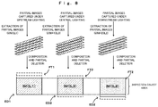
- FIGS. 7 and 8 are diagrams schematically showing the operation of the image acquisition device.
- the light source unit 253 is provided downstream of and adjacent to an imager 24 in a sub-scanning direction Y.
- a plurality of LEDs are arranged into a bar extending in a main scanning direction X, similarly to the light source units 251, 252.
- This light source unit 253 functions as a central light source for irradiating light toward an imaging area 23 substantially vertically from above at an intermediate position between the light source units 251, 252.
- an arithmetic processor 34 drives the conveyor belt 21 to convey the workpiece W on the conveyor belt 21 in the sub-scanning direction Y as shown in FIG. 5 , and performs the following imaging operation.
- the light source unit 251 is turned on with the light source units 252, 253 turned off until a tip partial area of the workpiece W reaches the imaging area 23. Thereafter, at a timing (time T1) at which the tip partial area of the workpiece W arrives at the imaging area 23, an image of the tip partial area of the workpiece W is focused on a light receiving surface of an imaging element 241 as shown in an upper field of FIG. 6 .
- the workpiece W is further moved by the unit distance ⁇ D in the sub-scanning direction Y and the light source unit 253 is turned off and the light source unit 252 is turned on according to this movement.
- the partial images Q are captured by the imager 24 every time the light source is switched while repeating the light source switch in an order of the upstream light source, the central light source and the downstream light source and, as shown in FIG. 7 , the partial images Q are obtained and written in the storage 33 at times T4 and the like.
- the imaging operation is stopped after the light source switch described above is repeated a number of times set in advance.
- the arithmetic processor 34 extracts a plurality of partial images obtained by the imaging operation for each light source as in the first embodiment. That is, the arithmetic processor 34 extracts the partial images Q3m(IL1) for the upstream light source, extracts the partial images Q3m+1(IL3) for the central light source and extracts the partial images Q3m+2(IL2) for the downstream light source.
- "3m" is a symbol for specifying the partial image and indicates 3 ⁇ m. That is, the partial images Q3m means partial images Q0, Q3, Q6 and the like, the partial images Q3m+1 means partial images Q1, Q4, Q7 and the like, and the partial images Q3m+2 means partial images Q2, Q5, Q8 and the like.
- the arithmetic processor 34 obtains three inspection object images IM(IL1), IM(IL3) and IM(IL2) by deleting a part of a composite image obtained by combining the partial images extracted for each light source according to the light source switching order and writes the obtained images in the storage 33.
- An example of this operation is schematically shown in FIG. 8 .
- the arithmetic processor 34 deletes a part of a partial image FT1 captured earliest, out of the composite image formed by the partial images Q3m(IL1) extracted for the upstream light source, more particularly images (parts indicated by broken line in FIG. 8 ) located on a downstream side (upper side in FIG. 8 ) out of images included in the partial image FT1.
- a part of a partial image ED2 captured at last, contrary to the above case, more particularly images (parts indicated by broken line in FIG. 8 ) located on an upstream side (lower side in FIG.
- a partial image ED1 captured at last, out of the composite image formed by the partial images Q3m(IL1), and a partial image FT2 captured earliest, out of the composite image formed by the partial images Q3m+2(IL2), are not deleted and included in an inspection object area.
- the arithmetic processor 34 transitions to an inspection operation and inspects the workpiece W as in the first embodiment.
- the inspection object images IM(IL1), IM(IL3) and IM(IL2) are obtained by switching the light sources (changing illumination) while moving the workpiece W as in the first embodiment, a time required for image acquisition can be drastically shortened.
- three light source units 251, 252 and 253 are provided and respectively function as the "first light source”, the "second light source” and a “third light source” of the invention in the second embodiment, but a turn-on order of the light sources is arbitrary without being limited to the turn-on order of the light source units 251, 253 and 252.
- the inspection object images are obtained and the workpiece W is inspected while the workpiece W is linearly moved in the sub-scanning direction Y in the above embodiments
- the application of the invention is not limited to this.
- the invention can be applied also to an inspection apparatus for obtaining inspection object images and inspecting a workpiece W while rotating the workpiece W in a rotation direction R as shown in FIG. 9 .
- FIG. 9 is a diagram showing the configuration of an inspection apparatus equipped with a third embodiment of the image acquisition device according to the invention.
- the third embodiment largely differs from the first embodiment in that the workpiece W is a metal component having a rotationally symmetrical shape such as a gear and in that a moving direction of the workpiece W is changed from the sub-scanning direction Y to the rotation direction R.
- the other configuration is basically the same as in the first embodiment.
- the workpiece W is held and rotationally moved by a workpiece rotation driving mechanism 26 as shown in FIG. 9 .
- This workpiece rotation driving mechanism 26 includes an unillustrated chuck and holds the workpiece W with a rotation center axis AXc of the chuck and a rotational symmetry axis AXw of the workpiece W coincided.
- the chuck is coupled to a drive motor 261 and rotates the workpiece W about the rotation center axis AXc by being rotated by the drive motor 261.
- an encoder 262 is mounted on the drive motor 261 to detect the positon of the workpiece W in the rotation direction R with high accuracy.
- an imager 24 and light source units 251, 252 are arranged vertically above the work W. As shown in FIG. 9 , the imager 24 is provided to extend radially outward with respect to the rotational symmetry axis AXw of the workpiece W. Thus, an imaging area 23 of the workpiece W can be imaged by an imaging element 241 of the imager 24 while the workpiece W is rotated. Further, the light source units 251, 252 are respectively arranged upstream of and downstream of the imager 24 in the rotation direction R. In the light source unit 251, 252, a plurality of LEDs are arranged into a bar extending in a direction parallel to an extending direction of the imager 24.
- a partial area of the workpiece W located in the imaging area 23 and the periphery thereof are respectively illuminated by the light source unit 251 and a partial image is captured.
- a partial area of the workpiece W located in the imaging area 23 and the periphery thereof are respectively illuminated by the light source unit 252 and a partial image is captured.
- partial images Q2m(IL1), Q2m+1(IL2) are obtained by switching the light sources in parallel with a rotational movement of the workpiece W
- a plurality of partial images are extracted for each light source, and parts of composite images of those are deleted according to a switching order of the light sources to obtain inspection object images IM(IL1), IM(IL2).
- the inspection object images IM(IL1), IM(IL2) are respectively compared to reference images RF(IL1), RF(IL2) to perform pass/fail judgment for the workpiece W.
- the inspection object images IM(IL1), IM(IL2) are obtained by switching the light sources (changing illumination) while moving the workpiece W as in the first embodiment.
- a time required for image acquisition can be drastically shortened.
- the rotation direction R corresponds to the "first direction” of the invention
- a radial direction of the workpiece W corresponds to the "second direction” of the invention.
- a forged component, a cast component or a metal component such as a gear serves as the workpiece W and the workpiece W is inspected by obtaining the inspection object image thereof for each light source in the above embodiments
- the constituent material, the shape and the like of the workpiece W are not particularly limited.
- a resin component or a rubber component may serve as the workpiece W and the invention may be applied to a device for obtaining inspection object images for inspection.
- a component having a disk shape or a ring shape may serve as the workpiece W and the invention may be applied to a device for obtaining inspection object images for inspection.
- the image acquisition device and an image acquisition method according to the invention may be applied to a device for forming a composite image by a photometric stereo method.
- the photometric stereo method it is necessary to provide three or more light source units and obtain three or more two-dimensional images.
- This invention can be applied to an image acquisition technique for obtaining images of an object for each light source in a state where the object is successively irradiated with light from N (N is a natural number equal to or greater than 2) light sources having mutually different irradiation directions and devices in general equipped with this technique.
Landscapes
- Engineering & Computer Science (AREA)
- Signal Processing (AREA)
- Physics & Mathematics (AREA)
- General Physics & Mathematics (AREA)
- Multimedia (AREA)
- Computer Vision & Pattern Recognition (AREA)
- Theoretical Computer Science (AREA)
- Life Sciences & Earth Sciences (AREA)
- Health & Medical Sciences (AREA)
- Chemical & Material Sciences (AREA)
- Analytical Chemistry (AREA)
- Biochemistry (AREA)
- General Health & Medical Sciences (AREA)
- Immunology (AREA)
- Pathology (AREA)
- Quality & Reliability (AREA)
- Investigating Materials By The Use Of Optical Means Adapted For Particular Applications (AREA)
- Image Input (AREA)
Abstract
Description
- This invention relates to an image acquisition technique for obtaining an image of an object (hereinafter, referred to as a "workpiece") for each light source in a state where the object is successively irradiated with light from N (N is a natural number equal to or greater than 2) light sources having mutually different irradiation directions and an inspection technique for inspecting a workpiece based on a plurality of images obtained by the image acquisition technique. Note that an "image of an object for each light source" means an image obtained by imaging the object in a state where the object is irradiated only with the light from each light source, and N object images are obtained in a device having N light sources.
- The disclosure of Japanese Patent Application No.
2018-018125 filed on February 5, 2018 - A device is known which inspects a workpiece based on a plurality of images obtained by imaging the three-dimensional workpiece such as a metal component, a resin component or a rubber component from various angles. For example, a plurality of light source units for respectively irradiating light to a workpiece held on a stage from a plurality of directions are provided in an inspection apparatus of
patent literature 1. After the workpiece is positioned by rotating the stage by a predetermined angle, light is irradiated to illuminate the workpiece in a stationary state from the light source units and images of the workpiece are obtained by an imager. The workpiece is inspected based on a plurality of images obtained in this way. - [Patent literature 1]
JP 2016-57075A - In the above conventional technique, each light source is switchingly turned on and off every time the workpiece is moved, illumination is changed by successively irradiating light to the workpiece in the stationary state from each of the plurality of light sources, and the image is obtained for each light source. By alternately performing a movement of the workpiece and an illumination change by switching the light sources in this way, images necessary for inspection are obtained. Thus, there is a limit to the shortening of a time required for image acquisition and the shortening of this time is desired. Further, such a request is not limited to workpiece inspection apparatus and a similar request is made, for example, for devices using a photometric stereo method. That is, in the photometric stereo method, an image of a workpiece is obtained for each light source in a state where light is successively irradiated to the workpiece from three or more light sources having mutually different irradiation directions and those captured images are combined. Thus, it is important in enhancing the operation efficiency of the device to obtain the image of the workpiece for each light source in a short time.
- This invention was developed in view of the above problem and aims to shorten a time required to obtain an image of an object for each light source in a state where light is successively irradiated to the object from N (N is a natural number equal to or greater than 2) light sources having mutually different irradiation directions.
- A first aspect of the invention is an image acquisition device that obtains images of an object for each light source in a state where the object is successively irradiated with light from N (N is an natural number equal to or greater than 2) light sources having mutually different irradiation directions. The device comprises: a mover that moves the object in a first direction; an imager having a strip-like imaging area extending in a second direction orthogonal to the first direction, the imager obtaining a partial image of the object by imaging a partial area of the object passing through the imaging area; a light source switch controller that successively switches the light to be irradiated to the object every time the object is moved in the first direction by a unit distance obtained by dividing a size of the imaging area in the first direction by the number N of the light sources; a storage that stories the partial images obtained by the imager every time the light is switched; and an object image acquisitor that obtains N images of the object by deleting a part of a composite image obtained by combining a plurality of the partial images stored in the storage for each light source according to a switching order of the light sources.
- A second aspect of the invention is an image acquisition method that obtains images of an object for each light source in a state where the object is successively irradiated with light from N (N is an natural number equal to or greater than 2) light sources having mutually different irradiation directions while the object is moved in a first direction, the method comprises: preparing an imager having a strip-like imaging area extending in a second direction orthogonal to the first direction, the imager obtaining a partial image of the object by imaging a partial area of the object passing through the imaging area; successively switching the light to be irradiated to the object every time the object is moved in the first direction by a unit distance obtained by dividing a size of the imaging area in the first direction by the number N of the light sources and storing an image obtained by imaging the partial area by the imager as the partial image every time the light is switched; and forming a composite image by combining a plurality of the partial images stored in the storage for each light source and obtaining N images of the object by deleting parts of the composite images according to a switching order of the light sources.
- A third aspect of the invention is an inspection apparatus that comprises: the image acquisition device; and an inspector for inspecting the object based on the N images of the object obtained by the image acquisition device.
- In the invention thus configured, a movement of the object and the light source switch are performed in parallel and a plurality of partial images are obtained. An image of the object is obtained by deleting a part according to the switching order of the light sources from a composite image obtained by combining the plurality of partial images for each light source. As a result, as many images of the object illuminated only by one of the N light sources as the N light sources, i.e. N images of the object, are obtained.
- As described above, since the image of the object for each light source is obtained by performing the movement of the object and the light source switch in parallel, a time required for image acquisition for each light source can be shortened.
- All of a plurality of constituent elements of each aspect of the invention described above are not essential and some of the plurality of constituent elements can be changed, deleted or replaced by new other constituent elements or limitation contents can be partially deleted as appropriate to solve some or all of the problems described above or achieve some or all of effects described in this specification. Further, some or all of technical features included in one aspect of the invention described above can be combined with some or all of technical features included in another aspect of the invention described above into one independent aspect of the invention to solve some or all of the problems described above or achieve some or all of effects described in this specification.
-
-
FIG. 1 is a diagram showing the configuration of an inspection apparatus equipped with a first embodiment of an image acquisition device according to the invention. -
FIG. 2 is a schematic diagram showing a positional relationship of a workpiece and an imaging element in the inspection apparatus. -
FIG. 3 is a diagram schematically showing the operation of the image acquisition device. -
FIG. 4 is a diagram schematically showing an inspection operation in the inspection apparatus. -
FIG. 5 is a diagram showing the configuration of an inspection apparatus equipped with a second embodiment of the image acquisition device according to the invention. -
FIG. 6 is a schematic diagram showing a positional relationship of a workpiece and an imaging element in the inspection apparatus. -
FIG. 7 is a diagram schematically showing the operation of the image acquisition device. -
FIG. 8 is a diagram schematically showing the operation of the image acquisition device. -
FIG. 9 is a diagram showing the configuration of an inspection apparatus equipped with a third embodiment of the image acquisition device according to the invention. -
FIG. 1 is a diagram showing the configuration of an inspection apparatus equipped with a first embodiment of an image acquisition device according to the invention.FIG. 2 is a schematic diagram showing a positional relationship of a workpiece and an imaging element in the inspection apparatus.FIG. 3 is a diagram schematically showing the operation of the image acquisition device.FIG. 4 is a diagram schematically showing an inspection operation in the inspection apparatus. Note that a conveying direction of a workpiece W is referred to as a "sub-scanning direction Y", and a horizontal direction orthogonal to the sub-scanning direction Y is referred to as a "main scanning direction X". - The
inspection apparatus 1 includes an image acquisition device to inspect a rectangular parallelepiped metal component formed, for example, by forging or casting as a workpiece W. The image acquisition device obtains an inspection object image IM(IL1) and an inspection object image IM(IL2) captured by illuminating the rectangular parallelepiped workpiece W respectively from an upstream side and a downstream side in the sub-scanning direction Y while moving the workpiece W in the sub-scanning direction Y. Further, theinspection apparatus 1 inspects the workpiece W by comparing the inspection object images IM(IL1) and IM(IL2) obtained by the image acquisition device with reference images RF(IL1), RF(IL2) obtained in advance. - As shown in
FIG. 1 , theinspection apparatus 1 includes abody 2 and acontrol unit 3 constituted by a computer. Thebody 2 includes aconveyor belt 21 for linearly moving the workpiece W in the sub-scanning direction Y. Theconveyor belt 21 is stretched over two unillustrated rollers. Adrive motor 221 of aworkpiece conveying mechanism 22 is connected to one roller. Anencoder 222 is coupled to thisdrive motor 221 and outputs a detection signal of the operation of thedrive motor 221 to thecontrol unit 3. If thedrive motor 221 operates in response to a conveyance command from thecontrol unit 3, theconveyor belt 21 is driven with the workpiece W placed on a beltupper surface 21a as shown inFIG. 1 . In this way, the workpiece W is conveyed in the sub-scanning direction Y by way of animaging area 23. Note that although the workpiece W is conveyed by the belt in this embodiment, a conveyance method of the workpiece W is not limited to this. For example, the workpiece W may be conveyed by a stage configured to reciprocally move along the sub-scanning direction Y. - An
imager 24 and twolight source units imaging area 23. Theimager 24 is arranged at a position vertically above theimaging area 23 and can image the workpiece W passing through theimaging area 23 from above by animaging element 241. Theimaging element 241 is a line sensor in which a plurality of light receiving elements are arranged along the main scanning direction X, and has the strip-like imaging area 23 extending in the main scanning direction X as shown inFIG. 2 . - In the
light source unit 251, a plurality of LEDs (Light Emitting Diodes) are arranged into a bar extending in the main scanning direction X. Here, thelight source unit 251 may be constituted by light sources of a type other than LEDs. Thislight source unit 251 functions as an upstream light source arranged upstream of and separated from theimager 24 in the sub-scanning direction Y and irradiates light toward theimaging area 23 obliquely from above on a side upstream of theimager 24. Thus, if only thelight source unit 251 is turned on by alight source driver 32 of thecontrol unit 3, light from thelight source unit 251 is irradiated to theimaging area 23 and a partial area of the workpiece W located in theimaging area 23 and the periphery thereof are respectively illuminated by thelight source unit 251. An image of the partial area illuminated in this way is captured. Note that, in this embodiment, partial images captured in a state where only light from the upstream light source (light source unit 251) is irradiated in this way are referred to as "partial images Q2m(IL1)". "2m" is a symbol for specifying the partial image and indicates 2×m. That is, the partial images Q2m means partial images Q0, Q2, Q4 and the like. - The other
light source unit 252 is configured similarly to thelight source unit 251, but is arranged at a position different from thelight source unit 251 and has a light irradiation direction different from that of thelight source unit 251. More particularly, thelight source unit 252 is a downstream light source arranged downstream of and separated from theimager 24 in the sub-scanning direction Y and irradiates light toward theimaging area 23 obliquely from above on a side downstream of theimager 24. Thus, if only thelight source unit 252 is turned on by thelight source driver 32 of thecontrol unit 3, light is irradiated to theimaging area 23 in the irradiation direction different from the one when thelight source unit 251 is turned on, and a partial area of the workpiece W located in theimaging area 23 and the periphery thereof are respectively illuminated by thelight source unit 252. An image of the partial area illuminated in this way is captured. Note that, in this embodiment, partial images captured in a state where only light from the downstream light source (light source unit 252) is irradiated in this way are referred to as "partial images Q2m+1(IL2)". "2m+1" is a symbol for specifying the partial image and indicates 2×m+1. That is, the partial images Q2m+1 mean partial images Q1, Q3, Q5 and the like. - These two
light source units light source driver 32 in response to a command from a lightsource switch controller 342 of thecontrol unit 3. In this embodiment, the partial images Q2m(IL1), Q2m+1 (IL2) are alternately captured in the following order every time the workpiece W moves in the sub-scanning direction Y by a unit distance ΔD obtained by dividing a size D of theimaging area 23 in the sub-scanning direction Y by the number "2" of the light sources as shown inFIG. 2 , i.e. by successively switching the light to be irradiated to the workpiece W at times T1, T2 and the like. Here, if adjacent times, e.g. times T1 and T2 are focused, the following is found. The partial image Q0(IL1) is captured in a state where only light from the upstream light source (light source unit 251) is irradiated at time T1, and the Q1(IL2) is captured in a state where only light from the downstream light source (light source unit 252) is irradiated at time T2. These two partial images Q0(IL1), Q1(IL2) are obtained using different light sources, but include images P1(IL1), P1(IL2) obtained by imaging the same area of the workpiece W. Further, at the following times T2 and T3, similar images P2(IL2), P2(IL1) are included. The same also applies thereafter. Thus, if the partial images Q0, Q1, ... are captured by theimager 24 every time the light source is switched while the light source switch performed in the order of the upstream light source and the downstream light source is repeated, - Time T1: partial image Q0(IL1) = image P0(IL1)+image P1(IL1)
- Time T2: partial image Q1(IL2) = image P1(IL2)+image P2(IL2)
- Time T3: partial image Q2(IL1) = image P2(IL1)+image P3(IL1)
- Time T4: partial image Q3(IL2) = image P3(IL2)+image P4(IL2)
- Here, to facilitate the understanding of technical contents of this embodiment, a case where the light source switch of switching the light sources in the order of the upstream light source and the downstream light source as described above is repeated three times is described as an example. By performing a movement of the workpiece W and the light source switch in parallel in this way, the partial images Q0(IL1), Q1(IL2), Q2(IL1), Q3(IL2), Q4(IL1) and Q5(IL2) are obtained and stored in the
storage 33. If the partial images Q0 to Q5 are extracted for each light source from thestorage 33 and the extracted partial images are combined, two composite images can be obtained. By deleting a part of the partial image Q0(IL1) captured earliest, out of the composite image of the upstream light source turned on earlier, more specifically the image P0(IL1), an inspection object image IM(IL1) when the workpiece W was imaged in the state where only the light from the upstream light source (light source unit 251) was irradiated, i.e.
IM(IL1) = P1(IL1)+P2(IL1)+ ... +P5(IL1),
is obtained. Further, by deleting a part of the partial image Q5(IL2) captured at last, out of the composite image of the downstream light source turned on later, more specifically the image P6(IL2), an inspection object image IM(IL2) when the workpiece W was imaged in the state where only the light from the downstream light source (light source unit 252) was irradiated, i.e.
IM(IL2) = P1(IL2)+P2(IL2)+ ... +P5(IL2),
is obtained. The thus obtained inspection object images IM(IL1), IM(IL2) are stored in thestorage 33. - The
storage 33 is provided in thecontrol unit 3 together with animage processor 31, thelight source driver 32 and anarithmetic processor 34. As shown inFIG. 1 , besides the partial images Q and the inspection object images IM(IL1), IM(IL2) described above, thestorage 33 stores the reference images RF(IL1), RF(IL2), various programs and the like in advance. The reference image RF(IL1) is an image obtained when a good workpiece W is imaged in a state where only light from the upstream light source (light source unit 251) is irradiated, and the reference image RF(IL2) is an image obtained when the good workpiece W is imaged in a state where only light from the downstream light source (light source unit 252) is irradiated. Further, the programs stored in thestorage 33 include an image acquisition program for obtaining the inspection object images IM(IL1), IM(IL2) and an inspection program for inspecting the workpiece W based on the inspection object images IM(IL1), IM(IL2). Thearithmetic processor 34 performs various processes in accordance with these programs. - The
arithmetic processor 34 is constituted by a CPU (Central Processing Unit) and obtains images and inspects the workpiece W by controlling each component of the apparatus in accordance with the above programs. That is, thearithmetic processor 34 functions as theworkpiece conveyance controller 341 for controlling workpiece conveyance by controlling theworkpiece conveying mechanism 22, the lightsource switch controller 342 for switchingly turning on and off thelight source units object image acquisitor 343 for obtaining the inspection object images IM(IL1), IM(IL2) and aninspector 344 for inspecting the workpiece. In this embodiment, thearithmetic processor 34 obtains the inspection object images IM(IL1), IM(IL2) after obtaining a plurality of partial images by switching the light sources while moving the workpiece W in the sub-scanning direction Y in accordance with the image acquisition program. Further, thearithmetic processor 34 inspects the workpiece based on the inspection object images IM(IL1), IM(IL2). A workpiece inspection operation is described below with reference toFIG. 4 after an image acquisition operation is described with reference toFIGS. 1 ,2 and3 . - If a workpiece W to be inspected is transferred to the
conveyor belt 21, thearithmetic processor 34 drives theconveyor belt 21 to convey the workpiece W on theconveyor belt 21 in the sub-scanning direction Y as shown inFIG. 1 and performs the following imaging operation in parallel. In the imaging operation, only thelight source unit 251 is turned on with thelight source unit 252 turned off until a partial area located on the tip of the workpiece W (hereinafter, referred to as a "tip partial area") reaches theimaging area 23. Thereafter, at a timing (time T1) at which the tip partial area of the workpiece W arrives at theimaging area 23, an image (P0+P1) of the tip partial area of the workpiece W is focused on a light receiving surface of theimaging element 241 as shown in an upper field ofFIG. 2 . Thus, theimager 24 captures an image of the partial area located in theimaging area 23, i.e. the partial image Q0(IL1) (= P0(IL1)+P1(IL1)) in a state illuminated only with light from thelight source unit 251, i.e. light source light IL1, and writes the captured image in thestorage 33. - Subsequent to this, at a timing (time T2) at which the workpiece W is moved by the unit distance ΔD in the sub-scanning direction Y, the above image P0 deviates toward a (-Y) side from the light receiving surface (dotted area in
FIG. 2 ) of theimaging element 241 and the image P2 is newly located on the light receiving surface of theimaging element 241 as shown in a middle field ofFIG. 2 . Thelight source unit 251 is turned off and thelight source unit 252 is turned on in parallel with such a unit distance movement of the workpiece W. By this light source switch, the light source illuminating theimaging area 23 and the periphery thereof is switched from thelight source unit 251 to thelight source unit 252 at the timing (time T2). Accordingly, theimager 24 captures the partial image Q1(IL2) of a partial area located in theimaging area 23 in a state illuminated only with light from thelight source unit 252, i.e. light source light IL2, and writes the captured image in thestorage 33. - At a timing (time T3) at which the workpiece W is moved in the sub-scanning direction Y by one partial image area, the above image P1 deviates toward the (-Y) side from the light receiving surface of the
imaging element 241 and the image P3 is newly located on the light receiving surface of theimaging element 241 as shown in a lower field ofFIG. 2 . Thelight source unit 252 is turned off and thelight source unit 251 is turned on again in parallel with such a unit distance movement of the workpiece W. By this light source switch, the light source illuminating theimaging area 23 and the periphery thereof is switched from thelight source unit 252 to thelight source unit 253 at the timing (time T3). Accordingly, theimager 24 captures the partial image Q2(IL1) of a partial area located in theimaging area 23 in a state illuminated only with light from thelight source unit 251, i.e. light source light IL1, and writes the captured image in thestorage 33. Also thereafter, the movement of the workpiece W and the light source switch are performed in parallel in a manner similar to the above and, as shown inFIG. 3 , the partial images are successively obtained at times T4 to T6: - Time T4: Q3(IL2) = image P3(IL2)+image P4(IL2)
- Time T5: Q4(IL1) = image P4(IL1)+image P5(IL1)
- Time T6: Q5(IL2) = image P5(IL2)+image P6(IL2),
- Subsequently, the
arithmetic processor 34 extracts a plurality of the partial images Q obtained by the above imaging operation for each light source. Specifically, the partial images Q2m(IL1) are extracted in correspondence with the upstream light source, and the partial images Q2m+1(IL2) are extracted in correspondence with the downstream light source. Further, thearithmetic processor 34 deletes a part of the composite image obtained by combining the extracted partial images Q in accordance with the switching order of the light sources, obtains two inspection object images IM(IL1), IM(IL2) and writes the obtained images in thestorage 33. In this way, the acquisition of the two two-dimensional images, i.e. the inspection object images IM(IL1), IM(IL2) for each light source is completed and thearithmetic processor 34 transitions to the inspection operation. - The
arithmetic processor 34 performs the following inspection operation in accordance with the inspection program. Specifically, as shown inFIG. 4 , the reference image RF(IL1) and the inspection object image IM(IL1) are read from thestorage 33 and a difference between the both images is obtained. Similarly, the reference image RF(IL2) and the inspection object image IM(IL2) are read from thestorage 33 and a difference between the both images is obtained. Thearithmetic processor 34 determines whether or not there is any defect such as a scratch and a chip on a surface of the workpiece W based on difference images DF(IL1), DF(IL2) obtained in this way. Note that although pass/fail judgment of the workpiece W is made based on the difference images, a pass/fail judgment method is not limited to this. Another method for judgment based on the inspection object images IM(IL1), IM(IL2) may be used. - As described above, since the inspection object images IM(IL1), IM(IL2) are obtained by switching the light sources while moving the workpiece W in this embodiment, a time required for image acquisition can be drastically shortened.
- Further, a plurality of partial images Q2m(IL1) captured by irradiating the light from the
light source unit 251 and a plurality of partial images Q2m+1(IL2) captured by irradiating the light from thelight source unit 252 are shifted by the unit distance ΔD. As described above, the inspection object images IM(IL1), IM(IL2) are formed by extracting the partial images Q for each light source, combining the extracted partial images Q and deleting partial images from the composite images. Thus, an inspection object image of an area of the workpiece W to be inspected can be accurately obtained. - Further, since the line sensor is used as the
imaging element 241, the partial images obtained by imaging theimaging area 23 is transferred to theimage processor 31 at a relatively high transfer rate. Thus, even if the workpiece W is moved at a relative high speed, the partial images Q2m(IL1), Q2m+1(IL2) can be reliably transferred. - Further, in this embodiment, two-dimensional images for each light source, i.e. the inspection object images IM(IL1), IM(IL2), are obtained by one
imager 24 and the device configuration can be simplified as compared to the device described inpatent literature 1 using a plurality of imagers. - Furthermore, since the inspection object images IM(IL1), IM(IL2) can be obtained in a short time, a time required for the inspection of the workpiece W can also be drastically shortened.
- As just described, in this embodiment, the sub-scanning direction Y and the main scanning direction X respectively correspond to a "first direction" and a "second direction" of the invention, and the
conveyor belt 21 and theworkpiece conveying mechanism 22 provided to move the workpiece W in the sub-scanning direction Y function as a "mover" of the invention. Further, thelight source units light source units conveyor belt 21 and workpiece conveying mechanism 22), the twolight source units imager 24, thestorage 33 and thearithmetic processor 34 including the lightsource switch controller 342 and theobject image acquisitor 343 function as an "image acquisition device" of the invention. Further, since twolight source units - Note that the invention is not limited to the above embodiment and various changes other than the aforementioned ones can be made without departing from the gist of the invention. For example, although the invention is applied to the
inspection apparatus 1 for inspecting the workpiece W by obtaining the inspection object images IM(IL1), IM(IL2) using twolight source units FIGS. 5 to 8 . -
FIG. 5 is a diagram showing the configuration of an inspection apparatus equipped with a second embodiment of the image acquisition device according to the invention.FIG. 6 is a schematic diagram showing a positional relationship of a workpiece and an imaging element in the inspection apparatus.FIGS. 7 and8 are diagrams schematically showing the operation of the image acquisition device. The second embodiment largely differs from the first embodiment in that anotherlight source unit 253 is added besideslight source units - In the second embodiment, as shown in
FIG. 5 , thelight source unit 253 is provided downstream of and adjacent to animager 24 in a sub-scanning direction Y. In thelight source unit 253, a plurality of LEDs are arranged into a bar extending in a main scanning direction X, similarly to thelight source units light source unit 253 functions as a central light source for irradiating light toward animaging area 23 substantially vertically from above at an intermediate position between thelight source units - If a workpiece W to be inspected is transferred to a
conveyor belt 21, anarithmetic processor 34 drives theconveyor belt 21 to convey the workpiece W on theconveyor belt 21 in the sub-scanning direction Y as shown inFIG. 5 , and performs the following imaging operation. - In the second embodiment, as in the first embodiment, only the
light source unit 251 is turned on with thelight source units imaging area 23. Thereafter, at a timing (time T1) at which the tip partial area of the workpiece W arrives at theimaging area 23, an image of the tip partial area of the workpiece W is focused on a light receiving surface of animaging element 241 as shown in an upper field ofFIG. 6 . Thus, theimager 24 captures an image of the partial area located in theimaging area 23, i.e. a partial image Q0 (= P0(IL1)+P1(IL1)+P2(IL1)), in a state illuminated only with light from thelight source unit 251, i.e. light source light IL1, and writes the captured image in a storage 33 (seeFIG. 7 ). - Subsequent to this, the workpiece W is moved by the unit distance ΔD (= D/3) in the sub-scanning direction Y and the
light source unit 251 is turned off and thelight source unit 253 is turned on according to this movement. At this timing (time T2), theimager 24 captures a partial image Q1 (= P1(IL3)+P2(IL3)+P3(IL3)) of a partial area located in theimaging area 23 in a state illuminated only with light from thelight source unit 253, i.e. light source light IL3, and writes the captured image in thestorage 33. - The workpiece W is further moved by the unit distance ΔD in the sub-scanning direction Y and the
light source unit 253 is turned off and thelight source unit 252 is turned on according to this movement. At this timing (time T3), theimager 24 captures a partial image Q2 (= P2(IL2)+P3(IL2)+P4(IL2)) of a partial area located in theimaging area 23 in a state illuminated only with light from thelight source unit 252, i.e. light source light IL2, and writes the captured image in thestorage 33. - Also thereafter, the partial images Q are captured by the
imager 24 every time the light source is switched while repeating the light source switch in an order of the upstream light source, the central light source and the downstream light source and, as shown inFIG. 7 , the partial images Q are obtained and written in thestorage 33 at times T4 and the like. The imaging operation is stopped after the light source switch described above is repeated a number of times set in advance. - Subsequently, the
arithmetic processor 34 extracts a plurality of partial images obtained by the imaging operation for each light source as in the first embodiment. That is, thearithmetic processor 34 extracts the partial images Q3m(IL1) for the upstream light source, extracts the partial images Q3m+1(IL3) for the central light source and extracts the partial images Q3m+2(IL2) for the downstream light source. "3m" is a symbol for specifying the partial image and indicates 3×m. That is, the partial images Q3m means partial images Q0, Q3, Q6 and the like, the partial images Q3m+1 means partial images Q1, Q4, Q7 and the like, and the partial images Q3m+2 means partial images Q2, Q5, Q8 and the like. - Then, the
arithmetic processor 34 obtains three inspection object images IM(IL1), IM(IL3) and IM(IL2) by deleting a part of a composite image obtained by combining the partial images extracted for each light source according to the light source switching order and writes the obtained images in thestorage 33. An example of this operation is schematically shown inFIG. 8 . - As shown in
FIG. 8 , thearithmetic processor 34 deletes a part of a partial image FT1 captured earliest, out of the composite image formed by the partial images Q3m(IL1) extracted for the upstream light source, more particularly images (parts indicated by broken line inFIG. 8 ) located on a downstream side (upper side inFIG. 8 ) out of images included in the partial image FT1. On the other hand, for the composite image formed by the partial images Q3+2(IL2) extracted for the downstream light source, a part of a partial image ED2 captured at last, contrary to the above case, more particularly images (parts indicated by broken line inFIG. 8 ) located on an upstream side (lower side inFIG. 8 ) out of images included in the partial image ED2, is deleted. Further, out of the composite image formed by the partial images Q3m+1(IL3) extracted for the central light source, a part of a partial image FT3 captured earliest, more particularly an image (part indicated by broken line inFIG. 8 ) located on a downstream side out of images included in the partial image FT3, and a part of a partial image ED3 captured at last, more particularly an image (part indicated by broken line inFIG. 8 ) located on a upstream side out of images included in the partial image ED3, are deleted. Note that a partial image ED1 captured at last, out of the composite image formed by the partial images Q3m(IL1), and a partial image FT2 captured earliest, out of the composite image formed by the partial images Q3m+2(IL2), are not deleted and included in an inspection object area. - After, the acquisition of three two-dimensional images, i.e. the inspection object images IM(IL1), IM(IL3) and IM(IL2) for each light source, is completed, the
arithmetic processor 34 transitions to an inspection operation and inspects the workpiece W as in the first embodiment. - As just described, also in the second embodiment, since the inspection object images IM(IL1), IM(IL3) and IM(IL2) are obtained by switching the light sources (changing illumination) while moving the workpiece W as in the first embodiment, a time required for image acquisition can be drastically shortened. Note that three
light source units light source units - Further, although the inspection object images are obtained and the workpiece W is inspected while the workpiece W is linearly moved in the sub-scanning direction Y in the above embodiments, the application of the invention is not limited to this. For example, the invention can be applied also to an inspection apparatus for obtaining inspection object images and inspecting a workpiece W while rotating the workpiece W in a rotation direction R as shown in
FIG. 9 . -
FIG. 9 is a diagram showing the configuration of an inspection apparatus equipped with a third embodiment of the image acquisition device according to the invention. The third embodiment largely differs from the first embodiment in that the workpiece W is a metal component having a rotationally symmetrical shape such as a gear and in that a moving direction of the workpiece W is changed from the sub-scanning direction Y to the rotation direction R. The other configuration is basically the same as in the first embodiment. - In this third embodiment, the workpiece W is held and rotationally moved by a workpiece
rotation driving mechanism 26 as shown inFIG. 9 . This workpiecerotation driving mechanism 26 includes an unillustrated chuck and holds the workpiece W with a rotation center axis AXc of the chuck and a rotational symmetry axis AXw of the workpiece W coincided. Further, the chuck is coupled to adrive motor 261 and rotates the workpiece W about the rotation center axis AXc by being rotated by thedrive motor 261. In this embodiment, anencoder 262 is mounted on thedrive motor 261 to detect the positon of the workpiece W in the rotation direction R with high accuracy. - Further, an
imager 24 andlight source units FIG. 9 , theimager 24 is provided to extend radially outward with respect to the rotational symmetry axis AXw of the workpiece W. Thus, animaging area 23 of the workpiece W can be imaged by animaging element 241 of theimager 24 while the workpiece W is rotated. Further, thelight source units imager 24 in the rotation direction R. In thelight source unit imager 24. As in the first embodiment, if only thelight source unit 251 is turned on by alight source driver 32 of acontrol unit 3, a partial area of the workpiece W located in theimaging area 23 and the periphery thereof are respectively illuminated by thelight source unit 251 and a partial image is captured. Conversely, if only thelight source unit 252 is turned on, a partial area of the workpiece W located in theimaging area 23 and the periphery thereof are respectively illuminated by thelight source unit 252 and a partial image is captured. - Also in the third embodiment, as in the first embodiment, after partial images Q2m(IL1), Q2m+1(IL2) are obtained by switching the light sources in parallel with a rotational movement of the workpiece W, a plurality of partial images are extracted for each light source, and parts of composite images of those are deleted according to a switching order of the light sources to obtain inspection object images IM(IL1), IM(IL2). Subsequent to that, the inspection object images IM(IL1), IM(IL2) are respectively compared to reference images RF(IL1), RF(IL2) to perform pass/fail judgment for the workpiece W.
- As just described, also in the third embodiment, the inspection object images IM(IL1), IM(IL2) are obtained by switching the light sources (changing illumination) while moving the workpiece W as in the first embodiment. Thus, a time required for image acquisition can be drastically shortened. Note that, in the third embodiment, the rotation direction R corresponds to the "first direction" of the invention, and a radial direction of the workpiece W corresponds to the "second direction" of the invention.
- Further, although a forged component, a cast component or a metal component such as a gear serves as the workpiece W and the workpiece W is inspected by obtaining the inspection object image thereof for each light source in the above embodiments, the constituent material, the shape and the like of the workpiece W are not particularly limited. For example, a resin component or a rubber component may serve as the workpiece W and the invention may be applied to a device for obtaining inspection object images for inspection. Further, a component having a disk shape or a ring shape may serve as the workpiece W and the invention may be applied to a device for obtaining inspection object images for inspection.
- Further, although the invention is applied to the
inspection apparatus 1 for the workpiece W in the above embodiments, the image acquisition device and an image acquisition method according to the invention may be applied to a device for forming a composite image by a photometric stereo method. However, to use the photometric stereo method, it is necessary to provide three or more light source units and obtain three or more two-dimensional images. - Although the invention has been described by way of the specific embodiment above, this description is not intended to be interpreted in a limited sense. Similar to other embodiments of the invention, various modifications of the disclosed embodiment will become more apparent to a person skilled in this art by referring to the description of the invention. Therefore, appended claims are construed to include these modifications or embodiments without departing from the true scope of the invention.
- This invention can be applied to an image acquisition technique for obtaining images of an object for each light source in a state where the object is successively irradiated with light from N (N is a natural number equal to or greater than 2) light sources having mutually different irradiation directions and devices in general equipped with this technique.
-
- 1
- inspection apparatus
- 21
- conveyor belt (mover)
- 22
- work conveying mechanism (mover)
- 23
- imaging area
- 24
- imager
- 26
- work rotation driving mechanism (mover)
- 33
- storage
- 34
- arithmetic processor
- 241
- imaging element
- 251, 252, 253
- light source unit
- 342
- light source switch controller
- 343
- object image acquisitor
- 344
- inspector
- ED1 - ED3
- partial image (captured at last)
- FT1 - FT3
- partial image (captured earliest)
- IL1, IL2, IL3
- light source light
- IM
- inspection object image (two-dimensional image)
- Q, Q2m, Q2m+1,Q3m, Q3m+1, Q3m+2
- partial images
- R
- rotation direction (first direction)
- W
- workpiece (object)
- X
- main scanning direction (second direction)
- Y
- sub-scanning direction (first direction)
- ΔD
- unit distance
Claims (7)
- An image acquisition device that obtains images of an object for each light source in a state where the object is successively irradiated with light from N (N is an natural number equal to or greater than 2) light sources having mutually different irradiation directions, the device comprising:a mover that moves the object in a first direction;an imager having a strip-like imaging area extending in a second direction orthogonal to the first direction, the imager obtaining a partial image of the object by imaging a partial area of the object passing through the imaging area;a light source switch controller that successively switches the light to be irradiated to the object every time the object is moved in the first direction by a unit distance obtained by dividing a size of the imaging area in the first direction by the number N of the light sources;a storage that stories the partial images obtained by the imager every time the light is switched; andan object image acquisitor that obtains N images of the object by deleting a part of a composite image obtained by combining a plurality of the partial images stored in the storage for each light source according to a switching order of the light sources.
- The image acquisition device according to claim 1, wherein:the N light sources include a first light source and a second light source,the light source switch controller switches the light sources to repeat an operation of turning on the light sources in an order of the first light source and the second light source a plurality of number of times, andthe object image acquisitor obtains:an image of the object in a state where only light from the first light source is irradiated to the object by deleting a part of the partial image captured earliest, out of the composite image obtained by combining the partial images obtained while the first light source is on; andan image of the object in a state where only light from the second light source is irradiated to the object by deleting a part of the partial image captured at last, out of the composite image obtained by combining the partial images obtained while the second light source is on.
- The image acquisition device according to claim 1, wherein:the N light sources include a first light source, a second light source and a third light source,the light source switch controller switches the light sources to repeat an operation of turning on the light sources in an order of the first light source, the third light source and the second light source a plurality of number of times, andthe object image acquisitor obtains:an image of the object in a state where only light from the first light source is irradiated to the object by deleting a part of the partial image captured earliest, out of the composite image obtained by combining the partial images obtained while the first light source is on;an image of the object in a state where only light from the second light source is irradiated to the object by deleting a part of the partial image captured at last, out of the composite image obtained by combining the partial images obtained while the second light source is on; andan image of the object in a state where only light from the third light source is irradiated to the object by deleting both a part of the partial image captured earliest and a part of the partial image captured at last, out of the composite image obtained by combining the partial images obtained while the third light source is on.
- The image acquisition device according to any one of claims 1 to 3, wherein: the mover linearly moves the object in the first direction.
- The image acquisition device according to any one of claims 1 to 3, wherein: the mover rotationally moves the object in the first direction.
- An image acquisition method that obtains images of an object for each light source in a state where the object is successively irradiated with light from N (N is an natural number equal to or greater than 2) light sources having mutually different irradiation directions while the object is moved in a first direction, the method comprising:preparing an imager having a strip-like imaging area extending in a second direction orthogonal to the first direction, the imager obtaining a partial image of the object by imaging a partial area of the object passing through the imaging area;successively switching the light to be irradiated to the object every time the object is moved in the first direction by a unit distance obtained by dividing a size of the imaging area in the first direction by the number N of the light sources and storing an image obtained by imaging the partial area by the imager as the partial image every time the light is switched; andforming a composite image by combining a plurality of the partial images stored in the storage for each light source and obtaining N images of the object by deleting parts of the composite images according to a switching order of the light sources.
- An inspection apparatus, comprising:the image acquisition device according to any one of claims 1 to 5; andan inspector for inspecting the object based on the N images of the object obtained by the image acquisition device.
Applications Claiming Priority (2)
| Application Number | Priority Date | Filing Date | Title |
|---|---|---|---|
| JP2018018125A JP7113627B2 (en) | 2018-02-05 | 2018-02-05 | Image Acquisition Device, Image Acquisition Method and Inspection Device |
| PCT/JP2018/041491 WO2019150693A1 (en) | 2018-02-05 | 2018-11-08 | Image acquisition device, image acquisition method, and inspection apparatus |
Publications (3)
| Publication Number | Publication Date |
|---|---|
| EP3751260A1 true EP3751260A1 (en) | 2020-12-16 |
| EP3751260A4 EP3751260A4 (en) | 2021-10-27 |
| EP3751260B1 EP3751260B1 (en) | 2024-06-19 |
Family
ID=67478061
Family Applications (1)
| Application Number | Title | Priority Date | Filing Date |
|---|---|---|---|
| EP18903659.3A Active EP3751260B1 (en) | 2018-02-05 | 2018-11-08 | Image acquisition device, image acquisition method, and inspection apparatus |
Country Status (6)
| Country | Link |
|---|---|
| US (1) | US11283981B2 (en) |
| EP (1) | EP3751260B1 (en) |
| JP (1) | JP7113627B2 (en) |
| CN (1) | CN111566469B (en) |
| TW (1) | TWI741230B (en) |
| WO (1) | WO2019150693A1 (en) |
Families Citing this family (12)
| Publication number | Priority date | Publication date | Assignee | Title |
|---|---|---|---|---|
| IT201800010374A1 (en) * | 2018-11-15 | 2020-05-15 | Xepics Sa | METHOD AND AUTOMATIC MEASURING SYSTEM FOR MEASURING PHYSICAL AND DIMENSIONAL PARAMETERS OF COMBINED ARTICLES. |
| JP7390828B2 (en) * | 2019-09-06 | 2023-12-04 | 清水建設株式会社 | Visual inspection system and visual inspection method |
| JP7391579B2 (en) * | 2019-09-06 | 2023-12-05 | 清水建設株式会社 | Visual inspection system and visual inspection method |
| KR102684368B1 (en) * | 2019-09-13 | 2024-07-11 | 코니카 미놀타 가부시키가이샤 | Surface defect determination device, appearance inspection device and program |
| JP2021135246A (en) * | 2020-02-28 | 2021-09-13 | 株式会社Screenホールディングス | Inspection method and inspection device |
| JP7501093B2 (en) * | 2020-05-19 | 2024-06-18 | 株式会社ジェイテクト | Flaw detection device and flaw detection method |
| TWI759880B (en) * | 2020-09-25 | 2022-04-01 | 由田新技股份有限公司 | Multi-functional semiconductor optical system, and optical inspection method |
| CN112165577B (en) * | 2020-09-27 | 2022-01-04 | 展讯通信(上海)有限公司 | Light source control method and device of multi-light source camera equipment, medium and terminal |
| CN116635720A (en) * | 2020-12-11 | 2023-08-22 | 株式会社堀场制作所 | Inspection device, information processing method and program |
| CN113229783B (en) * | 2021-05-13 | 2025-03-25 | 珠海维尔康生物科技有限公司 | Image acquisition system, method and device for fluorescence imaging |
| WO2025088662A1 (en) * | 2023-10-23 | 2025-05-01 | 株式会社Rutilea | Information processing method, information processing system, and program |
| JP2025144363A (en) * | 2024-03-19 | 2025-10-02 | キヤノン株式会社 | Control device, control method, and program |
Family Cites Families (25)
| Publication number | Priority date | Publication date | Assignee | Title |
|---|---|---|---|---|
| US6327374B1 (en) | 1999-02-18 | 2001-12-04 | Thermo Radiometrie Oy | Arrangement and method for inspection of surface quality |
| JP2001304835A (en) * | 2000-04-26 | 2001-10-31 | Toshiba Eng Co Ltd | Illuminating device for measuring unevenness, unevenness measuring device, illuminating device for inspecting defect, defect inspection device and illuminating method therefor |
| JP4808871B2 (en) * | 2001-07-12 | 2011-11-02 | 倉敷紡績株式会社 | Surface texture evaluation device |
| JP2006329919A (en) * | 2005-05-30 | 2006-12-07 | Sumitomo Metal Mining Co Ltd | LIGHTING DEVICE, IMAGE PROCESSING DEVICE AND IMAGE PROCESSING METHOD USING THE LIGHTING DEVICE |
| US8355581B2 (en) * | 2007-03-06 | 2013-01-15 | Advanced Vision Technology (Avt) Ltd. | System and method for detecting the contour of an object on a moving conveyor belt |
| US7777897B1 (en) * | 2007-08-03 | 2010-08-17 | Ventek, Inc. | Veneer roughness detection |
| EP2362936B1 (en) | 2008-10-28 | 2012-10-17 | 3Shape A/S | Scanner with feedback control |
| JP5806808B2 (en) * | 2010-08-18 | 2015-11-10 | 倉敷紡績株式会社 | Imaging optical inspection device |
| JP5824278B2 (en) * | 2011-08-05 | 2015-11-25 | パナソニック デバイスSunx株式会社 | Image processing device |
| JP5946705B2 (en) * | 2012-07-03 | 2016-07-06 | リコーエレメックス株式会社 | Inspection apparatus and inspection method |
| JP6073704B2 (en) * | 2013-02-25 | 2017-02-01 | 倉敷紡績株式会社 | Appearance inspection device |
| JP6045429B2 (en) * | 2013-04-10 | 2016-12-14 | オリンパス株式会社 | Imaging apparatus, image processing apparatus, and image processing method |
| JP6040930B2 (en) * | 2013-12-27 | 2016-12-07 | Jfeスチール株式会社 | Surface defect detection method and surface defect detection apparatus |
| ES2942266T3 (en) | 2013-12-27 | 2023-05-31 | Jfe Steel Corp | Surface Defect Detection Method and Surface Defect Detection Device |
| KR101823743B1 (en) * | 2014-01-23 | 2018-01-31 | 가부시키가이샤 죠부 | X-ray inspection apparatus and x-ray inspection method |
| GB2526866A (en) | 2014-06-05 | 2015-12-09 | Univ Bristol | Apparatus for and method of inspecting surface topography of a moving object |
| JP6403446B2 (en) * | 2014-06-09 | 2018-10-10 | 株式会社キーエンス | Image inspection apparatus, image inspection method, image inspection program, computer-readable recording medium, and recorded apparatus |
| JP2016035405A (en) * | 2014-08-01 | 2016-03-17 | リコーエレメックス株式会社 | Image inspection device, image inspection system, and image inspection method |
| JP6370177B2 (en) | 2014-09-05 | 2018-08-08 | 株式会社Screenホールディングス | Inspection apparatus and inspection method |
| WO2016121878A1 (en) * | 2015-01-29 | 2016-08-04 | 株式会社デクシス | Optical appearance inspection device and optical appearance inspection system using same |
| DK3255415T3 (en) * | 2015-02-04 | 2022-08-01 | Syntegon Tech K K | INSPECTION DEVICE AND INSPECTION SYSTEM |
| JP6580390B2 (en) * | 2015-06-25 | 2019-09-25 | リコーエレメックス株式会社 | Image inspection system |
| US10598914B2 (en) | 2015-07-14 | 2020-03-24 | Massachusetts Institute Of Technology | Enhancement of video-rate fluorescence imagery collected in the second near-infrared optical window |
| JP6692241B2 (en) | 2016-07-25 | 2020-05-13 | 三菱電機株式会社 | Plant operation support system server and plant operation support system |
| CN109884074A (en) * | 2017-12-06 | 2019-06-14 | 英业达科技有限公司 | The detection device and its method that circuit board component for assembly line detects |
-
2018
- 2018-02-05 JP JP2018018125A patent/JP7113627B2/en not_active Expired - Fee Related
- 2018-11-08 US US16/962,782 patent/US11283981B2/en not_active Expired - Fee Related
- 2018-11-08 EP EP18903659.3A patent/EP3751260B1/en active Active
- 2018-11-08 CN CN201880086212.2A patent/CN111566469B/en active Active
- 2018-11-08 WO PCT/JP2018/041491 patent/WO2019150693A1/en not_active Ceased
- 2018-11-23 TW TW107141862A patent/TWI741230B/en active
Also Published As
| Publication number | Publication date |
|---|---|
| TWI741230B (en) | 2021-10-01 |
| EP3751260A4 (en) | 2021-10-27 |
| JP2019135461A (en) | 2019-08-15 |
| CN111566469B (en) | 2023-09-12 |
| CN111566469A (en) | 2020-08-21 |
| JP7113627B2 (en) | 2022-08-05 |
| US20200358935A1 (en) | 2020-11-12 |
| TW201934987A (en) | 2019-09-01 |
| US11283981B2 (en) | 2022-03-22 |
| EP3751260B1 (en) | 2024-06-19 |
| WO2019150693A1 (en) | 2019-08-08 |
Similar Documents
| Publication | Publication Date | Title |
|---|---|---|
| EP3751260B1 (en) | Image acquisition device, image acquisition method, and inspection apparatus | |
| US11175240B2 (en) | Inspection apparatus and inspection method | |
| US10658219B2 (en) | Workpiece holder, inspection apparatus, and workpiece position correction method | |
| JP2013140507A (en) | Sample information detection device and sample information detection method | |
| JPWO2012153662A1 (en) | Inspection method for minute defects of translucent plate and inspection apparatus for minute defects of translucent plate | |
| JP6671309B2 (en) | Inspection device and inspection method | |
| JP2013036796A (en) | Image processor | |
| JP6796323B2 (en) | Imaging control method for inspection equipment and inspection objects | |
| US9791387B2 (en) | Inspection system and method for controlling the same | |
| WO2019150692A1 (en) | Image acquisition device, image acquisition method, and inspection apparatus | |
| TWI599769B (en) | Apparatus and method for appearance inspection | |
| JP2020046282A (en) | Visual inspection device and visual inspection method | |
| JP6495118B2 (en) | Appearance inspection apparatus and appearance inspection method | |
| CN110114659B (en) | Inspection method and inspection apparatus | |
| JPS6157837A (en) | Inspecting device for outer appearance | |
| JP4177204B2 (en) | Container foreign matter inspection system | |
| JP2017146246A (en) | Visual inspection device | |
| JP2022124812A (en) | Check device, check method, and program | |
| US20260029353A1 (en) | Method and Device for Inspecting the Base of a Container | |
| JPWO2017064917A1 (en) | Container inspection method and apparatus | |
| JP6656552B1 (en) | Image inspection equipment | |
| JP2025034838A (en) | Article imaging device, inspection device, and article imaging method | |
| JPS6157838A (en) | Inspecting method of outer appearance | |
| WO2021261302A1 (en) | Defect inspection device | |
| CN105593638A (en) | Device for the robotic control of a structure by ultrasound-laser |
Legal Events
| Date | Code | Title | Description |
|---|---|---|---|
| STAA | Information on the status of an ep patent application or granted ep patent |
Free format text: STATUS: THE INTERNATIONAL PUBLICATION HAS BEEN MADE |
|
| PUAI | Public reference made under article 153(3) epc to a published international application that has entered the european phase |
Free format text: ORIGINAL CODE: 0009012 |
|
| STAA | Information on the status of an ep patent application or granted ep patent |
Free format text: STATUS: REQUEST FOR EXAMINATION WAS MADE |
|
| 17P | Request for examination filed |
Effective date: 20200713 |
|
| AK | Designated contracting states |
Kind code of ref document: A1 Designated state(s): AL AT BE BG CH CY CZ DE DK EE ES FI FR GB GR HR HU IE IS IT LI LT LU LV MC MK MT NL NO PL PT RO RS SE SI SK SM TR |
|
| AX | Request for extension of the european patent |
Extension state: BA ME |
|
| DAV | Request for validation of the european patent (deleted) | ||
| DAX | Request for extension of the european patent (deleted) | ||
| A4 | Supplementary search report drawn up and despatched |
Effective date: 20210923 |
|
| RIC1 | Information provided on ipc code assigned before grant |
Ipc: G01N 21/84 20060101ALI20210917BHEP Ipc: G06T 3/40 20060101ALI20210917BHEP Ipc: G01N 21/88 20060101ALI20210917BHEP Ipc: G06T 7/00 20170101ALI20210917BHEP Ipc: G06T 1/00 20060101ALI20210917BHEP Ipc: G01N 21/89 20060101AFI20210917BHEP |
|
| REG | Reference to a national code |
Ref country code: DE Ref legal event code: R079 Free format text: PREVIOUS MAIN CLASS: G01N0021890000 Ipc: G06T0003403800 Ref document number: 602018070883 Country of ref document: DE |
|
| GRAP | Despatch of communication of intention to grant a patent |
Free format text: ORIGINAL CODE: EPIDOSNIGR1 |
|
| STAA | Information on the status of an ep patent application or granted ep patent |
Free format text: STATUS: GRANT OF PATENT IS INTENDED |
|
| RIC1 | Information provided on ipc code assigned before grant |
Ipc: G01N 21/84 20060101ALI20240115BHEP Ipc: G06T 1/00 20060101ALI20240115BHEP Ipc: G01N 21/88 20060101ALI20240115BHEP Ipc: G06T 7/00 20170101ALI20240115BHEP Ipc: G06T 3/4038 20240101AFI20240115BHEP |
|
| INTG | Intention to grant announced |
Effective date: 20240206 |
|
| GRAS | Grant fee paid |
Free format text: ORIGINAL CODE: EPIDOSNIGR3 |
|
| GRAA | (expected) grant |
Free format text: ORIGINAL CODE: 0009210 |
|
| STAA | Information on the status of an ep patent application or granted ep patent |
Free format text: STATUS: THE PATENT HAS BEEN GRANTED |
|
| P01 | Opt-out of the competence of the unified patent court (upc) registered |
Effective date: 20240425 |
|
| AK | Designated contracting states |
Kind code of ref document: B1 Designated state(s): AL AT BE BG CH CY CZ DE DK EE ES FI FR GB GR HR HU IE IS IT LI LT LU LV MC MK MT NL NO PL PT RO RS SE SI SK SM TR |
|
| REG | Reference to a national code |
Ref country code: GB Ref legal event code: FG4D |
|
| REG | Reference to a national code |
Ref country code: CH Ref legal event code: EP |
|
| REG | Reference to a national code |
Ref country code: DE Ref legal event code: R096 Ref document number: 602018070883 Country of ref document: DE |
|
| PG25 | Lapsed in a contracting state [announced via postgrant information from national office to epo] |
Ref country code: BG Free format text: LAPSE BECAUSE OF FAILURE TO SUBMIT A TRANSLATION OF THE DESCRIPTION OR TO PAY THE FEE WITHIN THE PRESCRIBED TIME-LIMIT Effective date: 20240619 |
|
| PG25 | Lapsed in a contracting state [announced via postgrant information from national office to epo] |
Ref country code: HR Free format text: LAPSE BECAUSE OF FAILURE TO SUBMIT A TRANSLATION OF THE DESCRIPTION OR TO PAY THE FEE WITHIN THE PRESCRIBED TIME-LIMIT Effective date: 20240619 Ref country code: FI Free format text: LAPSE BECAUSE OF FAILURE TO SUBMIT A TRANSLATION OF THE DESCRIPTION OR TO PAY THE FEE WITHIN THE PRESCRIBED TIME-LIMIT Effective date: 20240619 |
|
| REG | Reference to a national code |
Ref country code: LT Ref legal event code: MG9D |
|
| PG25 | Lapsed in a contracting state [announced via postgrant information from national office to epo] |
Ref country code: GR Free format text: LAPSE BECAUSE OF FAILURE TO SUBMIT A TRANSLATION OF THE DESCRIPTION OR TO PAY THE FEE WITHIN THE PRESCRIBED TIME-LIMIT Effective date: 20240920 |
|
| REG | Reference to a national code |
Ref country code: NL Ref legal event code: MP Effective date: 20240619 |
|
| PG25 | Lapsed in a contracting state [announced via postgrant information from national office to epo] |
Ref country code: LV Free format text: LAPSE BECAUSE OF FAILURE TO SUBMIT A TRANSLATION OF THE DESCRIPTION OR TO PAY THE FEE WITHIN THE PRESCRIBED TIME-LIMIT Effective date: 20240619 |
|
| PG25 | Lapsed in a contracting state [announced via postgrant information from national office to epo] |
Ref country code: NO Free format text: LAPSE BECAUSE OF FAILURE TO SUBMIT A TRANSLATION OF THE DESCRIPTION OR TO PAY THE FEE WITHIN THE PRESCRIBED TIME-LIMIT Effective date: 20240919 Ref country code: LV Free format text: LAPSE BECAUSE OF FAILURE TO SUBMIT A TRANSLATION OF THE DESCRIPTION OR TO PAY THE FEE WITHIN THE PRESCRIBED TIME-LIMIT Effective date: 20240619 Ref country code: HR Free format text: LAPSE BECAUSE OF FAILURE TO SUBMIT A TRANSLATION OF THE DESCRIPTION OR TO PAY THE FEE WITHIN THE PRESCRIBED TIME-LIMIT Effective date: 20240619 Ref country code: GR Free format text: LAPSE BECAUSE OF FAILURE TO SUBMIT A TRANSLATION OF THE DESCRIPTION OR TO PAY THE FEE WITHIN THE PRESCRIBED TIME-LIMIT Effective date: 20240920 Ref country code: FI Free format text: LAPSE BECAUSE OF FAILURE TO SUBMIT A TRANSLATION OF THE DESCRIPTION OR TO PAY THE FEE WITHIN THE PRESCRIBED TIME-LIMIT Effective date: 20240619 Ref country code: BG Free format text: LAPSE BECAUSE OF FAILURE TO SUBMIT A TRANSLATION OF THE DESCRIPTION OR TO PAY THE FEE WITHIN THE PRESCRIBED TIME-LIMIT Effective date: 20240619 Ref country code: RS Free format text: LAPSE BECAUSE OF FAILURE TO SUBMIT A TRANSLATION OF THE DESCRIPTION OR TO PAY THE FEE WITHIN THE PRESCRIBED TIME-LIMIT Effective date: 20240919 |
|
| PG25 | Lapsed in a contracting state [announced via postgrant information from national office to epo] |
Ref country code: NL Free format text: LAPSE BECAUSE OF FAILURE TO SUBMIT A TRANSLATION OF THE DESCRIPTION OR TO PAY THE FEE WITHIN THE PRESCRIBED TIME-LIMIT Effective date: 20240619 |
|
| REG | Reference to a national code |
Ref country code: AT Ref legal event code: MK05 Ref document number: 1696414 Country of ref document: AT Kind code of ref document: T Effective date: 20240619 |
|
| PG25 | Lapsed in a contracting state [announced via postgrant information from national office to epo] |
Ref country code: NL Free format text: LAPSE BECAUSE OF FAILURE TO SUBMIT A TRANSLATION OF THE DESCRIPTION OR TO PAY THE FEE WITHIN THE PRESCRIBED TIME-LIMIT Effective date: 20240619 |
|
| PG25 | Lapsed in a contracting state [announced via postgrant information from national office to epo] |
Ref country code: PT Free format text: LAPSE BECAUSE OF FAILURE TO SUBMIT A TRANSLATION OF THE DESCRIPTION OR TO PAY THE FEE WITHIN THE PRESCRIBED TIME-LIMIT Effective date: 20241021 |
|
| PG25 | Lapsed in a contracting state [announced via postgrant information from national office to epo] |
Ref country code: PT Free format text: LAPSE BECAUSE OF FAILURE TO SUBMIT A TRANSLATION OF THE DESCRIPTION OR TO PAY THE FEE WITHIN THE PRESCRIBED TIME-LIMIT Effective date: 20241021 |
|
| PGFP | Annual fee paid to national office [announced via postgrant information from national office to epo] |
Ref country code: DE Payment date: 20241128 Year of fee payment: 7 |
|
| PG25 | Lapsed in a contracting state [announced via postgrant information from national office to epo] |
Ref country code: PL Free format text: LAPSE BECAUSE OF FAILURE TO SUBMIT A TRANSLATION OF THE DESCRIPTION OR TO PAY THE FEE WITHIN THE PRESCRIBED TIME-LIMIT Effective date: 20240619 |
|
| PGFP | Annual fee paid to national office [announced via postgrant information from national office to epo] |
Ref country code: GB Payment date: 20241126 Year of fee payment: 7 |
|
| PGFP | Annual fee paid to national office [announced via postgrant information from national office to epo] |
Ref country code: FR Payment date: 20241126 Year of fee payment: 7 |
|
| PG25 | Lapsed in a contracting state [announced via postgrant information from national office to epo] |
Ref country code: EE Free format text: LAPSE BECAUSE OF FAILURE TO SUBMIT A TRANSLATION OF THE DESCRIPTION OR TO PAY THE FEE WITHIN THE PRESCRIBED TIME-LIMIT Effective date: 20240619 |
|
| PG25 | Lapsed in a contracting state [announced via postgrant information from national office to epo] |
Ref country code: AT Free format text: LAPSE BECAUSE OF FAILURE TO SUBMIT A TRANSLATION OF THE DESCRIPTION OR TO PAY THE FEE WITHIN THE PRESCRIBED TIME-LIMIT Effective date: 20240619 Ref country code: IS Free format text: LAPSE BECAUSE OF FAILURE TO SUBMIT A TRANSLATION OF THE DESCRIPTION OR TO PAY THE FEE WITHIN THE PRESCRIBED TIME-LIMIT Effective date: 20241019 |
|
| PG25 | Lapsed in a contracting state [announced via postgrant information from national office to epo] |
Ref country code: CZ Free format text: LAPSE BECAUSE OF FAILURE TO SUBMIT A TRANSLATION OF THE DESCRIPTION OR TO PAY THE FEE WITHIN THE PRESCRIBED TIME-LIMIT Effective date: 20240619 |
|
| PG25 | Lapsed in a contracting state [announced via postgrant information from national office to epo] |
Ref country code: SK Free format text: LAPSE BECAUSE OF FAILURE TO SUBMIT A TRANSLATION OF THE DESCRIPTION OR TO PAY THE FEE WITHIN THE PRESCRIBED TIME-LIMIT Effective date: 20240619 Ref country code: RO Free format text: LAPSE BECAUSE OF FAILURE TO SUBMIT A TRANSLATION OF THE DESCRIPTION OR TO PAY THE FEE WITHIN THE PRESCRIBED TIME-LIMIT Effective date: 20240619 |
|
| PG25 | Lapsed in a contracting state [announced via postgrant information from national office to epo] |
Ref country code: ES Free format text: LAPSE BECAUSE OF FAILURE TO SUBMIT A TRANSLATION OF THE DESCRIPTION OR TO PAY THE FEE WITHIN THE PRESCRIBED TIME-LIMIT Effective date: 20240619 Ref country code: SM Free format text: LAPSE BECAUSE OF FAILURE TO SUBMIT A TRANSLATION OF THE DESCRIPTION OR TO PAY THE FEE WITHIN THE PRESCRIBED TIME-LIMIT Effective date: 20240619 |
|
| PG25 | Lapsed in a contracting state [announced via postgrant information from national office to epo] |
Ref country code: SM Free format text: LAPSE BECAUSE OF FAILURE TO SUBMIT A TRANSLATION OF THE DESCRIPTION OR TO PAY THE FEE WITHIN THE PRESCRIBED TIME-LIMIT Effective date: 20240619 Ref country code: SK Free format text: LAPSE BECAUSE OF FAILURE TO SUBMIT A TRANSLATION OF THE DESCRIPTION OR TO PAY THE FEE WITHIN THE PRESCRIBED TIME-LIMIT Effective date: 20240619 Ref country code: RO Free format text: LAPSE BECAUSE OF FAILURE TO SUBMIT A TRANSLATION OF THE DESCRIPTION OR TO PAY THE FEE WITHIN THE PRESCRIBED TIME-LIMIT Effective date: 20240619 Ref country code: PL Free format text: LAPSE BECAUSE OF FAILURE TO SUBMIT A TRANSLATION OF THE DESCRIPTION OR TO PAY THE FEE WITHIN THE PRESCRIBED TIME-LIMIT Effective date: 20240619 Ref country code: IS Free format text: LAPSE BECAUSE OF FAILURE TO SUBMIT A TRANSLATION OF THE DESCRIPTION OR TO PAY THE FEE WITHIN THE PRESCRIBED TIME-LIMIT Effective date: 20241019 Ref country code: ES Free format text: LAPSE BECAUSE OF FAILURE TO SUBMIT A TRANSLATION OF THE DESCRIPTION OR TO PAY THE FEE WITHIN THE PRESCRIBED TIME-LIMIT Effective date: 20240619 Ref country code: EE Free format text: LAPSE BECAUSE OF FAILURE TO SUBMIT A TRANSLATION OF THE DESCRIPTION OR TO PAY THE FEE WITHIN THE PRESCRIBED TIME-LIMIT Effective date: 20240619 Ref country code: CZ Free format text: LAPSE BECAUSE OF FAILURE TO SUBMIT A TRANSLATION OF THE DESCRIPTION OR TO PAY THE FEE WITHIN THE PRESCRIBED TIME-LIMIT Effective date: 20240619 Ref country code: AT Free format text: LAPSE BECAUSE OF FAILURE TO SUBMIT A TRANSLATION OF THE DESCRIPTION OR TO PAY THE FEE WITHIN THE PRESCRIBED TIME-LIMIT Effective date: 20240619 |
|
| PG25 | Lapsed in a contracting state [announced via postgrant information from national office to epo] |
Ref country code: IT Free format text: LAPSE BECAUSE OF FAILURE TO SUBMIT A TRANSLATION OF THE DESCRIPTION OR TO PAY THE FEE WITHIN THE PRESCRIBED TIME-LIMIT Effective date: 20240619 |
|
| REG | Reference to a national code |
Ref country code: DE Ref legal event code: R097 Ref document number: 602018070883 Country of ref document: DE |
|
| PG25 | Lapsed in a contracting state [announced via postgrant information from national office to epo] |
Ref country code: DK Free format text: LAPSE BECAUSE OF FAILURE TO SUBMIT A TRANSLATION OF THE DESCRIPTION OR TO PAY THE FEE WITHIN THE PRESCRIBED TIME-LIMIT Effective date: 20240619 |
|
| PLBE | No opposition filed within time limit |
Free format text: ORIGINAL CODE: 0009261 |
|
| STAA | Information on the status of an ep patent application or granted ep patent |
Free format text: STATUS: NO OPPOSITION FILED WITHIN TIME LIMIT |
|
| 26N | No opposition filed |
Effective date: 20250320 |
|
| REG | Reference to a national code |
Ref country code: CH Ref legal event code: PL |
|
| PG25 | Lapsed in a contracting state [announced via postgrant information from national office to epo] |
Ref country code: MC Free format text: LAPSE BECAUSE OF FAILURE TO SUBMIT A TRANSLATION OF THE DESCRIPTION OR TO PAY THE FEE WITHIN THE PRESCRIBED TIME-LIMIT Effective date: 20240619 |
|
| PG25 | Lapsed in a contracting state [announced via postgrant information from national office to epo] |
Ref country code: LU Free format text: LAPSE BECAUSE OF NON-PAYMENT OF DUE FEES Effective date: 20241108 |
|
| REG | Reference to a national code |
Ref country code: CH Ref legal event code: PL |
|
| PG25 | Lapsed in a contracting state [announced via postgrant information from national office to epo] |
Ref country code: CH Free format text: LAPSE BECAUSE OF NON-PAYMENT OF DUE FEES Effective date: 20241130 |
|
| REG | Reference to a national code |
Ref country code: BE Ref legal event code: MM Effective date: 20241130 |
|
| PG25 | Lapsed in a contracting state [announced via postgrant information from national office to epo] |
Ref country code: SE Free format text: LAPSE BECAUSE OF FAILURE TO SUBMIT A TRANSLATION OF THE DESCRIPTION OR TO PAY THE FEE WITHIN THE PRESCRIBED TIME-LIMIT Effective date: 20240619 |
|
| PG25 | Lapsed in a contracting state [announced via postgrant information from national office to epo] |
Ref country code: BE Free format text: LAPSE BECAUSE OF NON-PAYMENT OF DUE FEES Effective date: 20241130 |
|
| PG25 | Lapsed in a contracting state [announced via postgrant information from national office to epo] |
Ref country code: IE Free format text: LAPSE BECAUSE OF NON-PAYMENT OF DUE FEES Effective date: 20241108 |
|
| PG25 | Lapsed in a contracting state [announced via postgrant information from national office to epo] |
Ref country code: HU Free format text: LAPSE BECAUSE OF FAILURE TO SUBMIT A TRANSLATION OF THE DESCRIPTION OR TO PAY THE FEE WITHIN THE PRESCRIBED TIME-LIMIT; INVALID AB INITIO Effective date: 20181108 |
|
| PG25 | Lapsed in a contracting state [announced via postgrant information from national office to epo] |
Ref country code: CY Free format text: LAPSE BECAUSE OF FAILURE TO SUBMIT A TRANSLATION OF THE DESCRIPTION OR TO PAY THE FEE WITHIN THE PRESCRIBED TIME-LIMIT; INVALID AB INITIO Effective date: 20181108 |