EP3749607B1 - Fluid dispenser - Google Patents
Fluid dispenser Download PDFInfo
- Publication number
- EP3749607B1 EP3749607B1 EP19707890.0A EP19707890A EP3749607B1 EP 3749607 B1 EP3749607 B1 EP 3749607B1 EP 19707890 A EP19707890 A EP 19707890A EP 3749607 B1 EP3749607 B1 EP 3749607B1
- Authority
- EP
- European Patent Office
- Prior art keywords
- fluid
- wall
- hollow space
- dispenser according
- dispensed
- Prior art date
- Legal status (The legal status is an assumption and is not a legal conclusion. Google has not performed a legal analysis and makes no representation as to the accuracy of the status listed.)
- Active
Links
Images

Classifications
-
- B—PERFORMING OPERATIONS; TRANSPORTING
- B67—OPENING, CLOSING OR CLEANING BOTTLES, JARS OR SIMILAR CONTAINERS; LIQUID HANDLING
- B67D—DISPENSING, DELIVERING OR TRANSFERRING LIQUIDS, NOT OTHERWISE PROVIDED FOR
- B67D1/00—Apparatus or devices for dispensing beverages on draught
- B67D1/04—Apparatus utilising compressed air or other gas acting directly or indirectly on beverages in storage containers
- B67D1/0462—Squeezing collapsible or flexible beverage containers, e.g. bag-in-box containers
-
- B—PERFORMING OPERATIONS; TRANSPORTING
- B67—OPENING, CLOSING OR CLEANING BOTTLES, JARS OR SIMILAR CONTAINERS; LIQUID HANDLING
- B67D—DISPENSING, DELIVERING OR TRANSFERRING LIQUIDS, NOT OTHERWISE PROVIDED FOR
- B67D1/00—Apparatus or devices for dispensing beverages on draught
- B67D1/06—Mountings or arrangements of dispensing apparatus in or on shop or bar counters
Definitions
- This invention relates to a fluid dispenser, specifically a dispenser for liquid foods, such as wine, oil, beer, cocktails and the like.
- the wine contained in it retains its properties for 3 to 4 weeks; however, that period is reduced faster the higher the number of times the bottle is re-opened and further amounts of wine are taken out.
- an inert gas e.g.: argon
- bag in box sees the wine contained and preserved in a bag which can be repeatedly stoppered, which is provided with thin but strong composite walls, formed by several layers of suitable film material which are laminated and if necessary metallised.
- a box-shaped body contains the bag, supporting it in a vertical position to allow the contents to be emptied from it under the action of gravity and through a special tap which is located in the lower part of the box-shaped body.
- a further prior art technology is described in document US 8763857 . According to that document the air, having come into a bag containing the wine, is expelled by mechanical compression of the bag performed by means of a complex articulated rod mechanism operating under the action of a spring and which is fitted to a related dispenser.
- a further prior art solution in the sector is a dispenser which evacuates the air in contact with the wine by means of a device integrated in the dispenser itself and equipped with a vacuum pump which, operating in a suitable hydraulic circuit, extracts the air using the known Venturi tube operating principle.
- a fluid dispenser according to the preamble of claim 1 is known from WO 2016/161113 A2 .
- the aim of this invention is to eliminate the disadvantages of the prior art by devising a dispenser which combines one of the highest levels of efficiency in terms of preservation of the integrity of the organoleptic properties of the fluid contained with a simpler, less expensive and more reliable construction. Accordingly, the invention achieves those aims with a dispenser as defined in the appended claims.
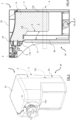
- Figure 1 shows a prior art containing casing for containing liquid foods, which comprises a containing bag intended to operate in combination with a box-shaped body, being placed and contained in the latter, as shown in Figure 2 .
- the bag - which is equipped with a lateral surface, defined by several layers of thin, membrane-structure material having high strength and micrometric thickness which are superposed and monolithically welded to each other - substantially defines a containing casing suitable for supplying, by falling, that is to say under the effect of gravity, a fluid to be dispensed through a suitable tap which can be switched between two states, respectively open and closed, which is located in the lower part of the box-shaped body.
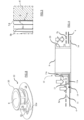
- Figures 3 and 4 respectively show two examples - by way of example only and without limiting the scope of the invention - of a fluid dispenser 1 according to the invention and basically comprising a containing casing labelled 2 as a whole, which has an inner containment cavity 3 for a first fluid 6 to be dispensed, said first fluid 6 being in particular, preferably, a liquid food, selected for example from the families of wines, beers, oils and the like.
- the containment cavity 3 is delimited by a first enclosing wall 4 which: is substantially bag-shaped; is placed in direct contact with the fluid 6 to be dispensed; and is provided with its own membrane-like structure, made in a multilayer form and with micrometric thickness.
- a second wall 5a externally covers, by at least partly surrounding, the first wall 4 which contains the fluid 6 and, in combination with the latter, delimits a closed hollow space 7 interposed between the two walls 4, 5a.
- a second fluid 8 is introduced into the hollow space in such a way that it is forced to interact with the first wall 4, on the outer side of the containment cavity 3, compressing it against the fluid 6 behind it.
- the second fluid 8 causes the subsequent supplying of the fluid 6 forcedly and, as already indicated, from the top zone of the casing 2 as shown in Figures 3 and 4 .
- Figures 3 and 5 show, in particular, that preferably the hollow space 7 is made between two walls 4, 5a which both have micrometric thicknesses and a membrane-like structure.
- the walls 4, 5a may either have stiffnesses which are similar to each other, or different stiffnesses. In the latter case it is preferable that the greater stiffness is offered by the outermost wall 5a, in such a way as to give the containing casing 2 an anisotropic behaviour (and if necessary having self-supporting properties) so as to accentuate the effectiveness of the thrust applied by the wall 4 against the fluid 6 to be dispensed, behind and contained in the containment cavity 3.
- Figures 4 and 5 also show how - in one possible variant of the invention - the hollow space 7 could even be a physical space simply geometrically interposed between the first wall 4 and a second wall 5b, which is stiffer and thicker, identifiable as a perimeter wall of a hollow containing body 10 with relative lid 25, which is part of the containing casing 2 and which houses inside it, surrounding it and if necessary in a sealed way, a bag defined by the first wall 4 and by the relative inner cavity 3 intended to receive the first fluid 6 to be dispensed.
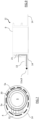
- Figures 6 , 7 and 8 show that the dispenser 1 also comprises a flange 12 which is interconnected with a pair of walls 4 and 5a which both have a membrane-like structure and which are superposed on each other ( Figure 6 , on the right.
- the flange 12 as is clearly shown in Figure 8 , has a flat plate 14 shaped like an annulus, which supports cantilever-style a tubular collar 20, which at its end distal from the plate 14 terminates with the supplying outlet 9.
- the collar 20 is provided with a basically prismatic projection 13, having smoothed edges, which projects radially from the collar 20 and which projects away from it, partly covering a corresponding underlying local surface of the plate 14.
- the projection 13 has, facing the plate 14, a groove with substantially prismatic shape.
- Figures 6 and 7 show that the operative interconnection between the projection 13 (which communicates with the environment outside the containing casing 2) and the hollow space 7 (however it is made, and placed adjacent to the first wall 4) is obtained by means of a local and special connection between the membrane-like walls 4 and 5a and the projection 13.
- the positioning of the pressing means 15, which in the example in Figure 4 are integrated in the structure of the dispenser 1, is particularly useful and advantageous in a portable construction solution of the dispenser 1.
- the pressing means 15 could even be positioned outside the casing 2 and if necessary could even be independent of it, it being enough for them to be able to send pressurised air, for example through the inlet hole 21 of the duct 11.
- Sensor means 16 for detecting a threshold value which is the limit of the pressure of the second fluid 8 contained in the hollow space 7, relative to which the pressing means 15 must be activated/deactivated, may consist for example of a pressure regulator which, suitably integrated in the pressing means 15, acts as an automatic start/stop switch for the pressing means 15.
- the invention achieves the proposed aims by allowing the simple, inexpensive and highly effective achievement of a high degree of expulsion of the air from the containment chamber 3: which results in optimum protection against atmospheric oxidation for the fluids contained. That is particularly advantageous for many fluid foods in which oxidation may cause significant modification of the organoleptic properties of the substance, as is the case for example with wine, beer, oil, cocktails, fruit juices and the like.
- the invention also brings further advantages, including not requiring any external action in order to completely empty the contents of its containment cavity 3.
- the dispenser 1 solution according to this invention and which, as is clearly illustrated in Figures 3 and 4 , has the supplying tap positioned at the top, allows total emptying of the containment chamber 3 without requiring any tilting of the containing casing 2.
- the invention advantageously is also suitable for further useful developments, for example the integration of refrigerating means 17 for the fluid 6 to be dispensed, symbolically represented in Figure 4 which, for example, could also be particularly useful for allowing supplying of the fluid food 6 at optimum preservation and serving temperature conditions, it being known that this is generally required for wines and in particular white wines.
- the invention described above is susceptible of evident industrial application. It may also be modified and adapted in several ways without thereby departing from the scope of the following claims.
Landscapes
- Containers And Packaging Bodies Having A Special Means To Remove Contents (AREA)
- Devices For Dispensing Beverages (AREA)
- Nozzles (AREA)
- Feeding, Discharge, Calcimining, Fusing, And Gas-Generation Devices (AREA)
- Details Of Rigid Or Semi-Rigid Containers (AREA)
Applications Claiming Priority (2)
| Application Number | Priority Date | Filing Date | Title |
|---|---|---|---|
| IT201800002421A IT201800002421A1 (it) | 2018-02-05 | 2018-02-05 | Dispensatore di fluidi |
| PCT/IT2019/050026 WO2019150409A1 (en) | 2018-02-05 | 2019-02-01 | Fluid dispenser |
Publications (3)
| Publication Number | Publication Date |
|---|---|
| EP3749607A1 EP3749607A1 (en) | 2020-12-16 |
| EP3749607C0 EP3749607C0 (en) | 2025-01-08 |
| EP3749607B1 true EP3749607B1 (en) | 2025-01-08 |
Family
ID=62044901
Family Applications (1)
| Application Number | Title | Priority Date | Filing Date |
|---|---|---|---|
| EP19707890.0A Active EP3749607B1 (en) | 2018-02-05 | 2019-02-01 | Fluid dispenser |
Country Status (13)
| Country | Link |
|---|---|
| US (1) | US11535505B2 (enExample) |
| EP (1) | EP3749607B1 (enExample) |
| JP (1) | JP7270266B2 (enExample) |
| KR (1) | KR20200116157A (enExample) |
| CN (1) | CN111670157B (enExample) |
| AU (1) | AU2019213858B2 (enExample) |
| BR (1) | BR112020015924A2 (enExample) |
| CL (1) | CL2020002035A1 (enExample) |
| IT (1) | IT201800002421A1 (enExample) |
| MY (1) | MY202455A (enExample) |
| RU (1) | RU2020128725A (enExample) |
| WO (1) | WO2019150409A1 (enExample) |
| ZA (1) | ZA202004869B (enExample) |
Families Citing this family (1)
| Publication number | Priority date | Publication date | Assignee | Title |
|---|---|---|---|---|
| IT201800002421A1 (it) * | 2018-02-05 | 2019-08-05 | Beexlab S R L | Dispensatore di fluidi |
Citations (2)
| Publication number | Priority date | Publication date | Assignee | Title |
|---|---|---|---|---|
| US8844774B2 (en) * | 2007-08-28 | 2014-09-30 | Entegris, Inc. | Pressurized system for dispensing fluids |
| WO2016131113A2 (en) * | 2015-02-10 | 2016-08-25 | Cardiff Group, Naamloze Vennootschap | Barrel for co2-containing drinks and use thereof |
Family Cites Families (22)
| Publication number | Priority date | Publication date | Assignee | Title |
|---|---|---|---|---|
| US4909289A (en) * | 1987-07-02 | 1990-03-20 | Jopado Baderi | Filling and dispensing valve with drop-away valve member |
| GB9002556D0 (en) * | 1990-02-06 | 1990-04-04 | Ag Patents Ltd | Beverage containers and methods of dispensing beverages |
| US5251787A (en) * | 1992-03-09 | 1993-10-12 | Simson Anton K | Pressurized container dispenser |
| CU23060A3 (es) | 1997-09-04 | 2005-06-24 | Heineken Tech Services | Unidad para almacenar y para despachar cerveza y otras bebidas carbonatadas |
| NL1009654C2 (nl) * | 1998-07-15 | 2000-01-19 | Heineken Tech Services | Klepsamenstel voor een drankcontainer, container voor drank en werkwijze voor het vullen en legen van een drankcontainer. |
| NL1015368C2 (nl) * | 2000-05-31 | 2001-12-12 | Heineken Tech Services | Drankafgiftesamenstel alsmede houder voor drank, in het bijzonder koolzuurhoudende drank, en drankafgifteleiding voor toepassing in een dergelijk samenstel. |
| JP2002225990A (ja) * | 2001-02-01 | 2002-08-14 | Zojirushi Corp | 飲料注出装置 |
| ES2556644T3 (es) | 2002-11-29 | 2016-01-19 | Anheuser-Busch Inbev S.A. | Sistema de suministro de cerveza con un depósito de presión de gas |
| GB0227938D0 (en) * | 2002-11-29 | 2003-01-08 | Interbrew Sa | Interlocking collar for securing alcohol containing bag to keg container |
| JP3914560B1 (ja) * | 2006-01-31 | 2007-05-16 | 東京応化工業株式会社 | 流体容器用の継手 |
| ITRN20060041A1 (it) * | 2006-06-23 | 2007-12-24 | Celli Spa | Dispositivo di spillatura e dispositivo di erogazione comprendente tale dispositivo di spillatura |
| US7896199B2 (en) * | 2007-05-01 | 2011-03-01 | Daniel Steven Kaczmarek | Portable liquid-dispensing bag |
| JP2011528619A (ja) * | 2008-07-21 | 2011-11-24 | スリーエム イノベイティブ プロパティズ カンパニー | 流体の流れに添加剤を分散するための装置 |
| EP2165968A1 (en) * | 2008-09-19 | 2010-03-24 | InBev S.A. | Bag-in-container with prepressurized space between inner bag and outer container |
| NL2003132C2 (en) * | 2009-07-03 | 2011-01-04 | Heineken Supply Chain Bv | Container, preform assembly and method and apparatus for forming containers. |
| EP2336077A1 (en) * | 2009-12-18 | 2011-06-22 | Anheuser-Busch InBev S.A. | Beverage dispensing apparatus comprising an integrated pressure reducing channel |
| US8763857B2 (en) * | 2010-10-12 | 2014-07-01 | Boxxle, Llc | Liquid dispensing systems |
| NL2009234C2 (en) * | 2012-07-26 | 2014-02-06 | Heineken Supply Chain Bv | Tapping assembly and connecting device, as well as a container and method for beverage dispensing. |
| PT3046866T (pt) * | 2013-09-20 | 2017-11-06 | Carlsberg Breweries As | Método de calibração para um sistema de distribuição de bebida, e um sistema de distribuição de bebida que utiliza o método de calibração |
| CN206298338U (zh) * | 2016-08-31 | 2017-07-04 | 邱迪林 | 一种酒矛 |
| CN106698306B (zh) | 2017-01-13 | 2018-10-30 | 尤赛飞 | 一种酒矛 |
| IT201800002421A1 (it) * | 2018-02-05 | 2019-08-05 | Beexlab S R L | Dispensatore di fluidi |
-
2018
- 2018-02-05 IT IT201800002421A patent/IT201800002421A1/it unknown
-
2019
- 2019-02-01 MY MYPI2020003790A patent/MY202455A/en unknown
- 2019-02-01 BR BR112020015924-7A patent/BR112020015924A2/pt not_active Application Discontinuation
- 2019-02-01 RU RU2020128725A patent/RU2020128725A/ru unknown
- 2019-02-01 WO PCT/IT2019/050026 patent/WO2019150409A1/en not_active Ceased
- 2019-02-01 AU AU2019213858A patent/AU2019213858B2/en active Active
- 2019-02-01 US US16/962,894 patent/US11535505B2/en active Active
- 2019-02-01 EP EP19707890.0A patent/EP3749607B1/en active Active
- 2019-02-01 CN CN201980011070.8A patent/CN111670157B/zh active Active
- 2019-02-01 KR KR1020207025720A patent/KR20200116157A/ko not_active Ceased
- 2019-02-01 JP JP2020563849A patent/JP7270266B2/ja active Active
-
2020
- 2020-08-05 CL CL2020002035A patent/CL2020002035A1/es unknown
- 2020-08-05 ZA ZA2020/04869A patent/ZA202004869B/en unknown
Patent Citations (2)
| Publication number | Priority date | Publication date | Assignee | Title |
|---|---|---|---|---|
| US8844774B2 (en) * | 2007-08-28 | 2014-09-30 | Entegris, Inc. | Pressurized system for dispensing fluids |
| WO2016131113A2 (en) * | 2015-02-10 | 2016-08-25 | Cardiff Group, Naamloze Vennootschap | Barrel for co2-containing drinks and use thereof |
Also Published As
| Publication number | Publication date |
|---|---|
| CN111670157B (zh) | 2022-08-30 |
| AU2019213858B2 (en) | 2023-04-13 |
| US11535505B2 (en) | 2022-12-27 |
| US20210047167A1 (en) | 2021-02-18 |
| NZ766943A (en) | 2024-08-30 |
| WO2019150409A1 (en) | 2019-08-08 |
| CA3090361A1 (en) | 2019-08-08 |
| AU2019213858A1 (en) | 2020-08-27 |
| CL2020002035A1 (es) | 2021-01-29 |
| RU2020128725A (ru) | 2022-03-09 |
| IT201800002421A1 (it) | 2019-08-05 |
| ZA202004869B (en) | 2021-08-25 |
| EP3749607C0 (en) | 2025-01-08 |
| JP7270266B2 (ja) | 2023-05-10 |
| BR112020015924A2 (pt) | 2021-03-30 |
| JP2021512828A (ja) | 2021-05-20 |
| CN111670157A (zh) | 2020-09-15 |
| EP3749607A1 (en) | 2020-12-16 |
| MY202455A (en) | 2024-04-30 |
| KR20200116157A (ko) | 2020-10-08 |
Similar Documents
| Publication | Publication Date | Title |
|---|---|---|
| US9914631B2 (en) | Container for preserving liquid contents | |
| AU753406B2 (en) | Dispenser system | |
| CN104670706B (zh) | 用于存放液态食品的容器 | |
| CN110603199B (zh) | 用于真空储存食品的容器、盖、包括容器和盖的组件以及用于真空包装食品的系统 | |
| US9423041B2 (en) | Dispensing machine valve and method | |
| US20170158485A1 (en) | Spill prevention for interchangeable liquid containers | |
| WO2003016163A1 (en) | Container with discharge flow velocity mechanism | |
| EP3749607B1 (en) | Fluid dispenser | |
| US20170313567A1 (en) | Beverage container assembly for holding a beverage | |
| CA3090361C (en) | Fluid dispenser | |
| EP2231505B1 (en) | An adapter set for use in combination with a collapsible beverage container | |
| JP2021512828A5 (enExample) | ||
| US11066288B2 (en) | Systems and methods for dispensing a beverage stored in a collapsible beverage container | |
| CZ35438U1 (cs) | Soudek s vyměnitelnou vložkou pro potravinářské tekutiny | |
| EP0808286A1 (en) | Bag for containing flowable material | |
| JPS5850091A (ja) | 飲料自動販売機 | |
| IL119934A (en) | Apparatus for quick evacuating and closing lidded jars and vessels containing foodstuff and other products | |
| CZ15475U1 (cs) | Obal na tekutiny, zejména nápoje | |
| HK1207846B (en) | A container for storing a liquid foodstuff | |
| ITTV940003U1 (it) | Contenitore per bevande in pressione | |
| ES2254036A1 (es) | "conjunto de envase para productos alimenticios apto para ser cerrado al vacio hermeticamente". |
Legal Events
| Date | Code | Title | Description |
|---|---|---|---|
| STAA | Information on the status of an ep patent application or granted ep patent |
Free format text: STATUS: UNKNOWN |
|
| STAA | Information on the status of an ep patent application or granted ep patent |
Free format text: STATUS: THE INTERNATIONAL PUBLICATION HAS BEEN MADE |
|
| PUAI | Public reference made under article 153(3) epc to a published international application that has entered the european phase |
Free format text: ORIGINAL CODE: 0009012 |
|
| STAA | Information on the status of an ep patent application or granted ep patent |
Free format text: STATUS: REQUEST FOR EXAMINATION WAS MADE |
|
| 17P | Request for examination filed |
Effective date: 20200824 |
|
| AK | Designated contracting states |
Kind code of ref document: A1 Designated state(s): AL AT BE BG CH CY CZ DE DK EE ES FI FR GB GR HR HU IE IS IT LI LT LU LV MC MK MT NL NO PL PT RO RS SE SI SK SM TR |
|
| AX | Request for extension of the european patent |
Extension state: BA ME |
|
| REG | Reference to a national code |
Ref country code: HK Ref legal event code: DE Ref document number: 40033345 Country of ref document: HK |
|
| DAV | Request for validation of the european patent (deleted) | ||
| DAX | Request for extension of the european patent (deleted) | ||
| STAA | Information on the status of an ep patent application or granted ep patent |
Free format text: STATUS: EXAMINATION IS IN PROGRESS |
|
| 17Q | First examination report despatched |
Effective date: 20240207 |
|
| GRAP | Despatch of communication of intention to grant a patent |
Free format text: ORIGINAL CODE: EPIDOSNIGR1 |
|
| STAA | Information on the status of an ep patent application or granted ep patent |
Free format text: STATUS: GRANT OF PATENT IS INTENDED |
|
| INTG | Intention to grant announced |
Effective date: 20240816 |
|
| GRAS | Grant fee paid |
Free format text: ORIGINAL CODE: EPIDOSNIGR3 |
|
| GRAA | (expected) grant |
Free format text: ORIGINAL CODE: 0009210 |
|
| STAA | Information on the status of an ep patent application or granted ep patent |
Free format text: STATUS: THE PATENT HAS BEEN GRANTED |
|
| AK | Designated contracting states |
Kind code of ref document: B1 Designated state(s): AL AT BE BG CH CY CZ DE DK EE ES FI FR GB GR HR HU IE IS IT LI LT LU LV MC MK MT NL NO PL PT RO RS SE SI SK SM TR |
|
| RAP3 | Party data changed (applicant data changed or rights of an application transferred) |
Owner name: BEEXLAB S.R.L. |
|
| REG | Reference to a national code |
Ref country code: GB Ref legal event code: FG4D |
|
| REG | Reference to a national code |
Ref country code: CH Ref legal event code: EP |
|
| REG | Reference to a national code |
Ref country code: DE Ref legal event code: R096 Ref document number: 602019064567 Country of ref document: DE |
|
| REG | Reference to a national code |
Ref country code: IE Ref legal event code: FG4D |
|
| U01 | Request for unitary effect filed |
Effective date: 20250128 |
|
| U07 | Unitary effect registered |
Designated state(s): AT BE BG DE DK EE FI FR IT LT LU LV MT NL PT RO SE SI Effective date: 20250203 |
|
| U20 | Renewal fee for the european patent with unitary effect paid |
Year of fee payment: 7 Effective date: 20250225 |
|
| PG25 | Lapsed in a contracting state [announced via postgrant information from national office to epo] |
Ref country code: RS Free format text: LAPSE BECAUSE OF FAILURE TO SUBMIT A TRANSLATION OF THE DESCRIPTION OR TO PAY THE FEE WITHIN THE PRESCRIBED TIME-LIMIT Effective date: 20250408 |
|
| PG25 | Lapsed in a contracting state [announced via postgrant information from national office to epo] |
Ref country code: PL Free format text: LAPSE BECAUSE OF FAILURE TO SUBMIT A TRANSLATION OF THE DESCRIPTION OR TO PAY THE FEE WITHIN THE PRESCRIBED TIME-LIMIT Effective date: 20250108 |
|
| PG25 | Lapsed in a contracting state [announced via postgrant information from national office to epo] |
Ref country code: ES Free format text: LAPSE BECAUSE OF FAILURE TO SUBMIT A TRANSLATION OF THE DESCRIPTION OR TO PAY THE FEE WITHIN THE PRESCRIBED TIME-LIMIT Effective date: 20250108 |
|
| PG25 | Lapsed in a contracting state [announced via postgrant information from national office to epo] |
Ref country code: NO Free format text: LAPSE BECAUSE OF FAILURE TO SUBMIT A TRANSLATION OF THE DESCRIPTION OR TO PAY THE FEE WITHIN THE PRESCRIBED TIME-LIMIT Effective date: 20250408 Ref country code: IS Free format text: LAPSE BECAUSE OF FAILURE TO SUBMIT A TRANSLATION OF THE DESCRIPTION OR TO PAY THE FEE WITHIN THE PRESCRIBED TIME-LIMIT Effective date: 20250508 |
|
| PG25 | Lapsed in a contracting state [announced via postgrant information from national office to epo] |
Ref country code: HR Free format text: LAPSE BECAUSE OF FAILURE TO SUBMIT A TRANSLATION OF THE DESCRIPTION OR TO PAY THE FEE WITHIN THE PRESCRIBED TIME-LIMIT Effective date: 20250108 |
|
| PG25 | Lapsed in a contracting state [announced via postgrant information from national office to epo] |
Ref country code: GR Free format text: LAPSE BECAUSE OF FAILURE TO SUBMIT A TRANSLATION OF THE DESCRIPTION OR TO PAY THE FEE WITHIN THE PRESCRIBED TIME-LIMIT Effective date: 20250409 |
|
| REG | Reference to a national code |
Ref country code: CH Ref legal event code: PL |
|
| PG25 | Lapsed in a contracting state [announced via postgrant information from national office to epo] |
Ref country code: SM Free format text: LAPSE BECAUSE OF FAILURE TO SUBMIT A TRANSLATION OF THE DESCRIPTION OR TO PAY THE FEE WITHIN THE PRESCRIBED TIME-LIMIT Effective date: 20250108 |
|
| PG25 | Lapsed in a contracting state [announced via postgrant information from national office to epo] |
Ref country code: MC Free format text: LAPSE BECAUSE OF FAILURE TO SUBMIT A TRANSLATION OF THE DESCRIPTION OR TO PAY THE FEE WITHIN THE PRESCRIBED TIME-LIMIT Effective date: 20250108 |
|
| PG25 | Lapsed in a contracting state [announced via postgrant information from national office to epo] |
Ref country code: CH Free format text: LAPSE BECAUSE OF NON-PAYMENT OF DUE FEES Effective date: 20250228 |
|
| PG25 | Lapsed in a contracting state [announced via postgrant information from national office to epo] |
Ref country code: CZ Free format text: LAPSE BECAUSE OF FAILURE TO SUBMIT A TRANSLATION OF THE DESCRIPTION OR TO PAY THE FEE WITHIN THE PRESCRIBED TIME-LIMIT Effective date: 20250108 |
|
| PG25 | Lapsed in a contracting state [announced via postgrant information from national office to epo] |
Ref country code: SK Free format text: LAPSE BECAUSE OF FAILURE TO SUBMIT A TRANSLATION OF THE DESCRIPTION OR TO PAY THE FEE WITHIN THE PRESCRIBED TIME-LIMIT Effective date: 20250108 |
|
| PLBE | No opposition filed within time limit |
Free format text: ORIGINAL CODE: 0009261 |
|
| STAA | Information on the status of an ep patent application or granted ep patent |
Free format text: STATUS: NO OPPOSITION FILED WITHIN TIME LIMIT |
|
| 26N | No opposition filed |
Effective date: 20251009 |
|
| GBPC | Gb: european patent ceased through non-payment of renewal fee |
Effective date: 20250408 |
|
| PG25 | Lapsed in a contracting state [announced via postgrant information from national office to epo] |
Ref country code: GB Free format text: LAPSE BECAUSE OF NON-PAYMENT OF DUE FEES Effective date: 20250408 |
|
| PG25 | Lapsed in a contracting state [announced via postgrant information from national office to epo] |
Ref country code: IE Free format text: LAPSE BECAUSE OF NON-PAYMENT OF DUE FEES Effective date: 20250201 |
|
| U20 | Renewal fee for the european patent with unitary effect paid |
Year of fee payment: 8 Effective date: 20260225 |