EP3749539B1 - Ensemble d'alimentation en carburant ou en produit de depollution d'un vehicule automobile - Google Patents
Ensemble d'alimentation en carburant ou en produit de depollution d'un vehicule automobile Download PDFInfo
- Publication number
- EP3749539B1 EP3749539B1 EP19708139.1A EP19708139A EP3749539B1 EP 3749539 B1 EP3749539 B1 EP 3749539B1 EP 19708139 A EP19708139 A EP 19708139A EP 3749539 B1 EP3749539 B1 EP 3749539B1
- Authority
- EP
- European Patent Office
- Prior art keywords
- head
- pipe
- pipe head
- collar
- assembly
- Prior art date
- Legal status (The legal status is an assumption and is not a legal conclusion. Google has not performed a legal analysis and makes no representation as to the accuracy of the status listed.)
- Active
Links
Images


Classifications
-
- B—PERFORMING OPERATIONS; TRANSPORTING
- B60—VEHICLES IN GENERAL
- B60K—ARRANGEMENT OR MOUNTING OF PROPULSION UNITS OR OF TRANSMISSIONS IN VEHICLES; ARRANGEMENT OR MOUNTING OF PLURAL DIVERSE PRIME-MOVERS IN VEHICLES; AUXILIARY DRIVES FOR VEHICLES; INSTRUMENTATION OR DASHBOARDS FOR VEHICLES; ARRANGEMENTS IN CONNECTION WITH COOLING, AIR INTAKE, GAS EXHAUST OR FUEL SUPPLY OF PROPULSION UNITS IN VEHICLES
- B60K15/00—Arrangement in connection with fuel supply of combustion engines or other fuel consuming energy converters, e.g. fuel cells; Mounting or construction of fuel tanks
- B60K15/03—Fuel tanks
- B60K15/04—Tank inlets
-
- B—PERFORMING OPERATIONS; TRANSPORTING
- B60—VEHICLES IN GENERAL
- B60K—ARRANGEMENT OR MOUNTING OF PROPULSION UNITS OR OF TRANSMISSIONS IN VEHICLES; ARRANGEMENT OR MOUNTING OF PLURAL DIVERSE PRIME-MOVERS IN VEHICLES; AUXILIARY DRIVES FOR VEHICLES; INSTRUMENTATION OR DASHBOARDS FOR VEHICLES; ARRANGEMENTS IN CONNECTION WITH COOLING, AIR INTAKE, GAS EXHAUST OR FUEL SUPPLY OF PROPULSION UNITS IN VEHICLES
- B60K15/00—Arrangement in connection with fuel supply of combustion engines or other fuel consuming energy converters, e.g. fuel cells; Mounting or construction of fuel tanks
- B60K15/03—Fuel tanks
- B60K15/04—Tank inlets
- B60K15/05—Inlet covers
-
- B—PERFORMING OPERATIONS; TRANSPORTING
- B60—VEHICLES IN GENERAL
- B60K—ARRANGEMENT OR MOUNTING OF PROPULSION UNITS OR OF TRANSMISSIONS IN VEHICLES; ARRANGEMENT OR MOUNTING OF PLURAL DIVERSE PRIME-MOVERS IN VEHICLES; AUXILIARY DRIVES FOR VEHICLES; INSTRUMENTATION OR DASHBOARDS FOR VEHICLES; ARRANGEMENTS IN CONNECTION WITH COOLING, AIR INTAKE, GAS EXHAUST OR FUEL SUPPLY OF PROPULSION UNITS IN VEHICLES
- B60K15/00—Arrangement in connection with fuel supply of combustion engines or other fuel consuming energy converters, e.g. fuel cells; Mounting or construction of fuel tanks
- B60K15/03—Fuel tanks
- B60K15/04—Tank inlets
- B60K2015/0458—Details of the tank inlet
-
- B—PERFORMING OPERATIONS; TRANSPORTING
- B60—VEHICLES IN GENERAL
- B60K—ARRANGEMENT OR MOUNTING OF PROPULSION UNITS OR OF TRANSMISSIONS IN VEHICLES; ARRANGEMENT OR MOUNTING OF PLURAL DIVERSE PRIME-MOVERS IN VEHICLES; AUXILIARY DRIVES FOR VEHICLES; INSTRUMENTATION OR DASHBOARDS FOR VEHICLES; ARRANGEMENTS IN CONNECTION WITH COOLING, AIR INTAKE, GAS EXHAUST OR FUEL SUPPLY OF PROPULSION UNITS IN VEHICLES
- B60K15/00—Arrangement in connection with fuel supply of combustion engines or other fuel consuming energy converters, e.g. fuel cells; Mounting or construction of fuel tanks
- B60K15/03—Fuel tanks
- B60K15/04—Tank inlets
- B60K15/05—Inlet covers
- B60K2015/0553—Details concerning the inlet box or bowl in the vehicle car body panel
Definitions
- the present invention relates to an assembly for supplying fuel or pollution control product to a motor vehicle of the type comprising a filler hatch housing and a tank pipe.
- a fuel or depollution liquid supply system for a motor vehicle comprises a liquid tank, a fuel filler pipe which starts from the tank and ends close to an opening provided in an external body panel.
- a fill hatch housing disposed in the panel opening is adapted to receive a tubing head mounted on the free end of the tubing.
- the head of the pipe has defined dimensions to which the hatch box adapts to allow tight and visually aesthetic docking. These two pieces have complementary shapes when designed together.
- the invention thus makes it possible, in the event of modification of the configuration of one of the parts among the hatch casing or the pipe head, to avoid having to adapt the other part accordingly. Indeed, even if these two parts no longer have corresponding shapes, the invention makes it possible, thanks to the presence of the flange, to maintain an aesthetic and sealed assembly.
- retaining lugs are provided on an internal periphery of the first tubular portion.
- the second portion is located in an extension of an axial end of the first tubular portion.
- the second portion is intended to bear against a shoulder of the head of the pipe.
- the collar is attached relative to the head of the pipe.
- the pipe head comprises a fixing lug on a structural element of the motor vehicle.
- the pipe head is made of a metallic material.
- the collar is made of a plastic material.
- the invention also relates to a motor vehicle comprising a supply assembly for fuel or pollution control product as defined above.
- the figure 1 is a perspective view of a manifold and a manifold head for receiving a flange according to the present invention
- the figure 2 is a perspective view of a collar according to the present invention.
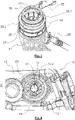
- the picture 3 is a perspective view of the assembly according to the invention comprising a flange mounted around the head of the tubing of the figure 1 ;
- the figure 4 is a front view of a trap box in which the head of the pipe and the associated flange according to the invention are mounted;
- the figure 5 is a perspective view, from inside the vehicle, of a hatch box in which is mounted the head of the pipe and the associated flange according to the invention.
- FIG. 10 With reference to the drawings of figure 4 and 5 , there is shown an assembly 10 for supplying fuel to a motor vehicle according to the present invention.
- the assembly 10 includes a fuel filler flap housing 12 mounted on the vehicle body.
- the hatch box 12 has a main body 12.1, which is made of rigid plastic material, and a central bottom part 12.2, for example of annular shape, which is made of flexible material so as to facilitate the passage of a head tubing 14.
- the tubing head 14 is thus inserted inside an opening 15 made in the hatch housing 12 and more precisely in the bottom 12.2 made of flexible material which is intended to match the shape of the tubing head 14.
- This hollow tubing head 14 has a through hole 17, visible on the figure 1 , 3, and 4 , intended to receive a fuel filler nozzle (not shown).
- the through hole 17 leads to a pipe 21 described in more detail below.
- the tubing head 14 can be closed by a plug (not shown) capable of cooperating with a locking ramp 19, for example of the quarter-turn type, provided in a internal face of the pipe head 14.
- the ramp 19 could be replaced by a cap screwing thread.
- a pipe 21, for example of cylindrical shape, is connected by one of its ends to the pipe head 14 and by its other end to a fuel tank.
- the head of tubing 14 is fixed by a snap device on the free end of the tubing 21.
- a degassing pipette 22 opening on the one hand into the reservoir and on the other hand into the tubing 21 allows the fuel vapors to be evacuated when filling the tank.
- the latter comprises a fixing lug 23 on a structural element of the body of the vehicle.
- the shape and dimensions of the mounting lug 23 are adapted according to the configuration of the vehicle at the level of the hatch housing 12 which may vary from one model to another.
- the pipe head 14 being advantageously made of a metallic material to comply with the new anti-pollution standards, the fixing lug 23, also made of metal, can provide electrical conductivity with the body to evacuate static electricity. This avoids, for safety reasons, the creation of sparks in an environment with a high presence of fuel.
- an attached collar 25 closes off a space E between an outer periphery of said pipe head 14 and an edge of the hatch housing 12 delimiting the passage opening of said pipe head 14.
- the obturation collar 25 clearly visible on the figure 2 comprises a first portion 25.1 of tubular shape intended to be mounted around the head of the pipe 14, and a second portion 25.2 having an annular shape of radial orientation with respect to an axis X of the first tubular portion 25.1.
- the second portion 25.2 thus extends in a radial plane relative to the axis X.
- This second portion 25.2 has a radial length greater than its axial thickness.
- the second portion 25.2 is located in the extension of the axial end of the first tubular portion 25.1 farthest from the side of the hole 17 opening outwards.
- the second portion 25.2 is intended to bear against a shoulder 27 of the manifold head 14, as shown in the figure 1 and 3 .
- This shoulder 27 is formed by a difference in diameter of the outer periphery of the pipe head 14.
- the first tubular portion 25.1 has an internal diameter corresponding to the external diameter of the end portion of the pipe head 14 delimited axially by the shoulder 27.
- retaining lugs 29 are provided on the internal periphery of the first tubular portion 25.1, as is visible on the figure 2 .
- the lugs 29 project radially towards the inside of the collar 25.
- the holding force can be adapted according to the size of the lugs 29 and their number. In this case, three lugs 29 spaced apart angularly from one another in a regular manner are used. However, the number and arrangement of the lugs 29 may vary depending on the application.
- the collar 25 is preferably made of a plastic material. It may be obtained for example by molding or by injection. It will thus be easy to make the shapes of the radial annular portion 25.2 and the lugs 29.
- the collar 25 could be fixed by gluing to the head of the pipe 14 or any other suitable fixing method.
- the collar 25 can be made in one piece with respect to the head of the pipe 14 by being molded over with the head of the pipe 14 which would then be bi-material.
- the dimensions of the collar 25, in particular its axial height H and its largest diameter D corresponding to the external diameter of the radial annular portion 25.2 (cf. picture 2 ), are adapted according to the application and in particular according to the dimensions of the pipe head 14 and of the space E to be filled between the pipe head 14 and the opening 15 of the hatch housing 12.
- the assembly 10 provides a supply of depollution product to the motor vehicle.
- the depollution product stored in a corresponding tank, may take a liquid or powder form.
Landscapes
- Engineering & Computer Science (AREA)
- Life Sciences & Earth Sciences (AREA)
- Sustainable Development (AREA)
- Sustainable Energy (AREA)
- Chemical & Material Sciences (AREA)
- Combustion & Propulsion (AREA)
- Transportation (AREA)
- Mechanical Engineering (AREA)
- Cooling, Air Intake And Gas Exhaust, And Fuel Tank Arrangements In Propulsion Units (AREA)
Description
- La présente invention porte sur un ensemble d'alimentation en carburant ou en produit de dépollution d'un véhicule automobile du type comprenant un boîtier de trappe de remplissage et une tubulure de réservoir.
- De façon connue en soi, un système d'alimentation en carburant ou en liquide de dépollution d'un véhicule automobile comprend un réservoir de liquide, une tubulure de remplissage de carburant qui part du réservoir et se termine à proximité d'une ouverture prévue dans un panneau externe de la carrosserie. Un boîtier de trappe de remplissage disposé dans l'ouverture du panneau est conçu pour recevoir une tête de tubulure montée sur l'extrémité libre de la tubulure.
- La tête de tubulure présente des dimensions définies auquel s'adapte le boîtier de trappe pour permettre un accostage étanche et visuellement esthétique. Ces deux pièces présentent des formes complémentaires lorsqu'elles sont conçues conjointement.
- Toutefois, dans le cas où il devient nécessaire de modifier la configuration de la tête de tubulure, cela a une influence sur l'assemblage final. Ainsi, il peut apparaître un jeu périphérique autour de la tête de tubulure dans le cas où cette dernière présente un diamètre réduit. Cela implique un nouveau développement du boîtier de trappe pour combler le jeu périphérique. Il existe un problème analogue si la configuration du boîtier de trappe venait à être modifiée. Or cela est coûteux et génère une diversité de pièces pour les usines terminales de montage des véhicules automobiles.
- Des autres ensembles d'alimentation en carburant ou en produit de dépollution d'un véhicule automobile sont connus des documents
DE 24 18 063 A1 ,KR 2013 0002525 A EP 0 277 294 A2 . - L'invention vise à remédier efficacement à cet inconvénient en proposant un ensemble d'alimentation en carburant ou en produit de dépollution d'un véhicule automobile selon la revendication 1. L'ensemble comporte:
- un boîtier de trappe,
- une tête de tubulure destinée à s'insérer à l'intérieur d'une ouverture ménagée dans le boîtier de trappe,
- une tubulure connectée par une de ses extrémités à la tête de tubulure et par son autre extrémité à un réservoir de carburant ou de produit de dépollution,
- L'invention permet ainsi, en cas de modification de la configuration d'une des pièces parmi le boîtier de trappe ou la tête de tubulure, d'éviter d'avoir à adapter l'autre pièce en conséquence. En effet, même si ces deux pièces ne présentent plus des formes correspondantes, l'invention permet, grâce à la présence de la collerette, de conserver un ensemble esthétique et étanche.
- Selon l'invention, la collerette comporte:
- une première portion de forme tubulaire destinée à être montée autour de la tête de tubulure, et
- une deuxième portion ayant une forme annulaire d'orientation radiale par rapport à un axe de la première portion tubulaire.
- Selon l'invention, des ergots de maintien sont ménagés sur une périphérie interne de la première portion tubulaire.
- Selon une réalisation, la deuxième portion est située dans un prolongement d'une extrémité axiale de la première portion tubulaire.
- Selon une réalisation, la deuxième portion est destinée à venir en appui contre un épaulement de la tête de tubulure.
- Selon une réalisation, la collerette est rapportée par rapport à la tête de tubulure.
- Selon une réalisation, la tête de tubulure comporte une patte de fixation sur un élément structurel du véhicule automobile.
- Selon une réalisation, la tête de tubulure est réalisée dans un matériau métallique.
- Selon une réalisation, la collerette est réalisée dans un matériau plastique.
- L'invention a également pour objet un véhicule automobile comprenant un ensemble d'alimentation en carburant ou en produit de dépollution tel que précédemment défini.
- L'invention sera mieux comprise à la lecture de la description qui suit et à l'examen des figures qui l'accompagnent. Ces figures ne sont données qu'à titre illustratif mais nullement limitatif de l'invention.
- La
figure 1 est une vue en perspective d'une tubulure et d'une tête de tubulure destinée à recevoir une collerette selon la présente invention; - La
figure 2 est une vue en perspective d'une collerette selon la présente invention; - La
figure 3 est une vue en perspective de l'ensemble selon l'invention comportant une collerette montée autour de la tête de tubulure de lafigure 1 ; - La
figure 4 est une vue de face d'un boîtier de trappe dans lequel sont montées la tête de tubulure et la collerette associée selon l'invention; - La
figure 5 est une vue en perspective, depuis l'intérieur du véhicule, d'un boîtier de trappe dans lequel est monté la tête de tubulure et la collerette associée selon l'invention. - Les éléments identiques similaires ou analogues conservent la même référence d'une figure à l'autre.
- En référence aux dessins des
figures 4 et5 , on a représenté un ensemble 10 d'alimentation en carburant d'un véhicule automobile selon la présente invention. - L'ensemble 10 comprend un boîtier de trappe 12 de remplissage de carburant monté sur la caisse du véhicule. Le boîtier de trappe 12 présente un corps principal 12.1, qui est réalisé en matière plastique rigide, et une partie centrale 12.2, de fond, par exemple de forme annulaire, qui est réalisée en matière souple de manière à favoriser le passage d'une tête de tubulure 14.
- La tête de tubulure 14 est ainsi insérée à l'intérieur d'une ouverture 15 ménagée dans le boîtier de trappe 12 et plus précisément dans le fond 12.2 en matière souple qui est destiné à épouser la forme de la tête de tubulure 14.
- Cette tête de tubulure 14 creuse comporte un trou traversant 17, visible sur les
figures 1 ,3, et 4 , destiné à recevoir un pistolet de remplissage de carburant (non représenté). Le trou traversant 17 débouche vers une tubulure 21 décrite plus en détails ci-après. La tête de tubulure 14 est obturable par un bouchon (non représenté) apte à coopérer avec une rampe 19 de verrouillage, par exemple de type quart de tour, ménagée dans une face interne de la tête de tubulure 14. En variante, la rampe 19 pourra être remplacée par un filet de vissage du bouchon. - Comme on peut le voir sur les
figures 1 ,3 , et5 , une tubulure 21, par exemple de forme cylindrique, est connectée par une de ses extrémités à la tête de tubulure 14 et par son autre extrémité à un réservoir de carburant. Suivant un exemple de réalisation, la tête de tubulure 14 est fixée par un dispositif d'encliquetage sur l'extrémité libre de la tubulure 21. Une pipette de dégazage 22 débouchant d'une part dans le réservoir et d'autre part dans la tubulure 21 permet d'évacuer les vapeurs de carburant lors du remplissage du réservoir. - Afin d'assurer le maintien en position de la tête de tubulure 14, cette dernière comporte une patte de fixation 23 sur un élément structurel de la caisse du véhicule. La forme et les dimensions de la patte de fixation 23 sont adaptées en fonction de la configuration du véhicule au niveau du boîtier de trappe 12 susceptible de varier d'un modèle à l'autre.
- La tête de tubulure 14 étant avantageusement réalisée dans un matériau métallique pour le respect des nouvelles normes antipollution, la patte de fixation 23 également en métal, pourra assurer une conductivité électrique avec la caisse pour évacuer l'électricité statique. On évite ainsi, pour des questions de sécurité, la création d'étincelles dans un environnement à forte présence de carburant.
- En outre, comme cela est illustré par les
figures 4 et5 , une collerette rapportée 25 assure l'obturation d'un espace E entre une périphérie externe de ladite tête de tubulure 14 et un bord du boîtier de trappe 12 délimitant l'ouverture de passage de ladite tête de tubulure 14. - La collerette d'obturation 25 bien visible sur la
figure 2 comporte une première portion de forme tubulaire 25.1 destinée à être montée autour de la tête de tubulure 14, et une deuxième portion 25.2 ayant une forme annulaire d'orientation radiale par rapport à un axe X de la première portion tubulaire 25.1. La deuxième portion 25.2 s'étend ainsi dans un plan radial par rapport à l'axe X. Cette deuxième portion 25.2 présente une longueur radiale supérieure à son épaisseur axiale. - La deuxième portion 25.2 est située dans le prolongement de l'extrémité axiale de la première portion tubulaire 25.1 la plus éloignée du côté du trou 17 débouchant vers l'extérieur. La deuxième portion 25.2 est destinée à venir en appui contre un épaulement 27 de la tête de tubulure 14, tel que cela est montré sur les
figures 1 et3 . Cet épaulement 27 est formé par une différence de diamètre de la périphérie externe de la tête de tubulure 14. - Avantageusement, la première portion tubulaire 25.1 présente un diamètre interne correspondant au diamètre externe de la portion d'extrémité de la tête de tubulure 14 délimité axialement par l'épaulement 27.
- Afin d'assurer le maintien de la collerette 25 sur la tête de tubulure 14, des ergots de maintien 29 sont ménagés sur la périphérie interne de la première portion tubulaire 25.1, tel que cela est visible sur la
figure 2 . Les ergots 29 font saillie radialement vers l'intérieur de la collerette 25. L'effort de maintien pourra être adapté en fonction de la dimension des ergots 29 et de leur nombre. En l'occurrence, on utilise trois ergots 29 espacés angulairement entre eux de façon régulière. Toutefois, le nombre et la disposition des ergots 29 pourront varier en fonction de l'application. - La collerette 25 est réalisée de préférence dans un matériau plastique. Elle pourra être obtenue par exemple par moulage ou par injection. Il sera ainsi aisé de réaliser les formes de la portion annulaire radiale 25.2 et des ergots 29.
- En variante, la collerette 25 pourra être fixée par collage sur la tête de tubulure 14 ou toute autre méthode de fixation adaptée. En variante, la collerette 25 peut être monobloc par rapport à la tête de tubulure 14 en étant surmoulée avec la tête de tubulure 14 qui serait alors bi-matière.
- Les dimensions de la collerette 25, en particulier sa hauteur axiale H et son plus grand diamètre D correspondant au diamètre externe de la portion annulaire radiale 25.2 (cf.
figure 2 ), sont adaptés en fonction de l'application et notamment en fonction des dimensions de la tête de tubulure 14 et de l'espace E à combler entre la tête de tubulure 14 et l'ouverture 15 du boîtier de trappe 12. - En variante, l'ensemble 10 assure une alimentation en produit de dépollution du véhicule automobile. Le produit de dépollution, stocké dans un réservoir correspondant, pourra prendre une forme liquide ou en poudre.
Claims (8)
- Ensemble (10) d'alimentation en carburant ou en produit de dépollution d'un véhicule automobile comportant:- un boîtier de trappe (12),- une tête de tubulure (14) destinée à s'insérer à l'intérieur d'une ouverture (15) ménagée dans ledit boîtier de trappe (12),- une tubulure (21) connectée par une de ses extrémités à ladite tête de tubulure (14) et par son autre extrémité à un réservoir de carburant ou de produit de dépollution,ledit ensemble (10) comportant en outre une collerette (25) d'obturation d'un espace (E) entre une périphérie externe de ladite tête de tubulure (14) et un bord du boîtier de trappe (12) délimitant l'ouverture (15) de passage de ladite tête de tubulure (14), ladite collerette (25) comportant :- une première portion de forme tubulaire (25.1) destinée à être montée autour de la tête de tubulure (14), et- une deuxième portion (25.2) ayant une forme annulaire d'orientation radiale par rapport à un axe (X) de la première portion tubulaire (25.1), caractérisé en ce que des ergots de maintien (29) sont ménagés sur une périphérie interne de la première portion tubulaire (25.1).
- Ensemble selon la revendication 1, caractérisé en ce que la deuxième portion (25.2) est située dans un prolongement d'une extrémité axiale de la première portion tubulaire (25.1).
- Ensemble selon l'une quelconque des revendications 1 ou 2, caractérisé en ce que la deuxième portion (25.2) est destinée à venir en appui contre un épaulement (27) de la tête de tubulure (14).
- Ensemble selon l'une quelconque des revendications 1 à 3, caractérisé en ce que la collerette (25) est rapportée par rapport à la tête de tubulure (14).
- Ensemble selon l'une quelconque des revendications 1 à 4, caractérisé en ce que la tête de tubulure (14) comporte une patte de fixation (23) sur un élément structurel du véhicule automobile.
- Ensemble selon l'une quelconque des revendications 1 à 5, caractérisé en ce que la tête de tubulure (14) est réalisée dans un matériau métallique.
- Ensemble selon l'une quelconque des revendications 1 à 6, caractérisé en ce que la collerette (25) est réalisée dans un matériau plastique.
- Véhicule automobile caractérisé en ce qu'il comprend un ensemble (10) d'alimentation en carburant ou en produit de dépollution tel que défini selon l'une quelconque des revendications précédentes.
Applications Claiming Priority (2)
| Application Number | Priority Date | Filing Date | Title |
|---|---|---|---|
| FR1851012A FR3077535B1 (fr) | 2018-02-07 | 2018-02-07 | Ensemble d'alimentation en carburant ou en produit de depollution d'un vehicule automobile |
| PCT/FR2019/050217 WO2019155142A1 (fr) | 2018-02-07 | 2019-01-31 | Ensemble d'alimentation en carburant ou en produit de depollution d'un vehicule automobile |
Publications (2)
| Publication Number | Publication Date |
|---|---|
| EP3749539A1 EP3749539A1 (fr) | 2020-12-16 |
| EP3749539B1 true EP3749539B1 (fr) | 2023-01-25 |
Family
ID=62017510
Family Applications (1)
| Application Number | Title | Priority Date | Filing Date |
|---|---|---|---|
| EP19708139.1A Active EP3749539B1 (fr) | 2018-02-07 | 2019-01-31 | Ensemble d'alimentation en carburant ou en produit de depollution d'un vehicule automobile |
Country Status (4)
| Country | Link |
|---|---|
| EP (1) | EP3749539B1 (fr) |
| CN (1) | CN111699103A (fr) |
| FR (1) | FR3077535B1 (fr) |
| WO (1) | WO2019155142A1 (fr) |
Families Citing this family (1)
| Publication number | Priority date | Publication date | Assignee | Title |
|---|---|---|---|---|
| FR3123263A1 (fr) * | 2021-05-31 | 2022-12-02 | Psa Automobiles Sa | Ensemble d'alimentation en carburant ou en produit de depollution d'un vehicule automobile |
Family Cites Families (16)
| Publication number | Priority date | Publication date | Assignee | Title |
|---|---|---|---|---|
| DE2418063A1 (de) * | 1974-04-13 | 1975-10-30 | Daimler Benz Ag | Tankverschluss fuer kraftfahrzeuge |
| DE8227015U1 (de) * | 1982-09-25 | 1983-01-05 | Audi Nsu Auto Union Ag, 7107 Neckarsulm | Karosserie fuer ein kraftfahrzeug |
| DE3702903A1 (de) * | 1987-01-31 | 1988-08-11 | Porsche Ag | Klappe zum verschliessen einer karosseriemulde |
| KR970010436B1 (ko) * | 1995-06-29 | 1997-06-26 | 대우자동차 주식회사 | 자동차용 연료 필러 튜브 연결 구조 |
| DE19536509A1 (de) * | 1995-09-29 | 1997-04-03 | Bayerische Motoren Werke Ag | Einfüllstutzen eines Kunststoff-Brennstoffbehälters für Kraftfahrzeuge |
| DE10026841B4 (de) * | 2000-05-30 | 2009-02-26 | Euwe Eugen Wexler Gmbh | Tankklappen-Füllstutzentopf-Modul für Kraftfahrzeuge |
| JP2003154859A (ja) * | 2001-11-22 | 2003-05-27 | Nissan Motor Co Ltd | フィラーキャップ |
| JP2004009789A (ja) * | 2002-06-04 | 2004-01-15 | Toyoda Gosei Co Ltd | 給油装置 |
| BRMU8701133U2 (pt) * | 2007-08-02 | 2009-03-17 | Wilson Erasmo Rebello | dispositivo antifurto de combustìvel com chapa distribuidora para bocal de tanque de combustìvel |
| DE102009029362A1 (de) * | 2009-09-11 | 2011-03-24 | Erhard & Söhne GmbH | Behaelter zur Aufnahme eines Kraft- und/oder Betriebsstoffes fuer Fahrzeuge |
| KR101230116B1 (ko) * | 2011-06-29 | 2013-02-05 | 쌍용자동차 주식회사 | 자동차용 연료필러 마운팅구조 |
| EP3183138A4 (fr) * | 2014-08-19 | 2018-04-18 | Eaton Corporation | Soupape de non-retour interne de tube d'extension |
| CN204296455U (zh) * | 2014-12-11 | 2015-04-29 | 武汉亚普汽车塑料件有限公司 | 汽车注油管 |
| CN105584355B (zh) * | 2015-10-14 | 2018-04-24 | 浙江吉利汽车研究院有限公司 | 一种加油管总成 |
| KR101804775B1 (ko) * | 2016-10-05 | 2017-12-05 | 현대자동차주식회사 | 차량의 가변식 주입구장치 |
| CN206826401U (zh) * | 2017-06-22 | 2018-01-02 | 徐州徐工矿山机械有限公司 | 防渗漏型快速加注安装结构以及矿用自卸车 |
-
2018
- 2018-02-07 FR FR1851012A patent/FR3077535B1/fr not_active Expired - Fee Related
-
2019
- 2019-01-31 WO PCT/FR2019/050217 patent/WO2019155142A1/fr not_active Ceased
- 2019-01-31 CN CN201980012468.3A patent/CN111699103A/zh active Pending
- 2019-01-31 EP EP19708139.1A patent/EP3749539B1/fr active Active
Also Published As
| Publication number | Publication date |
|---|---|
| WO2019155142A1 (fr) | 2019-08-15 |
| EP3749539A1 (fr) | 2020-12-16 |
| FR3077535B1 (fr) | 2022-12-09 |
| FR3077535A1 (fr) | 2019-08-09 |
| CN111699103A (zh) | 2020-09-22 |
Similar Documents
| Publication | Publication Date | Title |
|---|---|---|
| EP0635651B1 (fr) | Agencement de palier pour un arbre tournant appartenant à un mécanisme d'entrainement d'un essuie-glace | |
| EP2175183B1 (fr) | Dispositif de maintien étanche d'une conduite, procédé de montage étanche d'une conduite à travers une cloison et utilisation d'un tel dispositif pour la traversée étanche d'une cloison d'un réservoir d'aéronef | |
| FR3006373A1 (fr) | Carter de turbomachine comportant un orifice d'endoscopie | |
| EP1042593B1 (fr) | Dispositif d'obturation d'un orifice de remplissage d'huile | |
| WO2019155142A1 (fr) | Ensemble d'alimentation en carburant ou en produit de depollution d'un vehicule automobile | |
| FR2749243A1 (fr) | Agencement pour le montage sur la caisse d'un vehicule automobile d'un mecanisme d'essuie-glace | |
| FR3123263A1 (fr) | Ensemble d'alimentation en carburant ou en produit de depollution d'un vehicule automobile | |
| FR2940198A1 (fr) | Tete pour tubulure de remplissage en carburant diesel d'un reservoir de vehicule | |
| WO2016128670A1 (fr) | Dispositif de conditionnement pour un produit a distribuer | |
| FR2890121A1 (fr) | Couvercle superieur de soupapes | |
| FR2910383A1 (fr) | Butee de suspension pourvue d'une coupelle et procede de fabrication d'une butee de suspension. | |
| FR2955298A1 (fr) | Ensemble d'alimentation en carburant de vehicule automobile, du type comprenant un boitier de trappe de remplissage et une tubulure de reservoir. | |
| EP4136000B1 (fr) | Assemblage mecanique, moto-reducteur et procede de fixation associe | |
| EP0449698A1 (fr) | Capsule d'obturation d'un organe tubulaire, notamment pour système télescopique d'arbres de transmission à cardan | |
| EP1092880A1 (fr) | Système à rattrapage de jeu pour fixer deux pièces l'une à l'autre au moyen d'un organe de fixation du type à vis | |
| EP0382638A1 (fr) | Ecrou à montage en aveugle et par sertissage sur une paroi quelconque | |
| FR3055599A1 (fr) | Bouchon de reservoir de liquide pour un vehicule automobile | |
| EP4228912B1 (fr) | Accessoire fixé à un réservoir de véhicule | |
| EP1937994A1 (fr) | Gaine pour ressort de suspension | |
| EP1800949B1 (fr) | Bloc de feu de véhicule automobile équipé d'une tige comportant un tronçon de positionnement et un tronçon de fixation sur un élément de carrosserie | |
| FR2921704A1 (fr) | Assemblage securise d'une premiere piece sur une deuxieme piece au moyen d'un organe de vissage | |
| EP3213804A1 (fr) | Dispositif de support pour filtre a gasoil d'un vehicule automobile | |
| EP0881418B1 (fr) | Thermostat à boîtier en matériau synthétique assemblé avec joint en L | |
| EP1637747B1 (fr) | Agencement de fixation d'un élèment d'équipement pour véhicule automobile | |
| FR3015641A1 (fr) | Dispositif d'injection dans une turbomachine |
Legal Events
| Date | Code | Title | Description |
|---|---|---|---|
| STAA | Information on the status of an ep patent application or granted ep patent |
Free format text: STATUS: UNKNOWN |
|
| STAA | Information on the status of an ep patent application or granted ep patent |
Free format text: STATUS: THE INTERNATIONAL PUBLICATION HAS BEEN MADE |
|
| PUAI | Public reference made under article 153(3) epc to a published international application that has entered the european phase |
Free format text: ORIGINAL CODE: 0009012 |
|
| STAA | Information on the status of an ep patent application or granted ep patent |
Free format text: STATUS: REQUEST FOR EXAMINATION WAS MADE |
|
| 17P | Request for examination filed |
Effective date: 20200708 |
|
| AK | Designated contracting states |
Kind code of ref document: A1 Designated state(s): AL AT BE BG CH CY CZ DE DK EE ES FI FR GB GR HR HU IE IS IT LI LT LU LV MC MK MT NL NO PL PT RO RS SE SI SK SM TR |
|
| AX | Request for extension of the european patent |
Extension state: BA ME |
|
| DAV | Request for validation of the european patent (deleted) | ||
| DAX | Request for extension of the european patent (deleted) | ||
| GRAP | Despatch of communication of intention to grant a patent |
Free format text: ORIGINAL CODE: EPIDOSNIGR1 |
|
| STAA | Information on the status of an ep patent application or granted ep patent |
Free format text: STATUS: GRANT OF PATENT IS INTENDED |
|
| INTG | Intention to grant announced |
Effective date: 20221026 |
|
| GRAS | Grant fee paid |
Free format text: ORIGINAL CODE: EPIDOSNIGR3 |
|
| GRAA | (expected) grant |
Free format text: ORIGINAL CODE: 0009210 |
|
| STAA | Information on the status of an ep patent application or granted ep patent |
Free format text: STATUS: THE PATENT HAS BEEN GRANTED |
|
| AK | Designated contracting states |
Kind code of ref document: B1 Designated state(s): AL AT BE BG CH CY CZ DE DK EE ES FI FR GB GR HR HU IE IS IT LI LT LU LV MC MK MT NL NO PL PT RO RS SE SI SK SM TR |
|
| REG | Reference to a national code |
Ref country code: GB Ref legal event code: FG4D Free format text: NOT ENGLISH |
|
| REG | Reference to a national code |
Ref country code: CH Ref legal event code: EP |
|
| REG | Reference to a national code |
Ref country code: DE Ref legal event code: R084 Ref document number: 602019024774 Country of ref document: DE |
|
| REG | Reference to a national code |
Ref country code: AT Ref legal event code: REF Ref document number: 1545686 Country of ref document: AT Kind code of ref document: T Effective date: 20230215 Ref country code: IE Ref legal event code: FG4D Free format text: LANGUAGE OF EP DOCUMENT: FRENCH |
|
| REG | Reference to a national code |
Ref country code: DE Ref legal event code: R096 Ref document number: 602019024774 Country of ref document: DE |
|
| REG | Reference to a national code |
Ref country code: GB Ref legal event code: 746 Effective date: 20230222 |
|
| REG | Reference to a national code |
Ref country code: LT Ref legal event code: MG9D |
|
| REG | Reference to a national code |
Ref country code: NL Ref legal event code: MP Effective date: 20230125 |
|
| REG | Reference to a national code |
Ref country code: AT Ref legal event code: MK05 Ref document number: 1545686 Country of ref document: AT Kind code of ref document: T Effective date: 20230125 |
|
| PG25 | Lapsed in a contracting state [announced via postgrant information from national office to epo] |
Ref country code: NL Free format text: LAPSE BECAUSE OF FAILURE TO SUBMIT A TRANSLATION OF THE DESCRIPTION OR TO PAY THE FEE WITHIN THE PRESCRIBED TIME-LIMIT Effective date: 20230125 |
|
| PG25 | Lapsed in a contracting state [announced via postgrant information from national office to epo] |
Ref country code: RS Free format text: LAPSE BECAUSE OF FAILURE TO SUBMIT A TRANSLATION OF THE DESCRIPTION OR TO PAY THE FEE WITHIN THE PRESCRIBED TIME-LIMIT Effective date: 20230125 Ref country code: PT Free format text: LAPSE BECAUSE OF FAILURE TO SUBMIT A TRANSLATION OF THE DESCRIPTION OR TO PAY THE FEE WITHIN THE PRESCRIBED TIME-LIMIT Effective date: 20230525 Ref country code: NO Free format text: LAPSE BECAUSE OF FAILURE TO SUBMIT A TRANSLATION OF THE DESCRIPTION OR TO PAY THE FEE WITHIN THE PRESCRIBED TIME-LIMIT Effective date: 20230425 Ref country code: LV Free format text: LAPSE BECAUSE OF FAILURE TO SUBMIT A TRANSLATION OF THE DESCRIPTION OR TO PAY THE FEE WITHIN THE PRESCRIBED TIME-LIMIT Effective date: 20230125 Ref country code: LT Free format text: LAPSE BECAUSE OF FAILURE TO SUBMIT A TRANSLATION OF THE DESCRIPTION OR TO PAY THE FEE WITHIN THE PRESCRIBED TIME-LIMIT Effective date: 20230125 Ref country code: HR Free format text: LAPSE BECAUSE OF FAILURE TO SUBMIT A TRANSLATION OF THE DESCRIPTION OR TO PAY THE FEE WITHIN THE PRESCRIBED TIME-LIMIT Effective date: 20230125 Ref country code: ES Free format text: LAPSE BECAUSE OF FAILURE TO SUBMIT A TRANSLATION OF THE DESCRIPTION OR TO PAY THE FEE WITHIN THE PRESCRIBED TIME-LIMIT Effective date: 20230125 Ref country code: AT Free format text: LAPSE BECAUSE OF FAILURE TO SUBMIT A TRANSLATION OF THE DESCRIPTION OR TO PAY THE FEE WITHIN THE PRESCRIBED TIME-LIMIT Effective date: 20230125 |
|
| PG25 | Lapsed in a contracting state [announced via postgrant information from national office to epo] |
Ref country code: SE Free format text: LAPSE BECAUSE OF FAILURE TO SUBMIT A TRANSLATION OF THE DESCRIPTION OR TO PAY THE FEE WITHIN THE PRESCRIBED TIME-LIMIT Effective date: 20230125 Ref country code: PL Free format text: LAPSE BECAUSE OF FAILURE TO SUBMIT A TRANSLATION OF THE DESCRIPTION OR TO PAY THE FEE WITHIN THE PRESCRIBED TIME-LIMIT Effective date: 20230125 Ref country code: IS Free format text: LAPSE BECAUSE OF FAILURE TO SUBMIT A TRANSLATION OF THE DESCRIPTION OR TO PAY THE FEE WITHIN THE PRESCRIBED TIME-LIMIT Effective date: 20230525 Ref country code: GR Free format text: LAPSE BECAUSE OF FAILURE TO SUBMIT A TRANSLATION OF THE DESCRIPTION OR TO PAY THE FEE WITHIN THE PRESCRIBED TIME-LIMIT Effective date: 20230426 Ref country code: FI Free format text: LAPSE BECAUSE OF FAILURE TO SUBMIT A TRANSLATION OF THE DESCRIPTION OR TO PAY THE FEE WITHIN THE PRESCRIBED TIME-LIMIT Effective date: 20230125 |
|
| REG | Reference to a national code |
Ref country code: CH Ref legal event code: PL |
|
| PG25 | Lapsed in a contracting state [announced via postgrant information from national office to epo] |
Ref country code: LU Free format text: LAPSE BECAUSE OF NON-PAYMENT OF DUE FEES Effective date: 20230131 |
|
| REG | Reference to a national code |
Ref country code: BE Ref legal event code: MM Effective date: 20230131 |
|
| REG | Reference to a national code |
Ref country code: DE Ref legal event code: R097 Ref document number: 602019024774 Country of ref document: DE |
|
| PG25 | Lapsed in a contracting state [announced via postgrant information from national office to epo] |
Ref country code: SM Free format text: LAPSE BECAUSE OF FAILURE TO SUBMIT A TRANSLATION OF THE DESCRIPTION OR TO PAY THE FEE WITHIN THE PRESCRIBED TIME-LIMIT Effective date: 20230125 Ref country code: RO Free format text: LAPSE BECAUSE OF FAILURE TO SUBMIT A TRANSLATION OF THE DESCRIPTION OR TO PAY THE FEE WITHIN THE PRESCRIBED TIME-LIMIT Effective date: 20230125 Ref country code: MC Free format text: LAPSE BECAUSE OF FAILURE TO SUBMIT A TRANSLATION OF THE DESCRIPTION OR TO PAY THE FEE WITHIN THE PRESCRIBED TIME-LIMIT Effective date: 20230125 Ref country code: LI Free format text: LAPSE BECAUSE OF NON-PAYMENT OF DUE FEES Effective date: 20230131 Ref country code: EE Free format text: LAPSE BECAUSE OF FAILURE TO SUBMIT A TRANSLATION OF THE DESCRIPTION OR TO PAY THE FEE WITHIN THE PRESCRIBED TIME-LIMIT Effective date: 20230125 Ref country code: DK Free format text: LAPSE BECAUSE OF FAILURE TO SUBMIT A TRANSLATION OF THE DESCRIPTION OR TO PAY THE FEE WITHIN THE PRESCRIBED TIME-LIMIT Effective date: 20230125 Ref country code: CZ Free format text: LAPSE BECAUSE OF FAILURE TO SUBMIT A TRANSLATION OF THE DESCRIPTION OR TO PAY THE FEE WITHIN THE PRESCRIBED TIME-LIMIT Effective date: 20230125 Ref country code: CH Free format text: LAPSE BECAUSE OF NON-PAYMENT OF DUE FEES Effective date: 20230131 |
|
| PG25 | Lapsed in a contracting state [announced via postgrant information from national office to epo] |
Ref country code: SK Free format text: LAPSE BECAUSE OF FAILURE TO SUBMIT A TRANSLATION OF THE DESCRIPTION OR TO PAY THE FEE WITHIN THE PRESCRIBED TIME-LIMIT Effective date: 20230125 Ref country code: BE Free format text: LAPSE BECAUSE OF NON-PAYMENT OF DUE FEES Effective date: 20230131 |
|
| PLBE | No opposition filed within time limit |
Free format text: ORIGINAL CODE: 0009261 |
|
| STAA | Information on the status of an ep patent application or granted ep patent |
Free format text: STATUS: NO OPPOSITION FILED WITHIN TIME LIMIT |
|
| RAP4 | Party data changed (patent owner data changed or rights of a patent transferred) |
Owner name: STELLANTIS AUTO SAS |
|
| 26N | No opposition filed |
Effective date: 20231026 |
|
| PG25 | Lapsed in a contracting state [announced via postgrant information from national office to epo] |
Ref country code: SI Free format text: LAPSE BECAUSE OF FAILURE TO SUBMIT A TRANSLATION OF THE DESCRIPTION OR TO PAY THE FEE WITHIN THE PRESCRIBED TIME-LIMIT Effective date: 20230125 Ref country code: IE Free format text: LAPSE BECAUSE OF NON-PAYMENT OF DUE FEES Effective date: 20230131 |
|
| REG | Reference to a national code |
Ref country code: DE Ref legal event code: R081 Ref document number: 602019024774 Country of ref document: DE Owner name: STELLANTIS AUTO SAS, FR Free format text: FORMER OWNER: PSA AUTOMOBILES SA, POISSY, FR |
|
| PG25 | Lapsed in a contracting state [announced via postgrant information from national office to epo] |
Ref country code: IT Free format text: LAPSE BECAUSE OF FAILURE TO SUBMIT A TRANSLATION OF THE DESCRIPTION OR TO PAY THE FEE WITHIN THE PRESCRIBED TIME-LIMIT Effective date: 20230125 |
|
| PG25 | Lapsed in a contracting state [announced via postgrant information from national office to epo] |
Ref country code: BG Free format text: LAPSE BECAUSE OF FAILURE TO SUBMIT A TRANSLATION OF THE DESCRIPTION OR TO PAY THE FEE WITHIN THE PRESCRIBED TIME-LIMIT Effective date: 20230125 |
|
| PG25 | Lapsed in a contracting state [announced via postgrant information from national office to epo] |
Ref country code: BG Free format text: LAPSE BECAUSE OF FAILURE TO SUBMIT A TRANSLATION OF THE DESCRIPTION OR TO PAY THE FEE WITHIN THE PRESCRIBED TIME-LIMIT Effective date: 20230125 |
|
| PG25 | Lapsed in a contracting state [announced via postgrant information from national office to epo] |
Ref country code: CY Free format text: LAPSE BECAUSE OF FAILURE TO SUBMIT A TRANSLATION OF THE DESCRIPTION OR TO PAY THE FEE WITHIN THE PRESCRIBED TIME-LIMIT; INVALID AB INITIO Effective date: 20190131 |
|
| PG25 | Lapsed in a contracting state [announced via postgrant information from national office to epo] |
Ref country code: HU Free format text: LAPSE BECAUSE OF FAILURE TO SUBMIT A TRANSLATION OF THE DESCRIPTION OR TO PAY THE FEE WITHIN THE PRESCRIBED TIME-LIMIT; INVALID AB INITIO Effective date: 20190131 |
|
| PG25 | Lapsed in a contracting state [announced via postgrant information from national office to epo] |
Ref country code: TR Free format text: LAPSE BECAUSE OF FAILURE TO SUBMIT A TRANSLATION OF THE DESCRIPTION OR TO PAY THE FEE WITHIN THE PRESCRIBED TIME-LIMIT Effective date: 20230125 |
|
| PGFP | Annual fee paid to national office [announced via postgrant information from national office to epo] |
Ref country code: GB Payment date: 20251217 Year of fee payment: 8 |
|
| PGFP | Annual fee paid to national office [announced via postgrant information from national office to epo] |
Ref country code: FR Payment date: 20251217 Year of fee payment: 8 |
|
| PGFP | Annual fee paid to national office [announced via postgrant information from national office to epo] |
Ref country code: DE Payment date: 20251217 Year of fee payment: 8 |