EP3748717B1 - Batteriepack - Google Patents
Batteriepack Download PDFInfo
- Publication number
- EP3748717B1 EP3748717B1 EP18903941.5A EP18903941A EP3748717B1 EP 3748717 B1 EP3748717 B1 EP 3748717B1 EP 18903941 A EP18903941 A EP 18903941A EP 3748717 B1 EP3748717 B1 EP 3748717B1
- Authority
- EP
- European Patent Office
- Prior art keywords
- secondary battery
- battery pack
- battery cells
- partition plate
- battery
- Prior art date
- Legal status (The legal status is an assumption and is not a legal conclusion. Google has not performed a legal analysis and makes no representation as to the accuracy of the status listed.)
- Active
Links
Images


Classifications
-
- H—ELECTRICITY
- H01—ELECTRIC ELEMENTS
- H01M—PROCESSES OR MEANS, e.g. BATTERIES, FOR THE DIRECT CONVERSION OF CHEMICAL ENERGY INTO ELECTRICAL ENERGY
- H01M10/00—Secondary cells; Manufacture thereof
- H01M10/60—Heating or cooling; Temperature control
- H01M10/61—Types of temperature control
- H01M10/613—Cooling or keeping cold
-
- H—ELECTRICITY
- H01—ELECTRIC ELEMENTS
- H01M—PROCESSES OR MEANS, e.g. BATTERIES, FOR THE DIRECT CONVERSION OF CHEMICAL ENERGY INTO ELECTRICAL ENERGY
- H01M10/00—Secondary cells; Manufacture thereof
- H01M10/60—Heating or cooling; Temperature control
- H01M10/62—Heating or cooling; Temperature control specially adapted for specific applications
- H01M10/623—Portable devices, e.g. mobile telephones, cameras or pacemakers
-
- H—ELECTRICITY
- H01—ELECTRIC ELEMENTS
- H01M—PROCESSES OR MEANS, e.g. BATTERIES, FOR THE DIRECT CONVERSION OF CHEMICAL ENERGY INTO ELECTRICAL ENERGY
- H01M10/00—Secondary cells; Manufacture thereof
- H01M10/60—Heating or cooling; Temperature control
- H01M10/64—Heating or cooling; Temperature control characterised by the shape of the cells
- H01M10/643—Cylindrical cells
-
- H—ELECTRICITY
- H01—ELECTRIC ELEMENTS
- H01M—PROCESSES OR MEANS, e.g. BATTERIES, FOR THE DIRECT CONVERSION OF CHEMICAL ENERGY INTO ELECTRICAL ENERGY
- H01M10/00—Secondary cells; Manufacture thereof
- H01M10/60—Heating or cooling; Temperature control
- H01M10/65—Means for temperature control structurally associated with the cells
- H01M10/653—Means for temperature control structurally associated with the cells characterised by electrically insulating or thermally conductive materials
-
- H—ELECTRICITY
- H01—ELECTRIC ELEMENTS
- H01M—PROCESSES OR MEANS, e.g. BATTERIES, FOR THE DIRECT CONVERSION OF CHEMICAL ENERGY INTO ELECTRICAL ENERGY
- H01M10/00—Secondary cells; Manufacture thereof
- H01M10/60—Heating or cooling; Temperature control
- H01M10/65—Means for temperature control structurally associated with the cells
- H01M10/655—Solid structures for heat exchange or heat conduction
- H01M10/6554—Rods or plates
- H01M10/6555—Rods or plates arranged between the cells
-
- H—ELECTRICITY
- H01—ELECTRIC ELEMENTS
- H01M—PROCESSES OR MEANS, e.g. BATTERIES, FOR THE DIRECT CONVERSION OF CHEMICAL ENERGY INTO ELECTRICAL ENERGY
- H01M10/00—Secondary cells; Manufacture thereof
- H01M10/60—Heating or cooling; Temperature control
- H01M10/65—Means for temperature control structurally associated with the cells
- H01M10/658—Means for temperature control structurally associated with the cells by thermal insulation or shielding
-
- H—ELECTRICITY
- H01—ELECTRIC ELEMENTS
- H01M—PROCESSES OR MEANS, e.g. BATTERIES, FOR THE DIRECT CONVERSION OF CHEMICAL ENERGY INTO ELECTRICAL ENERGY
- H01M50/00—Constructional details or processes of manufacture of the non-active parts of electrochemical cells other than fuel cells, e.g. hybrid cells
- H01M50/20—Mountings; Secondary casings or frames; Racks, modules or packs; Suspension devices; Shock absorbers; Transport or carrying devices; Holders
- H01M50/204—Racks, modules or packs for multiple batteries or multiple cells
- H01M50/207—Racks, modules or packs for multiple batteries or multiple cells characterised by their shape
- H01M50/213—Racks, modules or packs for multiple batteries or multiple cells characterised by their shape adapted for cells having curved cross-section, e.g. round or elliptic
-
- H—ELECTRICITY
- H01—ELECTRIC ELEMENTS
- H01M—PROCESSES OR MEANS, e.g. BATTERIES, FOR THE DIRECT CONVERSION OF CHEMICAL ENERGY INTO ELECTRICAL ENERGY
- H01M50/00—Constructional details or processes of manufacture of the non-active parts of electrochemical cells other than fuel cells, e.g. hybrid cells
- H01M50/20—Mountings; Secondary casings or frames; Racks, modules or packs; Suspension devices; Shock absorbers; Transport or carrying devices; Holders
- H01M50/233—Mountings; Secondary casings or frames; Racks, modules or packs; Suspension devices; Shock absorbers; Transport or carrying devices; Holders characterised by physical properties of casings or racks, e.g. dimensions
- H01M50/24—Mountings; Secondary casings or frames; Racks, modules or packs; Suspension devices; Shock absorbers; Transport or carrying devices; Holders characterised by physical properties of casings or racks, e.g. dimensions adapted for protecting batteries from their environment, e.g. from corrosion
-
- H—ELECTRICITY
- H01—ELECTRIC ELEMENTS
- H01M—PROCESSES OR MEANS, e.g. BATTERIES, FOR THE DIRECT CONVERSION OF CHEMICAL ENERGY INTO ELECTRICAL ENERGY
- H01M50/00—Constructional details or processes of manufacture of the non-active parts of electrochemical cells other than fuel cells, e.g. hybrid cells
- H01M50/20—Mountings; Secondary casings or frames; Racks, modules or packs; Suspension devices; Shock absorbers; Transport or carrying devices; Holders
- H01M50/289—Mountings; Secondary casings or frames; Racks, modules or packs; Suspension devices; Shock absorbers; Transport or carrying devices; Holders characterised by spacing elements or positioning means within frames, racks or packs
- H01M50/291—Mountings; Secondary casings or frames; Racks, modules or packs; Suspension devices; Shock absorbers; Transport or carrying devices; Holders characterised by spacing elements or positioning means within frames, racks or packs characterised by their shape
-
- H—ELECTRICITY
- H01—ELECTRIC ELEMENTS
- H01M—PROCESSES OR MEANS, e.g. BATTERIES, FOR THE DIRECT CONVERSION OF CHEMICAL ENERGY INTO ELECTRICAL ENERGY
- H01M2220/00—Batteries for particular applications
- H01M2220/30—Batteries in portable systems, e.g. mobile phone, laptop
-
- Y—GENERAL TAGGING OF NEW TECHNOLOGICAL DEVELOPMENTS; GENERAL TAGGING OF CROSS-SECTIONAL TECHNOLOGIES SPANNING OVER SEVERAL SECTIONS OF THE IPC; TECHNICAL SUBJECTS COVERED BY FORMER USPC CROSS-REFERENCE ART COLLECTIONS [XRACs] AND DIGESTS
- Y02—TECHNOLOGIES OR APPLICATIONS FOR MITIGATION OR ADAPTATION AGAINST CLIMATE CHANGE
- Y02E—REDUCTION OF GREENHOUSE GAS [GHG] EMISSIONS, RELATED TO ENERGY GENERATION, TRANSMISSION OR DISTRIBUTION
- Y02E60/00—Enabling technologies; Technologies with a potential or indirect contribution to GHG emissions mitigation
- Y02E60/10—Energy storage using batteries
Definitions
- the present invention relates to a battery pack.
- a battery pack which houses a plurality of cylindrical secondary battery cells in a housing case is used as a power source for an electronic device such as a laptop computer and a portable electronic terminal.
- This battery pack connects the plurality of cylindrical secondary battery cells in series or in parallel to increase a capacity of the battery pack.
- it has been adopted to arrange the secondary battery cells without gaps between the respective secondary battery cells inside the battery pack.
- the secondary battery cells may cause thermal runaway for various reasons such as internal short circuit and overcharge.
- any one of a plurality of the secondary battery cells located adjacent to each other causes thermal runaway, the adjacent secondary battery cell is heated and further induces thermal runaway.
- This thermal runaway propagates and may cause thermal runaway of a large number of the secondary battery cells. It is therefore demanded to eliminate an effect of thermal runaway on the other secondary battery cells even if any one of the secondary battery cells causes thermal runaway.
- the present invention has been developed in view of these circumstances.
- One of objects of the present invention is to provide a battery pack capable of avoiding a chain of thermal runaway while using a plurality of secondary battery cells.
- a battery pack of an aspect of the present invention is a battery pack including: a plurality of secondary battery cells connected to each other in series and/or in parallel; and a housing case that includes a plurality of battery housing spaces for housing the plurality of secondary battery cells.
- a number of the plurality of battery housing spaces may be larger than a number of the plurality of secondary battery cells.
- a heat absorber may be disposed in the battery housing space where the secondary battery cell is not housed. According to this configuration, the heat absorber absorbs generated heat to reduce a chain of thermal runaway even if any one of the secondary battery cells causes thermal runaway.
- the use of the battery housing space where the secondary battery cell is not housed contributes to effective utilization of a limited space inside the housing case, and prevention of a size increase of the battery pack.
- each of the secondary battery cells may have a cylindrical exterior can.
- the heat absorber may be a metal part that has a columnar shape hollow inside. This shape increases a surface area and enhances a heat absorption effect while reducing a weight of the heat absorber.
- the heat absorber may have a length smaller than a length of each of the secondary battery cells. According to this configuration, the heat absorption effect can be produced while reducing a required volume for weight reduction.
- the heat absorber may be eccentrically disposed in the battery housing space on a side close to the different battery housing space where the secondary battery cell is housed, the different battery housing space being adjacent in a longitudinal direction of the battery housing space.
- the heat absorber may be made of aluminum. According to this configuration, stable characteristics including excellent heat transfer without corrosion or the like can be exhibited.
- a battery pack of a still further aspect of the present invention may further include: a longitudinal partition plate that extends in a longitudinal direction of the housing case; and partitions an interior of the housing case in a lateral direction orthogonal to the longitudinal direction to section the plurality of battery housing spaces.
- a battery pack of a still further aspect of the present invention may further include a lateral partition plate that crosses the longitudinal partition plate, and constitutes the plurality of battery housing spaces.
- side surfaces of the plurality of secondary battery cells may be covered by insulating thermal resistant plates.
- Each of the insulating thermal resistant plates may be curved around a position where the adjacent secondary battery cells come closest to each other in a cross-sectional view.
- a flame exhaust direction can be regulated in such a manner that flame exhaust does not flow toward the side surface of the different adjacent secondary battery cell when flame is exhausted from the side surface as a result of thermal runaway of one of the secondary battery cells. Accordingly, safety improves.
- the insulating thermal resistant plate may be made of mica. According to this configuration, cost reduction and high thermal resistance are achievable.
- the heat absorber absorbs generated heat to reduce a chain of thermal runaway even if any one of the secondary battery cells causes thermal runaway.
- the use of the battery housing space where the secondary battery cell is not housed contributes to effective utilization of a limited space inside the housing case, and prevention of a size increase of the battery pack.
- FIGS. 1 to 11 shows a battery pack according to a first exemplary embodiment of the present invention.
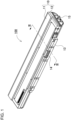
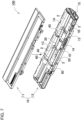
- FIG. 1 is a perspective view showing battery pack 100 according to the first exemplary embodiment
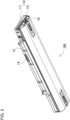
- FIG. 2 is a perspective view of battery pack 100 of FIG. 1 as obliquely viewed from below
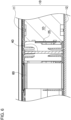
- FIG. 3 is a cross-sectional view of battery pack 100 of FIG. 1 taken along line III-III
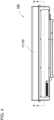
- FIG. 4 is a plan view of battery pack 100 of FIG. 1
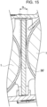
- FIG. 5 is a cross-sectional view taken along line V-V of FIG. 4
- FIG. 6 is an enlarged cross-sectional view of FIG. 5
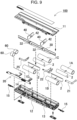
- FIG. 7 is an exploded perspective view showing a state of the battery pack of FIG.
- FIG. 8 is a plan view of the battery pack of FIG. 7
- FIG. 9 is an exploded perspective view of FIG. 4
- FIG. 10 is an exploded perspective view showing a state of the battery pack of FIG. 8 from which a longitudinal partition plate and lateral partition plates are removed
- FIG. 11 is an exploded perspective view showing a state of the battery pack of FIG. 10 from which insulating thermal resistant plates, secondary battery cells, and heat absorbers are disassembled.
- Battery pack 100 houses a plurality of secondary battery cells 1 inside, and connects secondary battery cells 100 in series or in parallel to achieve a capacity increase and allow charging and discharging. Power is supplied by connecting battery pack 100 to an external device corresponding to a driving target, and discharging secondary battery cells 1.
- battery pack 100 is connected to an external device constituted by a laptop computer.
- the external device to which the battery pack of the present invention is connected is not limited to the laptop computer, but may be other electronic devices and electric devices, such as a cellular phone, a portable digital versatile disc (DVD) player, a portable car navigation system, and a portable music player, or an electric tool or an assisted bicycle, for example.
- the battery pack may be directly and detachably attached to an external device for use, or may be housed or embedded inside an external device, or may be connected via a cable or the like.
- Battery pack 100 has a box-shaped external appearance extending in one direction as shown in FIGS. 1 , 2 , 4 , and 5 , and other figures.
- a box-shaped main body is constituted by housing case 10, and is divided into two parts, i.e., cover 11 and case body 12, as shown in FIGS. 3 , 5 , 7 , and 9 .
- Housing case 10 includes connector 14, and connection mechanism 13 for connecting to an electric device (a laptop computer herein) corresponding to a driving target to which power is supplied using battery pack 100.
- Lock mechanism 15 may be further provided to maintain an attached state of battery pack 100 to an electric device.
- Housing case 10 is made of a material having excellent electrical insulation and thermal insulation properties, such as polycarbonate and other resins.
- each of secondary battery cells 1 is constituted by a cylindrical secondary battery cell having a cylindrical exterior can.
- Secondary battery cells 1 herein are constituted by four secondary battery cells, i.e., first secondary battery cell 1A, second secondary battery cell 1B, third secondary battery cell 1C, and fourth secondary battery cell 1D. Two battery rows, each constituted by two of these cells connected in series, are connected in parallel. A number and a connection form of the secondary battery cells may be freely varied.
- Each of secondary battery cells 1 having a cylindrical shape is a lithium ion secondary battery.
- each of the secondary battery cells having a cylindrical shape may be constituted by a chargeable/dischargeable secondary battery such as a nickel metal hydride battery and a nickelcadmium battery, especially a battery that generates high-temperature heat in a use state.
- secondary battery cells 1A, 1B, 1C, 1D are electrically connected to each other in series or in parallel by lead plates 21, 22, 25.
- lead plates 21, 22, 25 is produced by bending a metal sheet having excellent conductivity.
- Lead plates 21, 22, 25 are welded to electrodes on end surfaces of secondary battery cells 1A, 1B, 1C, 1D.
- total + and total - of a battery assembly constituted by secondary battery cells 1A, 1B, 1C, 1D connected to each other are connected to circuit board 20.
- a charge/discharge circuit and a protection circuit are mounted on circuit board 20.
- an intermediate potential lead wire for measuring intermediate potential, or potential of a temperature detector for detecting each temperature of secondary battery cells 1 may be connected to circuit board 20 to recognize each voltage of secondary battery cells 1.
- a thermistor or the like is used as the temperature detector.
- connector 14 is directly connected to circuit board 20, and is disposed in a vertical posture on a side surface side of housing case 10.
- battery housing spaces 16 are partitioned inside housing case 10 to house secondary battery cells 1.
- Longitudinal partition plate 30 and lateral partition plates 40 are disposed in housing case 10 to partition battery housing spaces 16.
- Longitudinal partition plate 30 extends in a longitudinal direction of housing case 10. That is, longitudinal partition plate 30 is disposed substantially parallel to side walls 17 and substantially at a center between side walls 17 to divide an internal space of housing case 10 into two parts. Side walls 17 are located on both sides extending in the longitudinal direction of housing case 10.
- Longitudinal partition plate 30 is made of a material having excellent electrical insulation and thermal insulation properties, such as mica.
- lateral partition plates 40 extend in a lateral direction of housing case 10, that is, substantially parallel to end walls 18 located at both ends of housing case 10 in the longitudinal direction, and are disposed in such positions as to divide the internal space of housing case 10 into three parts in the longitudinal direction of housing case 10 between end walls 18.
- Each of lateral partition plates 40 is made of a material having excellent electrical insulation and thermal insulation properties.
- Each of lateral partition plates 40 is preferably made of mica. Mica is highly flame-retardant and non-flammable, has an excellent electrical insulation property, and is relatively inexpensive, and therefore is suitable for a part requiring thermal insulation and electrical insulation properties.
- Slits are formed in the respective partition plates to allow longitudinal partition plate 30 lateral partition plates 40 to cross each other in right-angled postures.
- Longitudinal partition plate 30 has longitudinal side slits 32, while each of lateral partition plates 40 has lateral side slit 42.
- Each width of the slits is made slightly larger than a thickness of the other partition plate crossing the corresponding slit.
- housing case 10 is divided into six parts as shown in FIGS. 10 and 11 by combining longitudinal partition plate 30 and lateral partition plates 40 to partition battery housing spaces 16 in some of which corresponding secondary battery cell 1 are housed. Secondary battery cells 1 housed in corresponding battery housing spaces 16 formed individually are physically separated from each other. As a result, electrical insulation and thermal insulation between secondary battery cells 1 are achieved.
- one longitudinal partition plate 30 disposed in parallel to the longitudinal direction is used to divide the internal space of housing case 10 into two parts in the lateral direction.
- Two or more longitudinal partition plates may be used to divide the internal space of the housing case into three or more parts.
- two lateral partition plates 40 disposed in parallel to the lateral direction is used to divide the internal space of the housing case into three parts.
- One lateral partition plate may be used to divide the internal space of the housing case into two parts, or three or more lateral partition plates may be used to divide the internal space of the housing case into four or more parts.
- the number of the secondary battery cells is made smaller than the number of battery housing spaces.
- the number of secondary battery cells 1 is four even in a state where six battery housing spaces 16 are formed.
- first secondary battery cell 1A, second secondary battery cell 1B, third secondary battery cell 1C, and fourth secondary battery cells 1D are used as the four secondary battery cells.
- battery rows each constituted by two of these cells connected in series are connected to each other in parallel.
- two secondary battery cells, i.e., first secondary battery cell 1A and third secondary battery cell 1C are disposed such that end surfaces of these battery cells face each other to constitute a first battery row
- two secondary battery cells i.e., second secondary battery cell 1B and fourth secondary battery cell 1D are disposed such that end surfaces of these battery cells face each other to constitute a second battery row.
- a number of series connections need not necessarily be two or more.
- Each of the battery rows may be constituted by one secondary battery cell and connected to each other in parallel.
- longitudinal side slits 32 are formed at an upper end side of longitudinal partition plate 30, while lateral side slit 42 is formed at a lower end side of each of lateral partition plates 40.
- lead slits 31 through which lead plates 22, 25 are inserted are formed in longitudinal partition plate 30 separately from longitudinal side slits 32. Lead slits 31 thus formed are provided on the lower end side of longitudinal partition plate 30. Lead slits 31 and longitudinal side slits 32 are formed at the opposite edges as described above. This configuration eliminates the necessity of work for setting longitudinal partition plate 30 in a state where lead plates 22, 25 and lateral partition plates 40 have been set in housing case 10 in advance.
- this configuration eliminates the necessity for positional alignment to allow simultaneous insertion of lead plates 22, 25 and lateral partition plates 40 into the lead slits and the longitudinal side slits at the time of setting of longitudinal partition plate 30 in housing case 10.
- lead plates 22, 25 or lateral partition plates 40 may be initially guided to lead slit 31 to set longitudinal partition plate 30, and then lateral partition plates 40 may be set to position only lateral side slits 42. Workability improves by dividing the positioning work for the slits in this manner.
- longitudinal side slits 32 and lateral side slits 42 of longitudinal partition plate 30 and lateral partition plates 40 may be formed in opposite directions. That is, the lead plates may be inserted into longitudinal side slits 32.
- the longitudinal side slits are common slits into which the lead plates and the lateral partition plates are both inserted. This configuration prevents formation of an additional gap, thereby improving safety.
- a number of lateral partition plates 40 for defining battery housing spaces 16 is adjustable according to required thermal insulation performance. While the number of the plates is one in the example of FIG. 11 , the number may be two or more.
- a pair of ribs for holding longitudinal partition plate 30 are further formed on the inner surface of housing case 10. Specifically, as shown in a cross-sectional view of FIG. 3 , a pair of ribs 34 extending in the longitudinal direction are provided upright on the inner surface of case body 12 of housing case 10 at a substantially central position. Each of ribs 34 is formed integrally with case body 12 and cover 11. A lower end of longitudinal partition plate 30 is inserted between the pair of ribs 34 to hold longitudinal partition plate 30 inside housing case 10.
- an interface between the respective ribs and longitudinal partition plate 30 is filled with flame-retardant adhesive material 36.
- a gap between the ribs and longitudinal partition plate 30 is filled in this manner to avoid such a situation where flame exhaust possibly produced during thermal runaway of the secondary battery cell reaches the adjacent secondary battery cell.
- longitudinal partition plate 30 is disposed between the side surfaces of the secondary battery cells to prevent damage to the adjacent different secondary battery cell by using longitudinal partition plate 30 even when one of the secondary battery cells causes thermal runaway and blows out flame or high-pressure gas toward the side surface.
- flame is considered to leak toward an adjacent secondary battery cell through gap 35Y when gap 35Y is present at a connecting portion between ribs 34Y and longitudinal partition plate 30Y.
- a gap between ribs 34 and the lower end of longitudinal partition plate 30, and an upper end of longitudinal partition plate 30 are filled with flame-retardant adhesive material 36 to fill the gap.
- Flame-retardant adhesive material 36 may be made of silicone resin or the like.
- a temporary sealing effect is produced by filling the gap with adhesive material 36 thus provided.
- blowout of flame and high-pressure gas generally continues for a short period of approximately a few seconds. In this case, direct exposure of the adjacent secondary battery cell to flame or high-pressure gas is avoidable if strength of the flame or the high-pressure gas is reduced. Accordingly, sufficient fire spread preventing effect is expected to be achieved.
- each of the secondary battery cells is covered with insulating thermal resistant plate 2.
- Insulating thermal resistant plates 2 are provided so as to cover at least opposing regions of respective side faces of secondary battery cells 1 disposed adjacent to each other such that these side faces face each other.
- Each of insulating thermal resistant plates 2 is curved along the side surface of corresponding secondary battery cell 1. According to this configuration, each of insulating thermal resistant plates 2 is capable of covering corresponding secondary battery cell 2 along the side surface in a posture easily coming into close contact with the side surface, thereby efficiently improving a thermal insulation property in a limited space.
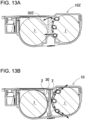
- Each of insulating thermal resistant plates 2 shown in FIG. 3 and other figures is curved in a U shape around a position where a pair of secondary battery cells 1 come closest to each other in a cross-sectional view.
- a flame exhaust direction can be regulated such that flame exhaust caused by secondary battery cell 1 flows not toward the side surface but toward a rear side in an up-down direction. Accordingly, safety improves.
- each of insulating thermal resistant plates 2 may contain a fibrous material.
- each of insulating thermal resistant plates 2 is constituted by a plate member made of an inorganic material. It is preferable that each of insulating thermal resistant plates 2 is made of mica. This configuration achieves high thermal resistance at low cost.
- longitudinal partition plate 30 constitutes thermal insulator 50.
- first thermal insulator 51 is provided on a side facing a side surface of the cylindrical shape of first secondary battery cell 1A on the right side, and projects to come into contact with this side surface of the cylindrical shape.
- second thermal insulator 52 is provided on a side facing a side surface of a cylindrical shape of second secondary battery cell 1B on the left side, and projects to come into contact with this side surface of the cylindrical shape. This configuration brings a partially projected portion of longitudinal partition plate 30 into contact with the side surface of the cylindrical shape of the secondary battery cell, thereby separating longitudinal partition plate 30 from the secondary battery cell to form an air layer which improves a thermal insulation property.
- battery pack 100 includes thermal insulator 50 partially projected from both surfaces of longitudinal partition plate 30.
- This thermal insulator is disposed at a position in contact with a vicinity of a top of the side surface of the cylindrical shape of secondary battery cell 1 to make distance D12 between the secondary battery cells longer than distance D11 the secondary battery cells of a configuration including no thermal insulator as shown in FIG. 15 .
- the air layer between the secondary battery cells enlarges by separation between the secondary battery cells. Accordingly, the enlarged air layer functions as a thermal insulating layer, thereby improving the thermal insulating effect between the secondary battery cells.
- this configuration allows reduction of the thickness of the longitudinal partition plate itself, thereby contributing to weight reduction of the entire battery pack.
- Thermal insulator 50 may be formed integrally with longitudinal partition plate 30, but is preferably a member separated from longitudinal partition plate 30.
- a material different from the material of the longitudinal partition plate is available to constitute the thermal insulator.
- Thermal insulator 50 is therefore allowed to be made of a material having a higher thermal insulation property than the material of longitudinal partition plate 30. Accordingly, reduction of cost and weight is achievable by providing a member exhibiting higher heat insulation not on the entire surface of longitudinal partition plate 30 but on a part of the surface.
- mica is preferably used as the material of thermal insulator 50 having an excellent thermal insulation property.
- thermal insulator 50 is a member separated from longitudinal partition plate 30, the thermal insulator is bonded to the surface of longitudinal partition plate 30. A double-sided tape or an adhesive is used for this bonding.
- thermal insulator 50 may be extended in the longitudinal direction of longitudinal partition plate 30, or may be partially cut off in the longitudinal direction. In the example of FIG. 10 and other figures, thermal insulator 50 is cut off at the portions where the longitudinal side slits 32 are formed. In addition, the thermal insulator may be extended in a slit shape as described above, or may be parts having rectangular shapes and provided separately from each other. Even when the thermal insulator is partially provided in the longitudinal direction, the thermal insulator is capable of forming a thermal insulating layer by coming into contact with the side surface of the cylindrical secondary battery cell in contact with the thermal insulator. Moreover, the volume of the thermal insulator to be used decreases, wherefore reduction of cost and weight is achievable.
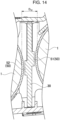
- first thermal insulator 51 and second thermal insulator 52 may be disposed such that centers of respective insulators 51 and 52 are shifted from each other in a left-right direction of longitudinal partition plate 30 in the cross-sectional view as shown in FIG. 14 .
- centers of the cross sections of left and right secondary battery cells 1 are shifted from each other in the left-right direction of longitudinal partition plate 30. Accordingly, concentration of the stresses is reduced.
- first thermal insulator 51 and second thermal insulator 52 are preferably arranged so as to partially overlap with each other in the left-right direction of longitudinal partition plate 30. In this manner, mechanical rigidity increases.
- Thermal runaway is reduced by disposing heat absorbers 60 inside the housing case.
- each of heat absorbers 60 absorbs heat generated by the secondary battery cell causing thermal runaway in a case of thermal runaway caused by any one of the secondary battery cells inside the housing case, thereby reducing a chain of thermal runaway to the adjacent secondary battery cell.
- the number of battery housing spaces 16 is larger than the number of the secondary battery cells.
- heat absorbers 60 are allowed to be disposed in the battery housing spaces where the secondary battery cells are not housed. Accordingly, efficient disposition of heat absorbers 60 is achievable inside the housing case having a limited volume without the necessity of preparing a space dedicated for heat absorbers 60.
- Each of heat absorbers 60 is a metal part having a cylindrical shape which is hollow inside. This shape increases a surface area and enhances a heat absorption effect while reducing a weight of heat absorber 60.
- An aluminum pipe can be preferably used as heat absorber 60 made of metal. Aluminum has stable characteristics such as lightweight, high heat transfer property, low-cost, and no corrosion.
- heat absorber 60 is not necessarily required to have the same length as the length of the secondary battery cell, and may be shorter than the length of the secondary battery cell. This reduction of the length can reduce material cost and weight.
- the length of heat absorber 60 is appropriately set according to a required amount of heat absorption such as the capacity of the secondary battery cell to be used and the temperature at the time of heat generation.
- heat absorber 60 When heat absorbing body 60 is shortened, heat absorber 60 is fixed without movement in corresponding battery housing space 16. For example, double-sided tape or adhesive is used. When heat absorber 60 is made shorter than the secondary battery cell, heat absorber 60 is eccentrically fixed in battery housing space 16 in such a manner as to come close to different battery housing space 16 which is located adjacent to corresponding battery housing space 16 in the longitudinal direction, and houses the different secondary battery cell. By disposing heat absorber 60 close to the end surface of the secondary battery cell corresponding to a heat absorbing target, the heat absorbing effect can be effectively exerted during heat generation from the corresponding secondary battery cell.
- the battery pack according to the present invention is suitably applicable to a chargeable/dischargeable battery pack for a battery-driven device such as a laptop computer, a cellular phone, a portable digital versatile disc (DVD) player, a portable car navigation system, a portable music player, a power tool, and an assisted bicycle.
- a battery-driven device such as a laptop computer, a cellular phone, a portable digital versatile disc (DVD) player, a portable car navigation system, a portable music player, a power tool, and an assisted bicycle.
Landscapes
- Chemical & Material Sciences (AREA)
- Chemical Kinetics & Catalysis (AREA)
- Electrochemistry (AREA)
- General Chemical & Material Sciences (AREA)
- Engineering & Computer Science (AREA)
- Manufacturing & Machinery (AREA)
- Life Sciences & Earth Sciences (AREA)
- Biophysics (AREA)
- Battery Mounting, Suspending (AREA)
- Secondary Cells (AREA)
Claims (9)
- Batteriepack, umfassend:eine Vielzahl von Sekundärbatteriezellen (1), die miteinander in Reihe und/oder parallel geschaltet sind; undeinen Gehäusekasten (10), der eine Vielzahl von Batteriegehäuseräumen (16) für jedes Gehäuse umfasst, die einer der Vielzahl von Sekundärbatteriezellen (1) entsprechen, wobeieine Anzahl der Vielzahl von Batteriegehäuseräumen (16) größer als eine Anzahl der Vielzahl von Sekundärbatteriezellen (1) ist, undeinen Wärmeabsorber (60), der in einem der Vielzahl von Batteriegehäuseräumen (16) angeordnet ist, wobei der eine von der Vielzahl von Batteriegehäuseräumen (16) keine der Vielzahl von Sekundärbatteriezellen (1) unterbringt,dadurch gekennzeichnet, dass der Wärmeabsorber (60) ein Metallteil ist, das innen einen säulenförmigen Hohlraum aufweist.
- Batteriepack nach Anspruch 1, wobei jede der Vielzahl von Sekundärbatteriezellen (1) ein zylindrisches Außenrohr aufweist.
- Batteriepack nach einem der Ansprüche 1 bis 2, wobei der Wärmeabsorber (60) eine Länge aufweist, die kleiner als eine Länge von jeder der Vielzahl von Sekundärbatteriezellen (1) ist.
- Batteriepack nach Anspruch 3, wobei der Wärmeabsorber (60) exzentrisch in dem einen der Vielzahl von Batteriegehäuseräumen auf einer Seite angeordnet ist, die nahe an einem unterschiedlichen der Vielzahl von Batteriegehäuseräumen (16) liegt, wo eine der Vielzahl von Sekundärbatteriezellen (1) untergebracht ist, wobei der eine unterschiedliche der Vielzahl von Batteriegehäuseräumen (16) benachbart zu dem einen der Vielzahl von Batteriegehäuseräumen (16) in einer Längsrichtung des einen der Vielzahl von Batteriegehäuseräumen (16) liegt.
- Batteriepack nach einem der Ansprüche 1 bis 4, wobei der Wärmeabsorber (60) aus Aluminium besteht.
- Batteriepack nach einem der Ansprüche 1 bis 5, ferner umfassend eine Längstrennplatte (30), die sich in einer Längsrichtung des Gehäusekastens (10) erstreckt und ein Inneres des Gehäusekastens (10) in einer seitlichen Richtung orthogonal zur Längsrichtung teilt, um die Vielzahl von Batteriegehäuseräumen (16) abzuteilen.
- Batteriepack nach Anspruch 6, ferner umfassend eine seitliche Trennplatte (40), welche die Längstrennplatte (30) durchquert und die Vielzahl von Batteriegehäuseräumen (16) bildet.
- Batteriepack nach einem der Ansprüche 1 bis 7, wobeiSeitenoberflächen der Vielzahl von Sekundärbatteriezellen (1) durch isolierende thermisch beständige Platten (2) bedeckt sind, undjede der isolierenden thermisch beständigen Platten (2) um eine Position gekrümmt ist, wo benachbarte der Vielzahl von Sekundärbatteriezellen (1) einander in einer Querschnittsansicht am nächsten kommen.
- Batteriepack nach Anspruch 8, wobei jede der isolierenden thermisch beständigen Platten (2) aus Glimmer besteht.
Applications Claiming Priority (2)
| Application Number | Priority Date | Filing Date | Title |
|---|---|---|---|
| JP2018015673 | 2018-01-31 | ||
| PCT/JP2018/045411 WO2019150773A1 (ja) | 2018-01-31 | 2018-12-11 | 電池パック |
Publications (3)
| Publication Number | Publication Date |
|---|---|
| EP3748717A1 EP3748717A1 (de) | 2020-12-09 |
| EP3748717A4 EP3748717A4 (de) | 2021-04-07 |
| EP3748717B1 true EP3748717B1 (de) | 2025-02-05 |
Family
ID=67479210
Family Applications (1)
| Application Number | Title | Priority Date | Filing Date |
|---|---|---|---|
| EP18903941.5A Active EP3748717B1 (de) | 2018-01-31 | 2018-12-11 | Batteriepack |
Country Status (5)
| Country | Link |
|---|---|
| US (1) | US11495843B2 (de) |
| EP (1) | EP3748717B1 (de) |
| JP (1) | JP7212636B2 (de) |
| CN (1) | CN111512466A (de) |
| WO (1) | WO2019150773A1 (de) |
Families Citing this family (3)
| Publication number | Priority date | Publication date | Assignee | Title |
|---|---|---|---|---|
| WO2023176227A1 (ja) * | 2022-03-18 | 2023-09-21 | パナソニックエナジー株式会社 | 電池パック及びその製造方法 |
| CN119174041A (zh) * | 2022-06-15 | 2024-12-20 | 株式会社 Lg新能源 | 二次电池组 |
| KR20250035236A (ko) * | 2023-09-05 | 2025-03-12 | 삼성에스디아이 주식회사 | 배터리 셀 홀더 및 이를 포함하는 배터리 모듈 |
Family Cites Families (20)
| Publication number | Priority date | Publication date | Assignee | Title |
|---|---|---|---|---|
| JPH0680260A (ja) | 1992-05-29 | 1994-03-22 | Nec Corp | 紙葉類の供給装置 |
| JPH0680260U (ja) | 1993-04-22 | 1994-11-08 | 富士電気化学株式会社 | 集合電池 |
| JPH1029172A (ja) * | 1996-07-12 | 1998-02-03 | Nippon Electric Ind Co Ltd | 充電式電動工具の電池パック及びこの電池パック用ダミー電池 |
| US6187470B1 (en) * | 1997-06-10 | 2001-02-13 | Roland K. Peterson | Solderless battery cell holder |
| US6705418B2 (en) * | 2000-10-31 | 2004-03-16 | Volvo Car Corporation | Arrangement for providing a compact battery with autonomous cooling |
| JP4485187B2 (ja) * | 2003-12-24 | 2010-06-16 | 本田技研工業株式会社 | バッテリケース |
| US7989104B2 (en) * | 2004-10-28 | 2011-08-02 | Samsung Sdi Co., Ltd. | Battery module |
| JP2008140629A (ja) * | 2006-11-30 | 2008-06-19 | Sanyo Electric Co Ltd | パック電池 |
| EP2398108A4 (de) * | 2009-11-25 | 2012-08-22 | Panasonic Corp | Batteriemodul |
| JPWO2011114625A1 (ja) * | 2010-03-15 | 2013-06-27 | パナソニック株式会社 | 電池パック |
| JP2012033464A (ja) * | 2010-07-02 | 2012-02-16 | Sanyo Electric Co Ltd | パック電池 |
| JP2012146403A (ja) | 2011-01-07 | 2012-08-02 | Panasonic Corp | 電池パック |
| JP2012144360A (ja) * | 2011-01-14 | 2012-08-02 | Mitsubishi Electric Corp | エレベータのバッテリモジュール |
| US8609266B2 (en) * | 2011-02-18 | 2013-12-17 | Samsung Sdi Co., Ltd. | Battery pack |
| JP5726605B2 (ja) | 2011-04-12 | 2015-06-03 | 日立オートモティブシステムズ株式会社 | 組電池を内蔵した電池ブロックおよび蓄電装置 |
| CN106058100B (zh) * | 2012-09-06 | 2018-11-13 | 阿提瓦公司 | 框架具有点胶挡止的电池组件 |
| JP2014086342A (ja) | 2012-10-25 | 2014-05-12 | Sanyo Electric Co Ltd | 電池パックとその製造方法 |
| US8920955B1 (en) * | 2012-12-13 | 2014-12-30 | Atieva, Inc. | Battery module with high thermal conductivity and assembling method thereof |
| JP6127524B2 (ja) * | 2013-01-11 | 2017-05-17 | 株式会社豊田自動織機 | 電池パック |
| KR101620263B1 (ko) * | 2015-02-13 | 2016-05-12 | 엘지전자 주식회사 | 진공 청소, 배터리 어셈블리 및 충전대 |
-
2018
- 2018-12-11 US US16/965,671 patent/US11495843B2/en active Active
- 2018-12-11 WO PCT/JP2018/045411 patent/WO2019150773A1/ja not_active Ceased
- 2018-12-11 EP EP18903941.5A patent/EP3748717B1/de active Active
- 2018-12-11 JP JP2019568908A patent/JP7212636B2/ja active Active
- 2018-12-11 CN CN201880083376.XA patent/CN111512466A/zh active Pending
Also Published As
| Publication number | Publication date |
|---|---|
| CN111512466A (zh) | 2020-08-07 |
| JPWO2019150773A1 (ja) | 2021-01-28 |
| US11495843B2 (en) | 2022-11-08 |
| US20210043988A1 (en) | 2021-02-11 |
| EP3748717A1 (de) | 2020-12-09 |
| WO2019150773A1 (ja) | 2019-08-08 |
| EP3748717A4 (de) | 2021-04-07 |
| JP7212636B2 (ja) | 2023-01-25 |
Similar Documents
| Publication | Publication Date | Title |
|---|---|---|
| US11502347B2 (en) | Battery pack | |
| EP3748713B1 (de) | Batteriepack | |
| KR20220142853A (ko) | 배터리 팩 및 그 제조방법 | |
| CN101395740B (zh) | 中型或大型电池模块 | |
| KR20220120916A (ko) | 전지 모듈 및 이를 포함하는 전지팩 | |
| JP2020502736A (ja) | バッテリーモジュール | |
| CN104584264B (zh) | 电池组 | |
| JP2021504888A (ja) | 改善された冷却構造を有するバッテリーモジュール | |
| US11489218B2 (en) | Battery pack | |
| CN111937180B (zh) | 包括内部板的电池模块、包括该电池模块的电池组及车辆 | |
| EP3748717B1 (de) | Batteriepack | |
| JP2009277433A (ja) | バッテリパック | |
| CN107887540B (zh) | 电池组 | |
| CN112005401B (zh) | 电源装置 | |
| CN104037366A (zh) | 可再充电电池组 | |
| KR20250178559A (ko) | 배터리 모듈, 이를 포함하는 배터리 팩 및 자동차 | |
| CN121195402A (zh) | 电池模块及包括该电池模块的电池组和车辆 | |
| KR20140109693A (ko) | 이차 전지 팩 |
Legal Events
| Date | Code | Title | Description |
|---|---|---|---|
| STAA | Information on the status of an ep patent application or granted ep patent |
Free format text: STATUS: THE INTERNATIONAL PUBLICATION HAS BEEN MADE |
|
| PUAI | Public reference made under article 153(3) epc to a published international application that has entered the european phase |
Free format text: ORIGINAL CODE: 0009012 |
|
| STAA | Information on the status of an ep patent application or granted ep patent |
Free format text: STATUS: REQUEST FOR EXAMINATION WAS MADE |
|
| 17P | Request for examination filed |
Effective date: 20200828 |
|
| AK | Designated contracting states |
Kind code of ref document: A1 Designated state(s): AL AT BE BG CH CY CZ DE DK EE ES FI FR GB GR HR HU IE IS IT LI LT LU LV MC MK MT NL NO PL PT RO RS SE SI SK SM TR |
|
| AX | Request for extension of the european patent |
Extension state: BA ME |
|
| REG | Reference to a national code |
Ref country code: DE Ref legal event code: R079 Free format text: PREVIOUS MAIN CLASS: H01M0002100000 Ref country code: DE Ref legal event code: R079 Ref document number: 602018079001 Country of ref document: DE Free format text: PREVIOUS MAIN CLASS: H01M0002100000 Ipc: H01M0050213000 |
|
| A4 | Supplementary search report drawn up and despatched |
Effective date: 20210309 |
|
| RIC1 | Information provided on ipc code assigned before grant |
Ipc: H01M 10/613 20140101ALI20210302BHEP Ipc: H01M 10/653 20140101ALI20210302BHEP Ipc: H01M 50/213 20210101AFI20210302BHEP Ipc: H01M 10/643 20140101ALI20210302BHEP Ipc: H01M 50/20 20210101ALI20210302BHEP Ipc: H01M 10/6555 20140101ALI20210302BHEP |
|
| DAV | Request for validation of the european patent (deleted) | ||
| DAX | Request for extension of the european patent (deleted) | ||
| GRAP | Despatch of communication of intention to grant a patent |
Free format text: ORIGINAL CODE: EPIDOSNIGR1 |
|
| STAA | Information on the status of an ep patent application or granted ep patent |
Free format text: STATUS: GRANT OF PATENT IS INTENDED |
|
| INTG | Intention to grant announced |
Effective date: 20240829 |
|
| RAP3 | Party data changed (applicant data changed or rights of an application transferred) |
Owner name: SANYO ELECTRIC CO., LTD. |
|
| GRAS | Grant fee paid |
Free format text: ORIGINAL CODE: EPIDOSNIGR3 |
|
| GRAA | (expected) grant |
Free format text: ORIGINAL CODE: 0009210 |
|
| STAA | Information on the status of an ep patent application or granted ep patent |
Free format text: STATUS: THE PATENT HAS BEEN GRANTED |
|
| RAP1 | Party data changed (applicant data changed or rights of an application transferred) |
Owner name: PANASONIC ENERGY CO., LTD. |
|
| AK | Designated contracting states |
Kind code of ref document: B1 Designated state(s): AL AT BE BG CH CY CZ DE DK EE ES FI FR GB GR HR HU IE IS IT LI LT LU LV MC MK MT NL NO PL PT RO RS SE SI SK SM TR |
|
| REG | Reference to a national code |
Ref country code: GB Ref legal event code: FG4D |
|
| REG | Reference to a national code |
Ref country code: CH Ref legal event code: EP |
|
| REG | Reference to a national code |
Ref country code: DE Ref legal event code: R096 Ref document number: 602018079001 Country of ref document: DE |
|
| REG | Reference to a national code |
Ref country code: IE Ref legal event code: FG4D |
|
| REG | Reference to a national code |
Ref country code: NL Ref legal event code: MP Effective date: 20250205 |
|
| PG25 | Lapsed in a contracting state [announced via postgrant information from national office to epo] |
Ref country code: RS Free format text: LAPSE BECAUSE OF FAILURE TO SUBMIT A TRANSLATION OF THE DESCRIPTION OR TO PAY THE FEE WITHIN THE PRESCRIBED TIME-LIMIT Effective date: 20250505 |
|
| PG25 | Lapsed in a contracting state [announced via postgrant information from national office to epo] |
Ref country code: FI Free format text: LAPSE BECAUSE OF FAILURE TO SUBMIT A TRANSLATION OF THE DESCRIPTION OR TO PAY THE FEE WITHIN THE PRESCRIBED TIME-LIMIT Effective date: 20250205 |
|
| PG25 | Lapsed in a contracting state [announced via postgrant information from national office to epo] |
Ref country code: PL Free format text: LAPSE BECAUSE OF FAILURE TO SUBMIT A TRANSLATION OF THE DESCRIPTION OR TO PAY THE FEE WITHIN THE PRESCRIBED TIME-LIMIT Effective date: 20250205 |
|
| PG25 | Lapsed in a contracting state [announced via postgrant information from national office to epo] |
Ref country code: ES Free format text: LAPSE BECAUSE OF FAILURE TO SUBMIT A TRANSLATION OF THE DESCRIPTION OR TO PAY THE FEE WITHIN THE PRESCRIBED TIME-LIMIT Effective date: 20250205 |
|
| REG | Reference to a national code |
Ref country code: LT Ref legal event code: MG9D |
|
| PG25 | Lapsed in a contracting state [announced via postgrant information from national office to epo] |
Ref country code: NO Free format text: LAPSE BECAUSE OF FAILURE TO SUBMIT A TRANSLATION OF THE DESCRIPTION OR TO PAY THE FEE WITHIN THE PRESCRIBED TIME-LIMIT Effective date: 20250505 Ref country code: IS Free format text: LAPSE BECAUSE OF FAILURE TO SUBMIT A TRANSLATION OF THE DESCRIPTION OR TO PAY THE FEE WITHIN THE PRESCRIBED TIME-LIMIT Effective date: 20250605 |
|
| PG25 | Lapsed in a contracting state [announced via postgrant information from national office to epo] |
Ref country code: NL Free format text: LAPSE BECAUSE OF FAILURE TO SUBMIT A TRANSLATION OF THE DESCRIPTION OR TO PAY THE FEE WITHIN THE PRESCRIBED TIME-LIMIT Effective date: 20250205 |
|
| PG25 | Lapsed in a contracting state [announced via postgrant information from national office to epo] |
Ref country code: HR Free format text: LAPSE BECAUSE OF FAILURE TO SUBMIT A TRANSLATION OF THE DESCRIPTION OR TO PAY THE FEE WITHIN THE PRESCRIBED TIME-LIMIT Effective date: 20250205 |
|
| PG25 | Lapsed in a contracting state [announced via postgrant information from national office to epo] |
Ref country code: LV Free format text: LAPSE BECAUSE OF FAILURE TO SUBMIT A TRANSLATION OF THE DESCRIPTION OR TO PAY THE FEE WITHIN THE PRESCRIBED TIME-LIMIT Effective date: 20250205 Ref country code: PT Free format text: LAPSE BECAUSE OF FAILURE TO SUBMIT A TRANSLATION OF THE DESCRIPTION OR TO PAY THE FEE WITHIN THE PRESCRIBED TIME-LIMIT Effective date: 20250605 |
|
| PG25 | Lapsed in a contracting state [announced via postgrant information from national office to epo] |
Ref country code: BG Free format text: LAPSE BECAUSE OF FAILURE TO SUBMIT A TRANSLATION OF THE DESCRIPTION OR TO PAY THE FEE WITHIN THE PRESCRIBED TIME-LIMIT Effective date: 20250205 Ref country code: GR Free format text: LAPSE BECAUSE OF FAILURE TO SUBMIT A TRANSLATION OF THE DESCRIPTION OR TO PAY THE FEE WITHIN THE PRESCRIBED TIME-LIMIT Effective date: 20250506 |
|
| REG | Reference to a national code |
Ref country code: AT Ref legal event code: MK05 Ref document number: 1765057 Country of ref document: AT Kind code of ref document: T Effective date: 20250205 |
|
| PG25 | Lapsed in a contracting state [announced via postgrant information from national office to epo] |
Ref country code: SE Free format text: LAPSE BECAUSE OF FAILURE TO SUBMIT A TRANSLATION OF THE DESCRIPTION OR TO PAY THE FEE WITHIN THE PRESCRIBED TIME-LIMIT Effective date: 20250205 |
|
| PG25 | Lapsed in a contracting state [announced via postgrant information from national office to epo] |
Ref country code: SM Free format text: LAPSE BECAUSE OF FAILURE TO SUBMIT A TRANSLATION OF THE DESCRIPTION OR TO PAY THE FEE WITHIN THE PRESCRIBED TIME-LIMIT Effective date: 20250205 |
|
| PG25 | Lapsed in a contracting state [announced via postgrant information from national office to epo] |
Ref country code: DK Free format text: LAPSE BECAUSE OF FAILURE TO SUBMIT A TRANSLATION OF THE DESCRIPTION OR TO PAY THE FEE WITHIN THE PRESCRIBED TIME-LIMIT Effective date: 20250205 |
|
| PG25 | Lapsed in a contracting state [announced via postgrant information from national office to epo] |
Ref country code: IT Free format text: LAPSE BECAUSE OF FAILURE TO SUBMIT A TRANSLATION OF THE DESCRIPTION OR TO PAY THE FEE WITHIN THE PRESCRIBED TIME-LIMIT Effective date: 20250205 |
|
| PG25 | Lapsed in a contracting state [announced via postgrant information from national office to epo] |
Ref country code: AT Free format text: LAPSE BECAUSE OF FAILURE TO SUBMIT A TRANSLATION OF THE DESCRIPTION OR TO PAY THE FEE WITHIN THE PRESCRIBED TIME-LIMIT Effective date: 20250205 |
|
| PG25 | Lapsed in a contracting state [announced via postgrant information from national office to epo] |
Ref country code: CZ Free format text: LAPSE BECAUSE OF FAILURE TO SUBMIT A TRANSLATION OF THE DESCRIPTION OR TO PAY THE FEE WITHIN THE PRESCRIBED TIME-LIMIT Effective date: 20250205 Ref country code: EE Free format text: LAPSE BECAUSE OF FAILURE TO SUBMIT A TRANSLATION OF THE DESCRIPTION OR TO PAY THE FEE WITHIN THE PRESCRIBED TIME-LIMIT Effective date: 20250205 |
|
| PG25 | Lapsed in a contracting state [announced via postgrant information from national office to epo] |
Ref country code: RO Free format text: LAPSE BECAUSE OF FAILURE TO SUBMIT A TRANSLATION OF THE DESCRIPTION OR TO PAY THE FEE WITHIN THE PRESCRIBED TIME-LIMIT Effective date: 20250205 |
|
| PG25 | Lapsed in a contracting state [announced via postgrant information from national office to epo] |
Ref country code: SK Free format text: LAPSE BECAUSE OF FAILURE TO SUBMIT A TRANSLATION OF THE DESCRIPTION OR TO PAY THE FEE WITHIN THE PRESCRIBED TIME-LIMIT Effective date: 20250205 |
|
| REG | Reference to a national code |
Ref country code: DE Ref legal event code: R097 Ref document number: 602018079001 Country of ref document: DE |
|
| PLBE | No opposition filed within time limit |
Free format text: ORIGINAL CODE: 0009261 |
|
| STAA | Information on the status of an ep patent application or granted ep patent |
Free format text: STATUS: NO OPPOSITION FILED WITHIN TIME LIMIT |
|
| PGFP | Annual fee paid to national office [announced via postgrant information from national office to epo] |
Ref country code: DE Payment date: 20251211 Year of fee payment: 8 |
|
| PGFP | Annual fee paid to national office [announced via postgrant information from national office to epo] |
Ref country code: GB Payment date: 20251219 Year of fee payment: 8 |
|
| 26N | No opposition filed |
Effective date: 20251106 |
|
| PGFP | Annual fee paid to national office [announced via postgrant information from national office to epo] |
Ref country code: FR Payment date: 20251229 Year of fee payment: 8 |