EP3748714B1 - Bloc-piles - Google Patents
Bloc-piles Download PDFInfo
- Publication number
- EP3748714B1 EP3748714B1 EP18903451.5A EP18903451A EP3748714B1 EP 3748714 B1 EP3748714 B1 EP 3748714B1 EP 18903451 A EP18903451 A EP 18903451A EP 3748714 B1 EP3748714 B1 EP 3748714B1
- Authority
- EP
- European Patent Office
- Prior art keywords
- secondary battery
- battery cells
- partition plate
- battery pack
- flame
- Prior art date
- Legal status (The legal status is an assumption and is not a legal conclusion. Google has not performed a legal analysis and makes no representation as to the accuracy of the status listed.)
- Active
Links
- 238000005192 partition Methods 0.000 claims description 131
- 239000000463 material Substances 0.000 claims description 23
- 239000000853 adhesive Substances 0.000 claims description 12
- 230000001070 adhesive effect Effects 0.000 claims description 12
- 239000010445 mica Substances 0.000 claims description 10
- 229910052618 mica group Inorganic materials 0.000 claims description 10
- 238000010292 electrical insulation Methods 0.000 claims description 9
- RNFJDJUURJAICM-UHFFFAOYSA-N 2,2,4,4,6,6-hexaphenoxy-1,3,5-triaza-2$l^{5},4$l^{5},6$l^{5}-triphosphacyclohexa-1,3,5-triene Chemical compound N=1P(OC=2C=CC=CC=2)(OC=2C=CC=CC=2)=NP(OC=2C=CC=CC=2)(OC=2C=CC=CC=2)=NP=1(OC=1C=CC=CC=1)OC1=CC=CC=C1 RNFJDJUURJAICM-UHFFFAOYSA-N 0.000 claims description 8
- 239000003063 flame retardant Substances 0.000 claims description 8
- 230000036544 posture Effects 0.000 claims description 6
- 229910010272 inorganic material Inorganic materials 0.000 claims description 3
- 239000011147 inorganic material Substances 0.000 claims description 3
- 239000000835 fiber Substances 0.000 claims description 2
- 239000012212 insulator Substances 0.000 description 28
- 239000006096 absorbing agent Substances 0.000 description 20
- 238000009413 insulation Methods 0.000 description 16
- 230000000052 comparative effect Effects 0.000 description 9
- 230000000694 effects Effects 0.000 description 7
- 230000001105 regulatory effect Effects 0.000 description 7
- 230000009467 reduction Effects 0.000 description 6
- 238000010586 diagram Methods 0.000 description 5
- 229910052751 metal Inorganic materials 0.000 description 5
- 239000002184 metal Substances 0.000 description 5
- 230000007246 mechanism Effects 0.000 description 4
- 230000003405 preventing effect Effects 0.000 description 4
- PXHVJJICTQNCMI-UHFFFAOYSA-N nickel Substances [Ni] PXHVJJICTQNCMI-UHFFFAOYSA-N 0.000 description 3
- 238000010521 absorption reaction Methods 0.000 description 2
- 229910052782 aluminium Inorganic materials 0.000 description 2
- XAGFODPZIPBFFR-UHFFFAOYSA-N aluminium Chemical compound [Al] XAGFODPZIPBFFR-UHFFFAOYSA-N 0.000 description 2
- 230000015572 biosynthetic process Effects 0.000 description 2
- 230000001413 cellular effect Effects 0.000 description 2
- 230000008859 change Effects 0.000 description 2
- 238000007599 discharging Methods 0.000 description 2
- 230000020169 heat generation Effects 0.000 description 2
- 229910052759 nickel Inorganic materials 0.000 description 2
- 239000013585 weight reducing agent Substances 0.000 description 2
- HBBGRARXTFLTSG-UHFFFAOYSA-N Lithium ion Chemical compound [Li+] HBBGRARXTFLTSG-UHFFFAOYSA-N 0.000 description 1
- 238000005452 bending Methods 0.000 description 1
- 230000008901 benefit Effects 0.000 description 1
- 239000000470 constituent Substances 0.000 description 1
- 230000007797 corrosion Effects 0.000 description 1
- 238000005260 corrosion Methods 0.000 description 1
- 230000007423 decrease Effects 0.000 description 1
- 230000003247 decreasing effect Effects 0.000 description 1
- 230000001747 exhibiting effect Effects 0.000 description 1
- 239000002657 fibrous material Substances 0.000 description 1
- 230000001939 inductive effect Effects 0.000 description 1
- 238000003780 insertion Methods 0.000 description 1
- 230000037431 insertion Effects 0.000 description 1
- WABPQHHGFIMREM-UHFFFAOYSA-N lead(0) Chemical compound [Pb] WABPQHHGFIMREM-UHFFFAOYSA-N 0.000 description 1
- 229910001416 lithium ion Inorganic materials 0.000 description 1
- 238000004519 manufacturing process Methods 0.000 description 1
- 229910052987 metal hydride Inorganic materials 0.000 description 1
- 238000000034 method Methods 0.000 description 1
- -1 nickel metal hydride Chemical class 0.000 description 1
- 229920000515 polycarbonate Polymers 0.000 description 1
- 239000004417 polycarbonate Substances 0.000 description 1
- 229920005989 resin Polymers 0.000 description 1
- 239000011347 resin Substances 0.000 description 1
- 238000007789 sealing Methods 0.000 description 1
- 238000000926 separation method Methods 0.000 description 1
- 229920002050 silicone resin Polymers 0.000 description 1
Images


Classifications
-
- H—ELECTRICITY
- H01—ELECTRIC ELEMENTS
- H01M—PROCESSES OR MEANS, e.g. BATTERIES, FOR THE DIRECT CONVERSION OF CHEMICAL ENERGY INTO ELECTRICAL ENERGY
- H01M50/00—Constructional details or processes of manufacture of the non-active parts of electrochemical cells other than fuel cells, e.g. hybrid cells
- H01M50/20—Mountings; Secondary casings or frames; Racks, modules or packs; Suspension devices; Shock absorbers; Transport or carrying devices; Holders
- H01M50/204—Racks, modules or packs for multiple batteries or multiple cells
- H01M50/207—Racks, modules or packs for multiple batteries or multiple cells characterised by their shape
- H01M50/213—Racks, modules or packs for multiple batteries or multiple cells characterised by their shape adapted for cells having curved cross-section, e.g. round or elliptic
-
- H—ELECTRICITY
- H01—ELECTRIC ELEMENTS
- H01M—PROCESSES OR MEANS, e.g. BATTERIES, FOR THE DIRECT CONVERSION OF CHEMICAL ENERGY INTO ELECTRICAL ENERGY
- H01M10/00—Secondary cells; Manufacture thereof
- H01M10/60—Heating or cooling; Temperature control
- H01M10/65—Means for temperature control structurally associated with the cells
- H01M10/653—Means for temperature control structurally associated with the cells characterised by electrically insulating or thermally conductive materials
-
- H—ELECTRICITY
- H01—ELECTRIC ELEMENTS
- H01M—PROCESSES OR MEANS, e.g. BATTERIES, FOR THE DIRECT CONVERSION OF CHEMICAL ENERGY INTO ELECTRICAL ENERGY
- H01M10/00—Secondary cells; Manufacture thereof
- H01M10/60—Heating or cooling; Temperature control
- H01M10/61—Types of temperature control
- H01M10/613—Cooling or keeping cold
-
- H—ELECTRICITY
- H01—ELECTRIC ELEMENTS
- H01M—PROCESSES OR MEANS, e.g. BATTERIES, FOR THE DIRECT CONVERSION OF CHEMICAL ENERGY INTO ELECTRICAL ENERGY
- H01M10/00—Secondary cells; Manufacture thereof
- H01M10/60—Heating or cooling; Temperature control
- H01M10/62—Heating or cooling; Temperature control specially adapted for specific applications
- H01M10/623—Portable devices, e.g. mobile telephones, cameras or pacemakers
-
- H—ELECTRICITY
- H01—ELECTRIC ELEMENTS
- H01M—PROCESSES OR MEANS, e.g. BATTERIES, FOR THE DIRECT CONVERSION OF CHEMICAL ENERGY INTO ELECTRICAL ENERGY
- H01M10/00—Secondary cells; Manufacture thereof
- H01M10/60—Heating or cooling; Temperature control
- H01M10/64—Heating or cooling; Temperature control characterised by the shape of the cells
- H01M10/643—Cylindrical cells
-
- H—ELECTRICITY
- H01—ELECTRIC ELEMENTS
- H01M—PROCESSES OR MEANS, e.g. BATTERIES, FOR THE DIRECT CONVERSION OF CHEMICAL ENERGY INTO ELECTRICAL ENERGY
- H01M10/00—Secondary cells; Manufacture thereof
- H01M10/60—Heating or cooling; Temperature control
- H01M10/65—Means for temperature control structurally associated with the cells
- H01M10/655—Solid structures for heat exchange or heat conduction
- H01M10/6554—Rods or plates
-
- H—ELECTRICITY
- H01—ELECTRIC ELEMENTS
- H01M—PROCESSES OR MEANS, e.g. BATTERIES, FOR THE DIRECT CONVERSION OF CHEMICAL ENERGY INTO ELECTRICAL ENERGY
- H01M10/00—Secondary cells; Manufacture thereof
- H01M10/60—Heating or cooling; Temperature control
- H01M10/65—Means for temperature control structurally associated with the cells
- H01M10/658—Means for temperature control structurally associated with the cells by thermal insulation or shielding
-
- H—ELECTRICITY
- H01—ELECTRIC ELEMENTS
- H01M—PROCESSES OR MEANS, e.g. BATTERIES, FOR THE DIRECT CONVERSION OF CHEMICAL ENERGY INTO ELECTRICAL ENERGY
- H01M50/00—Constructional details or processes of manufacture of the non-active parts of electrochemical cells other than fuel cells, e.g. hybrid cells
- H01M50/20—Mountings; Secondary casings or frames; Racks, modules or packs; Suspension devices; Shock absorbers; Transport or carrying devices; Holders
- H01M50/218—Mountings; Secondary casings or frames; Racks, modules or packs; Suspension devices; Shock absorbers; Transport or carrying devices; Holders characterised by the material
- H01M50/22—Mountings; Secondary casings or frames; Racks, modules or packs; Suspension devices; Shock absorbers; Transport or carrying devices; Holders characterised by the material of the casings or racks
- H01M50/222—Inorganic material
-
- H—ELECTRICITY
- H01—ELECTRIC ELEMENTS
- H01M—PROCESSES OR MEANS, e.g. BATTERIES, FOR THE DIRECT CONVERSION OF CHEMICAL ENERGY INTO ELECTRICAL ENERGY
- H01M50/00—Constructional details or processes of manufacture of the non-active parts of electrochemical cells other than fuel cells, e.g. hybrid cells
- H01M50/20—Mountings; Secondary casings or frames; Racks, modules or packs; Suspension devices; Shock absorbers; Transport or carrying devices; Holders
- H01M50/233—Mountings; Secondary casings or frames; Racks, modules or packs; Suspension devices; Shock absorbers; Transport or carrying devices; Holders characterised by physical properties of casings or racks, e.g. dimensions
- H01M50/24—Mountings; Secondary casings or frames; Racks, modules or packs; Suspension devices; Shock absorbers; Transport or carrying devices; Holders characterised by physical properties of casings or racks, e.g. dimensions adapted for protecting batteries from their environment, e.g. from corrosion
-
- H—ELECTRICITY
- H01—ELECTRIC ELEMENTS
- H01M—PROCESSES OR MEANS, e.g. BATTERIES, FOR THE DIRECT CONVERSION OF CHEMICAL ENERGY INTO ELECTRICAL ENERGY
- H01M50/00—Constructional details or processes of manufacture of the non-active parts of electrochemical cells other than fuel cells, e.g. hybrid cells
- H01M50/20—Mountings; Secondary casings or frames; Racks, modules or packs; Suspension devices; Shock absorbers; Transport or carrying devices; Holders
- H01M50/247—Mountings; Secondary casings or frames; Racks, modules or packs; Suspension devices; Shock absorbers; Transport or carrying devices; Holders specially adapted for portable devices, e.g. mobile phones, computers, hand tools or pacemakers
-
- H—ELECTRICITY
- H01—ELECTRIC ELEMENTS
- H01M—PROCESSES OR MEANS, e.g. BATTERIES, FOR THE DIRECT CONVERSION OF CHEMICAL ENERGY INTO ELECTRICAL ENERGY
- H01M50/00—Constructional details or processes of manufacture of the non-active parts of electrochemical cells other than fuel cells, e.g. hybrid cells
- H01M50/20—Mountings; Secondary casings or frames; Racks, modules or packs; Suspension devices; Shock absorbers; Transport or carrying devices; Holders
- H01M50/262—Mountings; Secondary casings or frames; Racks, modules or packs; Suspension devices; Shock absorbers; Transport or carrying devices; Holders with fastening means, e.g. locks
-
- H—ELECTRICITY
- H01—ELECTRIC ELEMENTS
- H01M—PROCESSES OR MEANS, e.g. BATTERIES, FOR THE DIRECT CONVERSION OF CHEMICAL ENERGY INTO ELECTRICAL ENERGY
- H01M50/00—Constructional details or processes of manufacture of the non-active parts of electrochemical cells other than fuel cells, e.g. hybrid cells
- H01M50/20—Mountings; Secondary casings or frames; Racks, modules or packs; Suspension devices; Shock absorbers; Transport or carrying devices; Holders
- H01M50/289—Mountings; Secondary casings or frames; Racks, modules or packs; Suspension devices; Shock absorbers; Transport or carrying devices; Holders characterised by spacing elements or positioning means within frames, racks or packs
-
- H—ELECTRICITY
- H01—ELECTRIC ELEMENTS
- H01M—PROCESSES OR MEANS, e.g. BATTERIES, FOR THE DIRECT CONVERSION OF CHEMICAL ENERGY INTO ELECTRICAL ENERGY
- H01M2220/00—Batteries for particular applications
- H01M2220/30—Batteries in portable systems, e.g. mobile phone, laptop
-
- Y—GENERAL TAGGING OF NEW TECHNOLOGICAL DEVELOPMENTS; GENERAL TAGGING OF CROSS-SECTIONAL TECHNOLOGIES SPANNING OVER SEVERAL SECTIONS OF THE IPC; TECHNICAL SUBJECTS COVERED BY FORMER USPC CROSS-REFERENCE ART COLLECTIONS [XRACs] AND DIGESTS
- Y02—TECHNOLOGIES OR APPLICATIONS FOR MITIGATION OR ADAPTATION AGAINST CLIMATE CHANGE
- Y02E—REDUCTION OF GREENHOUSE GAS [GHG] EMISSIONS, RELATED TO ENERGY GENERATION, TRANSMISSION OR DISTRIBUTION
- Y02E60/00—Enabling technologies; Technologies with a potential or indirect contribution to GHG emissions mitigation
- Y02E60/10—Energy storage using batteries
Definitions
- the present invention relates to a battery pack.
- a battery pack which houses a plurality of cylindrical secondary battery cells in a housing case is used as a power source for an electronic device such as a laptop computer and a portable electronic terminal.
- This battery pack connects the plurality of cylindrical secondary battery cells in series or in parallel to increase a capacity of the battery pack.
- it has been adopted to arrange the secondary battery cells without gaps between the respective secondary battery cells inside the battery pack.
- the secondary battery cells may cause thermal runaway for various reasons such as internal short circuit and overcharge.
- any one of a plurality of the arranged secondary battery cells causes thermal runaway and generates flame
- the adjacent secondary battery cell is heated and further induces thermal runaway.
- This thermal runaway propagates and may cause thermal runaway of a large number of the secondary battery cells. It is therefore demanded to eliminate an effect of thermal runaway on the other secondary battery cells even if any one of the secondary battery cells causes thermal runaway.
- the present invention has been developed in view of these circumstances.
- One of objects of the present invention is to provide a battery pack capable of avoiding a chain of thermal runaway while using a plurality of secondary battery cells.
- An aspect of the present invention includes: a plurality of secondary battery cells each having a cylindrical shape and connected in series and/or in parallel with each other; a housing case that has an internal space for housing the plurality of secondary battery cells; and a longitudinal partition plate that is disposed in parallel with a longitudinal direction of the housing case, and constitutes battery housing spaces in the internal space of the housing case, the battery housing spaces each housing a corresponding one of the plurality of secondary battery cells.
- the plurality of secondary battery cells are aligned in parallel in such postures that side surfaces of the cylindrical shapes face each other inside the housing case, and are separated from each other with the longitudinal partition plate interposed between the plurality of secondary battery cells.
- a pair of ribs is provided on an inner surface of the housing case to hold the longitudinal partition plate.
- the longitudinal partition plate disposed between the pair of ribs is held in the housing case.
- a gap produced when the longitudinal partition plate is disposed between the pair of ribs is filled with a flame-retardant adhesive material.
- the longitudinal partition plate is disposed between the side surfaces of the secondary battery cells adjacent to each other and facing each other to separate the secondary battery cells.
- the gap between the longitudinal partition plate and the housing case is filled with the flame-retardant adhesive material to eliminate the gap.
- a battery pack of another aspect of the present invention may further include an insulating thermal resistant plate that has electrical insulation and thermal resistance properties, and covers at least a region of the side surface included in each of the plurality of secondary battery cells and facing the side surface of an adjacent one of the plurality of secondary battery cells.
- an insulating thermal resistant plate that has electrical insulation and thermal resistance properties, and covers at least a region of the side surface included in each of the plurality of secondary battery cells and facing the side surface of an adjacent one of the plurality of secondary battery cells. According to this configuration, each of the adjacent and opposed side surfaces of the secondary battery cells is covered with the insulating thermal resistant plate having electrical insulation and thermal resistance properties. Accordingly, even if flame blows out from the side surface of the secondary battery cell during thermal runaway, the adjacent secondary battery cell is not directly exposed to this flam. Instantaneous fire spread is therefore avoidable.
- the insulating thermal resistant plate may be curved along the side surface of the cylindrical shape of the each of the plurality of secondary battery cells. According to this configuration, the insulating thermal resistant plate is capable of covering the corresponding secondary battery cell along the side surface in a posture easily coming into close contact with the side surface, thereby efficiently improving a thermal insulation property in a limited space.
- the insulating thermal resistant plate may cover each of a pair of the secondary battery cells provided in such a manner that the side surfaces of the cylindrical shapes are located adjacent to each other, and may be curved around a position where the pair of secondary battery cells come closest to each other in a cross-sectional view.
- a flame exhaust direction can be regulated such that flame does not flow toward the side surface of the different adjacent secondary battery cell when flame is exhausted from the side surface as a result of thermal runaway of one of the secondary battery cells. Accordingly, safety improves.
- the insulating thermal resistant plate may be made of a material containing fibers.
- the insulating thermal resistant plate may be a plate member made of an inorganic material.
- the insulating thermal resistant plate may be made of mica. According to this configuration, cost reduction and high thermal resistance are achievable.
- the longitudinal partition plate is disposed between the side surfaces of the secondary battery cells adjacent to each other and facing each other to separate the secondary battery cells.
- the gap between the longitudinal partition plate and the housing case is filled with the flame-retardant adhesive material to eliminate the gap.
- a plurality of elements may be constituted by an identical part such that one part functions as a plurality of elements, or conversely, a function of one part may be shared and implemented by a plurality of parts.
- FIGS. 1 to 9 shows a battery pack according to a first exemplary embodiment of the present invention.
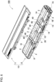
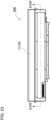
- FIG. 1 is a perspective view showing battery pack 100 according to the first exemplary embodiment
- FIG. 2 is a perspective view of battery pack 100 of FIG. 1 as obliquely viewed from below
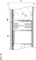
- FIG. 3 is a cross-sectional view of battery pack 100 of FIG. 1 taken along line III-III
- FIG. 4 is a sectional view of battery pack 100 of FIG. 1 taken along line IV-IV
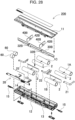
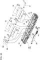
- FIG. 5 is an exploded perspective view of battery pack 100 of FIG. 1
- FIG. 6 is a perspective view showing a state of battery pack 100 of FIG. 1 from which cover 11 is removed
- FIG. 7 is a plan view of battery pack 100 of FIG.
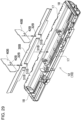
- FIG. 8 is an exploded perspective view showing a state where longitudinal partition plate 30 and lateral partition plates 40 are set in housing case 10 in FIG. 1
- FIG. 9 is an exploded perspective view showing a state where insulating thermal resistant plates 2, secondary battery cells 1, and circuit board 20 are set in battery pack 100 of FIG. 8
- Battery pack 100 houses a plurality of secondary battery cells 1 inside, and connects secondary battery cells 100 in series or in parallel to achieve a capacity increase and allow charging and discharging. Power is supplied by connecting battery pack 100 to an external device corresponding to a driving target, and discharging secondary battery cells 1.
- battery pack 100 is connected to an external device constituted by a laptop computer.
- the external device to which the battery pack of the present invention is connected is not limited to the laptop computer, but may be other electronic devices and electric devices, such as a cellular phone, a portable digital versatile disc (DVD) player, a portable car navigation system, and a portable music player, or an electric tool or an assisted bicycle, for example.
- the battery pack may be directly and detachably attached to an external device for use, or may be housed or embedded inside an external device, or may be connected via a cable or the like.
- Battery pack 100 has a box-shaped external appearance extending in one direction as shown in FIGS. 1 and 2 and other figures.
- a box-shaped main body is constituted by housing case 10, and is divided into two parts, i.e., cover 11 and case body 12, as shown in FIGS. 3 , 4 , 5 , and 6 .
- Housing case 10 includes connector 14, and connection mechanism 13 for connecting to an electric device (a laptop computer herein) corresponding to a driving target to which power is supplied using battery pack 100.
- Lock mechanism 15 may be further provided to maintain an attached state of battery pack 100 to an electric device.
- Housing case 10 is made of a material having excellent electrical insulation and thermal insulation properties, such as polycarbonate and other resins.
- each of secondary battery cells 1 is constituted by a cylindrical secondary battery cell having a cylindrical exterior can.
- Secondary battery cells 1 herein are constituted by six secondary battery cells, i.e., first secondary battery cell 1A, second secondary battery cell 1B, third secondary battery cell 1C, fourth secondary battery cell 1D, fifth secondary battery cell 1E, and six secondary battery cell 1F. Two battery rows, each constituted by three of these cells connected in series, are connected in parallel. A number and a connection form of the secondary battery cells may be freely varied.
- Each of secondary battery cells 1 having a cylindrical shape is a lithium ion secondary battery.
- each of the secondary battery cells having a cylindrical shape may be constituted by a chargeable/dischargeable secondary battery such as a nickel metal hydride battery and a nickelcadmium battery, especially a battery that generates high-temperature heat in a use state.
- secondary battery cells 1A, 1B, 1C, 1D, 1E, 1F are electrically connected to each other in series or in parallel by lead plates 21, 22, 23, 24.
- Each of lead plates 21, 22, 23, 24 is produced by bending a metal sheet having excellent conductivity.
- Lead plates 21, 22, 23, 24 are welded to electrodes on end surfaces of secondary battery cells 1A, 1B, 1C, 1D, 1E, 1F.
- total + and total - of a battery assembly constituted by secondary battery cells 1A, 1B, 1C, 1D, 1E, 1F connected to each other are connected to circuit board 20.
- a charge/discharge circuit and a protection circuit are mounted on circuit board 20.
- an intermediate potential lead wire for measuring intermediate potential, or potential of a temperature detector for detecting each temperature of secondary battery cells 1 may be connected to circuit board 20 to recognize each voltage of secondary battery cells 1.
- a thermistor or the like is used as the temperature detector.
- connector 14 is directly connected to circuit board 20, and is disposed in a vertical posture on a side surface side of housing case 10.
- battery housing spaces 16 are partitioned inside housing case 10 to house secondary battery cells 1.
- Longitudinal partition plate 30 and lateral partition plates 40 are disposed in housing case 10 to partition battery housing spaces 16.
- Longitudinal partition plate 30 extends in a longitudinal direction of housing case 10. That is, longitudinal partition plate 30 is disposed substantially parallel to side walls 17 and substantially at a center between side walls 17 to divide an internal space of housing case 10 into two parts. Side walls 17 are located on both sides extending in the longitudinal direction of housing case 10.
- Longitudinal partition plate 30 is made of a material having excellent electrical insulation and thermal insulation properties, such as mica.
- lateral partition plates 40 extend in a lateral direction of housing case 10, that is, substantially parallel to end walls 18 located at both ends of housing case 10 in the longitudinal direction, and are disposed in such positions as to divide the internal space of housing case 10 into three parts in the longitudinal direction of housing case 10 between end walls 18.
- Each of lateral partition plates 40 is made of a material having excellent electrical insulation and thermal insulation properties.
- Each of lateral partition plates 40 is preferably made of mica. Mica is highly flame-retardant and non-flammable, has an excellent electrical insulation property, and is relatively inexpensive, and therefore is suitable for a part requiring thermal insulation and electrical insulation properties.
- Slits are formed in the respective partition plates to allow longitudinal partition plate 30 lateral partition plates 40 to cross each other in right-angled postures.
- Longitudinal partition plate 30 has longitudinal side slits 32, while each of lateral partition plates 40 has lateral side slit 42.
- Each width of the slits is made slightly larger than a thickness of the other partition plate crossing the corresponding slit.
- housing case 10 is divided into six parts as shown in FIGS. 8 and 9 by combining longitudinal partition plate 30 and lateral partition plates 40 to partition battery housing spaces 16 in each of which corresponding secondary battery cell 1 is housed. Secondary battery cells 1 housed in corresponding battery housing spaces 16 formed individually are physically separated from each other. As a result, electrical insulation and thermal insulation between secondary battery cells 1 are achieved.
- one longitudinal partition plate 30 disposed in parallel to the longitudinal direction is used to divide the internal space of housing case 10 into two parts in the lateral direction.
- Two or more longitudinal partition plates may be used to divide the internal space of the housing case into three or more parts.
- two lateral partition plates 40 disposed in parallel to the lateral direction is used to divide the internal space of the housing case into three parts.
- One lateral partition plate may be used to divide the internal space of the housing case into two parts, or three or more lateral partition plates may be used to divide the internal space of the housing case into four or more parts.
- the plurality of battery housing spaces 16 are formed by dividing the internal space of housing case 10 in this manner, a number of secondary battery cells need not necessarily be equalized with a number of the battery housing spaces.
- the number of the secondary battery cells may be smaller than the number of the battery housing spaces.
- the number of secondary battery cells 1 is four even in a state where six battery housing spaces 16 are formed similarly to the first exemplary embodiment.
- first secondary battery cell 1A, second secondary battery cell 1B, third secondary battery cell 1C, and fourth secondary battery cells 1D are used as the four secondary battery cells.
- battery rows each constituted by two cells connected in series are connected to each other in parallel.
- two secondary battery cells, i.e., first secondary battery cell 1A and third secondary battery cell 1C are disposed such that end surfaces of these battery cells face each other to constitute a first battery row
- two secondary battery cells, i.e., second secondary battery cell 1B and fourth secondary battery cell 1D are disposed such that end surfaces of these battery cells face each other to constitute a second battery row.
- a number of series connections need not necessarily be two or more.
- Each of the battery rows may be constituted by one secondary battery cell and connected to each other in parallel.
- Lead plates 22, 23 are also inserted into longitudinal side slits 32 as shown in FIG. 9 .
- Longitudinal side slits 32 are therefore common slits into which lead plates 22, 23 and lateral partition plates 40 are both inserted. This configuration prevents formation of an additional gap, thereby improving safety.
- any measures should be taken to enhance safety even in a case of thermal runaway of any one of the secondary battery cells for some reasons.
- a longitudinal partition plate is disposed between secondary battery cells disposed such that side surfaces of these battery cells are adjacent to each other.
- a lead plate needs to be inserted to meet the requirement of electric connection between these secondary battery cells.
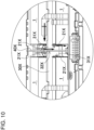
- lead slit 31X in longitudinal partition plate 30X is formed as a slit through which lead plate 21X is inserted as in a battery pack according to Comparative Example 1 shown in FIG. 10 .
- lead slit 31X becomes thicker than the lead plate in accordance with manufacturing tolerances and processing accuracy.
- a gap is produced in lead slit 31X even with the lead inserted into lead slit 31X. Therefore, if flame blows out from a side surface of one secondary battery cell as a result of thermal runaway, the flame is considered to pass through lead slit 31X and flow into a battery housing space of an adjacent secondary battery cell as indicated by arrows in FIG. 10 .
- lateral slit 32X needs to be formed in longitudinal partition plate 30X to allow lateral partition plate 40X to cross long partition plate 30X. In this case, flame may also flow from this gap.
- the slits common to lead plate 22 and lateral partition plate 40 are formed, and lead plates 22, 23 and lateral partition plates 40 are integrally inserted through the slits to reduce a gap and thereby reduce a space that may become a flame exhausting path.
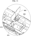
- longitudinal side slit 32 is formed on a lower side of longitudinal partition plate 30 as shown in FIG. 12 .
- Lead plate 22 and lateral partition plate 40 are inserted into longitudinal side slit 32 thus formed as shown in FIG. 13 .
- This configuration limits the gap of longitudinal side slit 32 using lead plate 22 and lateral partition plate 40, thereby reducing the flame exhausting path and improving safety as shown in FIG. 14 .
- FIG. 15A shows lead slit 31X of FIG. 10
- FIG. 15B shows longitudinal side slit 32 of FIG. 14 herein.
- longitudinal partition plate 30X is made of mica in FIG. 15A
- a width of lead slit 31X is set to D1 mm in accordance with processing accuracy of mica.
- lead plate 22 is constituted by a metal sheet made of nickel or the like
- gap D3 + D4 becomes D1 - D2 mm on an assumption that a thickness of the metal sheet is D2 mm.
- longitudinal partition plate 30 in FIG. 15B is similarly made of mica, that a width of longitudinal side slit 32 is D6 mm, and that the thickness of lead plate 22 is D2 mm.
- a gap D8 + D9 becomes D6 - D2 - D7 mm (in a case where a gap between lead plate 22 and lateral partition plate 40 is present, this gap is included in D8 + D9).
- a length of the gap D8 + D9 herein is much smaller than a length of the gap D3 + D4. Sufficient reduction of the gap in this manner reduces the flame exhausting path, thereby further decreasing a possibility of fire spread, and improving safety.
- lateral partition plate 40 thicker than lead plate 22 is overlapped and integrated with lead plate 22. This configuration produces such an advantage that lead plate 22 is stably held in longitudinal side slit 32.
- two lateral partition plates 40 are separately disposed. Even if flame blows out from an end surface of one of the secondary battery cells in this configuration, damage to another battery cell adjacent to this secondary battery cell in the end surface direction is avoidable by using two lateral partition plates 40. Furthermore, a thermal insulation effect of an air layer can be also produced by a space formed between two lateral partition plates 40. Accordingly, thermal insulation performance also improves.
- a number of lateral partition plates 40 for defining battery housing spaces 16 is adjustable according to required thermal insulation performance. Accordingly, three or more plates may be provided or only one plate may be provided. For example, only one plate is provided in the secondary exemplary embodiment described below as shown in FIGS. 24 and 25 , and other figures.
- a pair of ribs for holding longitudinal partition plate 30 are further formed on the inner surface of housing case 10. Specifically, as shown in a cross-sectional view of FIG. 3 , a pair of ribs 34 extending in the longitudinal direction are provided upright on the inner surface of case body 12 of housing case 10 at a substantially central position. Each of ribs 34 is formed integrally with case body 12 and cover 11. A lower end of longitudinal partition plate 30 is inserted between the pair of ribs 34 to hold longitudinal partition plate 30 inside housing case 10.
- an interface between the respective ribs and longitudinal partition plate 30 is filled with flame-retardant adhesive material 36.
- a gap between the ribs and longitudinal partition plate 30 is filled in this manner to avoid such a situation where flame exhaust possibly produced during thermal runaway of the secondary battery cell reaches the adjacent secondary battery cell.
- longitudinal partition plate 30 is disposed between the side surfaces of the secondary battery cells to prevent damage to the adjacent different secondary battery cell by using longitudinal partition plate 30 even when one of the secondary battery cells causes thermal runaway and blows out flame or high-pressure gas toward the side surface.
- flame is considered to leak toward an adjacent secondary battery cell through gap 35Y when gap 35Y is present at a connecting portion between ribs 34Y and longitudinal partition plate 30Y.
- a gap between ribs 34 and the lower end of longitudinal partition plate 30, and an upper end of longitudinal partition plate 30 are filled with flame-retardant adhesive material 36 to fill the gap.
- Flame-retardant adhesive material 36 may be made of silicone resin or the like.
- a temporary sealing effect is produced by filling the gap with adhesive material 36 thus provided.
- blowout of flame and high-pressure gas generally continues for a short period of approximately a few seconds. In this case, direct exposure of the adjacent secondary battery cell to flame or high-pressure gas is avoidable if strength of the flame or the high-pressure gas is reduced. Accordingly, sufficient fire spread preventing effect is expected to be achieved.
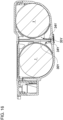
- each of the secondary battery cells is covered with insulating thermal resistant plate 2.
- Insulating thermal resistant plates 2 are provided so as to cover at least opposing regions of respective side faces of secondary battery cells 1 disposed adjacent to each other such that these side faces face each other.
- Each of insulating thermal resistant plates 2 is curved along the side surface of corresponding secondary battery cell 1. According to this configuration, each of insulating thermal resistant plates 2 is capable of covering corresponding secondary battery cell 2 along the side surface in a posture easily coming into close contact with the side surface, thereby efficiently improving a thermal insulation property in a limited space.
- Each of insulating thermal resistant plates 2 shown in FIG. 3 and other figures is curved in a U shape around a position where a pair of secondary battery cells 1 come closest to each other in a cross-sectional view.
- a flame exhaust direction can be regulated such that flame exhaust caused by secondary battery cell 1 flows not toward the side surface but toward a rear side in an up-down direction. Accordingly, safety improves.
- each of insulating thermal resistant plates 2 may contain a fibrous material.
- each of insulating thermal resistant plates 2 is constituted by a plate member made of an inorganic material. It is preferable that each of insulating thermal resistant plates 2 is made of mica. This configuration achieves high thermal resistance at low cost.
- longitudinal partition plate 30 constitutes thermal insulator 50.
- first thermal insulator 51 is provided on a side facing a side surface of the cylindrical shape of first secondary battery cell 1A on the right side, and projects to come into contact with this side surface of the cylindrical shape.
- second thermal insulator 52 is provided on a side facing a side surface of a cylindrical shape of second secondary battery cell 1B on the left side, and projects to come into contact with this side surface of the cylindrical shape. This configuration brings a partially projected portion of longitudinal partition plate 30 into contact with the side surface of the cylindrical shape of the secondary battery cell, thereby separating longitudinal partition plate 30 from the secondary battery cell to form an air layer which improves a thermal insulation property.
- battery pack 100 includes thermal insulator 50 partially projected from both surfaces of longitudinal partition plate 30.
- This thermal insulator is disposed at a position in contact with a vicinity of a top of the side surface of the cylindrical shape of secondary battery cell 1 to make distance D12 between the secondary battery cells longer than distance D11 the secondary battery cells of a configuration including no thermal insulator as shown in FIG. 19 .
- the air layer between the secondary battery cells enlarges by separation between the secondary battery cells. Accordingly, the enlarged air layer functions as a thermal insulating layer, thereby improving the thermal insulating effect between the secondary battery cells.
- this configuration allows reduction of the thickness of the longitudinal partition plate itself, thereby contributing to weight reduction of the entire battery pack.
- Thermal insulator 50 may be formed integrally with longitudinal partition plate 30, but is preferably a member separated from longitudinal partition plate 30.
- a material different from the material of the longitudinal partition plate is available to constitute the thermal insulator.
- Thermal insulator 50 is therefore allowed to be made of a material having a higher thermal insulation property than the material of longitudinal partition plate 30. Accordingly, reduction of cost and weight is achievable by providing a member exhibiting higher heat insulation not on the entire surface of longitudinal partition plate 30 but on a part of the surface.
- mica is preferably used as the material of thermal insulator 50 having an excellent thermal insulation property.
- thermal insulator 50 is a member separated from longitudinal partition plate 30, the thermal insulator is bonded to the surface of longitudinal partition plate 30. A double-sided tape or an adhesive is used for this bonding.
- thermal insulator 50 may be extended in the longitudinal direction of longitudinal partition plate 30, or may be partially cut off in the longitudinal direction. In the example of FIGS. 5 and 8 and other figures, thermal insulator 50 is cut off at the portions where the longitudinal side slits 32 are formed. In addition, the thermal insulator may be extended in a slit shape as described above, or may be parts having rectangular shapes and provided separately from each other. Even when the thermal insulator is partially provided in the longitudinal direction, the thermal insulator is capable of forming a thermal insulating layer by coming into contact with the side surface of the cylindrical secondary battery cell in contact with the thermal insulator. Moreover, the volume of the thermal insulator to be used decreases, wherefore reduction of cost and weight is achievable.
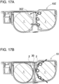
- first thermal insulator 51 and second thermal insulator 52 may be disposed such that centers of respective insulators 51 and 52 are shifted from each other in a left-right direction of longitudinal partition plate 30 in the cross-sectional view as shown in FIG. 18 .
- centers of the cross sections of left and right secondary battery cells 1 are shifted from each other in the left-right direction of longitudinal partition plate 30. Accordingly, concentration of the stresses is reduced.
- first thermal insulator 51 and second thermal insulator 52 are preferably arranged so as to partially overlap with each other in the left-right direction of longitudinal partition plate 30. In this manner, mechanical rigidity increases.
- a flame exhausting path is defined according to the first exemplary embodiment. Flame or the like exhausted from the end surface of the secondary battery cell is further exhausted from battery pack 100 through the flame exhausting path. If flame exhaust is caused in a secondary battery cell, a flow direction of this flame is difficult to predict. If a secondary battery cell is located ahead in the flow direction of the flame, thermal runaway is considered to propagate as a result of fire spread or fire catch.
- the flame exhausting path is therefore intentionally provided to reduce unintended runaway of the secondary battery cell and control a flow of flame even if flame exhaust is caused. Specifically, even if flame exhaust is caused, the flame exhausting path provided in the battery pack collects the flame exhaust at a predetermined portion of the battery pack, and discharges the flame exhaust to the outside of the battery pack.
- flame exhaust cutout 37 is formed at an upper end of longitudinal partition plate 30 as a specific flame exhausting path regulating structure.
- flame exhaust port 38 is opened on each side surface of housing case 10 in the longitudinal direction in an area corresponding to a portion between two lateral partition plates 40, that is, first lateral partition plate 40a and second lateral partition plate 40b.
- guide ribs 39 project downward from an inner surface of cover 11. A portion between an upper end and the inner surface of cover 11 constitutes upper cover gap 19.
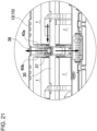
- first secondary battery cell 1A As shown in the vertical cross-sectional view of FIG. 22 , it is considered herein to prevent a situation that flame exhaust caused on the end surface of first secondary battery cell 1A, for example, flows toward third secondary battery cell 1C disposed such that the end surfaces of these cells face each other.
- flame blown out from the end surface of first secondary battery cell 1A tends to move along lead plate 22 and first lateral partition plate 40a facing the end surface, and tends to move upward or downward. While the upward movement of the flame is indicated by an arrow in FIG. 22 for convenience of explanation, the downward movement is basically similar movement.
- first lateral partition plate 40a crosses over first lateral partition plate 40a.
- most of the flame passes through one of flame exhaust ports 38 or flame exhaust cutout 37, and is discharged from the other of flame exhaust ports 38 to the outside of battery pack 100.
- the flame not discharged and left at this time advances along guide ribs 39 while changing a flame direction upward and downward, and again passes through one of flame exhaust port 38 or flame exhaust cutout 37 and is discharged from the other of flame exhaust ports 38 to the outside of battery pack 100.
- the traveling direction of the flame has already been forced to change upward and downward many times. In this case, the moving strength has been considerably lowered.
- thermal runaway may also be reduced by disposing heat absorbers 60 inside the housing case.
- each of heat absorbers 60 absorbs heat generated by the secondary battery cell causing thermal runaway in a case of thermal runaway caused by any one of the secondary battery cells inside the housing case, thereby reducing a chain of thermal runaway to the adjacent secondary battery cell.
- heat absorbers 60 are disposed in battery housing spaces 16
- efficient disposition of heat absorbers 60 is achievable inside the housing case having a limited volume without the necessity of preparing a space dedicated for heat absorbers 60.
- an excessive battery housing space is effectively utilized by disposing heat absorber 60 in the battery housing space in which the secondary battery cell is not housed.
- FIGS. 23 to 30 A battery pack including heat absorbers 60 described above is shown in FIGS. 23 to 30 as a second exemplary embodiment.
- FIG. 23 is a plan view of battery pack 200 according to the second exemplary embodiment
- FIG. 24 is a cross-sectional view taken along line XXIV-XXIV of FIG. 23
- FIG. 25 is an enlarged cross-sectional view of FIG. 24
- FIG. 26 is an exploded perspective view showing a state of battery pack 200 of FIG. 23 from which cover 11 is removed
- FIG. 27 is a plan view of battery pack 200 of FIG. 26
- FIG. 28 is an exploded perspective view of battery pack 200 of FIG. 23
- FIG. 29 is an exploded perspective view showing a state of battery pack 200 of FIG.
- FIG. 30 is an exploded perspective view showing a state of battery pack 200 of FIG. 29 where insulating thermal resistant plates 2, the secondary battery cells, and heat absorbers are disassembled. Note that parts identical to corresponding parts of the first exemplary embodiment described above are given identical reference numerals, and detailed description of these parts will be omitted where appropriate.
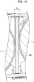
- Each of heat absorbers 60 is a metal part having a cylindrical shape which is hollow inside. This shape increases a surface area and enhances a heat absorption effect while reducing a weight of heat absorber 60.
- An aluminum pipe can be preferably used as heat absorber 60 made of metal. Aluminum has stable characteristics such as lightweight, high heat transfer property, low-cost, and no corrosion.
- heat absorber 60 is not necessarily required to have the same length as the length of the secondary battery cell, and may be shorter than the length of the secondary battery cell. This reduction of the length can reduce material cost and weight.
- the length of heat absorber 60 is appropriately set according to a required amount of heat absorption such as the capacity of the secondary battery cell to be used and the temperature at the time of heat generation.
- heat absorber 60 When heat absorbing body 60 is shortened, heat absorber 60 is fixed without movement in corresponding battery housing space 16. For example, double-sided tape or adhesive is used. When heat absorber 60 is made shorter than the secondary battery cell, heat absorber 60 is eccentrically fixed in battery housing space 16 in such a manner as to come close to different battery housing space 16 which is located adjacent to corresponding battery housing space 16 in the longitudinal direction, and houses the different secondary battery cell. By disposing heat absorber 60 close to the end surface of the secondary battery cell corresponding to a heat absorbing target, the heat absorbing effect can be effectively exerted during heat generation from the corresponding secondary battery cell.
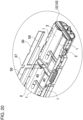
- longitudinal side slits 32B and lateral side slits 42B formed in longitudinal partition plate 30B and lateral partition plates 40B are opposite to the corresponding directions of the first embodiment as shown in FIGS. 28 and 29 , and other figures.
- longitudinal side slits 32B are formed at an upper end side of longitudinal partition plate 30B
- lateral side slit 42B is formed at a lower end side of each of lateral partition plates 40B.
- lead slits 31B through which lead plates 22, 25 are inserted are formed in longitudinal partition plate 30B separately from longitudinal side slits 32B. Lead slits 31B thus formed are provided on the lower end side of longitudinal partition plate 30B.
- Lead slits 31B and longitudinal side slits 32B are formed at the opposite edges as described above.
- This configuration eliminates the necessity of work for setting longitudinal partition plate 30B in a state where lead plates 22, 25 and lateral partition plates 40B have been set in housing case 10 in advance. Specifically, this configuration eliminates the necessity for positional alignment to allow simultaneous insertion of lead plates 22, 25 and lateral partition plates 40B into the lead slits and the longitudinal side slits at the time of setting of longitudinal partition plate 30B in housing case 10.
- either lead plates 22, 25 or lateral partition plates 40B may be initially guided to lead slit 31B to set longitudinal partition plate 30B, and then lateral partition plates 40B may be set to position only lateral side slits 42B. Workability improves by dividing the positioning work for the slits in this manner.
- the battery pack according to the present invention is suitably applicable to a chargeable/dischargeable battery pack for a battery-driven device such as a laptop computer, a cellular phone, a portable digital versatile disc (DVD) player, a portable car navigation system, a portable music player, a power tool, and an assisted bicycle.
- a battery-driven device such as a laptop computer, a cellular phone, a portable digital versatile disc (DVD) player, a portable car navigation system, a portable music player, a power tool, and an assisted bicycle.
Landscapes
- Chemical & Material Sciences (AREA)
- Chemical Kinetics & Catalysis (AREA)
- Electrochemistry (AREA)
- General Chemical & Material Sciences (AREA)
- Engineering & Computer Science (AREA)
- Manufacturing & Machinery (AREA)
- Life Sciences & Earth Sciences (AREA)
- Biophysics (AREA)
- Inorganic Chemistry (AREA)
- Computer Hardware Design (AREA)
- Battery Mounting, Suspending (AREA)
- Secondary Cells (AREA)
Claims (7)
- Bloc-batterie comprenant :une pluralité de cellules de batterie rechargeable (1) ayant chacune une forme cylindrique et connectées en série et/ou en parallèle les unes avec les autres ;un boîtier de logement (10) qui a un espace interne pour loger la pluralité de cellules de batterie rechargeable (1) ; etune plaque de séparation longitudinale (30) qui est disposée parallèle à la direction longitudinale du boîtier de logement (10) et qui sépare l'espace interne du boîtier de logement (10) en espaces de logement de batterie (16), les espaces de logement de batterie (16) logeant chacun l'une correspondante parmi la pluralité de cellules de batterie rechargeable (1),dans laquelle la pluralité de cellules de batterie rechargeable (1) est alignée en parallèle en des positions telles que les surfaces latérales des formes cylindriques se fassent mutuellement face dans l'espace interne du boîtier de logement (10), et sont séparées les unes des autres avec la plaque de séparation longitudinale (30) interposée entre la pluralité de cellules de batterie rechargeable (1),une paire de nervures (34) est disposée sur une surface intérieure du boîtier de logement (10) de manière à retenir la plaque de séparation longitudinale (30),la plaque de séparation longitudinale (30) disposée entre la paire de nervures (34) est retenue dans le boîtier de logement (10), etun espace produit quand la plaque de séparation longitudinale (30) est disposée entre la paire de nervures (34) est rempli d'un matériau adhésif ignifugeant (36).
- Bloc-batterie selon la revendication 1, comprenant en outre une plaque résistante à la chaleur isolante (2) qui a des propriétés d'isolation électrique et de résistance thermique, et qui couvre au moins une région de la surface latérale incluse dans chacune parmi la pluralité de cellules de batterie rechargeable (1) et faisant face à la surface latérale de l'une adjacente parmi la pluralité de cellules de batterie rechargeable (1).
- Bloc-batterie selon la revendication 2, dans lequel la plaque résistante à la chaleur isolante (2) est courbée le long de la surface latérale de la forme cylindrique de chacune parmi la pluralité de cellules de batterie rechargeable (1).
- Bloc-batterie selon la revendication 3, dans lequel la plaque résistante à la chaleur isolante (2) couvre chacune parmi une paire de la pluralité de cellules de batterie rechargeable (1) disposée de telle manière que les surfaces latérales des formes cylindriques soient placées mutuellement adjacentes, et est courbée autour d'une position où les deux de la paire parmi la pluralité de cellules de batterie rechargeable (1) deviennent les plus proches en vue en coupe transversale.
- Bloc-batterie selon l'une quelconque des revendications 2 à 4, dans lequel la plaque résistante à la chaleur isolante (2) contient des fibres.
- Bloc-batterie selon l'une quelconque des revendications 2 à 5, dans lequel la plaque résistante à la chaleur isolante (2) est un élément en plaque fait d'un matériau inorganique.
- Bloc-batterie selon l'une quelconque des revendications 2 à 6, dans lequel la plaque résistante à la chaleur isolante (2) est faite de mica.
Applications Claiming Priority (2)
| Application Number | Priority Date | Filing Date | Title |
|---|---|---|---|
| JP2018015674 | 2018-01-31 | ||
| PCT/JP2018/045412 WO2019150774A1 (fr) | 2018-01-31 | 2018-12-11 | Bloc-piles |
Publications (3)
| Publication Number | Publication Date |
|---|---|
| EP3748714A1 EP3748714A1 (fr) | 2020-12-09 |
| EP3748714A4 EP3748714A4 (fr) | 2021-03-31 |
| EP3748714B1 true EP3748714B1 (fr) | 2024-02-07 |
Family
ID=67478076
Family Applications (1)
| Application Number | Title | Priority Date | Filing Date |
|---|---|---|---|
| EP18903451.5A Active EP3748714B1 (fr) | 2018-01-31 | 2018-12-11 | Bloc-piles |
Country Status (5)
| Country | Link |
|---|---|
| US (1) | US11502347B2 (fr) |
| EP (1) | EP3748714B1 (fr) |
| JP (1) | JP7219724B2 (fr) |
| CN (1) | CN111566838B (fr) |
| WO (1) | WO2019150774A1 (fr) |
Families Citing this family (1)
| Publication number | Priority date | Publication date | Assignee | Title |
|---|---|---|---|---|
| DE102022004064A1 (de) | 2022-10-31 | 2024-01-25 | Mercedes-Benz Group AG | Batteriemodul und Verfahren zu seiner Montage sowie Batterie |
Family Cites Families (19)
| Publication number | Priority date | Publication date | Assignee | Title |
|---|---|---|---|---|
| JPH0680260A (ja) | 1992-05-29 | 1994-03-22 | Nec Corp | 紙葉類の供給装置 |
| JPH0680260U (ja) | 1993-04-22 | 1994-11-08 | 富士電気化学株式会社 | 集合電池 |
| JP3014293B2 (ja) * | 1995-04-18 | 2000-02-28 | インターナショナル・ビジネス・マシーンズ・コーポレイション | バッテリ・パック |
| JP3662895B2 (ja) * | 2002-05-09 | 2005-06-22 | 松下電器産業株式会社 | 電池パック |
| KR100857034B1 (ko) | 2005-03-25 | 2008-09-05 | 주식회사 엘지화학 | 난연성 접착부재를 포함하고 있는 전지 |
| JP2007027011A (ja) | 2005-07-20 | 2007-02-01 | Sanyo Electric Co Ltd | 電源装置 |
| JP4936744B2 (ja) * | 2006-02-28 | 2012-05-23 | 三洋電機株式会社 | パック電池とその製造方法 |
| JP2008218210A (ja) | 2007-03-05 | 2008-09-18 | Lenovo Singapore Pte Ltd | 電池パックおよび携帯式電子機器 |
| JP2008251472A (ja) | 2007-03-30 | 2008-10-16 | Sanyo Electric Co Ltd | パック電池 |
| WO2009040921A1 (fr) * | 2007-09-27 | 2009-04-02 | Panasonic Electric Works Co., Ltd. | Composition de résine époxyde et stratifié de préimprégné et de revêtement métallique produit à l'aide de cette composition |
| JP5269200B2 (ja) * | 2009-06-08 | 2013-08-21 | パナソニック株式会社 | 電池パック |
| CN102362388B (zh) * | 2009-11-25 | 2013-09-25 | 松下电器产业株式会社 | 电池模块 |
| KR20110126714A (ko) * | 2010-03-30 | 2011-11-23 | 파나소닉 주식회사 | 전지 팩 |
| JP2012033464A (ja) | 2010-07-02 | 2012-02-16 | Sanyo Electric Co Ltd | パック電池 |
| JP2014086342A (ja) | 2012-10-25 | 2014-05-12 | Sanyo Electric Co Ltd | 電池パックとその製造方法 |
| JP6236902B2 (ja) | 2013-06-14 | 2017-11-29 | 株式会社Gsユアサ | 蓄電装置 |
| JP2016072301A (ja) | 2014-09-26 | 2016-05-09 | 株式会社東芝 | 絶縁材、この絶縁材を用いた絶縁コイル、これらの製造方法、ならびにこの絶縁コイルを具備する装置 |
| JP6673606B2 (ja) * | 2014-10-17 | 2020-03-25 | 三洋電機株式会社 | 電池パック |
| JP6598063B2 (ja) | 2015-09-29 | 2019-10-30 | パナソニックIpマネジメント株式会社 | 電池モジュール |
-
2018
- 2018-12-11 WO PCT/JP2018/045412 patent/WO2019150774A1/fr unknown
- 2018-12-11 US US16/965,697 patent/US11502347B2/en active Active
- 2018-12-11 CN CN201880085788.7A patent/CN111566838B/zh active Active
- 2018-12-11 JP JP2019568909A patent/JP7219724B2/ja active Active
- 2018-12-11 EP EP18903451.5A patent/EP3748714B1/fr active Active
Also Published As
| Publication number | Publication date |
|---|---|
| JPWO2019150774A1 (ja) | 2021-01-14 |
| US20200358063A1 (en) | 2020-11-12 |
| US11502347B2 (en) | 2022-11-15 |
| EP3748714A4 (fr) | 2021-03-31 |
| EP3748714A1 (fr) | 2020-12-09 |
| CN111566838B (zh) | 2023-07-04 |
| CN111566838A (zh) | 2020-08-21 |
| JP7219724B2 (ja) | 2023-02-08 |
| WO2019150774A1 (fr) | 2019-08-08 |
Similar Documents
| Publication | Publication Date | Title |
|---|---|---|
| WO2020188949A1 (fr) | Module de batterie | |
| US11489218B2 (en) | Battery pack | |
| JP7335048B2 (ja) | 隣接モジュールへのガス移動を防止することができる電池モジュール | |
| JP2021504888A (ja) | 改善された冷却構造を有するバッテリーモジュール | |
| US11682804B2 (en) | Battery pack including housing case with longitudinal and lateral partition plates | |
| JP7276896B2 (ja) | 電池モジュール | |
| EP3748714B1 (fr) | Bloc-piles | |
| US11495843B2 (en) | Battery pack | |
| KR20220142853A (ko) | 배터리 팩 및 그 제조방법 | |
| WO2024004504A1 (fr) | Bloc-batterie | |
| EP4152500A1 (fr) | Module de batterie | |
| WO2022158506A1 (fr) | Bloc-batterie | |
| WO2024053278A1 (fr) | Bloc-batterie | |
| KR20220120916A (ko) | 전지 모듈 및 이를 포함하는 전지팩 | |
| KR20230109945A (ko) | 배터리 팩 |
Legal Events
| Date | Code | Title | Description |
|---|---|---|---|
| STAA | Information on the status of an ep patent application or granted ep patent |
Free format text: STATUS: THE INTERNATIONAL PUBLICATION HAS BEEN MADE |
|
| PUAI | Public reference made under article 153(3) epc to a published international application that has entered the european phase |
Free format text: ORIGINAL CODE: 0009012 |
|
| STAA | Information on the status of an ep patent application or granted ep patent |
Free format text: STATUS: REQUEST FOR EXAMINATION WAS MADE |
|
| 17P | Request for examination filed |
Effective date: 20200828 |
|
| AK | Designated contracting states |
Kind code of ref document: A1 Designated state(s): AL AT BE BG CH CY CZ DE DK EE ES FI FR GB GR HR HU IE IS IT LI LT LU LV MC MK MT NL NO PL PT RO RS SE SI SK SM TR |
|
| AX | Request for extension of the european patent |
Extension state: BA ME |
|
| A4 | Supplementary search report drawn up and despatched |
Effective date: 20210302 |
|
| RIC1 | Information provided on ipc code assigned before grant |
Ipc: H01M 50/262 20210101ALI20210224BHEP Ipc: H01M 50/213 20210101AFI20210224BHEP Ipc: H01M 50/24 20210101ALI20210224BHEP |
|
| DAV | Request for validation of the european patent (deleted) | ||
| DAX | Request for extension of the european patent (deleted) | ||
| REG | Reference to a national code |
Ref country code: DE Ref legal event code: R079 Ref document number: 602018065085 Country of ref document: DE Free format text: PREVIOUS MAIN CLASS: H01M0002100000 Ipc: H01M0050213000 Ref country code: DE Ref legal event code: R079 Free format text: PREVIOUS MAIN CLASS: H01M0002100000 Ipc: H01M0050213000 |
|
| GRAP | Despatch of communication of intention to grant a patent |
Free format text: ORIGINAL CODE: EPIDOSNIGR1 |
|
| RIC1 | Information provided on ipc code assigned before grant |
Ipc: H01M 50/289 20210101ALI20230630BHEP Ipc: H01M 50/222 20210101ALI20230630BHEP Ipc: H01M 50/262 20210101ALI20230630BHEP Ipc: H01M 50/24 20210101ALI20230630BHEP Ipc: H01M 50/213 20210101AFI20230630BHEP |
|
| STAA | Information on the status of an ep patent application or granted ep patent |
Free format text: STATUS: GRANT OF PATENT IS INTENDED |
|
| INTG | Intention to grant announced |
Effective date: 20230810 |
|
| GRAS | Grant fee paid |
Free format text: ORIGINAL CODE: EPIDOSNIGR3 |
|
| RAP3 | Party data changed (applicant data changed or rights of an application transferred) |
Owner name: SANYO ELECTRIC CO., LTD. |
|
| GRAA | (expected) grant |
Free format text: ORIGINAL CODE: 0009210 |
|
| STAA | Information on the status of an ep patent application or granted ep patent |
Free format text: STATUS: THE PATENT HAS BEEN GRANTED |
|
| RAP1 | Party data changed (applicant data changed or rights of an application transferred) |
Owner name: PANASONIC ENERGY CO., LTD. |
|
| AK | Designated contracting states |
Kind code of ref document: B1 Designated state(s): AL AT BE BG CH CY CZ DE DK EE ES FI FR GB GR HR HU IE IS IT LI LT LU LV MC MK MT NL NO PL PT RO RS SE SI SK SM TR |
|
| REG | Reference to a national code |
Ref country code: GB Ref legal event code: FG4D |
|
| REG | Reference to a national code |
Ref country code: CH Ref legal event code: EP |
|
| REG | Reference to a national code |
Ref country code: IE Ref legal event code: FG4D |
|
| REG | Reference to a national code |
Ref country code: DE Ref legal event code: R096 Ref document number: 602018065085 Country of ref document: DE |