EP3748051A1 - Flachkämmmaschine - Google Patents
Flachkämmmaschine Download PDFInfo
- Publication number
- EP3748051A1 EP3748051A1 EP20177349.6A EP20177349A EP3748051A1 EP 3748051 A1 EP3748051 A1 EP 3748051A1 EP 20177349 A EP20177349 A EP 20177349A EP 3748051 A1 EP3748051 A1 EP 3748051A1
- Authority
- EP
- European Patent Office
- Prior art keywords
- rectilinear
- combing machine
- connecting rod
- motor
- machine according
- Prior art date
- Legal status (The legal status is an assumption and is not a legal conclusion. Google has not performed a legal analysis and makes no representation as to the accuracy of the status listed.)
- Granted
Links
- 230000033001 locomotion Effects 0.000 claims abstract description 43
- 230000007246 mechanism Effects 0.000 claims abstract description 42
- 239000000835 fiber Substances 0.000 claims abstract description 38
- 238000007620 mathematical function Methods 0.000 claims abstract description 25
- 230000005540 biological transmission Effects 0.000 claims abstract description 15
- 230000000284 resting effect Effects 0.000 claims description 2
- 239000000463 material Substances 0.000 description 20
- 238000012423 maintenance Methods 0.000 description 19
- 239000004753 textile Substances 0.000 description 8
- 238000004140 cleaning Methods 0.000 description 6
- 230000006378 damage Effects 0.000 description 6
- 238000005461 lubrication Methods 0.000 description 6
- 230000002596 correlated effect Effects 0.000 description 4
- 230000007257 malfunction Effects 0.000 description 4
- 230000001360 synchronised effect Effects 0.000 description 4
- 238000013459 approach Methods 0.000 description 3
- 230000014759 maintenance of location Effects 0.000 description 3
- 238000013507 mapping Methods 0.000 description 3
- 238000012545 processing Methods 0.000 description 3
- 230000009467 reduction Effects 0.000 description 3
- 208000027418 Wounds and injury Diseases 0.000 description 2
- 238000010521 absorption reaction Methods 0.000 description 2
- 238000013461 design Methods 0.000 description 2
- 208000014674 injury Diseases 0.000 description 2
- 238000004513 sizing Methods 0.000 description 2
- 244000025254 Cannabis sativa Species 0.000 description 1
- 235000012766 Cannabis sativa ssp. sativa var. sativa Nutrition 0.000 description 1
- 235000012765 Cannabis sativa ssp. sativa var. spontanea Nutrition 0.000 description 1
- 230000001133 acceleration Effects 0.000 description 1
- 230000009471 action Effects 0.000 description 1
- 230000003213 activating effect Effects 0.000 description 1
- 230000001174 ascending effect Effects 0.000 description 1
- 230000008901 benefit Effects 0.000 description 1
- 235000009120 camo Nutrition 0.000 description 1
- 210000000085 cashmere Anatomy 0.000 description 1
- 235000005607 chanvre indien Nutrition 0.000 description 1
- 239000000356 contaminant Substances 0.000 description 1
- 125000004122 cyclic group Chemical group 0.000 description 1
- 230000001419 dependent effect Effects 0.000 description 1
- 238000000605 extraction Methods 0.000 description 1
- 230000002349 favourable effect Effects 0.000 description 1
- 239000011487 hemp Substances 0.000 description 1
- 239000012535 impurity Substances 0.000 description 1
- 230000000670 limiting effect Effects 0.000 description 1
- 238000004519 manufacturing process Methods 0.000 description 1
- 238000012986 modification Methods 0.000 description 1
- 230000004048 modification Effects 0.000 description 1
- 239000003921 oil Substances 0.000 description 1
- 238000009987 spinning Methods 0.000 description 1
- 239000010913 used oil Substances 0.000 description 1
- 239000002699 waste material Substances 0.000 description 1
Images


Classifications
-
- D—TEXTILES; PAPER
- D01—NATURAL OR MAN-MADE THREADS OR FIBRES; SPINNING
- D01G—PRELIMINARY TREATMENT OF FIBRES, e.g. FOR SPINNING
- D01G19/00—Combing machines
- D01G19/06—Details
- D01G19/14—Drawing-off and delivery apparatus
- D01G19/18—Roller, or roller and apron, devices, e.g. operating to draw-off fibres continuously
-
- D—TEXTILES; PAPER
- D01—NATURAL OR MAN-MADE THREADS OR FIBRES; SPINNING
- D01G—PRELIMINARY TREATMENT OF FIBRES, e.g. FOR SPINNING
- D01G19/00—Combing machines
- D01G19/06—Details
- D01G19/08—Feeding apparatus
-
- D—TEXTILES; PAPER
- D01—NATURAL OR MAN-MADE THREADS OR FIBRES; SPINNING
- D01G—PRELIMINARY TREATMENT OF FIBRES, e.g. FOR SPINNING
- D01G19/00—Combing machines
- D01G19/06—Details
- D01G19/26—Driving arrangements
Definitions
- the present invention relates to a rectilinear combing machine.
- rectilinear combing is an operation to which fibers of natural origin, such as linen, hemp, silk, Cashmere wool, and the like are subjected in order to improve the textile material being processed, eliminating the residual impurities and removing the fibers that are shorter than a set minimum length.
- fibers of natural origin such as linen, hemp, silk, Cashmere wool, and the like are subjected in order to improve the textile material being processed, eliminating the residual impurities and removing the fibers that are shorter than a set minimum length.
- the fibers are rendered parallel along a direction that is favorable for the subsequent spinning operations.
- a ribbon of fibers is fed in a stepwise manner toward a clamp provided with two jaws.
- the clamp by closing, blocks the ribbon proximate to the end, allowing the head of a tuft to protrude.
- the head of the tuft is combed by a so-called “circular comb", which consists of a rotating drum that has a sector provided with needles.
- a pair of counter-rotating rollers known as tearing rollers, supported by a support that can move with an alternating motion and is known as tearing carriage, approaches the clamp and pinches the combed head of the tuft. Then the tearing carriage moves away from the clamp, tearing the tuft from the ribbon.
- a so-called "tearing sleeve” may be interposed between the tearing rollers and consists of a rotating mat that is closed in a loop and is supported under tension between the lower tearing roller and a guiding roller in order to support the fibers in output from the tearing rollers.
- the tail of the tuft is combed by a so-called rectilinear comb or fixed comb.
- the rectilinear comb comprises a bar provided with a dense row of fine and pointed needles, such as to allow the passage of a small number of fibers between one needle and the next.
- the rectilinear comb moves with a substantially vertical alternating motion so as to be stationary in a noninterference region while the head of the tuft is combed, and then enters the tuft while the tearing carriage pulls it away from the clamp, so as to comb the tail of the tuft.
- the tearing carriage approaches the clamp again and the tearing rollers reverse the direction of rotation, so as to present the tails of the fibers that have just been combed to the heads of the fibers of the next tuft, so they are joined in the subsequent cycle.
- cam-based transmissions have the drawback of requiring frequent interventions for maintenance and replacement due to wear.
- cam-based transmissions generate considerable complications in relation to the lubrication steps.
- the oil used for lubrication of the cams in fact tends to drip onto the footing of the machine, capturing the textile fibers and the dirt, with consequent problems in cleaning and disposal of the used oils.
- the nip distance consists of the minimum distance between the tearing rollers and the clamp, which occurs when the tearing rollers pinch the head of the tuft.
- the nip distance is a parameter that must be adjusted as a function of the type of fiber being processed, since it determines the length of the nipped fibers.
- nip distance adjustment is normally performed manually, by loosening locking screws and adjusting adjustment screws on the basis of graduated scales provided on the machine.
- some known combing machines are provided with an actuation shaft which supports a set of cams having different profiles, which can be selected alternately in order to actuate the movement of the tearing carriage.
- This movement system has the same drawbacks mentioned above regarding the movement of the tearing carriage, particularly in relation to the need for maintenance and frequent replacements due to wear, to the need for lubrication, and to criticalities linked to the adjustment of the nip distance.
- this distance must be the smallest possible within the limits of tolerances, e.g., 1 millimeter.
- this movement is imparted by a feeder assembly which comprises an element known as Gill and an element known as needle board.
- the Gill consists of a flattened duct that is crossed by the ribbon of fibers.
- the Gill performs a back and forth alternating motion in relation to the stepwise movement that one wishes to impart to the ribbon of fibers, under the control of a cam-based transmission.
- combing machines can be provided with an actuation shaft which supports a set of cams having different profiles, which can be selected alternatively to actuate the alternating motion of the Gill.
- the needle board consists of a plate which supports multiple rows of needles.
- the needle board is pivoted to the Gill so as to follow its back and forth alternating motion and is actuated by an additional cam so as to cyclically insert/extract the needles in/from the Gill through slots provided on the latter.
- the needle board when the Gill is in the most retracted position (lower stroke limit), the needle board enters the Gill and sinks into the material. Then the Gill advances, thus entraining the material pinched inside it by the needle board, which follows the movement of the Gill.
- the needle board When the Gill reaches the most advanced position (upper stroke limit), the needle board rises, releasing the material, and then the Gill retracts to the initial position, thus entraining the needle board.
- the cam-based actuation system of the Gill has the same drawbacks mentioned above regarding the movements of the tearing carriage and of the rectilinear comb, particularly in relation to the need for maintenance and for frequent replacements due to wear and to the need for lubrication.
- the aim of the present invention is to improve the rectilinear combing machine so as to eliminate the drawbacks arising from the use of cams in terms of wear, maintenance, and cleaning in relation to cam lubrication.
- an object of the invention is to provide a tearing assembly that allows to adjust the nip distance more precisely and more reliably, with a higher degree of repeatability.
- a further object of the invention is to provide a system for the adjustment of the tearing assembly that can be controlled remotely.
- a still further object of the invention is to improve the tearing assembly so as to facilitate and increase the safety of the cleaning and maintenance operations.
- Another object of the invention is to provide a tearing assembly that is adequately locked in relation to the high dynamic forces involved, so as to prevent vibrocorrosion phenomena that might compromise the quality of the textile material and limit the lifespan of the machine.
- a further object of the invention is to provide a tearing assembly which, even in case of an electrical/electronic malfunction or power outage, cannot come into contact with the other moving elements of the combing machine, so as to avoid any collision damage.
- Another object of the invention is to provide a system for the adjustment of the rectilinear comb assembly that is more precise and reliable and has a higher degree of repeatability.
- a further object of the invention is to provide a system for the adjustment of the rectilinear comb assembly that can be remote-controlled.
- a further object of the invention is to improve the rectilinear comb assembly so as to facilitate and increase the safety of the operations for maintenance and material loading.
- Another object of the invention is to provide a rectilinear comb assembly that is blocked adequately in relation to the high dynamic forces involved, so as to prevent vibrocorrosion phenomena which might compromise the quality of the textile material and limit the lifespan of the machine.
- a further object of the invention is to provide a rectilinear comb assembly which, even in case of electrical/electronic malfunction or power outage, cannot come into contact with the other moving elements of the combing machine, so as to avoid any collision damage.
- a further object of the invention is to provide a feeder assembly that can be remote-controlled both during the steps for stroke adjustment and during the material loading and maintenance steps.
- Another object of the invention is to improve the feeder assembly so as to facilitate and increase the safety of the maintenance and material loading operations.
- a further object of the invention is to provide a feeder assembly which, even in case of an electrical/electronic malfunction or power outage, cannot come into contact with the other moving elements of the combing machine, so as to avoid any impact damage.
- a first aspect of the invention relates to a tearing assembly 10 of a rectilinear combing machine.
- a ribbon F of fibers is fed in a stepwise manner toward a clamp 12 by a feeder assembly 210.
- the feeder assembly 210 will be described in greater detail hereinafter with reference to a preferred embodiment thereof.
- the clamp 12 is conventionally provided with a lower jaw 14 and with an upper jaw 16 which open and close intermittently synchronously with the stepwise feeding of the ribbon F.
- the clamp 12 closes in a cyclic manner so as to lock the ribbon F proximate to the end, allowing the protrusion of the head of a tuft of fibers ( Figure 14 ) that will be subjected to the combing steps.
- the head of the tuft that protrudes from the clamp 12 is combed by a so-called circular comb arranged below the clamp 12, which is not described herein since it is beyond the aim and objects of the present invention.
- the circular comb conventionally consists of a rotating drum provided with a sector fitted with needles.
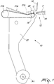
- the tearing assembly 10 which intervenes at this point of the cycle, comprises a pair of counter-rotating tearing rollers 18, 20 which are mounted on a first frame, termed tearing carriage 22.
- a mat closed in a loop 21a known as tearing sleeve, is conventionally interposed between the tearing rollers.
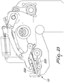
- the tearing sleeve is supported under tension between the lower tearing roller 18 and a guiding roller 21b, with the aid of a tension roller 21c which is shown only schematically in Figure 1 , and is turned by motor means (not shown).
- the tearing sleeve has the purpose of supporting the fibers that exit from the tearing rollers.
- the tearing carriage 22 oscillates about a first axis P1, under the control of first motorized transmission means, so as to move cyclically closer/away the tearing rollers 18, 20 with respect to the clamp 12.
- the tearing rollers 18, 20 pinch the freshly combed head of the tuft and then the tearing carriage 22 moves away from the clamp 12, tearing the tuft from the ribbon F.
- the tearing carriage 22 moves closer to the clamp again 12 and the tearing rollers 18, 20 reverse the direction of rotation, so as to present the tails of the fibers that have just been combed to the heads of the fibers of the next tuft, so that they so that they are joined in the subsequent cycle.
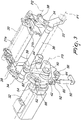
- the first motorized transmission means that actuate the alternating motion of the tearing carriage 22 comprise a first connecting rod-crank mechanism 30, which is connected to the tearing carriage by means of linkages 33 and is actuated by a first motor 32 that is controlled electronically, preferably in terms of position, according to a predetermined mathematical function.
- a brushless synchronous motor driven by means of an encoder or resolver.
- the linkages 33 comprise first lever means, preferably a first pair of levers 34 which are integral with a first actuation shaft 36 that is pivoted to the structure (not shown) of the combing machine.
- the levers of the first pair 34 are functionally connected to the opposite sides of the tearing carriage 22 by virtue of connecting rod means, preferably a pair of connecting rods 38, which are pivoted to the tearing carriage 22 about a second axis P2.
- the first connecting rod-crank mechanism 30 acts on additional lever means, preferably a third lever 39 which is integral with the first actuation shaft 36, so as to make the latter rotate through a few degrees with an alternating motion.
- the first connecting rod-crank mechanism 30 is provided by means of a first eccentric pivot 40, which is integral with the driving shaft 42 of the first motor 32 and acts as a crank, and a first connecting rod 44 which has an end fitted on the first eccentric pivot 40 and the opposite end pivoted to the third lever 39.
- the mathematical function that controls the movement of the first motor 32 is performed within the arc of one full rotation, i.e., a rotation through 360°, of the driving shaft 42, without ever reversing the direction of rotation.
- the tearing assembly 10 comprises nip distance adjustment means which can be activated remotely.
- the first motor 32 is fixed to a first support 48, which is pivoted to the structure of the combing machine parallel to the motor axis about a third axis P3, and can rotate in preselected angular positions under the control of a first electronically controlled actuator 50.
- the adjustment of the position of the first support 48 about the third axis P3 is reflected, by means of the first connecting rod-crank mechanism 30 and the linkages 33, in an adjustment of the position of the tearing carriage 22 about the first axis P1 and accordingly of the nip distance.
- the first support 48 is normally locked by means of a pair of pressurized fluid-operated actuators, preferably first hydraulic jacks 52, 54.
- the first hydraulic jacks 52, 54 have stems 56, 58 which are inserted in respective arc-like slots 60, 62 formed on the first support 48 about the third axis P3 and support respective washers 64, 66 at the ends.
- the first support 48 remains clamped in a sandwich-like manner between the body of the first jacks 52, 54 and the washers 64, 66.
- the rule of motion of the tearing carriage 22 is given by the mathematical sum of the typical sinusoidal function of connecting rod-crank mechanisms with the mathematical function that controls the rotation of the first motor 32.
- the mathematical function is programmed so as to manage the speed/position curve that the tearing assembly must follow in every step of its stroke, with particular attention in the tearing step, on the basis of the length of the fibers to be processed, of the type of material, of the contaminants and of the waste fibers that must be removed from the material.
- the mathematical function is variable as a function of the geometries and the mapping of the machine, and must be designed so as to avoid collisions with the other elements of the machine and optimize cycle times. Programming of the mathematical function is per se within the normal knowledge of the person skilled in the art and therefore is not discussed in detail herein.
- the chart of Figure 5 plots a mathematical function that establishes a relationship between the phase and the actuation axis and can be used to control the movement of the tearing assembly 10 according to the invention.
- Remote control allows a single operator who is specialized in the processing of the textile fiber to control multiple machines from a centralized control station without having to leave his post and without requiring specific mechanical knowledge.
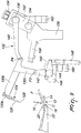
- a further aspect of the invention relates to the rectilinear comb assembly 110 of the rectilinear combing machine. For the sake of simplicity, only a portion of the latter is shown in Figures 7-9 .
- the rectilinear comb assembly 110 has the purpose of combing the tail C of the tuft while the tearing carriage 22 moves away from the clamp 12.
- the rectilinear comb assembly 110 comprises an element, known as rectilinear comb 124, which comprises a bar 126 provided with a densely packed row of fine and pointed needles 128, such as to allow the passage of a small number of fibers between one needle and the next.
- rectilinear comb 124 which comprises a bar 126 provided with a densely packed row of fine and pointed needles 128, such as to allow the passage of a small number of fibers between one needle and the next.
- the rectilinear comb 124 moves with an alternating ascending and descending motion that is synchronized with respect to the other components of the combing machine, under the control of second motorized transmission means, between a resting position, which does not interfere with the fibers while the head of the tuft is being combed, and an operative position which interferes with the tuft, while it is inserted in a drawing relationship between the two tearing rollers 18, 20, so as to comb the tail C of the tuft ( Figure 8 ).
- the second motorized transmission means comprises a second frame 130, to which the rectilinear comb 124 is fixed, which is pivoted about a third axis P3 ( Figure 7 ), and swings about said axis under the control of a second connecting rod-crank mechanism 132 which acts on the second frame 130 at a fourth axis P4; the second connecting rod-crank mechanism 132 is actuated by a second motor which 134 which is controlled electronically, preferably in terms of position, according to a predetermined mathematical function.
- the second frame 130 comprises:
- the second connecting rod-crank mechanism is provided by means of two first eccentric crowns 136, which are provided on a second actuation shaft 138 actuated by the second motor 134 and act as a crank, and a pair of second parallel connecting rods 140, each of which has an end that is pivoted to a respective one of the first arms 130a about the fourth axis P4, and the opposite end fitted on a respective one of the first eccentric crowns 136.
- the second actuation shaft 138 is connected directly and coaxially to the driving shaft (not shown) of the second motor 134.
- the second actuation shaft 138 actuated by the second motor 134 is controlled so as to perform the mathematical function over the arc of a complete 360° rotation without ever reversing the direction of rotation.
- the rectilinear comb assembly 110 comprises adjustment means which can be activated remotely in order to vary the position of the third axis P3 and of the second actuation shaft 138 in order to adjust the distance of the rectilinear comb 124 from the tearing rollers 18, 20 as a function of the nip distance variations.
- each one of the branches 130c is pivoted to the end of a fourth lever 142 about the third axis P3.
- the fourth lever 142 protrudes integrally from a first pivot 144 which is supported rotatably by a second support 146 which is integral with the structure of the machine.
- the first pivot 144 can rotate in preselected angular positions under the control of a second actuator 148 which is controlled electronically and acts on a fifth lever 150 which is integral with the first pivot 144.
- the second actuation shaft 138 is supported at its ends by a pair of sixth levers 152, which protrude integrally from a second pivot 154 which is supported rotatably by a pair of third supports 156 which are integral with the structure of the machine.
- the second pivot 154 can rotate in preselected angular positions under the control of a third actuator 158 that is controlled electronically and acts on one of the sixth levers 152.
- the second actuator 148 and the third actuator 158 are actuated so as to move respectively the third axis P3 and the second actuation shaft 138 in the same direction, toward or away from the tearing rollers 18, 20 depending on the nip distance variation.
- the second support 146 of the first pivot 144 and the third supports 156 of the second pivot 154 are kept locked by means of respective pressurized fluid-operated actuation means, preferably respective second hydraulic jacks 160, 162.
- the rule of motion of the rectilinear comb 124 is given by the mathematical sum of the typical sinusoidal function of connecting rod-crank mechanisms with the mathematical function that controls the rotation of the second motor 134.
- the mathematical function is programmed so as to manage the step of combing the tail as a function of the material to be processed and so as to avoid collisions with the other elements of the machine and optimize cycle times.
- the chart of Figure 10 shows a mathematical function which establishes a relationship between the phase and the actuation axis, and can be used to control the movement of the rectilinear comb assembly 110 according to the invention.
- the distance of the rectilinear comb 124 from the tearing rollers 18, 20 can be adjusted remotely by actuating the second actuator 148 and the third actuator 158.
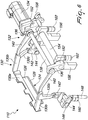
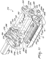
- a further aspect of the invention relates to the feeder assembly 210, which, as mentioned previously, has the purpose of feeding in a stepwise manner the ribbon F of fibers (shown only in Figure 14 ) toward the clamp 12.
- the feeder assembly 210 comprises a perforated flattened duct, per se known as Gill 220, which is adapted to be crossed by the ribbon of fibers F, and a plate provided with multiple rows of needles 221, per se known as needle board 222.
- the Gill 220 is fixed to an active end 224a of a third frame 224, and is supported slidingly by the lower jaw 14 by virtue of guiding means 225 ( Figure 14 ) located proximate to the operative end 224a.
- the third frame 224 performs a back and forth alternating motion in relation to the stepwise movement that one wishes to impart to the ribbon of fibers, under the control of first actuation means 226 which act at an actuation end 224b that is opposite the operative end 224a.
- the third frame 224 comprises two second parallel arms 224p which protrude away from the opposite sides of the Gill 220.
- the needle board 222 is fixed to a fourth frame 228 which is pivoted to the third frame 224 about a fifth axis P5 ( Figure 11 ).
- the needle board 222 is adapted to be inserted/extracted cyclically in/from the Gill 220 with its needles 221 under the control of second actuation means 230 ( Figures 12 , 13 , 15 and 16 ).
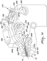
- the first actuation means 226, which actuate the Gill 220 comprise a crank mechanism actuated by a third motor 234 (shown only in Figure 17 ) and controlled electronically, preferably in terms of position, on the basis of a first predetermined mathematical function;
- the second actuation means 230, which actuate the needle board 222 comprise a third connecting rod-crank mechanism actuated by a fourth motor 238 which also is controlled electronically, preferably in terms of position, on the basis of a second mathematical function that is correlated with the first one.
- crank mechanism comprises a third actuation shaft 240 actuated by the third motor 234, which is provided with two second eccentric crowns 242, which act as a crank, and engage rotatably respective annular seats 244 provided at the actuation end 224b of the third frame 224, i.e., at the free ends of the second parallel arms 224p.
- the third connecting rod-crank mechanism comprises a fourth actuation shaft 248 which integrally supports two cranks 250, and a pair of third connecting rods 252, each of which has an end that is pivoted to the fourth frame 228 about a sixth axis P6 ( Figure 11 ) and the opposite end pivoted to a respective one of the two cranks 250.
- the fourth actuation shaft 248 is activated by the fourth motor 238, preferably by means of third transmission means 253.
- the third transmission means 253 comprise a seventh lever 254, which is fitted freely on the fourth actuation shaft 248 and is subjected to the action of a fourth connecting rod-crank mechanism 256 actuated by the fourth motor 238.
- the fourth connecting rod-crank mechanism comprises a fourth connecting rod 258, which has one end pivoted to the free end of the seventh lever 254 and an opposite end pivoted on a second eccentric pivot 260 ( Figures 14 and 15 ), acting as a crank, which is integral with the driving shaft of the fourth motor 238.
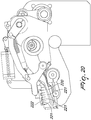
- the seventh lever 254 is provided with a first tooth 262 which, when the seventh lever 254 is turned in the direction for lifting the needle board 222, i.e., in the direction indicated by the arrow R in Figure 15 , engages one of the two cranks 250, pushing it to rotate in the same direction.
- the rise of the needle board 222 is contrasted by a traction spring 264, which, in normal operating conditions, pushes the needle board 222 against the Gill 220.
- the needle board 222 is provided with rubber pads 265a adapted to abut against respective abutments 265b which are integral with the Gill 222 ( Figures 11 and 14 ).
- the traction spring 264 acts between an eighth lever 266, which is integral with the fourth actuation shaft 248, and a ninth lever 270, which is pivoted to the structure 272 of the machine.
- the ninth lever 270 is articulated, by means of a third arm 274, to a tenth lever 276, which is fitted freely on the fourth actuation shaft 248 to the side of the eight lever 266.
- the eighth lever 266 is provided with a second tooth 278 ( Figures 12 and 13 ) which, when the tenth lever 276 is turned in the direction for lifting the needle board 222, i.e., in the direction indicated by the arrow N in Figure 12 , is engaged by the tenth lever 276, pushing the eighth lever 266 in the same direction.
- the third arm 274 can move, under the actuation of a pneumatic actuator 280, between
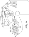
- a safety system 281 ( Figure 17 ) adapted to prevent the risk of collisions between the needle board 222 and the upper jaw 16 of the clamp 12 in case of loss of control of the third motor 234.
- the safety system comprises a retention element 282 which protrudes radially and integrally from the third actuation shaft 240, and a rocker 284, which is pivoted centrally to the structure 272 of the machine.
- a first end 284a of the rocker 284 supports an abutment wheel 286 which is arranged along the trajectory of the retention element 282.
- a second end 284b of the rocker 284 is pivoted to a fifth connecting rod-crank mechanism 288, which is functionally connected to a fifth actuation shaft 290 of the upper jaw 16, so that the rocker 284 oscillates uniquely in relation to the movements of the upper jaw 16.
- the fifth connecting rod-crank mechanism 288 comprises an eleventh lever 292 which is integral with the fifth actuation shaft 290 of the upper jaw 16 and is connected to the second end 284b of the rocker 284 by means of a fifth connecting rod 294.
- the retention element 282 and the rocker 284 are arranged so as to come into contact only in case of loss of control of the third motor 234, before the needle board 222 (which is arranged above the Gill 220) collides with the upper jaw 16, so as to prevent the collision.
- Figures 18-23 show in succession the feeding steps performed by the feeder assembly according to the invention.
- a first step ( Figure 19 ) the clamp 12 rotates downward about a seventh axis P7 and at the same time the upper jaw 16 begins to close onto the lower jaw 14. Simultaneously, the Gill 220 and the needle board 220 advance, under the control of the respective actuation means, so as to keep constant the distance L1 between the Gill 220 and the lower jaw 14. The upper jaw 16 closes completely onto the lower jaw 14 at the end of the downward rotation of the clamp 12.
- the needle board 222 rises under the control of the two connecting rod-crank mechanisms, so as to extract its needles 221 from the Gill 220 and release the material.
- a third step under the control of the crank mechanism, the Gill 220 retracts by a stroke Lc that can be set by the user, and entrains the needle board 222, which is pivoted to the Gill 220 about the fifth axis P5.
- the clamp 12 begins to rise and open, while the Gill 220 and the needle board 222 start to advance, under the control of the respective actuation means, the position of the needle board 222 being compensated by the respective actuation means so as to ensure correct contact with the Gill 220 ( Figure 23 ).
- the mathematical functions are programmed so as to manage the strokes of the Gill and of the needle board, with the possibility of fine adjustment, e.g., as a function of the material to be processed.
- the stroke of the needle board 222 in operative conditions is delimited by the maximum stroke of the third connecting rod-crank mechanism, which is chosen appropriately so as to avoid any collisions with the other elements of the machine, even if control of the fourth motor 238 is lost accidentally.
- the safety system 281 described above prevents the risk of collisions between the needle board 222 and the upper jaw 16 in case of loss of control of the third motor 234.
- the pneumatic actuator 280 is actuated so as to completely lift the needle board 222 in the manner described above.
- Figures 24 and 25 show two mathematical functions that establish a relationship between the phase and the actuation axis respectively of the third motor 234 and of the fourth motor 238.
- Figure 24 shows the possibility to adjust the rule of motion of the Gill 220 between a maximum feeding stroke and a minimum feeding stroke.
- the actuation systems of the tearing assembly and preferably of the rectilinear comb assembly and of the feeder assembly allow to overcome the problems that affect known systems based on cams in relation to wear, maintenance and cleaning with reference to cam lubrication operations.
- the connecting rod-crank mechanism allows to limit considerably the energy absorption and consequently control the motor with greater precision during the reversal steps, by virtue of the fact that, as known, in the top dead center and bottom dead center of the mechanism the actuation torques on the actuation shaft are nil, while the effort on the foot of the connecting rod is maximum.
- the described system also allows to limit the size of the motors and consequently reduce manufacturing and operating costs.
- the system for adjusting the nip distance in the tearing assembly being actuated by an electronically controlled actuator, is more precise and reliable, with a much higher degree of repeatability with respect to the manual solutions of the background art.
- the rectilinear comb assembly provided according to what has been described above further contributes to achieving the aim and objects of the invention, since it facilitates and increases the safety also of the operations for material loading and maintenance.
- the rectilinear comb 124 can be raised (even remotely) by rotating (clockwise in Figures 7 and 9 ) the sixth levers 152 about the axis of the second pivot 154 and consequently the second frame 130 by means of the second connecting rods 140 about the third axis P3.
- Remote control allows a single operator who is specialized in the processing of the textile fiber to control multiple machines from a centralized control station without having to leave his post and without requiring specific mechanical knowledge.
- the adjustment system of the rectilinear comb assembly being actuated by electronically controlled actuators, is more precise and more reliable, with a high degree of repeatability with respect to the manual solutions of the background art.
- the feeder assembly also can be remotely controlled by a single operator specialized in textile fiber processing, both during the stroke adjustment steps and in the material loading and maintenance steps.
- the operator can control multiple machines from a centralized control station without having to leave his post and without requiring specific mechanical knowledge.
- the Gill stroke adjustment system being controlled electronically, is much more precise and more reliable, with a high degree of repeatability with respect to the manual solutions of the background art.
- actuation systems of the tearing assembly, of the rectilinear comb assembly and of the feeder assembly are configured so as to prevent contact between the moving elements of the combing machine even in case of electrical/electronic malfunction or power outage, so as to avoid possible collision damage.
- crank of the connecting rod-crank mechanism is provided by means of an eccentric pivot that is integral with the driving shaft, it is evident that with different geometries and dimensions it might consist of an actual crank shaped like a lever.
- crank and the connecting rod of the actuation mechanism might of course be duplicated.
- the connecting rod-crank mechanism in the embodiment described herein, has some "duplicated" elements (e.g., double connecting rod 140, double eccentric crown 136, etc.) merely for constructive/design reasons related to the dimensions and geometry of said elements.
- this aspect is entirely irrelevant and might be avoided by sizing differently said elements or by varying their geometry.
- crank of the connecting rod-crank mechanism of the rectilinear comb assembly is provided by means of an actuation shaft provided with eccentric crowns, it is evident that with different geometries and dimensions they might consist of actual cranks shaped like a lever.
- crank mechanism and the connecting rod-crank mechanism in the embodiment described herein have some elements which are "duplicated" merely for constructive/design reasons linked to the dimensions and geometry of said elements. However, from the functional standpoint this aspect is entirely irrelevant and might be avoided by sizing differently said elements or by varying their geometry.
- cranks are provided by means of an actuation shaft provided with eccentric crowns or eccentric pivots, it is evident that with different geometries and dimensions they might consist of actual cranks shaped like a lever.
Landscapes
- Engineering & Computer Science (AREA)
- Textile Engineering (AREA)
- Preliminary Treatment Of Fibers (AREA)
Applications Claiming Priority (3)
| Application Number | Priority Date | Filing Date | Title |
|---|---|---|---|
| IT201900008070 | 2019-06-05 | ||
| IT102019000008712A IT201900008712A1 (it) | 2019-06-12 | 2019-06-12 | Macchina pettinatrice rettilinea munita di gruppo strappatore perfezionato |
| IT102019000011706A IT201900011706A1 (it) | 2019-07-15 | 2019-07-15 | Macchina pettinatrice rettilinea munita di gruppo di alimentazione perfezionato |
Publications (2)
| Publication Number | Publication Date |
|---|---|
| EP3748051A1 true EP3748051A1 (de) | 2020-12-09 |
| EP3748051B1 EP3748051B1 (de) | 2022-03-09 |
Family
ID=70857119
Family Applications (1)
| Application Number | Title | Priority Date | Filing Date |
|---|---|---|---|
| EP20177349.6A Active EP3748051B1 (de) | 2019-06-05 | 2020-05-29 | Flachkämmmaschine |
Country Status (2)
| Country | Link |
|---|---|
| EP (1) | EP3748051B1 (de) |
| CN (1) | CN112048786A (de) |
Citations (7)
| Publication number | Priority date | Publication date | Assignee | Title |
|---|---|---|---|---|
| US1816644A (en) * | 1928-11-21 | 1931-07-28 | Gegauff Charles | Combing machine |
| US4041573A (en) * | 1974-06-04 | 1977-08-16 | Sant'andrea Novara Officine Meccaniche E Fonderie S.P.A. | Machine for combing and grading textile fibers |
| DE19509209A1 (de) * | 1994-04-07 | 1995-10-12 | Spinnereimaschinenbau Leisnig | Anordnung zum synchronisierten Antreiben mehrerer Achsen an Kämmaschinen |
| EP0735167A2 (de) * | 1995-03-27 | 1996-10-02 | Gerhard Dr. Mandl | Kämmaschine |
| EP0764730A1 (de) * | 1995-09-20 | 1997-03-26 | SANT'ANDREA NOVARA S.p.A. | Verfahren und Kämmaschine zum Kämmen von Textilfasern |
| FR2851261A1 (fr) * | 2003-03-12 | 2004-08-20 | Sant Andrea Novara Spa | Peigneuse rectiligne a reglage perfectionne de l'ecartement |
| FR2861092A1 (fr) * | 2003-10-21 | 2005-04-22 | Schlumberger Cie N | Peigneuse rectiligne |
Family Cites Families (2)
| Publication number | Priority date | Publication date | Assignee | Title |
|---|---|---|---|---|
| WO2008011734A1 (de) * | 2006-07-25 | 2008-01-31 | Maschinenfabrik Rieter Ag | Kämmmaschine |
| EP2108720B1 (de) * | 2008-04-11 | 2011-06-15 | Maschinenfabrik Rieter Ag | Vorrichtung zur Bildung eines gekämmten Faservlieses |
-
2020
- 2020-05-29 EP EP20177349.6A patent/EP3748051B1/de active Active
- 2020-06-05 CN CN202010506048.5A patent/CN112048786A/zh active Pending
Patent Citations (7)
| Publication number | Priority date | Publication date | Assignee | Title |
|---|---|---|---|---|
| US1816644A (en) * | 1928-11-21 | 1931-07-28 | Gegauff Charles | Combing machine |
| US4041573A (en) * | 1974-06-04 | 1977-08-16 | Sant'andrea Novara Officine Meccaniche E Fonderie S.P.A. | Machine for combing and grading textile fibers |
| DE19509209A1 (de) * | 1994-04-07 | 1995-10-12 | Spinnereimaschinenbau Leisnig | Anordnung zum synchronisierten Antreiben mehrerer Achsen an Kämmaschinen |
| EP0735167A2 (de) * | 1995-03-27 | 1996-10-02 | Gerhard Dr. Mandl | Kämmaschine |
| EP0764730A1 (de) * | 1995-09-20 | 1997-03-26 | SANT'ANDREA NOVARA S.p.A. | Verfahren und Kämmaschine zum Kämmen von Textilfasern |
| FR2851261A1 (fr) * | 2003-03-12 | 2004-08-20 | Sant Andrea Novara Spa | Peigneuse rectiligne a reglage perfectionne de l'ecartement |
| FR2861092A1 (fr) * | 2003-10-21 | 2005-04-22 | Schlumberger Cie N | Peigneuse rectiligne |
Also Published As
| Publication number | Publication date |
|---|---|
| CN112048786A (zh) | 2020-12-08 |
| EP3748051B1 (de) | 2022-03-09 |
Similar Documents
| Publication | Publication Date | Title |
|---|---|---|
| US7073540B2 (en) | Needle loom with automatic change of the weft thread | |
| EP3748051A1 (de) | Flachkämmmaschine | |
| UA121040C2 (uk) | Круглов'язальна машина для виготовлення трикотажних, панчішно-шкарпеткових або їм подібних виробів, споряджена пристроєм приводу платин | |
| EP2800829B1 (de) | Vorrichtung zur herstellung einer vertieften gewebeleiste auf schützenlosen webmaschinen | |
| US4256147A (en) | Weaving loom | |
| US7412851B2 (en) | Device to improve the yarn threading of the thread guides for warp linear knitting machines | |
| JPH03227439A (ja) | 編機のプランジャ針制御装置 | |
| RU2143019C1 (ru) | Текстильная машина для изготовления текстильных изделий из нитей | |
| SU617019A3 (ru) | Ремизоподъемна каретка к ткацкому станку | |
| DE19836453C1 (de) | Verfahren zum Bilden erster und zweiter Florhöhen beim Weben von Frottiergewebe und Webmaschine zur Durchführung des Verfahrens | |
| IT201900011706A1 (it) | Macchina pettinatrice rettilinea munita di gruppo di alimentazione perfezionato | |
| EP0805885B1 (de) | Vorrichtung zum vertikalen spannen vom gestrick an einer automatischen strickmaschine, insbesondere an einer flachstrickmaschine | |
| RU70897U1 (ru) | Привод ремизных рам ткацкого станка для производства тяжелых технических тканей | |
| EP3865610A1 (de) | Finnisseur für spinnverfahren mit einer vorgarnwickelanordnung | |
| JPS628533B2 (de) | ||
| US2865405A (en) | Method and means for actuating a thread clamp in textile machinery | |
| WO2004018756A1 (en) | Takedown unit for circular knitting machine | |
| US3060975A (en) | Method and means for scanning a pattern card of a dobby | |
| US2655696A (en) | Combing machine of the rectilinear type | |
| US3771571A (en) | Synchronized reading devices for looms | |
| EP0525490A1 (de) | Nockenschaftmaschine für Webstühle | |
| US3101749A (en) | Pattern card mechanism for a dobby | |
| IT201900008712A1 (it) | Macchina pettinatrice rettilinea munita di gruppo strappatore perfezionato | |
| US2030944A (en) | Fabric take-off mechanism for knitting machines | |
| SU1743363A3 (ru) | Устройство управлени четырехцветным механизмом образовани рисунка по утку к ткацкому станку с зажимными челноками |
Legal Events
| Date | Code | Title | Description |
|---|---|---|---|
| PUAI | Public reference made under article 153(3) epc to a published international application that has entered the european phase |
Free format text: ORIGINAL CODE: 0009012 |
|
| STAA | Information on the status of an ep patent application or granted ep patent |
Free format text: STATUS: THE APPLICATION HAS BEEN PUBLISHED |
|
| AK | Designated contracting states |
Kind code of ref document: A1 Designated state(s): AL AT BE BG CH CY CZ DE DK EE ES FI FR GB GR HR HU IE IS IT LI LT LU LV MC MK MT NL NO PL PT RO RS SE SI SK SM TR |
|
| AX | Request for extension of the european patent |
Extension state: BA ME |
|
| STAA | Information on the status of an ep patent application or granted ep patent |
Free format text: STATUS: REQUEST FOR EXAMINATION WAS MADE |
|
| 17P | Request for examination filed |
Effective date: 20201228 |
|
| RBV | Designated contracting states (corrected) |
Designated state(s): AL AT BE BG CH CY CZ DE DK EE ES FI FR GB GR HR HU IE IS IT LI LT LU LV MC MK MT NL NO PL PT RO RS SE SI SK SM TR |
|
| GRAP | Despatch of communication of intention to grant a patent |
Free format text: ORIGINAL CODE: EPIDOSNIGR1 |
|
| STAA | Information on the status of an ep patent application or granted ep patent |
Free format text: STATUS: GRANT OF PATENT IS INTENDED |
|
| INTG | Intention to grant announced |
Effective date: 20211026 |
|
| GRAS | Grant fee paid |
Free format text: ORIGINAL CODE: EPIDOSNIGR3 |
|
| GRAA | (expected) grant |
Free format text: ORIGINAL CODE: 0009210 |
|
| STAA | Information on the status of an ep patent application or granted ep patent |
Free format text: STATUS: THE PATENT HAS BEEN GRANTED |
|
| AK | Designated contracting states |
Kind code of ref document: B1 Designated state(s): AL AT BE BG CH CY CZ DE DK EE ES FI FR GB GR HR HU IE IS IT LI LT LU LV MC MK MT NL NO PL PT RO RS SE SI SK SM TR |
|
| REG | Reference to a national code |
Ref country code: CH Ref legal event code: EP Ref country code: AT Ref legal event code: REF Ref document number: 1474231 Country of ref document: AT Kind code of ref document: T Effective date: 20220315 |
|
| REG | Reference to a national code |
Ref country code: IE Ref legal event code: FG4D |
|
| REG | Reference to a national code |
Ref country code: DE Ref legal event code: R096 Ref document number: 602020002120 Country of ref document: DE |
|
| REG | Reference to a national code |
Ref country code: LT Ref legal event code: MG9D |
|
| REG | Reference to a national code |
Ref country code: NL Ref legal event code: MP Effective date: 20220309 |
|
| PG25 | Lapsed in a contracting state [announced via postgrant information from national office to epo] |
Ref country code: SE Free format text: LAPSE BECAUSE OF FAILURE TO SUBMIT A TRANSLATION OF THE DESCRIPTION OR TO PAY THE FEE WITHIN THE PRESCRIBED TIME-LIMIT Effective date: 20220309 Ref country code: RS Free format text: LAPSE BECAUSE OF FAILURE TO SUBMIT A TRANSLATION OF THE DESCRIPTION OR TO PAY THE FEE WITHIN THE PRESCRIBED TIME-LIMIT Effective date: 20220309 Ref country code: NO Free format text: LAPSE BECAUSE OF FAILURE TO SUBMIT A TRANSLATION OF THE DESCRIPTION OR TO PAY THE FEE WITHIN THE PRESCRIBED TIME-LIMIT Effective date: 20220609 Ref country code: LT Free format text: LAPSE BECAUSE OF FAILURE TO SUBMIT A TRANSLATION OF THE DESCRIPTION OR TO PAY THE FEE WITHIN THE PRESCRIBED TIME-LIMIT Effective date: 20220309 Ref country code: HR Free format text: LAPSE BECAUSE OF FAILURE TO SUBMIT A TRANSLATION OF THE DESCRIPTION OR TO PAY THE FEE WITHIN THE PRESCRIBED TIME-LIMIT Effective date: 20220309 Ref country code: BG Free format text: LAPSE BECAUSE OF FAILURE TO SUBMIT A TRANSLATION OF THE DESCRIPTION OR TO PAY THE FEE WITHIN THE PRESCRIBED TIME-LIMIT Effective date: 20220609 |
|
| REG | Reference to a national code |
Ref country code: AT Ref legal event code: MK05 Ref document number: 1474231 Country of ref document: AT Kind code of ref document: T Effective date: 20220309 |
|
| PG25 | Lapsed in a contracting state [announced via postgrant information from national office to epo] |
Ref country code: LV Free format text: LAPSE BECAUSE OF FAILURE TO SUBMIT A TRANSLATION OF THE DESCRIPTION OR TO PAY THE FEE WITHIN THE PRESCRIBED TIME-LIMIT Effective date: 20220309 Ref country code: GR Free format text: LAPSE BECAUSE OF FAILURE TO SUBMIT A TRANSLATION OF THE DESCRIPTION OR TO PAY THE FEE WITHIN THE PRESCRIBED TIME-LIMIT Effective date: 20220610 Ref country code: FI Free format text: LAPSE BECAUSE OF FAILURE TO SUBMIT A TRANSLATION OF THE DESCRIPTION OR TO PAY THE FEE WITHIN THE PRESCRIBED TIME-LIMIT Effective date: 20220309 |
|
| PG25 | Lapsed in a contracting state [announced via postgrant information from national office to epo] |
Ref country code: NL Free format text: LAPSE BECAUSE OF FAILURE TO SUBMIT A TRANSLATION OF THE DESCRIPTION OR TO PAY THE FEE WITHIN THE PRESCRIBED TIME-LIMIT Effective date: 20220309 |
|
| PG25 | Lapsed in a contracting state [announced via postgrant information from national office to epo] |
Ref country code: SM Free format text: LAPSE BECAUSE OF FAILURE TO SUBMIT A TRANSLATION OF THE DESCRIPTION OR TO PAY THE FEE WITHIN THE PRESCRIBED TIME-LIMIT Effective date: 20220309 Ref country code: SK Free format text: LAPSE BECAUSE OF FAILURE TO SUBMIT A TRANSLATION OF THE DESCRIPTION OR TO PAY THE FEE WITHIN THE PRESCRIBED TIME-LIMIT Effective date: 20220309 Ref country code: RO Free format text: LAPSE BECAUSE OF FAILURE TO SUBMIT A TRANSLATION OF THE DESCRIPTION OR TO PAY THE FEE WITHIN THE PRESCRIBED TIME-LIMIT Effective date: 20220309 Ref country code: PT Free format text: LAPSE BECAUSE OF FAILURE TO SUBMIT A TRANSLATION OF THE DESCRIPTION OR TO PAY THE FEE WITHIN THE PRESCRIBED TIME-LIMIT Effective date: 20220711 Ref country code: ES Free format text: LAPSE BECAUSE OF FAILURE TO SUBMIT A TRANSLATION OF THE DESCRIPTION OR TO PAY THE FEE WITHIN THE PRESCRIBED TIME-LIMIT Effective date: 20220309 Ref country code: EE Free format text: LAPSE BECAUSE OF FAILURE TO SUBMIT A TRANSLATION OF THE DESCRIPTION OR TO PAY THE FEE WITHIN THE PRESCRIBED TIME-LIMIT Effective date: 20220309 Ref country code: CZ Free format text: LAPSE BECAUSE OF FAILURE TO SUBMIT A TRANSLATION OF THE DESCRIPTION OR TO PAY THE FEE WITHIN THE PRESCRIBED TIME-LIMIT Effective date: 20220309 Ref country code: AT Free format text: LAPSE BECAUSE OF FAILURE TO SUBMIT A TRANSLATION OF THE DESCRIPTION OR TO PAY THE FEE WITHIN THE PRESCRIBED TIME-LIMIT Effective date: 20220309 |
|
| PG25 | Lapsed in a contracting state [announced via postgrant information from national office to epo] |
Ref country code: PL Free format text: LAPSE BECAUSE OF FAILURE TO SUBMIT A TRANSLATION OF THE DESCRIPTION OR TO PAY THE FEE WITHIN THE PRESCRIBED TIME-LIMIT Effective date: 20220309 Ref country code: IS Free format text: LAPSE BECAUSE OF FAILURE TO SUBMIT A TRANSLATION OF THE DESCRIPTION OR TO PAY THE FEE WITHIN THE PRESCRIBED TIME-LIMIT Effective date: 20220709 Ref country code: AL Free format text: LAPSE BECAUSE OF FAILURE TO SUBMIT A TRANSLATION OF THE DESCRIPTION OR TO PAY THE FEE WITHIN THE PRESCRIBED TIME-LIMIT Effective date: 20220309 |
|
| REG | Reference to a national code |
Ref country code: DE Ref legal event code: R119 Ref document number: 602020002120 Country of ref document: DE |
|
| PLBE | No opposition filed within time limit |
Free format text: ORIGINAL CODE: 0009261 |
|
| STAA | Information on the status of an ep patent application or granted ep patent |
Free format text: STATUS: NO OPPOSITION FILED WITHIN TIME LIMIT |
|
| REG | Reference to a national code |
Ref country code: BE Ref legal event code: MM Effective date: 20220531 |
|
| PG25 | Lapsed in a contracting state [announced via postgrant information from national office to epo] |
Ref country code: MC Free format text: LAPSE BECAUSE OF FAILURE TO SUBMIT A TRANSLATION OF THE DESCRIPTION OR TO PAY THE FEE WITHIN THE PRESCRIBED TIME-LIMIT Effective date: 20220309 Ref country code: LU Free format text: LAPSE BECAUSE OF NON-PAYMENT OF DUE FEES Effective date: 20220529 Ref country code: DK Free format text: LAPSE BECAUSE OF FAILURE TO SUBMIT A TRANSLATION OF THE DESCRIPTION OR TO PAY THE FEE WITHIN THE PRESCRIBED TIME-LIMIT Effective date: 20220309 |
|
| 26N | No opposition filed |
Effective date: 20221212 |
|
| PG25 | Lapsed in a contracting state [announced via postgrant information from national office to epo] |
Ref country code: SI Free format text: LAPSE BECAUSE OF FAILURE TO SUBMIT A TRANSLATION OF THE DESCRIPTION OR TO PAY THE FEE WITHIN THE PRESCRIBED TIME-LIMIT Effective date: 20220309 |
|
| PG25 | Lapsed in a contracting state [announced via postgrant information from national office to epo] |
Ref country code: IE Free format text: LAPSE BECAUSE OF NON-PAYMENT OF DUE FEES Effective date: 20220529 |
|
| PG25 | Lapsed in a contracting state [announced via postgrant information from national office to epo] |
Ref country code: DE Free format text: LAPSE BECAUSE OF NON-PAYMENT OF DUE FEES Effective date: 20221201 Ref country code: BE Free format text: LAPSE BECAUSE OF NON-PAYMENT OF DUE FEES Effective date: 20220531 |
|
| PGFP | Annual fee paid to national office [announced via postgrant information from national office to epo] |
Ref country code: IT Payment date: 20230531 Year of fee payment: 4 Ref country code: FR Payment date: 20230508 Year of fee payment: 4 |
|
| REG | Reference to a national code |
Ref country code: CH Ref legal event code: PL |
|
| PG25 | Lapsed in a contracting state [announced via postgrant information from national office to epo] |
Ref country code: LI Free format text: LAPSE BECAUSE OF NON-PAYMENT OF DUE FEES Effective date: 20230531 Ref country code: CH Free format text: LAPSE BECAUSE OF NON-PAYMENT OF DUE FEES Effective date: 20230531 |
|
| PG25 | Lapsed in a contracting state [announced via postgrant information from national office to epo] |
Ref country code: MK Free format text: LAPSE BECAUSE OF FAILURE TO SUBMIT A TRANSLATION OF THE DESCRIPTION OR TO PAY THE FEE WITHIN THE PRESCRIBED TIME-LIMIT Effective date: 20220309 Ref country code: CY Free format text: LAPSE BECAUSE OF FAILURE TO SUBMIT A TRANSLATION OF THE DESCRIPTION OR TO PAY THE FEE WITHIN THE PRESCRIBED TIME-LIMIT Effective date: 20220309 |