EP3747686B1 - Vorrichtung, zur erzeugung von fahrmustern, verfahren zur erzeugung von fahrmustern und vorrichtung für automatischen zugbetrieb - Google Patents
Vorrichtung, zur erzeugung von fahrmustern, verfahren zur erzeugung von fahrmustern und vorrichtung für automatischen zugbetrieb Download PDFInfo
- Publication number
- EP3747686B1 EP3747686B1 EP19746865.5A EP19746865A EP3747686B1 EP 3747686 B1 EP3747686 B1 EP 3747686B1 EP 19746865 A EP19746865 A EP 19746865A EP 3747686 B1 EP3747686 B1 EP 3747686B1
- Authority
- EP
- European Patent Office
- Prior art keywords
- travel pattern
- risk
- travel
- station
- speed
- Prior art date
- Legal status (The legal status is an assumption and is not a legal conclusion. Google has not performed a legal analysis and makes no representation as to the accuracy of the status listed.)
- Active
Links
Images


Classifications
-
- B—PERFORMING OPERATIONS; TRANSPORTING
- B60—VEHICLES IN GENERAL
- B60L—PROPULSION OF ELECTRICALLY-PROPELLED VEHICLES; SUPPLYING ELECTRIC POWER FOR AUXILIARY EQUIPMENT OF ELECTRICALLY-PROPELLED VEHICLES; ELECTRODYNAMIC BRAKE SYSTEMS FOR VEHICLES IN GENERAL; MAGNETIC SUSPENSION OR LEVITATION FOR VEHICLES; MONITORING OPERATING VARIABLES OF ELECTRICALLY-PROPELLED VEHICLES; ELECTRIC SAFETY DEVICES FOR ELECTRICALLY-PROPELLED VEHICLES
- B60L3/00—Electric devices on electrically-propelled vehicles for safety purposes; Monitoring operating variables, e.g. speed, deceleration or energy consumption
- B60L3/0007—Measures or means for preventing or attenuating collisions
- B60L3/0015—Prevention of collisions
-
- B—PERFORMING OPERATIONS; TRANSPORTING
- B60—VEHICLES IN GENERAL
- B60L—PROPULSION OF ELECTRICALLY-PROPELLED VEHICLES; SUPPLYING ELECTRIC POWER FOR AUXILIARY EQUIPMENT OF ELECTRICALLY-PROPELLED VEHICLES; ELECTRODYNAMIC BRAKE SYSTEMS FOR VEHICLES IN GENERAL; MAGNETIC SUSPENSION OR LEVITATION FOR VEHICLES; MONITORING OPERATING VARIABLES OF ELECTRICALLY-PROPELLED VEHICLES; ELECTRIC SAFETY DEVICES FOR ELECTRICALLY-PROPELLED VEHICLES
- B60L15/00—Methods, circuits, or devices for controlling the traction-motor speed of electrically-propelled vehicles
- B60L15/20—Methods, circuits, or devices for controlling the traction-motor speed of electrically-propelled vehicles for control of the vehicle or its driving motor to achieve a desired performance, e.g. speed, torque, programmed variation of speed
-
- B—PERFORMING OPERATIONS; TRANSPORTING
- B60—VEHICLES IN GENERAL
- B60L—PROPULSION OF ELECTRICALLY-PROPELLED VEHICLES; SUPPLYING ELECTRIC POWER FOR AUXILIARY EQUIPMENT OF ELECTRICALLY-PROPELLED VEHICLES; ELECTRODYNAMIC BRAKE SYSTEMS FOR VEHICLES IN GENERAL; MAGNETIC SUSPENSION OR LEVITATION FOR VEHICLES; MONITORING OPERATING VARIABLES OF ELECTRICALLY-PROPELLED VEHICLES; ELECTRIC SAFETY DEVICES FOR ELECTRICALLY-PROPELLED VEHICLES
- B60L15/00—Methods, circuits, or devices for controlling the traction-motor speed of electrically-propelled vehicles
- B60L15/40—Adaptation of control equipment on vehicle for remote actuation from a stationary place
-
- B—PERFORMING OPERATIONS; TRANSPORTING
- B61—RAILWAYS
- B61L—GUIDING RAILWAY TRAFFIC; ENSURING THE SAFETY OF RAILWAY TRAFFIC
- B61L15/00—Indicators provided on the vehicle or train for signalling purposes
- B61L15/0058—On-board optimisation of vehicle or vehicle train operation
-
- B—PERFORMING OPERATIONS; TRANSPORTING
- B61—RAILWAYS
- B61L—GUIDING RAILWAY TRAFFIC; ENSURING THE SAFETY OF RAILWAY TRAFFIC
- B61L15/00—Indicators provided on the vehicle or train for signalling purposes
- B61L15/0062—On-board target speed calculation or supervision
-
- B—PERFORMING OPERATIONS; TRANSPORTING
- B61—RAILWAYS
- B61L—GUIDING RAILWAY TRAFFIC; ENSURING THE SAFETY OF RAILWAY TRAFFIC
- B61L27/00—Central railway traffic control systems; Trackside control; Communication systems specially adapted therefor
- B61L27/04—Automatic systems, e.g. controlled by train; Change-over to manual control
-
- B—PERFORMING OPERATIONS; TRANSPORTING
- B61—RAILWAYS
- B61L—GUIDING RAILWAY TRAFFIC; ENSURING THE SAFETY OF RAILWAY TRAFFIC
- B61L27/00—Central railway traffic control systems; Trackside control; Communication systems specially adapted therefor
- B61L27/10—Operations, e.g. scheduling or time tables
- B61L27/16—Trackside optimisation of vehicle or train operation
-
- B—PERFORMING OPERATIONS; TRANSPORTING
- B61—RAILWAYS
- B61L—GUIDING RAILWAY TRAFFIC; ENSURING THE SAFETY OF RAILWAY TRAFFIC
- B61L27/00—Central railway traffic control systems; Trackside control; Communication systems specially adapted therefor
- B61L27/20—Trackside control of safe travel of vehicle or train, e.g. braking curve calculation
-
- B—PERFORMING OPERATIONS; TRANSPORTING
- B60—VEHICLES IN GENERAL
- B60L—PROPULSION OF ELECTRICALLY-PROPELLED VEHICLES; SUPPLYING ELECTRIC POWER FOR AUXILIARY EQUIPMENT OF ELECTRICALLY-PROPELLED VEHICLES; ELECTRODYNAMIC BRAKE SYSTEMS FOR VEHICLES IN GENERAL; MAGNETIC SUSPENSION OR LEVITATION FOR VEHICLES; MONITORING OPERATING VARIABLES OF ELECTRICALLY-PROPELLED VEHICLES; ELECTRIC SAFETY DEVICES FOR ELECTRICALLY-PROPELLED VEHICLES
- B60L2200/00—Type of vehicles
- B60L2200/26—Rail vehicles
-
- B—PERFORMING OPERATIONS; TRANSPORTING
- B60—VEHICLES IN GENERAL
- B60L—PROPULSION OF ELECTRICALLY-PROPELLED VEHICLES; SUPPLYING ELECTRIC POWER FOR AUXILIARY EQUIPMENT OF ELECTRICALLY-PROPELLED VEHICLES; ELECTRODYNAMIC BRAKE SYSTEMS FOR VEHICLES IN GENERAL; MAGNETIC SUSPENSION OR LEVITATION FOR VEHICLES; MONITORING OPERATING VARIABLES OF ELECTRICALLY-PROPELLED VEHICLES; ELECTRIC SAFETY DEVICES FOR ELECTRICALLY-PROPELLED VEHICLES
- B60L2240/00—Control parameters of input or output; Target parameters
- B60L2240/10—Vehicle control parameters
- B60L2240/12—Speed
-
- B—PERFORMING OPERATIONS; TRANSPORTING
- B60—VEHICLES IN GENERAL
- B60L—PROPULSION OF ELECTRICALLY-PROPELLED VEHICLES; SUPPLYING ELECTRIC POWER FOR AUXILIARY EQUIPMENT OF ELECTRICALLY-PROPELLED VEHICLES; ELECTRODYNAMIC BRAKE SYSTEMS FOR VEHICLES IN GENERAL; MAGNETIC SUSPENSION OR LEVITATION FOR VEHICLES; MONITORING OPERATING VARIABLES OF ELECTRICALLY-PROPELLED VEHICLES; ELECTRIC SAFETY DEVICES FOR ELECTRICALLY-PROPELLED VEHICLES
- B60L2240/00—Control parameters of input or output; Target parameters
- B60L2240/60—Navigation input
- B60L2240/62—Vehicle position
-
- B—PERFORMING OPERATIONS; TRANSPORTING
- B60—VEHICLES IN GENERAL
- B60L—PROPULSION OF ELECTRICALLY-PROPELLED VEHICLES; SUPPLYING ELECTRIC POWER FOR AUXILIARY EQUIPMENT OF ELECTRICALLY-PROPELLED VEHICLES; ELECTRODYNAMIC BRAKE SYSTEMS FOR VEHICLES IN GENERAL; MAGNETIC SUSPENSION OR LEVITATION FOR VEHICLES; MONITORING OPERATING VARIABLES OF ELECTRICALLY-PROPELLED VEHICLES; ELECTRIC SAFETY DEVICES FOR ELECTRICALLY-PROPELLED VEHICLES
- B60L2240/00—Control parameters of input or output; Target parameters
- B60L2240/70—Interactions with external data bases, e.g. traffic centres
-
- B—PERFORMING OPERATIONS; TRANSPORTING
- B60—VEHICLES IN GENERAL
- B60L—PROPULSION OF ELECTRICALLY-PROPELLED VEHICLES; SUPPLYING ELECTRIC POWER FOR AUXILIARY EQUIPMENT OF ELECTRICALLY-PROPELLED VEHICLES; ELECTRODYNAMIC BRAKE SYSTEMS FOR VEHICLES IN GENERAL; MAGNETIC SUSPENSION OR LEVITATION FOR VEHICLES; MONITORING OPERATING VARIABLES OF ELECTRICALLY-PROPELLED VEHICLES; ELECTRIC SAFETY DEVICES FOR ELECTRICALLY-PROPELLED VEHICLES
- B60L2240/00—Control parameters of input or output; Target parameters
- B60L2240/80—Time limits
-
- B—PERFORMING OPERATIONS; TRANSPORTING
- B60—VEHICLES IN GENERAL
- B60L—PROPULSION OF ELECTRICALLY-PROPELLED VEHICLES; SUPPLYING ELECTRIC POWER FOR AUXILIARY EQUIPMENT OF ELECTRICALLY-PROPELLED VEHICLES; ELECTRODYNAMIC BRAKE SYSTEMS FOR VEHICLES IN GENERAL; MAGNETIC SUSPENSION OR LEVITATION FOR VEHICLES; MONITORING OPERATING VARIABLES OF ELECTRICALLY-PROPELLED VEHICLES; ELECTRIC SAFETY DEVICES FOR ELECTRICALLY-PROPELLED VEHICLES
- B60L2260/00—Operating Modes
- B60L2260/20—Drive modes; Transition between modes
- B60L2260/32—Auto pilot mode
-
- B—PERFORMING OPERATIONS; TRANSPORTING
- B60—VEHICLES IN GENERAL
- B60L—PROPULSION OF ELECTRICALLY-PROPELLED VEHICLES; SUPPLYING ELECTRIC POWER FOR AUXILIARY EQUIPMENT OF ELECTRICALLY-PROPELLED VEHICLES; ELECTRODYNAMIC BRAKE SYSTEMS FOR VEHICLES IN GENERAL; MAGNETIC SUSPENSION OR LEVITATION FOR VEHICLES; MONITORING OPERATING VARIABLES OF ELECTRICALLY-PROPELLED VEHICLES; ELECTRIC SAFETY DEVICES FOR ELECTRICALLY-PROPELLED VEHICLES
- B60L2260/00—Operating Modes
- B60L2260/40—Control modes
- B60L2260/50—Control modes by future state prediction
-
- Y—GENERAL TAGGING OF NEW TECHNOLOGICAL DEVELOPMENTS; GENERAL TAGGING OF CROSS-SECTIONAL TECHNOLOGIES SPANNING OVER SEVERAL SECTIONS OF THE IPC; TECHNICAL SUBJECTS COVERED BY FORMER USPC CROSS-REFERENCE ART COLLECTIONS [XRACs] AND DIGESTS
- Y02—TECHNOLOGIES OR APPLICATIONS FOR MITIGATION OR ADAPTATION AGAINST CLIMATE CHANGE
- Y02T—CLIMATE CHANGE MITIGATION TECHNOLOGIES RELATED TO TRANSPORTATION
- Y02T10/00—Road transport of goods or passengers
- Y02T10/60—Other road transportation technologies with climate change mitigation effect
- Y02T10/72—Electric energy management in electromobility
-
- Y—GENERAL TAGGING OF NEW TECHNOLOGICAL DEVELOPMENTS; GENERAL TAGGING OF CROSS-SECTIONAL TECHNOLOGIES SPANNING OVER SEVERAL SECTIONS OF THE IPC; TECHNICAL SUBJECTS COVERED BY FORMER USPC CROSS-REFERENCE ART COLLECTIONS [XRACs] AND DIGESTS
- Y02—TECHNOLOGIES OR APPLICATIONS FOR MITIGATION OR ADAPTATION AGAINST CLIMATE CHANGE
- Y02T—CLIMATE CHANGE MITIGATION TECHNOLOGIES RELATED TO TRANSPORTATION
- Y02T90/00—Enabling technologies or technologies with a potential or indirect contribution to GHG emissions mitigation
- Y02T90/10—Technologies relating to charging of electric vehicles
- Y02T90/16—Information or communication technologies improving the operation of electric vehicles
Definitions
- a driver detects obstacles on the track.
- tracks are installed on overhead tracks or underground to block intersections with other traffic and prevent physical obstacles from entering the tracks.
- platforms are equipped with platform doors, and safety measures are taken to prevent people from falling or entering the track.
- the magnitude of the collision risk in the section where the train is traveling is estimated, and when the estimated collision risk is larger than a predetermined reference value, the travel pattern of the traveling section until the estimated collision risk becomes equal to or less than the reference value is repeatedly corrected.
- the speed in order to reduce the collision risk there is a need to reduce the speed in order to reduce the collision risk, and the inter-station travel time increases with the correction of the travel pattern.
- the speed is reduced until the collision risk becomes equal to or less than the reference value, a problem occurs that the time between stations defined on a schedule cannot be satisfied.
- the invention has been made in consideration of the above points, and an object thereof is to provide a travel pattern between stations in which an influence on an inter-station travel time is suppressed and a risk is also suppressed.
- a travel pattern creation device In order to solve the above-mentioned problem, a travel pattern creation device, an automatic train operation device and a travel pattern creation method as set forth in the claims are provided.
- ATO device automatic train operation device
- FIG. 1 is a block diagram of a configuration illustrating a relation among a train control and management system 102 mounted on a train, an automatic train operation device (hereinafter, referred to as an ATO device) 101, a propulsion control device 103, a master controller (hereinafter, abbreviated as a master controller) 104, and a travel pattern creation device 105.
- the train is sometimes referred to as a vehicle that is in the train.
- the ATO device 101 has two main functions as described below. One is a speed/position detection function for detecting a speed signal and a position, and the other is a control command calculation function for calculating a propulsion command.
- the ATO device 101 includes a speed/position detection unit 106 that performs a speed/position detection function, and a control command calculation unit 107 that executes a control command calculation function.
- the ATO device 101 detects the speed signal from a speed generator 108 installed on the wheel axle of the train by the speed/position detection unit 106, and also detects the position from an on-vehicle element 110 communicating with a ground element 109.
- the on-vehicle element 110 is installed on the bottom surface of the train so as to face the ground element 109.
- the one using the integrated speed/position detection unit 106 is used. However, the same applies even if the speed detection unit for detecting the speed and the position detection unit for detecting the position are separately provided.
- the ATO device 101 calculates a propulsion command based on the acquired speed signal and position signal by the control command calculation unit 107, and outputs the calculated propulsion command to the train control and management system 102 or the propulsion control device 103.
- the control command calculation unit 107 further includes a planning unit 111 that performs a planning function, a tracking unit 112 that performs a tracking function, and a speed deviation calculation unit 113.
- the planning unit 111 receives the position information from the speed/position detection unit 106 and plans the target speed of the train.
- the speed deviation calculation unit 113 receives the target speed from the planning unit 111 and the speed from the speed/position detection unit 106, calculates a difference between these speeds, that is, a speed deviation, and outputs the difference to the tracking unit 112.
- the tracking unit 112 receives the speed deviation calculated by the speed deviation calculation unit 113 and outputs a propulsion force.
- the planning function in the planning unit 111 is a function of calculating a target speed by comparing the current position with a travel pattern which is time-series information of the position/speed defining the way of traveling between stations of the track transportation system created by the travel pattern creation device 105.
- the tracking function of the tracking unit 112 is a function of inputting a speed deviation between the target speed calculated by the speed deviation calculation unit 113 and the current speed, and calculating a propulsion force to be output.
- the ATO device 101 includes the propulsion force calculated by the tracking unit 112 in the propulsion command and outputs the command to the train control and management system 102 or the propulsion control device 103.
- the propulsion control device 103 controls traveling of the train based on the input propulsion command.
- the propulsion commands from the ATO device 101 and the master controller 104 include a notch command and a torque command.
- the train control and management system 102 is a device that manages information transmission of the vehicle, and outputs the input propulsion command to the propulsion control device 103 when receiving the propulsion command from the ATO device 101 or the master controller 104.
- the master controller 104 is a switch device for remotely controlling the output and speed of a railway vehicle, and is generally installed on a cab of the vehicle.
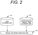
- FIG. 2 is a diagram illustrating functional blocks of a travel pattern creation device 105 that creates a travel pattern.
- the travel pattern creating unit is a risk storage unit 201 in which a risk of the route on which the track transportation system travels is stored, an inter-station travel time storage unit 202 in which the travel time for each inter-station defined on a schedule is stored, and a travel pattern creation unit 203 which creates a travel pattern such that minimizes the risk of the travel pattern while satisfying the inter-running time.
- FIG. 3 illustrates a data format
- a route 301 on which the track transportation system travels is divided into arbitrary sections 302, and the risk evaluation result for each arbitrary section 302 is stored as a table.
- the way of dividing an arbitrary section is, for example, every 100 m. Even if a railroad crossing or a bridge is less than 100 m, it is better to use another section only for this section.
- a section distance may be set longer in a section where an assumed risk is low such as a straight line or an overhead, and a section distance may be set short in a section where an assumed risk is high such as a curve.
- Examples of the risk evaluation result table for each arbitrary section 302 are indicated with 303 and 304.
- Reference numeral 303 denotes a risk evaluation result table for a section where a railroad crossing exists
- reference numeral 304 denotes a risk evaluation result table for a straight section.
- a start mileage and an end mileage indicating which section of the route the risk evaluation result table is for are described.
- a basic risk defined according to the characteristics of the section is described. For example, a high value is set for the basic risk in a section having a high risk of collision with other traffic such as a railroad crossing, and a low basic risk is set for a straight line with good visibility.
- the characteristics of sections include platforms, tunnels, bridges, overhead, underground, curves, slopes, turnouts, steep slopes near tracks, high-rise buildings near tracks, bridges on tracks, etc.
- the risk evaluation result table also describes the speed and the risk at that speed. Generally, as the speed increases, the distance required for braking increases, and the risk of collision increases. Therefore, as the speed increases, a speed-dependent risk is set to a higher value.
- the basic risk and the speed-dependent risk in the risk evaluation result table are determined by estimating the collision probability for each section based on the past case database.
- the speed-dependent risk may be determined based on the degree of damage to the track transportation system at the time of collision using a physical simulation, and may be determined based on the degree of damage.
- the basic risk includes those other than collision risks. For example, the risk of getting on the earth and sand that has flowed into the track, the risk of being blown by the bridge, and the like may be considered.
- An appropriate risk can be grasped according to the actual situation by defining the risk value from the basic risk, which is the first risk value defined according to the characteristics of the section, and the speed-dependent risk, which is a second risk value defined according to the speed.
- FIG. 4 is a flowchart illustrating a processing procedure executed by a travel pattern generation unit 203.
- Steps 401 to 406 a travel pattern is generated.
- the operation based on the flowchart of FIG. 4 is as follows.
- Step 401
- a risk evaluation result table between stations for which a travel pattern is to be created is obtained from the risk storage unit 201. The process proceeds to Step 402.
- the inter-station travel time for which the travel pattern is to be created is acquired from the inter-station travel time storage unit 202, and is set as a reference inter-station travel time. The process proceeds to Step 403.
- a travel pattern that runs at the fastest speed between stations for which a travel pattern is to be created is generated as the fastest travel pattern.
- the process proceeds to Step 404.
- Step 404
- Step 404 Travel pattern candidates 502 and 503 in which the speed is reduced by a predetermined value for each section with respect to the travel pattern 501 to be corrected are created.
- the travel pattern to be corrected is the fastest travel pattern.
- the inter-station travel time and the risk for each of the travel pattern candidates 502 and 503 are calculated.
- the inter-station travel time can be calculated at the same time as creating travel pattern candidates.
- the risk refers to the risk evaluation result table for each section with respect to the travel pattern candidate, and reads out the speed-dependent risk according to the basic risk of the target section and the speed of the travel pattern candidate in the target section.
- the speed at which the speed-dependent risk is read may be an average speed of the travel pattern candidates in the target section or a maximum speed.
- the risks read for each section are summed up to be the risk between stations.
- the difference between the travel time of the travel pattern 501 to be corrected and the inter-station travel time of the travel pattern candidates 502 and 503 is defined as an increased travel time ⁇ t.
- the risk between stations of the travel pattern 501 to be corrected and the risk between stations of the travel pattern candidates 502 and 503 are calculated, and the difference between the risks is defined as a reduced risk ⁇ r. When the risk is reduced, the reduced risk ⁇ r takes a positive value.
- the evaluation function S is calculated for each section.
- ⁇ t 1 of the travel pattern candidate 502 in which the section 1 is changed is 10
- Such a calculation is performed in all sections to evaluate the evaluation function.
- the travel pattern candidate in the section where the evaluation function S is maximized is adopted as the corrected travel pattern 504.
- the travel pattern candidate 503 of the section n is set as the corrected travel pattern 504. The process proceeds to Step 405.
- the inter-station travel time of the corrected travel pattern and the travel time between reference stations are compared. If the inter-station travel time in the corrected travel pattern matches the reference travel time, the process proceeds to Step 406. When the inter-station travel time in the corrected travel pattern is longer or shorter than the reference travel time, the process proceeds to Step 404.
- the condition for proceeding to Step 406 may not be a perfect match. For example, a match may be determined if the travel time between the reference stations is within ⁇ 15 seconds. In this embodiment, it is determined whether the travel times match, but it is also possible to determine whether the distance is within the reference inter-station travel time, such as within ⁇ 10 minutes.
- the travel pattern created in Step 404 is transmitted to the ATO device as a target travel pattern.
- Step 404 a travel pattern that minimizes the risk while satisfying the inter-station travel time using a hill-climbing method has been generated.
- the process in Step 404 is concluded to an optimization problem in which the inter-station travel time is a constraint and the risk is set to the evaluation function. Therefore, the process of Step 404 can be realized even using another optimization method, and for example, a dynamic programming method may be used.
- any method may be employed as long as it is possible to generate a travel pattern with a minimum risk while satisfying the constraint conditions for traveling between stations.
- a travel pattern is created based on a risk value for each section into which a plurality of stations are divided, and it is determined whether the created travel pattern fits within a desired travel time. Therefore, it is possible to create a travel pattern so that the risk of collision between the track transportation system and obstacles is reduced while satisfying the inter-station travel time.
- the value of the risk evaluation table is described as being static in the first embodiment, it may be changed dynamically. For example, in a case where it is detected that the track transportation system is temporarily stopped and the platform is congested as a result of the analysis of a passenger flow, the basic risk near the station platform in the risk evaluation table may be rewritten to a higher value. In addition, the case of a collision accident may be reflected in real time.
- a risk evaluation table for each time may be set. For example, the basic risk of a railroad crossing is increased during the commuting time, and the basic risk of a straight line is set high at night. With this configuration, the risk can be evaluated in more detail. In addition, factors that may change the risk, such as day of the week and weather, may be considered.
- the risk evaluation table may be held for each condition such as time zone and weather, and the risk evaluation table of the condition closest to the current condition may be read.
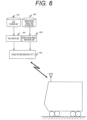
- FIG. 6 is a diagram illustrating a configuration of a travel pattern creation device according to the second embodiment.
- the travel pattern creation unit 605 provided on the ground dynamically creates a travel pattern from the latest risk evaluation information from a risk update unit 603 and the latest inter-station travel time information from an inter-station travel time update unit 604.
- the train is driven according to the travel pattern received by wireless communication.
- Steps 701 to 706 the travel pattern is generated.
- the operation based on the flowchart in FIG. 7 is as follows.
- the latest risk evaluation information between stations whose travel patterns are to be created is acquired from the risk update unit 603. The process proceeds to Step 702.
- the latest travel time between stations for which travel patterns are to be created is acquired from the inter-station travel time update unit 604, and is used as the reference inter-station travel time. The process proceeds to Step 703.
- a travel pattern that runs at the fastest speed between stations for which a travel pattern is to be created is generated as the fastest travel pattern. The process proceeds to Step 704.
- Steps 704 and thereafter are the same as in the first embodiment.
- a recovery travel time may be set in advance, and may be set so as to be automatically input to the inter-station travel time update unit 604 when a delay occurs.
- the risk may be changed according to the weather.
- the risk of an on-bridge section may be set in advance according to the wind speed, and the risk update unit 603 may input the latest risk information from the wind condition information input in real time to the travel pattern creation unit 605.
- Step 707 it may be determined in Step 707 that a travel pattern that fits within the reference travel time cannot be created within a preset risk tolerance value, and a travel time correction signal may be issued in Step 708.
- the determination that the creation is not possible may be made based on whether the determination in Step 705 has been performed a predetermined number of times (for example, 10 times). With such a second determination unit, when the set reference travel time is inappropriate, it can be detected early.
- the correction signal is displayed on a display, a commander can be prompted to input a new travel time to the inter-station travel time update unit 604.
- the signal may be transmitted to the inter-station travel time update unit 604, and the inter-station travel time update unit 604 itself may set a new travel time and transmit the signal to the travel pattern creation unit 605.
- the travel pattern creation device of each embodiment described above it is possible to provide a travel pattern between stations that has suppressed the risk while suppressing the influence on the inter-station travel time by creating the risk on each section where the stations are divided into a plurality of sections and the travel pattern created from the information on the inter-station travel time.
- a determination unit that determines whether the travel pattern created from the information on the risk value is within the reference travel time.
- the risk value is calculated as an evaluation function, so that the travel pattern is created to minimize the risk impact calculated based on the risk value. If the created travel pattern does not fit within the reference travel time, a travel pattern is created again such that the risk impact is minimized within conditions that fit within the reference travel time, and the fitted travel pattern is transmitted as the target travel pattern.
- the travel pattern creation unit 605 of the second embodiment receives the updated risk value transmitted from the risk update unit 603 and the updated inter-station travel time transmitted from the inter-station travel time update unit 604, and dynamically creates the travel pattern.
- the risk update information By dynamically referring to the risk update information, it is possible to realize low-risk traveling according to the abnormal situation at that time.
- the travel time update information By dynamically referring to the travel time update information, it is possible to contribute to the earlier recovery of the delay.
- an automatic train operation device which includes the travel pattern created from information on the risk value and the travel time between stations divided into a plurality of sections, the planning unit 111 for planning a target speed from the speed and the position, the speed deviation calculation unit 113 for calculating a speed deviation from the speed and the target speed, and the tracking unit 112 which receives the speed deviation and outputs a propulsion force, it is possible to provide an automatic operation in which the influence on the inter-station travel time is suppressed and the risk is also suppressed.
- the invention is also applicable to a manned track transportation system.
- a driver is assisted so as to follow the travel pattern created by the travel pattern creation unit.
- the travel pattern may be displayed on a display installed in the driver's cab, or the travel pattern may be converted into a driving operation and then displayed on the display of the driver's cab.
- the travel pattern with the minimum risk has been generated by using the optimization method.
- a travel pattern that minimizes only the risk in the section may be created.
- Each device and each unit described in each embodiment may be provided as an on-board device or a part of the functions thereof, or may be provided as a ground unit such as a command unit or a part of the functions. A similar effect can be obtained in any case as long as the function described in each embodiment is provided.
Landscapes
- Engineering & Computer Science (AREA)
- Mechanical Engineering (AREA)
- Power Engineering (AREA)
- Transportation (AREA)
- Life Sciences & Earth Sciences (AREA)
- Sustainable Development (AREA)
- Sustainable Energy (AREA)
- Train Traffic Observation, Control, And Security (AREA)
- Electric Propulsion And Braking For Vehicles (AREA)
Claims (13)
- Fahrtmustererstellungsvorrichtung (105) zum Erstellen eines Fahrtmusters eines Fahrzeugs, das auf einer Gleisstrecke fährt, umfassend:eine Risikospeichereinheit (201), die ausgelegt ist, um einen Risikowert jedes Abschnitts zu speichern, in die eine Route zwischen Stationen unterteilt ist;eine Speichereinheit (202) für die Fahrzeit zwischen Stationen, die ausgelegt ist, um eine Referenzfahrzeit zwischen Stationen zu speichern, die eine Fahrzeit zwischen jeder Station ist, die in einem Plan für das Fahrzeug definiert ist; undeine Fahrtmustererstellungseinheit (203), die ausgelegt ist, um ein Fahrtmuster als ein Zielfahrtmuster auszugeben, wobei das Zielfahrtmuster eine vorbestimmte Bedingung gemäß der Referenzfahrzeit zwischen Stationen erfüllt und derart ausgelegt ist, dass eine Risikoauswirkung, die basierend auf dem Risikowert jedes Abschnitts berechnet wurde, minimiert wird.
- Fahrtmustererstellungsvorrichtung (105) nach Anspruch 1, wobei die Fahrtmustererstellungseinheit (203) ausgelegt ist, um einen aktualisierten Risikowert zu empfangen, der von einer Risikoaktualisierungseinheit (603) übertragen wurde.
- Fahrtmustererstellungsvorrichtung (105) nach Anspruch 2, wobei der aktualisierte Risikowert aus einer Risikotabelle ausgewählt ist, wobei der aktualisierte Risikowert innerhalb der Risikotabelle im Vorhinein für ein Szenario, in dem der Risikowert geändert wird, eingestellt ist.
- Fahrtmustererstellungsvorrichtung (105) nach Anspruch 3, wobei das Szenario zumindest eines aus einer natürlichen Umgebungsbedingung und einem Passagierstrom umfasst.
- Fahrtmustererstellungsvorrichtung (105) nach Anspruch 1, wobei die Fahrtmustererstellungseinheit (203) ausgelegt ist, um eine aktualisierte Fahrzeit zwischen Stationen zu empfangen, die von einer Aktualisierungseinheit (604) einer Fahrzeit zwischen Stationen übertragen wurde.
- Fahrtmustererstellungsvorrichtung (105) nach einem der vorangegangenen Ansprüche, wobei der Risikowert basierend auf einem Kollisionsrisiko zwischen dem Fahrzeug und von Hindernissen definiert ist.
- Fahrtmustererstellungsvorrichtung (105) nach Anspruch 1, wobei der Risikowert ausgehend von einem ersten Risikowert, der gemäß einem Merkmal des Abschnitts definiert ist, und einem zweiten Risikowert, der gemäß einer Geschwindigkeit des Fahrzeugs definiert ist, berechnet wird.
- Fahrtmustererstellungsvorrichtung (105) nach Anspruch 1, wobei der Risikowert für jeden Abschnitt gemäß einem Vorhandensein oder Nicht-Vorhandensein von zumindest einem eines Bahnübergangs, eines Bahnsteigs, eines Tunnels, einer Brücke, einer Überführung, einer Unterführung, einer Kurve, eines Gefälles, einer Weiche, eines steilen Anstiegs nahe der Gleise, eines Hochhauses nahe der Gleise und einer Struktur auf den Gleisen definiert ist.
- Fahrtmustererstellungsvorrichtung (105) nach Anspruch 1, die ferner Folgendes umfasst:eine erste Bestimmungseinheit, die ausgelegt ist, um zu bestimmen, ob ein Fahrtmuster die vorbestimmte Bedingung gemäß der Fahrzeit zwischen Stationen erfüllt; undeine zweite Bestimmungseinheit, die ausgelegt ist, um zu bestimmen, ob ein Fahrtmuster, das innerhalb eines voreingestellten Risikotoleranzwerts eingepasst ist, in einem Fall erstellt werden kann, in dem die erste Bestimmungseinheit bestimmt, dass das Fahrtmuster nicht akzeptabel ist.
- Automatische Zugbetriebsvorrichtung (101), umfassend:eine Geschwindigkeitsdetektionseinheit (106), die ausgelegt ist, um eine Geschwindigkeit eines Zugs zu detektieren;eine Positionsdetektionseinheit (106), die ausgelegt ist, um eine Position des Zugs zu detektieren;eine Planungseinheit (111), die ausgelegt ist, um eine Zielgeschwindigkeit des Zugs aus einem Fahrtmuster zu planen, das, mit einem Risikowert jedes Abschnitts, in die eine Route zwischen Stationen unterteilt ist, und einer Referenzfahrzeit zwischen Stationen, die eine Fahrzeit zwischen jeder Station ist, die auf einem Plan für den Zug definiert ist, eine vorbestimmte Bedingung gemäß der Referenzfahrzeit zwischen Stationen erfüllt und derartig ist, dass eine Risikoauswirkung, die basierend auf dem Risikowert jedes Abschnitts, der Geschwindigkeit und der Position berechnet wird, minimiert wird;eine Geschwindigkeitsabweichungsberechnungseinheit (113), die ausgelegt ist, um eine Geschwindigkeitsabweichung von der Geschwindigkeit und der Zielgeschwindigkeit zu berechnen; undeine Nachverfolgungseinheit (112), die ausgelegt ist, um die Geschwindigkeitsabweichung zu empfangen, eine Antriebskraft des Zugs zu berechnen und einen Antriebsbefehl, einschließlich der Antriebskraft, an ein Zugsteuerungs- und - verwaltungssystem (102) oder eine Antriebssteuervorrichtung (103) auszugeben.
- Automatische Zugbetriebsvorrichtung (101) nach Anspruch 10, wobei der Risikowert basierend auf einem Risiko einer Kollision zwischen dem Zug und von Hindernissen definiert wird.
- Fahrtmustererstellungsverfahren zum Erstellen eines Fahrtmusters eines Fahrzeugs, das auf einem Gleis fährt, wobei das Verfahren folgende Schritte umfasst:Erstellen eines Fahrtmusters, das eine Risikoauswirkung minimiert, die ausgehend von einem Risikowert jedes Abschnitts berechnet wurde, in die eine Route zwischen Stationen unterteilt ist;Bestimmen, ob das erstellte Fahrtmuster eine vorbestimmte Bedingung gemäß einer Referenzfahrzeit zwischen Stationen erfüllt, wobei die Referenzfahrzeit zwischen Stationen eine Fahrzeit zwischen jeder Station ist, die in einem Plan für das Fahrzeug definiert ist; undAusgeben des bestimmten Fahrtmusters, um die vorbestimmte Bedingung als ein Zielfahrtmuster zu erfüllen.
- Fahrtmustererstellungsverfahren nach Anspruch 12, wobei der Risikowert basierend auf einem Risiko einer Kollision zwischen dem Fahrzeug und von Hindernissen definiert ist.
Applications Claiming Priority (2)
| Application Number | Priority Date | Filing Date | Title |
|---|---|---|---|
| JP2018013167A JP7164306B2 (ja) | 2018-01-30 | 2018-01-30 | 走行パターン作成装置、走行パターン作成方法および自動列車運転装置 |
| PCT/JP2019/000826 WO2019150925A1 (ja) | 2018-01-30 | 2019-01-15 | 走行パターン作成装置、走行パターン作成方法および自動列車運転装置 |
Publications (3)
| Publication Number | Publication Date |
|---|---|
| EP3747686A1 EP3747686A1 (de) | 2020-12-09 |
| EP3747686A4 EP3747686A4 (de) | 2021-11-10 |
| EP3747686B1 true EP3747686B1 (de) | 2025-05-14 |
Family
ID=67478690
Family Applications (1)
| Application Number | Title | Priority Date | Filing Date |
|---|---|---|---|
| EP19746865.5A Active EP3747686B1 (de) | 2018-01-30 | 2019-01-15 | Vorrichtung, zur erzeugung von fahrmustern, verfahren zur erzeugung von fahrmustern und vorrichtung für automatischen zugbetrieb |
Country Status (3)
| Country | Link |
|---|---|
| EP (1) | EP3747686B1 (de) |
| JP (1) | JP7164306B2 (de) |
| WO (1) | WO2019150925A1 (de) |
Families Citing this family (3)
| Publication number | Priority date | Publication date | Assignee | Title |
|---|---|---|---|---|
| JP7488061B2 (ja) * | 2020-02-27 | 2024-05-21 | 株式会社日立製作所 | 走行パタン作成装置及びそれを用いた運転制御方法 |
| CN112158237B (zh) * | 2020-09-24 | 2022-07-19 | 交控科技股份有限公司 | 集成tcms和ato功能的深度融合系统和列车 |
| JP7466507B2 (ja) * | 2021-09-03 | 2024-04-12 | 株式会社日立製作所 | 走行パターン作成装置および走行パターン作成方法 |
Citations (1)
| Publication number | Priority date | Publication date | Assignee | Title |
|---|---|---|---|---|
| EP2923913B1 (de) * | 2014-03-25 | 2018-11-21 | Hitachi Ltd. | Automatisiertes Zugbetriebssystem |
Family Cites Families (6)
| Publication number | Priority date | Publication date | Assignee | Title |
|---|---|---|---|---|
| JPH07285439A (ja) * | 1994-04-19 | 1995-10-31 | Hitachi Ltd | 遺伝的アルゴリズム/ニューロによる列車ダイヤ作成装置及び作成方法 |
| JP3431430B2 (ja) * | 1996-12-12 | 2003-07-28 | 株式会社日立製作所 | 列車情報伝送方法、列車速度制御方法および列車制御システム |
| JP3881302B2 (ja) | 2002-11-06 | 2007-02-14 | 財団法人鉄道総合技術研究所 | 運転曲線作成装置及び運転曲線作成情報 |
| JP6334282B2 (ja) * | 2014-06-11 | 2018-05-30 | 株式会社東芝 | 情報処理装置および運転曲線作成方法 |
| JP6357359B2 (ja) * | 2014-06-13 | 2018-07-11 | 公益財団法人鉄道総合技術研究所 | 衝突被害軽減方法および衝突被害軽減システム |
| JP6736392B2 (ja) * | 2016-07-07 | 2020-08-05 | 株式会社日立製作所 | 走行パターン作成装置及び走行パターン作成方法 |
-
2018
- 2018-01-30 JP JP2018013167A patent/JP7164306B2/ja active Active
-
2019
- 2019-01-15 WO PCT/JP2019/000826 patent/WO2019150925A1/ja not_active Ceased
- 2019-01-15 EP EP19746865.5A patent/EP3747686B1/de active Active
Patent Citations (1)
| Publication number | Priority date | Publication date | Assignee | Title |
|---|---|---|---|---|
| EP2923913B1 (de) * | 2014-03-25 | 2018-11-21 | Hitachi Ltd. | Automatisiertes Zugbetriebssystem |
Also Published As
| Publication number | Publication date |
|---|---|
| JP2019134532A (ja) | 2019-08-08 |
| EP3747686A1 (de) | 2020-12-09 |
| JP7164306B2 (ja) | 2022-11-01 |
| EP3747686A4 (de) | 2021-11-10 |
| WO2019150925A1 (ja) | 2019-08-08 |
Similar Documents
| Publication | Publication Date | Title |
|---|---|---|
| AU2016225956B2 (en) | System and method for controlling a vehicle system to achieve different objectives during a trip | |
| US9150229B2 (en) | Systems and method for controlling warnings at vehicle crossings | |
| US8370006B2 (en) | Method and apparatus for optimizing a train trip using signal information | |
| US8645047B2 (en) | System and method for optimizing vehicle performance in presence of changing optimization parameters | |
| AU2014100528A4 (en) | Systems and methods for determining route location | |
| AU2019213446B2 (en) | Method and apparatus for learning and validating brake deceleration rates | |
| US12195059B2 (en) | Vehicle control system | |
| JP5171712B2 (ja) | 踏切制御装置 | |
| US20100174440A1 (en) | Driving Assistance Method and Device for a Vehicle for Travelling Along a Predetermined Path Between a First Point and a Second Point | |
| US10279823B2 (en) | System for controlling or monitoring a vehicle system along a route | |
| US20090184214A1 (en) | System and Method for Train Operation Approaching Grade Crossings | |
| CN104379396A (zh) | 列车控制装置 | |
| AU2021203760B2 (en) | Energy management system and method for vehicle systems | |
| WO2020021282A1 (en) | Determining position of a vehicle on a rail | |
| AU2017201725A1 (en) | Train driving assistant system | |
| EP3747686B1 (de) | Vorrichtung, zur erzeugung von fahrmustern, verfahren zur erzeugung von fahrmustern und vorrichtung für automatischen zugbetrieb | |
| US11993299B2 (en) | Vehicle brake control system and method | |
| CN112706802B (zh) | 一种磁浮列车安全防护的方法及装置 | |
| JP2008184076A (ja) | 列車運行管理システム | |
| JP2021035069A (ja) | 鉄道車両の自動運転装置および列車自動運転システム | |
| KR102860197B1 (ko) | 노면 전차의 운행 제어 방법 및 이를 위한 안전 운행 제어 장치 | |
| JP7291284B1 (ja) | 車上装置 | |
| JP2025039176A (ja) | 走行パターン生成装置、車両及び走行パターン生成方法 | |
| CN120428730A (zh) | 用于干线物流的货运卡车协同编队运输系统 | |
| KR101481800B1 (ko) | 트램간 안전거리유지장치 및 트램간 안전거리유지장치의 동작 방법 |
Legal Events
| Date | Code | Title | Description |
|---|---|---|---|
| STAA | Information on the status of an ep patent application or granted ep patent |
Free format text: STATUS: THE INTERNATIONAL PUBLICATION HAS BEEN MADE |
|
| PUAI | Public reference made under article 153(3) epc to a published international application that has entered the european phase |
Free format text: ORIGINAL CODE: 0009012 |
|
| STAA | Information on the status of an ep patent application or granted ep patent |
Free format text: STATUS: REQUEST FOR EXAMINATION WAS MADE |
|
| 17P | Request for examination filed |
Effective date: 20200430 |
|
| AK | Designated contracting states |
Kind code of ref document: A1 Designated state(s): AL AT BE BG CH CY CZ DE DK EE ES FI FR GB GR HR HU IE IS IT LI LT LU LV MC MK MT NL NO PL PT RO RS SE SI SK SM TR |
|
| AX | Request for extension of the european patent |
Extension state: BA ME |
|
| DAV | Request for validation of the european patent (deleted) | ||
| DAX | Request for extension of the european patent (deleted) | ||
| A4 | Supplementary search report drawn up and despatched |
Effective date: 20211007 |
|
| RIC1 | Information provided on ipc code assigned before grant |
Ipc: B60L 15/20 20060101ALI20211002BHEP Ipc: B60L 3/00 20190101ALI20211002BHEP Ipc: B61L 27/00 20060101ALI20211002BHEP Ipc: B60L 15/40 20060101AFI20211002BHEP |
|
| REG | Reference to a national code |
Ref legal event code: R079 Ipc: B61L0015000000 Ref country code: DE Ref legal event code: R079 Ref document number: 602019069966 Country of ref document: DE Free format text: PREVIOUS MAIN CLASS: B60L0015400000 Ipc: B61L0015000000 |
|
| GRAP | Despatch of communication of intention to grant a patent |
Free format text: ORIGINAL CODE: EPIDOSNIGR1 |
|
| STAA | Information on the status of an ep patent application or granted ep patent |
Free format text: STATUS: GRANT OF PATENT IS INTENDED |
|
| RIC1 | Information provided on ipc code assigned before grant |
Ipc: B60L 15/40 20060101ALI20250103BHEP Ipc: B60L 15/04 20060101ALI20250103BHEP Ipc: B60L 15/20 20060101ALI20250103BHEP Ipc: B60L 3/00 20190101ALI20250103BHEP Ipc: B61L 27/20 20220101ALI20250103BHEP Ipc: B61L 27/16 20220101ALI20250103BHEP Ipc: B61L 27/04 20060101ALI20250103BHEP Ipc: B61L 15/00 20060101AFI20250103BHEP |
|
| INTG | Intention to grant announced |
Effective date: 20250210 |
|
| GRAS | Grant fee paid |
Free format text: ORIGINAL CODE: EPIDOSNIGR3 |
|
| GRAA | (expected) grant |
Free format text: ORIGINAL CODE: 0009210 |
|
| STAA | Information on the status of an ep patent application or granted ep patent |
Free format text: STATUS: THE PATENT HAS BEEN GRANTED |
|
| AK | Designated contracting states |
Kind code of ref document: B1 Designated state(s): AL AT BE BG CH CY CZ DE DK EE ES FI FR GB GR HR HU IE IS IT LI LT LU LV MC MK MT NL NO PL PT RO RS SE SI SK SM TR |
|
| REG | Reference to a national code |
Ref country code: GB Ref legal event code: FG4D |
|
| REG | Reference to a national code |
Ref country code: CH Ref legal event code: EP |
|
| REG | Reference to a national code |
Ref country code: IE Ref legal event code: FG4D |
|
| REG | Reference to a national code |
Ref country code: DE Ref legal event code: R096 Ref document number: 602019069966 Country of ref document: DE |
|
| REG | Reference to a national code |
Ref country code: NL Ref legal event code: MP Effective date: 20250514 |
|
| PG25 | Lapsed in a contracting state [announced via postgrant information from national office to epo] |
Ref country code: PT Free format text: LAPSE BECAUSE OF FAILURE TO SUBMIT A TRANSLATION OF THE DESCRIPTION OR TO PAY THE FEE WITHIN THE PRESCRIBED TIME-LIMIT Effective date: 20250915 Ref country code: ES Free format text: LAPSE BECAUSE OF FAILURE TO SUBMIT A TRANSLATION OF THE DESCRIPTION OR TO PAY THE FEE WITHIN THE PRESCRIBED TIME-LIMIT Effective date: 20250514 Ref country code: FI Free format text: LAPSE BECAUSE OF FAILURE TO SUBMIT A TRANSLATION OF THE DESCRIPTION OR TO PAY THE FEE WITHIN THE PRESCRIBED TIME-LIMIT Effective date: 20250514 |
|
| REG | Reference to a national code |
Ref country code: LT Ref legal event code: MG9D |
|
| PG25 | Lapsed in a contracting state [announced via postgrant information from national office to epo] |
Ref country code: GR Free format text: LAPSE BECAUSE OF FAILURE TO SUBMIT A TRANSLATION OF THE DESCRIPTION OR TO PAY THE FEE WITHIN THE PRESCRIBED TIME-LIMIT Effective date: 20250815 Ref country code: NO Free format text: LAPSE BECAUSE OF FAILURE TO SUBMIT A TRANSLATION OF THE DESCRIPTION OR TO PAY THE FEE WITHIN THE PRESCRIBED TIME-LIMIT Effective date: 20250814 |
|
| PG25 | Lapsed in a contracting state [announced via postgrant information from national office to epo] |
Ref country code: PL Free format text: LAPSE BECAUSE OF FAILURE TO SUBMIT A TRANSLATION OF THE DESCRIPTION OR TO PAY THE FEE WITHIN THE PRESCRIBED TIME-LIMIT Effective date: 20250514 Ref country code: NL Free format text: LAPSE BECAUSE OF FAILURE TO SUBMIT A TRANSLATION OF THE DESCRIPTION OR TO PAY THE FEE WITHIN THE PRESCRIBED TIME-LIMIT Effective date: 20250514 |
|
| REG | Reference to a national code |
Ref country code: AT Ref legal event code: MK05 Ref document number: 1794574 Country of ref document: AT Kind code of ref document: T Effective date: 20250514 |
|
| PG25 | Lapsed in a contracting state [announced via postgrant information from national office to epo] |
Ref country code: BG Free format text: LAPSE BECAUSE OF FAILURE TO SUBMIT A TRANSLATION OF THE DESCRIPTION OR TO PAY THE FEE WITHIN THE PRESCRIBED TIME-LIMIT Effective date: 20250514 |
|
| PG25 | Lapsed in a contracting state [announced via postgrant information from national office to epo] |
Ref country code: HR Free format text: LAPSE BECAUSE OF FAILURE TO SUBMIT A TRANSLATION OF THE DESCRIPTION OR TO PAY THE FEE WITHIN THE PRESCRIBED TIME-LIMIT Effective date: 20250514 |
|
| PG25 | Lapsed in a contracting state [announced via postgrant information from national office to epo] |
Ref country code: AT Free format text: LAPSE BECAUSE OF FAILURE TO SUBMIT A TRANSLATION OF THE DESCRIPTION OR TO PAY THE FEE WITHIN THE PRESCRIBED TIME-LIMIT Effective date: 20250514 |
|
| PG25 | Lapsed in a contracting state [announced via postgrant information from national office to epo] |
Ref country code: RS Free format text: LAPSE BECAUSE OF FAILURE TO SUBMIT A TRANSLATION OF THE DESCRIPTION OR TO PAY THE FEE WITHIN THE PRESCRIBED TIME-LIMIT Effective date: 20250814 |
|
| PG25 | Lapsed in a contracting state [announced via postgrant information from national office to epo] |
Ref country code: IS Free format text: LAPSE BECAUSE OF FAILURE TO SUBMIT A TRANSLATION OF THE DESCRIPTION OR TO PAY THE FEE WITHIN THE PRESCRIBED TIME-LIMIT Effective date: 20250914 |
|
| PG25 | Lapsed in a contracting state [announced via postgrant information from national office to epo] |
Ref country code: LV Free format text: LAPSE BECAUSE OF FAILURE TO SUBMIT A TRANSLATION OF THE DESCRIPTION OR TO PAY THE FEE WITHIN THE PRESCRIBED TIME-LIMIT Effective date: 20250514 |
|
| PG25 | Lapsed in a contracting state [announced via postgrant information from national office to epo] |
Ref country code: SM Free format text: LAPSE BECAUSE OF FAILURE TO SUBMIT A TRANSLATION OF THE DESCRIPTION OR TO PAY THE FEE WITHIN THE PRESCRIBED TIME-LIMIT Effective date: 20250514 Ref country code: DK Free format text: LAPSE BECAUSE OF FAILURE TO SUBMIT A TRANSLATION OF THE DESCRIPTION OR TO PAY THE FEE WITHIN THE PRESCRIBED TIME-LIMIT Effective date: 20250514 |
|
| PG25 | Lapsed in a contracting state [announced via postgrant information from national office to epo] |
Ref country code: CZ Free format text: LAPSE BECAUSE OF FAILURE TO SUBMIT A TRANSLATION OF THE DESCRIPTION OR TO PAY THE FEE WITHIN THE PRESCRIBED TIME-LIMIT Effective date: 20250514 |
|
| PG25 | Lapsed in a contracting state [announced via postgrant information from national office to epo] |
Ref country code: EE Free format text: LAPSE BECAUSE OF FAILURE TO SUBMIT A TRANSLATION OF THE DESCRIPTION OR TO PAY THE FEE WITHIN THE PRESCRIBED TIME-LIMIT Effective date: 20250514 |
|
| PG25 | Lapsed in a contracting state [announced via postgrant information from national office to epo] |
Ref country code: RO Free format text: LAPSE BECAUSE OF FAILURE TO SUBMIT A TRANSLATION OF THE DESCRIPTION OR TO PAY THE FEE WITHIN THE PRESCRIBED TIME-LIMIT Effective date: 20250514 Ref country code: SK Free format text: LAPSE BECAUSE OF FAILURE TO SUBMIT A TRANSLATION OF THE DESCRIPTION OR TO PAY THE FEE WITHIN THE PRESCRIBED TIME-LIMIT Effective date: 20250514 |
|
| REG | Reference to a national code |
Ref country code: DE Ref legal event code: R097 Ref document number: 602019069966 Country of ref document: DE |
|
| PLBE | No opposition filed within time limit |
Free format text: ORIGINAL CODE: 0009261 |
|
| STAA | Information on the status of an ep patent application or granted ep patent |
Free format text: STATUS: NO OPPOSITION FILED WITHIN TIME LIMIT |
|
| REG | Reference to a national code |
Ref country code: CH Ref legal event code: L10 Free format text: ST27 STATUS EVENT CODE: U-0-0-L10-L00 (AS PROVIDED BY THE NATIONAL OFFICE) Effective date: 20260325 |
|
| PGFP | Annual fee paid to national office [announced via postgrant information from national office to epo] |
Ref country code: GB Payment date: 20260119 Year of fee payment: 8 |
|
| PGFP | Annual fee paid to national office [announced via postgrant information from national office to epo] |
Ref country code: DE Payment date: 20260122 Year of fee payment: 8 |
|
| PGFP | Annual fee paid to national office [announced via postgrant information from national office to epo] |
Ref country code: IT Payment date: 20251124 Year of fee payment: 8 |
|
| PGFP | Annual fee paid to national office [announced via postgrant information from national office to epo] |
Ref country code: FR Payment date: 20260122 Year of fee payment: 8 |
|
| 26N | No opposition filed |
Effective date: 20260217 |