EP3747225B1 - Procédé et appareil pour déclencher une sélection de porteuse de transmission dans un système de communications sans fil - Google Patents
Procédé et appareil pour déclencher une sélection de porteuse de transmission dans un système de communications sans fil Download PDFInfo
- Publication number
- EP3747225B1 EP3747225B1 EP19800811.2A EP19800811A EP3747225B1 EP 3747225 B1 EP3747225 B1 EP 3747225B1 EP 19800811 A EP19800811 A EP 19800811A EP 3747225 B1 EP3747225 B1 EP 3747225B1
- Authority
- EP
- European Patent Office
- Prior art keywords
- carrier
- sidelink
- cbr
- transmission
- stch
- Prior art date
- Legal status (The legal status is an assumption and is not a legal conclusion. Google has not performed a legal analysis and makes no representation as to the accuracy of the status listed.)
- Active
Links
- 230000005540 biological transmission Effects 0.000 title claims description 203
- 238000004891 communication Methods 0.000 title claims description 122
- 238000000034 method Methods 0.000 title claims description 72
- 239000000969 carrier Substances 0.000 claims description 66
- 238000005259 measurement Methods 0.000 claims description 41
- 238000010187 selection method Methods 0.000 claims description 15
- 102100032489 Heat shock 70 kDa protein 13 Human genes 0.000 claims 12
- 101001016638 Homo sapiens Heat shock 70 kDa protein 13 Proteins 0.000 claims 12
- 101000720079 Stichodactyla helianthus DELTA-stichotoxin-She4a Proteins 0.000 claims 12
- 230000006870 function Effects 0.000 description 47
- 230000001960 triggered effect Effects 0.000 description 31
- 230000008569 process Effects 0.000 description 29
- 238000007726 management method Methods 0.000 description 17
- 239000000872 buffer Substances 0.000 description 16
- 238000013468 resource allocation Methods 0.000 description 15
- 238000013507 mapping Methods 0.000 description 13
- 238000012546 transfer Methods 0.000 description 13
- 230000000737 periodic effect Effects 0.000 description 12
- 238000012913 prioritisation Methods 0.000 description 8
- 238000005516 engineering process Methods 0.000 description 7
- 238000010586 diagram Methods 0.000 description 5
- 238000012545 processing Methods 0.000 description 5
- 230000006978 adaptation Effects 0.000 description 4
- 230000011218 segmentation Effects 0.000 description 4
- 230000011664 signaling Effects 0.000 description 4
- 238000004873 anchoring Methods 0.000 description 3
- 230000003247 decreasing effect Effects 0.000 description 3
- 230000008520 organization Effects 0.000 description 3
- 230000004913 activation Effects 0.000 description 2
- 238000012937 correction Methods 0.000 description 2
- 230000007774 longterm Effects 0.000 description 2
- 238000012423 maintenance Methods 0.000 description 2
- 238000012544 monitoring process Methods 0.000 description 2
- 230000002776 aggregation Effects 0.000 description 1
- 238000004220 aggregation Methods 0.000 description 1
- 230000001413 cellular effect Effects 0.000 description 1
- 230000008859 change Effects 0.000 description 1
- 230000006835 compression Effects 0.000 description 1
- 238000007906 compression Methods 0.000 description 1
- 238000007796 conventional method Methods 0.000 description 1
- 230000006837 decompression Effects 0.000 description 1
- 230000001419 dependent effect Effects 0.000 description 1
- 238000001514 detection method Methods 0.000 description 1
- 230000000694 effects Effects 0.000 description 1
- 238000001914 filtration Methods 0.000 description 1
- 230000004044 response Effects 0.000 description 1
- 238000001228 spectrum Methods 0.000 description 1
- 230000007704 transition Effects 0.000 description 1
Images


Classifications
-
- H—ELECTRICITY
- H04—ELECTRIC COMMUNICATION TECHNIQUE
- H04W—WIRELESS COMMUNICATION NETWORKS
- H04W72/00—Local resource management
- H04W72/02—Selection of wireless resources by user or terminal
-
- H—ELECTRICITY
- H04—ELECTRIC COMMUNICATION TECHNIQUE
- H04L—TRANSMISSION OF DIGITAL INFORMATION, e.g. TELEGRAPHIC COMMUNICATION
- H04L1/00—Arrangements for detecting or preventing errors in the information received
- H04L1/0001—Systems modifying transmission characteristics according to link quality, e.g. power backoff
- H04L1/0002—Systems modifying transmission characteristics according to link quality, e.g. power backoff by adapting the transmission rate
- H04L1/0003—Systems modifying transmission characteristics according to link quality, e.g. power backoff by adapting the transmission rate by switching between different modulation schemes
-
- H—ELECTRICITY
- H04—ELECTRIC COMMUNICATION TECHNIQUE
- H04W—WIRELESS COMMUNICATION NETWORKS
- H04W36/00—Hand-off or reselection arrangements
- H04W36/03—Reselecting a link using a direct mode connection
- H04W36/037—Reselecting a link using a direct mode connection by reducing handover delay, e.g. latency
-
- H—ELECTRICITY
- H04—ELECTRIC COMMUNICATION TECHNIQUE
- H04W—WIRELESS COMMUNICATION NETWORKS
- H04W36/00—Hand-off or reselection arrangements
- H04W36/08—Reselecting an access point
-
- H—ELECTRICITY
- H04—ELECTRIC COMMUNICATION TECHNIQUE
- H04W—WIRELESS COMMUNICATION NETWORKS
- H04W4/00—Services specially adapted for wireless communication networks; Facilities therefor
- H04W4/30—Services specially adapted for particular environments, situations or purposes
- H04W4/40—Services specially adapted for particular environments, situations or purposes for vehicles, e.g. vehicle-to-pedestrians [V2P]
-
- H—ELECTRICITY
- H04—ELECTRIC COMMUNICATION TECHNIQUE
- H04W—WIRELESS COMMUNICATION NETWORKS
- H04W72/00—Local resource management
- H04W72/04—Wireless resource allocation
- H04W72/044—Wireless resource allocation based on the type of the allocated resource
- H04W72/0453—Resources in frequency domain, e.g. a carrier in FDMA
-
- H—ELECTRICITY
- H04—ELECTRIC COMMUNICATION TECHNIQUE
- H04W—WIRELESS COMMUNICATION NETWORKS
- H04W72/00—Local resource management
- H04W72/20—Control channels or signalling for resource management
- H04W72/23—Control channels or signalling for resource management in the downlink direction of a wireless link, i.e. towards a terminal
-
- H—ELECTRICITY
- H04—ELECTRIC COMMUNICATION TECHNIQUE
- H04W—WIRELESS COMMUNICATION NETWORKS
- H04W74/00—Wireless channel access
- H04W74/08—Non-scheduled access, e.g. ALOHA
- H04W74/0808—Non-scheduled access, e.g. ALOHA using carrier sensing, e.g. carrier sense multiple access [CSMA]
-
- H—ELECTRICITY
- H04—ELECTRIC COMMUNICATION TECHNIQUE
- H04W—WIRELESS COMMUNICATION NETWORKS
- H04W76/00—Connection management
- H04W76/10—Connection setup
- H04W76/14—Direct-mode setup
-
- H—ELECTRICITY
- H04—ELECTRIC COMMUNICATION TECHNIQUE
- H04W—WIRELESS COMMUNICATION NETWORKS
- H04W76/00—Connection management
- H04W76/20—Manipulation of established connections
- H04W76/27—Transitions between radio resource control [RRC] states
-
- H—ELECTRICITY
- H04—ELECTRIC COMMUNICATION TECHNIQUE
- H04W—WIRELESS COMMUNICATION NETWORKS
- H04W92/00—Interfaces specially adapted for wireless communication networks
- H04W92/16—Interfaces between hierarchically similar devices
- H04W92/18—Interfaces between hierarchically similar devices between terminal devices
-
- H—ELECTRICITY
- H04—ELECTRIC COMMUNICATION TECHNIQUE
- H04L—TRANSMISSION OF DIGITAL INFORMATION, e.g. TELEGRAPHIC COMMUNICATION
- H04L5/00—Arrangements affording multiple use of the transmission path
- H04L5/0001—Arrangements for dividing the transmission path
- H04L5/0003—Two-dimensional division
- H04L5/0005—Time-frequency
- H04L5/0007—Time-frequency the frequencies being orthogonal, e.g. OFDM(A), DMT
- H04L5/001—Time-frequency the frequencies being orthogonal, e.g. OFDM(A), DMT the frequencies being arranged in component carriers
-
- H—ELECTRICITY
- H04—ELECTRIC COMMUNICATION TECHNIQUE
- H04W—WIRELESS COMMUNICATION NETWORKS
- H04W80/00—Wireless network protocols or protocol adaptations to wireless operation
- H04W80/02—Data link layer protocols
Definitions
- the present disclosure generally relates to wireless communications.
- Wireless communication systems generally aim to reduce costs for users and providers, improve service quality, and expand and improve coverage and system capacity. To achieve these goals, in some scenarios, wireless communication systems are designed to reduced cost per bit, increased service availability, flexible use of a frequency band, a simple structure, an open interface, and adequate power consumption of a terminal as an upper-level requirement.
- 3rd Generation Partnership Project; Technical Specification Group Radio Access Network; Evolved Universal Terrestrial Radio Access (E-UTRA); Medium Access Control (MAC) Protocol specification (Release 14) 3GPP TS 36.321 V14.5.0 is directed to a UE that uses a sidelink grant if a data is available in STCH. But if the sidelink grant cannot accommodate RLC SDU so that a transmission of the data is not possible using the sidelink grant, the UE performs a sidelink resource reselection.
- WO 2018/062857 A1 discloses a condition for a media access control (MAC) entity in user equipment (UE) reselecting a sidelink resource in a wireless communication system.
- MAC media access control
- EP 3 148 283 A1 describes a method and apparatus for reducing signaling overhead in a wireless communication system.
- the method includes a process of requiring the resource pools configuration from the eNB and then broadcast to the remote UEs that conduct ProSe transmission with resources selected from the pools.
- a conventional method of SL-SCH Data transfer is proposed in " Draft running CR of 36.321 for eV2X", 3GPP TSG-RAN2 Meeting #101bis R2-12806027, 13 April 2018, XP051435783 , Sanya, China.
- themethod includes the operation: if a pool of resources is configured or reconfigured by upper layers: trigger the TX carrier reselection procedure.
- Implementations are disclosed herein that enable triggering a transmission carrier selection in a wireless communication system.
- Transmission carrier selection procedure can be efficiently triggered.
- V2X communication is the communication of information from a vehicle to an entity that may affect the vehicle, and vice versa.
- Examples of V2X include vehicle-to-infrastructure (V2I), vehicle-to-network (V2N), vehicle-to-vehicle (V2V), vehicle-to-pedestrian (V2P), vehicle-to-device (V2D), and vehicle-to-grid (V2G).
- V2I vehicle-to-infrastructure
- V2N vehicle-to-network
- V2V vehicle-to-vehicle
- V2P vehicle-to-pedestrian
- V2D vehicle-to-device
- V2G vehicle-to-grid
- V2X systems may be designed to achieve various objectives, such as road safety, traffic efficiency, and energy savings.
- V2X communication technology may be classified into two types, depending on the underlying technology: wireless local area network (WLAN)-based V2X, and cellular-based V2X.
- WLAN wireless local area network
- V2X sidelink communication may be supported.
- some V2X sidelink communications may support carrier aggregation (CA).
- CA carrier aggregation
- a carrier may be initially selected or may be re-selected among the aggregated carriers.
- There may be various conditions for triggering carrier (re-)selection in such V2X sidelink CA scenarios.
- conditions for triggering sidelink resource selection may be used as conditions for triggering transmission carrier (re-)selection.
- other types of triggering conditions may be implemented for transmission carrier (re-)selection.
- new triggering conditions for TX carrier (re-)selection are implemented.
- a new triggering condition may be implemented such that (i) even if an upper layer configures multiple carriers for a first V2X service and the MAC entity selects a carrier among those multiple configured carriers, and (ii) if new data for a second V2X service is available in a logical channel which is not associated with that currently selected carrier, then the TX carrier (re-) selection is triggered and a new carrier for the second V2X service may be selected.
- the 3rd generation partnership project (3GPP) long-term evolution (LTE) is a technology designed to enable high-speed packet communications.
- 3GPP international telecommunication union
- 3GPP have developed technical standards for new radio (NR) systems.
- technology is being identified and developed to successfully standardize the new radio access technology (RAT), in order to timely satisfy both urgent market needs, as well as longer-term goals and requirements set forth by the ITU radio communication sector (ITU-R) international mobile telecommunications (IMT)-2020 process.
- NR is being designed to use any spectrum band ranging at least up to 100 GHz, which may be made available for wireless communications even in a more distant future.
- the NR targets a technical framework addressing various usage scenarios, requirements, and deployment scenarios, such as, for example, enhanced mobile broadband (eMBB), massive machine-type-communications (mMTC), ultra-reliable and low latency communications (URLLC), etc.
- eMBB enhanced mobile broadband
- mMTC massive machine-type-communications
- URLLC ultra-reliable and low latency communications
- one or more technical features described below may be compatible with one or more technical standards, such as those used by a communication standard by the 3rd generation partnership project (3GPP) standardization organization, a communication standard by the institute of electrical and electronics engineers (IEEE), etc.
- the communication standards by the 3GPP standardization organization include long-term evolution (LTE) and/or evolution of LTE systems.
- LTE long-term evolution
- LTE-A LTE-advanced
- LTE-A Pro LTE-A Pro
- NR 5G new radio
- the communication standard by the IEEE standardization organization includes a wireless local area network (WLAN) system such as IEEE 802.11a/b/g/n/ac/ax.
- WLAN wireless local area network
- the above system uses various multiple access technologies such as orthogonal frequency division multiple access (OFDMA) and/or single carrier frequency division multiple access (SC-FDMA) for downlink (DL) and/or uplink (DL).
- OFDMA orthogonal frequency division multiple access
- SC-FDMA single carrier frequency division multiple access
- OFDMA and SC-FDMA may be used for DL and/or UL.
- the term “/” and “,” should be interpreted to indicate “and/or.”
- the expression “A/B” may mean “A and/or B.”
- A, B may mean “A and/or B.”
- A/B/C may mean “at least one of A, B, and/or C.”
- A, B, C may mean “at least one of A, B, and/or C.”
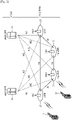
- FIG. 1 shows an example of a wireless communication system to which technical features of the present disclosure can be applied.
- the system of FIG. 1 may be compatible with an evolved-UMTS terrestrial radio access network (E-UTRAN).
- E-UTRAN evolved-UMTS terrestrial radio access network
- LTE may be a part of an evolved-UTMS (e-UMTS) using the E-UTRAN.
- e-UMTS evolved-UTMS
- the wireless communication system includes one or more user equipment (UE; 10), an E-UTRAN and an evolved packet core (EPC).
- the UE 10 may be a communication equipment carried by a user.
- the UE 10 may be fixed or mobile.
- the UE 10 may be referred to by various terminologies, such as a mobile station (MS), a user terminal (UT), a subscriber station (SS), a wireless device, etc.
- the E-UTRAN consists of one or more base stations (BSs), such as BS 20.
- the BS 20 provides the E-UTRA user plane and control plane protocol terminations towards the UE 10.
- the BS 20 may be a fixed station that communicates with the UE 10.
- the BS 20 may host various functions, such as, for example, inter-cell radio resource management (MME), radio bearer (RB) control, connection mobility control, radio admission control, measurement configuration/ provision, dynamic resource allocation (scheduler), etc.
- MME inter-cell radio resource management
- RB radio bearer
- connection mobility control such as connection mobility control
- radio admission control such as measurement configuration/ provision
- the BS may be referred to using various terminologies, such as an evolved NodeB (eNB), a base transceiver system (BTS), an access point (AP), etc.
- eNB evolved NodeB
- BTS base transceiver system
- AP access point
- a downlink (DL) denotes communication from the BS 20 to the UE 10.
- An uplink (UL) denotes communication from the UE 10 to the BS 20.
- a sidelink (SL) denotes communication between the UEs 10.
- a transmitter may be a part of the BS 20, and a receiver may be a part of the UE 10.
- the transmitter may be a part of the UE 10
- the receiver may be a part of the BS 20.
- the transmitter and receiver may be a part of the UE 10.
- the EPC includes a mobility management entity (MME), a serving gateway (S-GW) and a packet data network (PDN) gateway (P-GW).
- MME mobility management entity
- S-GW serving gateway
- PDN packet data network gateway
- the MME hosts various functions, such as, for example, non-access stratum (NAS) security, idle state mobility handling, evolved packet system (EPS) bearer control, etc.
- the S-GW hosts various functions, such as, for example, mobility anchoring, etc.
- the S-GW is a gateway having an E-UTRAN as an endpoint.
- MME/S-GW 30 will be referred to herein simply as a "gateway," but it is understood that this entity includes both the MME and S-GW.
- the P-GW hosts various functions, such as, for example, UE Internet protocol (IP) address allocation, packet filtering, etc.
- IP Internet protocol
- the P-GW is a gateway having a PDN as an endpoint.
- the P-GW is connected to an external
- the UE 10 is connected to the BS 20 by an interface, such as the Uu interface.
- the UEs 10 are interconnected with each other by an interface, such as the PC5 interface.
- the BSs 20 are interconnected with each other by an interface, such as the X2 interface.
- the BSs 20 are also connected by the S1 interface to the EPC, more specifically may be connected to the MME by the S1-MME interface and may be connected to the S-GW by the S1-U interface.
- the S1 interface supports a many-to-many relation between MMEs, S-GWs, and BSs.
- FIG. 2 shows another example of a wireless communication system to which technical features of the present disclosure can be applied.
- FIG. 2 shows a system architecture based on a 5G new radio access technology (NR) system.
- the entity used in the 5G NR system (hereinafter, simply referred to as "NR") may implement some or all of the functions of the entities introduced in FIG. 1 (e.g., the eNB, MME, S-GW).
- the entity used in the NR system may be identified by the name "NG.”
- the wireless communication system includes one or more UE 11, a next-generation RAN (NG-RAN) and a 5th generation core network (5GC).
- the NG-RAN consists of at least one NG-RAN node.
- the NG-RAN node may be, for example, an entity corresponding to the BS 20 shown in FIG. 1 .
- the NG-RAN node consists of at least one gNB 21 and/or at least one ng-eNB 22.
- the gNB 21 provides NR user plane and control plane protocol terminations towards the UE 11.
- the ng-eNB 22 provides E-UTRA user plane and control plane protocol terminations towards the UE 11.
- the 5GC includes an access and mobility management function (AMF), a user plane function (UPF) and a session management function (SMF).
- AMF access and mobility management function
- UPF user plane function
- SMF session management function
- the AMF hosts various functions, such as, for example, NAS security, idle state mobility handling, etc.
- the AMF hosts various functions, such as, for example, non-access stratum (NAS) security, idle state mobility handling, evolved packet system (EPS) bearer control, etc.
- the UPF hosts various functions, such as, for example, mobility anchoring, protocol data unit (PDU) handling.
- PDU protocol data unit
- the UPF hosts various functions, such as, for example, mobility anchoring, etc.
- the SMF hosts various functions, such as, for example, UE IP address allocation, PDU session control, etc.
- the gNBs and ng-eNBs are interconnected with each other by an interface, such as the Xn interface.
- the gNBs and ng-eNBs are also connected by NG interfaces to the 5GC, for example, to the AMF by the NG-C interface and to the UPF by the NG-U interface.
- layers of a radio interface protocol between the UE and the network may be classified into a first layer (L1), a second layer (L2), and a third layer (L3), for example based on the lower three layers of the open system interconnection (OSI) model.
- OSI open system interconnection
- FIG. 3 shows a block diagram of an example of a user plane protocol stack to which technical features of the present disclosure can be applied.
- FIG. 4 shows a block diagram of an example of a control plane protocol stack to which technical features of the present disclosure can be applied.
- a physical (PHY) layer belongs to L1.
- the PHY layer offers information transfer services to the media access control (MAC) sublayer and higher layers.
- the PHY layer offers transport channels to the MAC sublayer, and data between the MAC sublayer and the PHY layer is transferred via the transport channels.
- MAC media access control
- the PHY layer offers transport channels to the MAC sublayer, and data between the MAC sublayer and the PHY layer is transferred via the transport channels.
- data is transferred via physical channels.
- the MAC sublayer belongs to L2.
- the services and functions of the MAC sublayer include, for example, mapping between logical channels and transport channels, multiplexing/de-multiplexing of MAC service data units (SDUs) belonging to one or different logical channels into/from transport blocks (TB) delivered to/from the physical layer on transport channels, scheduling information reporting, error correction through hybrid automatic repeat request (HARQ), priority handling between UEs by dynamic scheduling, priority handling between logical channels of one UE by logical channel prioritization (LCP), etc.
- the MAC sublayer offers to the radio link control (RLC) sublayer logical channels.
- RLC radio link control
- the RLC sublayer belong to L2.
- the RLC sublayer supports different transmission modes, e.g., transparent mode (TM), unacknowledged mode (UM), and acknowledged mode (AM).
- TM transparent mode
- UM unacknowledged mode
- AM acknowledged mode
- the different transmission modes may help guarantee various quality of services (QoS) required by radio bearers.
- QoS quality of services
- the services and functions of the RLC sublayer may depend on the transmission mode. For example, in some implementations, the RLC sublayer provides transfer of upper layer PDUs for all three modes, but provides error correction through ARQ for AM only.
- the RLC sublayer provides concatenation, segmentation and reassembly of RLC SDUs (only for UM and AM data transfer) and re-segmentation of RLC data PDUs (only for AM data transfer).
- the RLC sublayer provides segmentation (only for AM and UM) and re-segmentation (only for AM) of RLC SDUs and reassembly of SDU (only for AM and UM).
- the NR does not support concatenation of RLC SDUs.
- the RLC sublayer offers RLC channels to the packet data convergence protocol (PDCP) sublayer.
- PDCP packet data convergence protocol
- the PDCP sublayer belongs to L2.
- the services and functions of the PDCP sublayer for the user plane include, for example, header compression and decompression, transfer of user data, duplicate detection, PDCP PDU routing, retransmission of PDCP SDUs, ciphering and deciphering, etc.
- the services and functions of the PDCP sublayer for the control plane include, for example, ciphering and integrity protection, transfer of control plane data, etc.
- the service data adaptation protocol (SDAP) sublayer belongs to L2.
- the SDAP sublayer is only defined in the user plane.
- the services and functions of SDAP include, for example, mapping between a QoS flow and a data radio bearer (DRB), and marking QoS flow ID (QFI) in both DL and UL packets.
- DRB data radio bearer
- QFI QoS flow ID
- the SDAP sublayer offers QoS flows to 5GC.
- a radio resource control (RRC) layer belongs to L3.
- the RRC layer is only defined in the control plane.
- the RRC layer controls radio resources between the UE and the network.
- the RRC layer exchanges RRC messages between the UE and the BS.
- the services and functions of the RRC layer include, for example, broadcast of system information related to access stratum (AS) and non-access stratum (NAS), paging, establishment, maintenance and release of an RRC connection between the UE and the network, security functions including key management, establishment, configuration, maintenance and release of radio bearers, mobility functions, QoS management functions, UE measurement reporting and control of the reporting, NAS message transfer to/from NAS from/to UE.
- AS access stratum
- NAS non-access stratum
- security functions including key management, establishment, configuration, maintenance and release of radio bearers, mobility functions, QoS management functions, UE measurement reporting and control of the reporting, NAS message transfer to/from NAS from/to UE.
- the RRC layer controls logical channels, transport channels, and physical channels in relation to the configuration, reconfiguration, and release of radio bearers.
- a radio bearer refers to a logical path provided by L1 (PHY layer) and L2 (MAC/RLC/PDCP/SDAP sublayer) for data transmission between a UE and a network.
- setting the radio bearer may include defining the characteristics of the radio protocol layer and the channel for providing a specific service, and setting each specific parameter and operation method.
- Radio bearers may include signaling RB (SRB) and data RB (DRB). The SRB is used as a path for transmitting RRC messages in the control plane, and the DRB is used as a path for transmitting user data in the user plane.
- An RRC state indicates whether an RRC layer of the UE is logically connected to an RRC layer of the E-UTRAN.
- the UE when the RRC connection is established between the RRC layer of the UE and the RRC layer of the E-UTRAN, the UE is in the RRC connected state (RRC_CONNECTED); and otherwise, the UE is in the RRC idle state (RRC_IDLE).
- the RRC inactive state RRC_INACTIVE
- the RRC_INACTIVE state may be used for various purposes. For example, in some scenarios, massive machine-type communications (MMTC) UEs can be efficiently managed in RRC_INACTIVE. When specific conditions are satisfied, transitions can be made from one of the above three states to others.
- MMTC massive machine-type communications
- RRC_IDLE operations such as public land mobile network (PLMN) selection, broadcast of system information (SI), cell re-selection mobility, core network (CN) paging and discontinuous reception (DRX) configured by NAS may be performed.
- PLMN public land mobile network
- SI system information
- CN core network
- DRX discontinuous reception
- the UE may be allocated an identifier (ID) which uniquely identifies the UE in a tracking area.
- ID identifier
- no RRC context is stored in the base station.
- the UE has an RRC connection with the network (i.e. E-UTRAN/NG-RAN).
- Network-CN connection (both C/U-planes) is also established for UE.
- the UE AS context is stored in the network and the UE.
- the RAN knows the cell which the UE belongs to, and the network can transmit and/or receive data to/from UE.
- network controlled mobility including measurement is also performed.
- RRC_IDLE paging for mobile terminated (MT) data is initiated by a core network and paging area is managed by the core network.
- MT mobile terminated
- RRC_INACTIVE paging for NG-RAN
- RNA RAN-based notification area
- DRX for CN paging is configured by NAS in RRC_IDLE
- DRX for RAN paging is configured by NG-RAN in RRC_INACTIVE.
- RRC_INACTIVE 5GC-NG-RAN connection (both C/U-planes) is established for UE, and the UE AS context is stored in NG-RAN and the UE.
- the NG-RAN may know the RNA which the UE belongs to.
- the NAS layer is implemented above the RRC layer, as shown in the example of FIG. 4 .
- the NAS control protocol performs various functions, such as, for example, authentication, mobility management, security control, etc.
- Physical channels may be modulated according to various modulation techniques utilizing time and frequency as radio resources.
- the physical channels may consist of a plurality of orthogonal frequency division multiplexing (OFDM) symbols in time domain and a plurality of subcarriers in frequency domain.
- a subframe may be implemented, which consists of a plurality of OFDM symbols in the time domain.
- a resource block may be implemented as a resource allocation unit, and each resource block may consist of a plurality of OFDM symbols and a plurality of subcarriers.
- each subframe may use specific subcarriers of specific OFDM symbols (e.g., the first OFDM symbol) of the corresponding subframe for a specific purpose, such as for a physical downlink control channel (PDCCH), e.g., an L1/L2 control channel.
- a transmission time interval (TTI) may be implemented as a basic unit of time, for example as used by a scheduler for resource allocation.
- the TTI may be defined in units of one or a plurality of slots, or may be defined in units of mini-slots.
- Transport channels may be classified according to how and with what characteristics data are transferred over the radio interface.
- DL transport channels include a broadcast channel (BCH) used for transmitting system information, a downlink shared channel (DL-SCH) used for transmitting user traffic or control signals, and a paging channel (PCH) used for paging a UE.
- BCH broadcast channel
- DL-SCH downlink shared channel
- PCH paging channel
- UL transport channels include an uplink shared channel (UL-SCH) for transmitting user traffic or control signals and a random access channel (RACH) normally used for initial access to a cell.
- RACH random access channel
- logical channel types may be defined by what type of information is transferred.
- logical channels may be classified into two groups: control channels and traffic channels.
- Control channels are used for the transfer of control plane information only, according to some implementations.
- the control channels may include, for example, a broadcast control channel (BCCH), a paging control channel (PCCH), a common control channel (CCCH) and a dedicated control channel (DCCH).
- BCCH is a DL channel for broadcasting system control information.
- the PCCH is DL channel that transfers paging information, system information change notifications.
- the CCCH is a channel for transmitting control information between UEs and network. In some implementations, the CCCH is used for UEs having no RRC connection with the network.
- the DCCH is a point-to-point bi-directional channel that transmits dedicated control information between a UE and the network. In some implementations, the DCCH is used by UEs having an RRC connection.
- Traffic channels are used for the transfer of user plane information only, according to some implementations.
- the traffic channels include, for example, a dedicated traffic channel (DTCH).
- DTCH is a point-to-point channel, dedicated to one UE, for the transfer of user information.
- the DTCH can exist in both UL and DL.
- mappings may be implemented between the logical channels and transport channels.
- BCCH can be mapped to BCH
- BCCH can be mapped to DL-SCH
- PCCH can be mapped to PCH
- CCCH can be mapped to DL-SCH
- DCCH can be mapped to DL-SCH
- DTCH can be mapped to DL-SCH.
- CCCH can be mapped to UL-SCH
- DCCH can be mapped to UL- SCH
- DTCH can be mapped to UL-SCH.
- V2X sidelink communication examples of sidelink communication are described next. These techniques may encompass certain aspects of V2X sidelink communication, but are not limited thereto. Sidelink communication in the scenario of V2X communications (V2X sidelink communication) will be provided further below, following the description of more general sidelink communication.
- sidelink communication generally encompasses a UE to UE interface for sidelink communication, vehicle-to-everything (V2X) sidelink communication and sidelink discovery.
- V2X vehicle-to-everything
- the sidelink corresponds to the PC5 interface.
- Sidelink transmissions may be defined for sidelink discovery, sidelink communication, and V2X sidelink communication between UEs.
- sidelink transmissions use the same frame structure as the frame structure that is defined for UL and DL when UEs are in network coverage. However, in some scenarios, the sidelink transmission may be restricted to a sub-set of the UL resources in the time and frequency domains.
- Various physical channels, transport channels, and logical channels may be implemented and utilized for sidelink transmission.
- sidelink communication is a mode of communication whereby UEs can communicate with each other directly over the PC5 interface. This communication mode is supported when the UE is served by E-UTRAN and when the UE is outside of E-UTRA coverage. In some scenarios, only those UEs authorized to be used for public safety operation can perform sidelink communication.
- the terminology "sidelink communication" without “V2X" prefix may, in some scenarios, only concern public safety unless specifically stated otherwise.
- the UE(s) may act as a synchronization source by transmitting a sidelink broadcast control channel (SBCCH) and a synchronization signal.
- SBCCH sidelink broadcast control channel
- SBCCH carries the most essential system information needed to receive other sidelink channels and signals.
- SBCCH along with a synchronization signal is transmitted with a fixed periodicity of 40ms.
- the contents of SBCCH may be derived from the parameters signaled by the BS.
- the UE is out of coverage, if the UE selects another UE as a synchronization reference, then the content of SBCCH may be derived from the received SBCCH.
- the UE uses pre-configured parameters. For example, SIB18 provides the resource information for the synchronization signal and SBCCH transmission. In some scenarios, there are two pre-configured subframes every 40ms for out of coverage operation. The UE may receive the synchronization signal and SBCCH in one subframe and transmit synchronization signal and SBCCH on another subframe if the UE becomes a synchronization source based on a criterion.
- SIB18 provides the resource information for the synchronization signal and SBCCH transmission.
- the UE may receive the synchronization signal and SBCCH in one subframe and transmit synchronization signal and SBCCH on another subframe if the UE becomes a synchronization source based on a criterion.
- the UE performs sidelink communication on subframes defined over the duration of sidelink control (SC) period.
- SC period is the period over which resources allocated in a cell for sidelink control information (SCI) and sidelink data transmissions occur.
- SCI sidelink control information
- the UE sends SCI followed by sidelink data.
- SCI indicates a Layer 1 ID and characteristics of the transmissions (e.g., modulation and coding scheme (MCS), location of the resource(s) over the duration of SC period, timing alignment).
- MCS modulation and coding scheme
- the UE performs transmission and reception over Uu and PC5 with the following decreasing priority order in case sidelink discovery gap is not configured:
- the UE performs transmission and reception over Uu and PC5 with the following decreasing priority order in case sidelink discovery gap is configured:
- a UE supporting sidelink communication may, in some implementations, operate in two modes for resource allocation.
- the first mode is a scheduled resource allocation mode, which may be referred to as "Mode 1" for resource allocation of sidelink communication.
- Mode 1 the UE needs to be RRC_CONNECTED in order to transmit data.
- the UE requests transmission resources from a base station (BS) and the BS schedules transmission resources for transmission of sidelink control information and sidelink data.
- the UE sends a scheduling request (e.g., a dedicated scheduling request (D-SR) or random access) to the BS followed by a sidelink buffer status report (BSR).
- D-SR dedicated scheduling request
- BSR sidelink buffer status report
- the BS may determine that the UE has data for a sidelink communication transmission, and may estimate the resources needed for transmission.
- the BS may then schedule transmission resources for sidelink communication using a configured sidelink radio network temporary identity (SL-RNTI). Therefore, in such scenarios, a UE that is in the RRC_CONNECTED state and that is to perform a sidelink communication may send a sidelink UE information message to a BS. In response, the BS may configure the UE with a SL-RNTI.
- SL-RNTI sidelink radio network temporary identity
- the second mode of resource allocation for sidelink communication is a UE autonomous resource selection mode, which may be referred to as "Mode 2" for resource allocation of sidelink communication.
- Mode 2 a UE selects resources from one or more resource pools and performs selection of a transport format to transmit sidelink control information and data.
- Each resource pool may have one or more priority levels (e.g., one or more ProSe per-packet priority (PPPP)) associated with it.
- PPPP ProSe per-packet priority
- the UE selects a transmission pool in which one of the associated PPPP is equal to the PPPP of a logical channel with highest PPPP among the logical channel identified in the MAC PDU. In some implementations, it is up to UE implementation how the UE selects amongst multiple pools with same associated PPPP. There is a one to one association between sidelink control pool and sidelink data pool. Once the resource pool is selected, in some scenarios, the selection is valid for an entire sidelink control (SC) period. After the SC period is finished, the UE may perform resource pool selection again. The UE is allowed to perform multiple transmissions to different destinations in a single SC period.
- SC sidelink control
- V2X sidelink communication V2X sidelink communication
- V2X services may consist of various types, such as vehicle-to-vehicle (V2V) services, vehicle-to-infrastructure (V2I) services, vehicle-to-nomadic (V2N) services, and vehicle-to-pedestrian (V2P) services.
- V2V vehicle-to-vehicle
- V2I vehicle-to-infrastructure
- V2N vehicle-to-nomadic
- V2P vehicle-to-pedestrian
- V2X services may be provided by PC5 interface and/or Uu interface, according to some implementations.
- Support of V2X services via PC5 interface is provided by V2X sidelink communication, which is a mode of communication whereby UEs communicate with each other directly over the PC5 interface. This communication mode is supported when the UE is served by E-UTRAN and when the UE is outside of E-UTRA coverage.
- V2X sidelink communication is a mode of communication whereby UEs communicate with each other directly over the PC5 interface. This communication mode is supported when the UE is served by E-UTRAN and when the UE is outside of E-UTRA coverage.
- only UEs that are authorized for V2X services may perform V2X sidelink communication.
- V2X sidelink communication may implement and utilize a user plane protocol stack and functions for sidelink communication.
- V2X sidelink communication may implement and utilize a user plane protocol stack and functions for sidelink communication.
- Control plane protocol stack for SBCCH for sidelink communication is also used for V2X sidelink communication.
- a UE supporting V2X sidelink communication may, in some implementations, operate in two modes for resource allocation.
- the first mode is a scheduled resource allocation, which may be referred to as "Mode 3" for resource allocation of V2X sidelink communication.
- Mode 3 the UE needs to be RRC_CONNECTED in order to transmit data.
- the UE requests transmission resources from a BS, and the BS schedules transmission resources for transmission of sidelink control information and data.
- Sidelink semi-persistent scheduling (SPS) is supported for the Mode 3.
- SPS Sidelink semi-persistent scheduling
- the second mode of resource allocation for V2X sidelink communication is a UE autonomous resource selection, which may be referred to as "Mode 4" for resource allocation of V2X sidelink communication.
- Mode 4 the UE selects resources from one or more resource pools and performs selection of transport format to transmit sidelink control information and data.
- the UE selects a V2X sidelink resource pool based on the zone in which the UE is located.
- the UE may perform sensing for selection (or re-selection) of sidelink resources. Based on the sensing results, the UE may select (or re-select) specific sidelink resources and may reserve multiple sidelink resources.
- up to 2 parallel independent resource reservation processes are allowed to be performed by the UE.
- the UE is also allowed to perform a single resource selection for its V2X sidelink transmission.
- An RRC_CONNECTED UE may send a sidelink UE information message to the serving cell if it is interested in V2X sidelink communication transmission in order to request sidelink resources.
- the UE If the UE is configured by higher layers to receive V2X sidelink communication and V2X sidelink reception resource pools are provided, the UE performs reception on those provided resources.
- reception of sidelink V2X communication in different carriers/ PLMNs can may supported by having multiple receiver chains in the UE.
- the network is able to indicate how the UE adapts its transmission parameters for each transmission pool depending on a measure of congestion on the channel, e.g., a channel busy ratio (CBR).
- CBR channel busy ratio
- the UE may measure all the configured transmission pools including an exceptional pool. If a pool is (pre)configured such that a UE shall always transmit physical sidelink control channel (PSCCH) and physical sidelink shared channel (PSSCH) in adjacent resource blocks, then the UE measures PSCCH and PSSCH resources together. If a pool is (pre)configured such that a UE may transmit PSCCH and the corresponding PSSCH in non-adjacent resource blocks in a subframe, then PSSCH pool and PSCCH pool are measured separately.
- PSCCH physical sidelink control channel
- PSSCH physical sidelink shared channel
- a UE in RRC_CONNECTED may be configured to report CBR measurement results.
- periodic reporting and event triggered reporting are supported.
- two types of reporting events may be utilized for event-triggered CBR reporting.
- As one type of reporting event in scenarios where PSSCH and PSCCH resources are placed non-adjacently, then only PSSCH pool measurement is used for event-triggered CBR reporting.
- As another type of reporting event in scenarios where PSSCH and PSCCH resources are placed adjacently, then CBR measurement of both the PSSCH and PSCCH resources is used for event-triggered CBR reporting.
- CBR event-triggered reporting is triggered by an overloaded threshold and/or a less-loaded threshold. The network may configure which of the transmission pools the UE needs to report.
- a UE performs transmission parameter adaptation based on the measured CBR.
- PSSCH and PSCCH resources are placed non-adjacently
- only PSSCH pool measurement is used for transmission parameter adaptation.
- CBR measurement of both the PSSCH and PSCCH resources is used for transmission parameter adaptation.
- default transmission parameters may be used. Examples of adapted transmission parameters include maximum transmission power, range of the number of retransmission per TB, range of PSSCH RB number, range of MCS, and maximum limit on channel occupancy ratio.
- the transmission parameter adaption may apply to all transmission pools including an exceptional pool.
- Sidelink transmission and/or reception resources including an exceptional pool for different frequencies, for both scheduled resource allocation and UE autonomous resource selection, may be provided.
- the sidelink resources for different frequencies may be provided via dedicated signaling, SIB21 and/or via pre-configuration.
- the serving cell may indicate to the UE only the frequency on which the UE may acquire the sidelink resource configuration. If multiple frequencies and associated resource information are provided, it is up to UE implementation to select the frequency among the provided frequencies, according to some implementations.
- the UE shall not use preconfigured transmission resource if the UE detects a cell providing resource configuration or inter-carrier resource configuration for V2X sidelink communication. Frequencies which may provide V2X sidelink communication resource configuration or cross-carrier configuration may be pre-configured.
- the RRC_IDLE UE may prioritize the frequency that provides resource configuration for V2X sidelink communication for other carrier during cell reselection.
- the UE may simultaneously transmit on multiple carriers via the PC5 interface.
- a mapping between V2X service types and V2X frequencies is configured by upper layers.
- the UE should ensure a V2X service to be transmitted on the corresponding frequency.
- the BS may schedule a V2X transmission on a frequency based on the sidelink BSR, in which the UE includes a destination index that is uniquely associated with a frequency reported by the UE to the BS in a sidelink UE information message.
- V2X communication may also implement features such as transmission (TX) carrier selection, logical channel prioritization, packet duplication, etc.
- TX transmission
- logical channel prioritization packet duplication
- packet duplication packet duplication
- Conditions for sidelink resource reselection may be used for conditions for TX carrier (re-)selection.
- conditions for sidelink resource reselection may not sufficiently cover multiple carrier scenarios and multiple service scenarios.
- the MAC entity may be configured by upper layers (e.g., the RRC layer) to transmit using one or multiple pools of resources on multiple carriers, and may perform TX carrier selection among those multiple carriers. In this case, if new data is available in a logical channel which is not associated with the selected carriers, then there may be a risk that TX carrier selection would not be triggered.
- TX carrier selection should be performed if there is no configured grant on any carrier allowed for the STCH associated with the sidelink process.
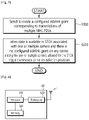
- FIG. 5 shows an example covered by the claims of triggering TX carrier (re-) selection according to an implementation of the present disclosure. According to this example covered by the claims, a new triggering condition may be implemented for TX carrier (re-) selection.
- step S500 the UE selects to create a configured sidelink grant corresponding to transmissions of multiple MAC PDUs.
- step S510 if data is available in a STCH associated with one or multiple carriers and if there is no configured sidelink grant on any carrier, among the one or multiple carriers, allowed for the STCH, then the UE triggers a TX carrier (re-)selection procedure.
- the above technique may be performed, for example, by a MAC entity of a UE.
- the MAC entity may be configured by an upper layer to transmit using pools of resources in the one or multiple carriers based on sensing, or partial sensing, or random selection.
- the upper layer may be, for example, an RRC layer of the UE.
- the data available in the STCH is associated with the one or multiple carriers, and where there is no configured sidelink grant on any carrier allowed for the STCH, then this indicates that the data available in the STCH is not associated with currently selected carrier among the one or multiple carriers.
- the association between the STCH and the one or multiple carriers may be configured by a network and/or may be pre-configured.
- the STCH is allowed to be transmitted in at least one carrier among the one or multiple carriers based on CBR and/or PPPP of the STCH.
- a new triggering condition for TX carrier (re-)selection is implemented.
- an upper layer configures multiple carriers for a first V2X service, and where the MAC entity selects a particular carrier among those multiple carriers. If new data for a second V2X service is available in a logical channel which is not associated with the particular carrier that is selected by the MAC entity, then the TX carrier (re-) selection is triggered, and a new carrier for the second V2X service can be selected.
- TX carrier (re-)selection for V2X sidelink communication is performed as follows. It is assumed that each logical channel may be mapped to each carrier or that there may be mapping between carrier(s) and service.
- the mapping between a logical channel and a carrier may be configured by the network or may be pre-configured. For example, in some implementations, the mapping may be compliant with one or more 3GPP technical standards, e.g., may be configured by the CBR-PPPP table (e.g., SL-CBR-PPPP-TxConfigList ) in Rel-14.
- a certain logical channel may be allowed to be transmitted in restricted carriers based on the CBR and the PPPP of the logical channel.
- the mapping between carriers and services may be configured, for example, by the core network and the upper layer (e.g., a V2X layer), which may provide the mapping information to the AS layer.
- the MAC entity satisfies the following:
- TX carrier reselection if the MAC entity has been configured by upper layers to transmit using one or multiple pools of resources on multiple carriers, and the TX carrier reselection is triggered for a carrier (i.e. TX carrier reselection):
- the MAC entity may also satisfy the following:
- sidelink grant selection and/or TX carrier (re-)selection for V2X sidelink communication may be performed as follows.
- Sidelink grants may be selected as follows for V2X sidelink communication:
- the UE may ensure that the randomly selected time and frequency resources fulfil a latency requirement.
- TX carrier (re-)selection for V2X sidelink communication is performed as follows.
- the MAC entity shall consider a CBR of a carrier to be one measured by lower layers if CBR measurement results are available, or the corresponding defaultTxConfigIndex configured by upper layers for the carrier if CBR measurement results are not available.
- the MAC entity shall:
- the MAC entity shall satisfy the following: 1> if one or more carriers are considered as the candidate carriers for TX carrier (re-)selection, then: 2> for each sidelink logical channel allowed on the carrier where data is available and TX carrier (re-)selection is triggered, select one or more carrier(s) and associated pool(s) of resources among the candidate carriers with increasing order of CBR from the lowest CBR.
- MCS modulation and coding scheme
- 64 quadrature amplitude modulation 64-QAM
- the criteria for resource reselection triggering may be modified.
- the configured sidelink grant cannot accommodate a RLC SDU by using a lower MCS between the maximum allowed MCS configured by upper layers in maxMCS-PSSCH and the maximum allowed MCS of the STCH corresponding to the RLC SDU, and if the MAC entity selects not to segment the RLC SDU, then resource reselection and/or TX carrier (re-)selection may be triggered. If an upper layer does not provide the maximum allowed MCS of the STCH corresponding to the RLC SDU, then the maximum allowed MCS of the STCH corresponding to the RLC SDU may be set to 16QAM. If the configured sidelink grant cannot accommodate the RLC SDU, then according to some implementations, it may be left for UE implementation whether to perform segmentation or sidelink resource reselection.
- the sidelink process configured for multiple transmissions may trigger resource reselection and/or TX carrier (re-)selection.
- the sidelink process configured for multiple transmissions may trigger resource reselection and/or TX carrier (re-) selection.
- the MAC entity may operate as follows.
- Sidelink grants may be selected on carrier(s) selected as follows for V2X sidelink communication: 1> if the MAC entity is configured to receive a sidelink grant dynamically on the PDCCH and data is available in STCH, then the MAC entity shall:
- the UE may ensure that the randomly selected time resources and frequency resources fulfill a latency requirement.
- the UE when a UE randomly selects the time resources and frequency resources or when the UE uses the randomly selected resource to select a set of periodic resources spaced by the resource reservation interval, then the UE should fulfil the following requirement.
- the MAC entity shall satisfy the following, for each subframe:
- hybrid automatic repeat request (HARQ) operations for sidelink communications may be performed as follows.
- the MAC entity is configured by upper layers to transmit using pool(s) of resources on one or multiple carriers, and there is one sidelink HARQ entity at the MAC entity for each carrier for transmission on SL-SCH, which maintains a number of parallel sidelink processes.
- the maximum number of transmitting sidelink processes associated with each sidelink HARQ entity is 8.
- a sidelink process may be configured for transmissions of multiple MAC PDUs.
- the maximum number of transmitting sidelink processes with each sidelink HARQ entity is 2.
- a delivered and configured sidelink grant and its associated HARQ information are associated with a sidelink process.
- the Sidelink HARQ Entity shall satisfy the following, in some implementations:
- logical channel prioritization for sidelink may be performed as follows. The logical channel prioritization procedure is applied when a new transmission is performed. Each sidelink logical channel has an associated priority which is the PPPP and also has an associated ProSe per-packet reliability (PPPR). Multiple sidelink logical channels may have the same associated priority. The mapping between priority and LCID may be left for UE implementation. If duplication is activated, then the MAC entity shall map different sidelink logical channels in duplication onto different carriers.
- the MAC entity shall, in some implementations, perform the following logical channel prioritization procedure either for each SCI transmitted in an SC period in sidelink communication, or for each SCI corresponding to a new transmission in V2X sidelink communication:
- Step 0 Select a ProSe Destination, having the sidelink logical channel with the highest priority, among the sidelink logical channels having data available for transmission; 1> For each MAC PDU associated to the SCI:
- the UE shall also follow the rules below during the scheduling procedures above:
- a reliability level (e.g., PPPR) is not considered for buffer status reporting.
- PPPR a reliability level
- an amount of data requiring higher reliability e.g., data having lower PPPR
- lower priority e.g., data having higher PPPP
- Such scenarios may result in problems in which data having higher reliability with lower priority would have a lower chance of being transmitted.
- data which has a reliability level (e.g., PPPR) that is below (and/or equal to) a threshold reliability level may trigger BSR reporting if SL data, for a sidelink logical channel of a ProSe Destination, becomes available for transmission in the RLC entity or in the PDCP entity, and if either the data belongs to a sidelink logical channel with lower PPPR than the PPPRs of the sidelink logical channels which belong to any LCG belonging to the same ProSe Destination and for which data is already available for transmission, or if there is currently no data available for transmission for any of the sidelink logical channels belonging to the same ProSe Destination.
- PPPR e.g., PPPR
- the data which has a priority level (e.g., PPPP) that is below (and/or equal to) a threshold priority level may trigger BSR reporting if SL data, for a sidelink logical channel of a ProSe Destination, becomes available for transmission in the RLC entity or in the PDCP entity and if the data belongs to a sidelink logical channel with lower PPPR than the PPPRs of the sidelink logical channels which belong to any LCG belonging to the same ProSe Destination and for which data is already available for transmission and lower than (and/or equal to) configured PPPR threshold.
- a priority level e.g., PPPP
- the network may configure the above reliability threshold (e.g., PPPR threshold) and/or priority threshold (e.g., PPPP threshold) for reporting of BSR via dedicated configuration.
- reliability threshold e.g., PPPR threshold
- priority threshold e.g., PPPP threshold
- buffer status reporting (BSR) for sidelink communication may be performed as follows.
- the sidelink buffer status reporting procedure is used to provide the serving eNB with information about the amount of sidelink data available for transmission in the SL buffers associated with the MAC entity.
- the RRC controls BSR reporting for the sidelink by configuring the two timers periodic-BSR-TimerSL and retx-BSR-TimerSL.
- Each sidelink logical channel belongs to a ProSe Destination.
- Each sidelink logical channel is allocated to an LCG depending on the priority and optionally the PPPR of the sidelink logical channel, and the mapping between LCG ID and priority and optionally the mapping between LCG ID and PPPR which are provided by upper layers in logicalChGroupInfoList.
- the LCG is defined per ProSe Destination.
- a sidelink BSR shall be triggered if any of the following events occur: 1> If the MAC entity has a configured SL-RNTI or a configured sidelink V-RNTI (SL-V-RNTI), then:
- the Buffer Status reporting procedure determines that at least one Sidelink BSR has been triggered and not cancelled, then: 1> if the MAC entity has UL resources allocated for new transmission for this TTI and the allocated UL resources can accommodate a Sidelink BSR MAC control element plus its subheader as a result of logical channel prioritization, then:
- a MAC PDU shall, in some implementations, contain at most one Sidelink BSR MAC control element, even when multiple events trigger a Sidelink BSR by the time a Sidelink BSR can be transmitted in which case the Regular Sidelink BSR and the Periodic Sidelink BSR shall have precedence over the padding Sidelink BSR.
- the MAC entity shall restart retx-BSR-TimerSL upon reception of an SL grant.
- All triggered regular Sidelink BSRs shall be cancelled in case the remaining configured SL grant(s) valid for this SC Period can accommodate all pending data available for transmission in sidelink communication or in case the remaining configured SL grant(s) valid can accommodate all pending data available for transmission in V2X sidelink communication.
- All triggered Sidelink BSRs shall be cancelled in case the MAC entity has no data available for transmission for any of the sidelink logical channels.
- All triggered Sidelink BSRs shall be cancelled when a Sidelink BSR (except for Truncated Sidelink BSR) is included in a MAC PDU for transmission. All triggered Sidelink BSRs shall be cancelled, and retx-BSR-TimerSL and periodic-BSR-TimerSL shall be stopped, when upper layers configure autonomous resource selection.
- the MAC entity shall transmit at most one Regular/ Periodic Sidelink BSR in a TTI. If the MAC entity is requested to transmit multiple MAC PDUs in a TTI, then it may include a padding Sidelink BSR in any of the MAC PDUs which do not contain a Regular/Periodic Sidelink BSR.
- All Sidelink BSRs transmitted in a TTI always reflect the buffer status after all MAC PDUs have been built for this TTI.
- Each LCG shall report at the most one buffer status value per TTI and this value shall be reported in all Sidelink BSRs reporting buffer status for this LCG.
- a Padding Sidelink BSR is not allowed to cancel a triggered Regular/Periodic Sidelink BSR.
- a Padding Sidelink BSR is triggered for a specific MAC PDU only and the trigger is cancelled when this MAC PDU has been built.
- the MAC header for SL-SCH is as follows.
- the MAC header is of variable size and consists of the following fields:
- the MAC header and subheaders are octet aligned.
- FIG. 6 shows an example of a UE according to some implementations of the present disclosure.
- the examples of the present disclosure described above for UE side may be applied to this implementation.
- this implementation may implement the implementation 1 described above.
- a UE 600 includes at least one processor such as processor 610, at least one memory such as memory 620 and a transceiver 630.
- the processor 610 may be configured to implement proposed functions, procedures and/or methods described in this description. Layers of the radio interface protocol may be implemented in the processor 610.
- the processor 610 is configured to select to create a configured sidelink grant corresponding to transmissions of multiple MAC PDUs.
- the processor 610 is configured to trigger TX carrier (re-)selection procedure.
- the processor 610 may include a MAC entity.
- the MAC entity may be configured by an upper layer to transmit using pools of resources in the one or multiple carriers based on sensing, or partial sensing, or random selection.
- the upper layer may be RRC layer of the UE.
- That the data is available in the STCH associated with the one or multiple carriers and there is no configured sidelink grant on any carrier allowed for the STCH may indicate that the data is available in the STCH not associated with currently selected carrier among the one or multiple carriers.
- the association between the STCH and the one or multiple carriers may be configured by a network and/or pre-configured.
- the STCH may be allowed to be transmitted in at least one carrier among the one or multiple carriers based on CBR and/or PPPP of the STCH.
- the memory 620 is operatively coupled with the processor 610 and stores a variety of information to operate the processor 610.
- the transceiver 630 is operatively coupled with the processor 610, and transmits and/or receives a radio signal.
- the processor 610 may include application-specific integrated circuit (ASIC), other chipset, logic circuit and/or data processing device.
- the memory 620 may include read-only memory (ROM), random access memory (RAM), flash memory, memory card, storage medium and/or other storage device.
- the transceiver 630 may include baseband circuitry to process radio frequency signals.
- modules e.g., procedures, functions, and so on
- the modules can be stored in the memory 620 and executed by the processor 610.
- the memory 620 can be implemented within the processor 610 or external to the processor 610 in which case those can be communicatively coupled to the processor 610 via various techniques as is known in the art.
- the new triggering condition TX carrier (re-)selection can be added. More specifically, even if upper layer configures multiple carriers for a first V2X service and MAC entity selects a carrier among the multiple carriers, and when new data for a second V2X service is available in a logical channel which is not associated with currently selected carrier, the TX carrier (re-)selection can be triggered, and a new carrier for the second V2X service can be selected.
- FIG. 7 shows an example of further details of a UE according to some implementations of the present disclosure.
- the examples of the present disclosure described above for UE side may be applied to this implementation.
- this implementation may implement the implementation 1 described above.
- a UE includes at least one processor such as a processor 610, a power management module 611, a battery 612, a display 613, a keypad 614, a subscriber identification module (SIM) card 615, at least one memory such as a memory 620, at least one transceiver such as a transceiver 630, one or more antennas 631, a speaker 640, and a microphone 641.
- processor such as a processor 610, a power management module 611, a battery 612, a display 613, a keypad 614, a subscriber identification module (SIM) card 615, at least one memory such as a memory 620, at least one transceiver such as a transceiver 630, one or more antennas 631, a speaker 640, and a microphone 641.
- SIM subscriber identification module
- the processor 610 may be configured to implement proposed functions, procedures and/or methods described in this description. Layers of the radio interface protocol may be implemented in the processor 610.
- the processor 610 may include ASIC, other chipset, logic circuit and/or data processing device.
- the processor 610 may be an application processor (AP).
- the processor 610 may include at least one of a digital signal processor (DSP), a central processing unit (CPU), a graphics processing unit (GPU), a modem (modulator and demodulator).
- DSP digital signal processor
- CPU central processing unit
- GPU graphics processing unit
- modem modulator and demodulator
- processor 610 may be found in SNAPDRAGON TM series of processors made by Qualcomm ® , EXYNOS TM series of processors made by Samsung ® , A series of processors made by Apple ® , HELIO TM series of processors made by MediaTek ® , ATOM TM series of processors made by Intel ® or a corresponding next generation processor.
- the processor 610 is configured to select to create a configured sidelink grant corresponding to transmissions of multiple MAC PDUs.
- the processor 610 is configured to trigger TX carrier (re-)selection procedure.
- the processor 610 may include a MAC entity.
- the MAC entity may be configured by an upper layer to transmit using pools of resources in the one or multiple carriers based on sensing, or partial sensing, or random selection.
- the upper layer may be RRC layer of the UE.
- That the data is available in the STCH associated with the one or multiple carriers and there is no configured sidelink grant on any carrier allowed for the STCH may indicate that the data is available in the STCH not associated with currently selected carrier among the one or multiple carriers.
- the association between the STCH and the one or multiple carriers may be configured by a network and/or pre-configured.
- the STCH may be allowed to be transmitted in at least one carrier among the one or multiple carriers based on CBR and/or PPPP of the STCH.
- the power management module 611 manages power for the processor 610 and/or the transceiver 630.
- the battery 612 supplies power to the power management module 611.
- the display 613 outputs results processed by the processor 610.
- the keypad 614 receives inputs to be used by the processor 610.
- the keypad 614 may be shown on the display 613.
- the SIM card 615 is an integrated circuit that is intended to securely store the international mobile subscriber identity (IMSI) number and its related key, which are used to identify and authenticate subscribers on mobile telephony devices (such as mobile phones and computers). It is also possible to store contact information on many SIM cards.
- IMSI international mobile subscriber identity
- the memory 620 is operatively coupled with the processor 610 and stores a variety of information to operate the processor 610.
- the memory 620 may include ROM, RAM, flash memory, memory card, storage medium and/or other storage device.
- modules e.g., procedures, functions, and so on
- the modules can be stored in the memory 620 and executed by the processor 610.
- the memory 620 can be implemented within the processor 610 or external to the processor 610 in which case those can be communicatively coupled to the processor 610 via various techniques as is known in the art.
- the transceiver 630 is operatively coupled with the processor 610, and transmits and/ or receives a radio signal.
- the transceiver 630 includes a transmitter and a receiver.
- the transceiver 630 may include baseband circuitry to process radio frequency signals.
- the transceiver 630 controls the one or more antennas 631 to transmit and/or receive a radio signal.
- the speaker 640 outputs sound-related results processed by the processor 610.
- the microphone 641 receives sound-related inputs to be used by the processor 610.
- the new triggering condition TX carrier (re-)selection can be added. More specifically, even if upper layer configures multiple carriers for a first V2X service and MAC entity selects a carrier among the multiple carriers, and when new data for a second V2X service is available in a logical channel which is not associated with currently selected carrier, the TX carrier (re-)selection can be triggered, and a new carrier for the second V2X service can be selected.
- FIG. 8 shows an example of a network node according to implementations of the present disclosure.
- the present disclosure described above for network side may be applied to this implementation.
- a network node 800 includes at least one processor such as processor 810, at least one memory such as memory 820 and a transceiver 830.
- the processor 810 may be configured to implement proposed functions, procedures and/or methods described in this description. Layers of the radio interface protocol may be implemented in the processor 810.
- the memory 820 is operatively coupled with the processor 810 and stores a variety of information to operate the processor 810.
- the transceiver 830 is operatively coupled with the processor 810, and transmits and/or receives a radio signal.
- the processor 810 may include ASIC, other chipset, logic circuit and/or data processing device.
- the memory 820 may include ROM, RAM, flash memory, memory card, storage medium and/or other storage device.
- the transceiver 830 may include baseband circuitry to process radio frequency signals.
- the techniques described herein can be implemented with modules (e.g., procedures, functions, and so on) that perform the functions described herein.
- the modules can be stored in the memory 820 and executed by the processor 810.
- the memory 820 can be implemented within the processor 810 or external to the processor 810 in which case those can be communicatively coupled to the processor 810 via various techniques as is known in the art.
Landscapes
- Engineering & Computer Science (AREA)
- Computer Networks & Wireless Communication (AREA)
- Signal Processing (AREA)
- Quality & Reliability (AREA)
- Mobile Radio Communication Systems (AREA)
Claims (12)
- Procédé exécuté par un dispositif sans fil dans un système de communication sans fil, le procédé consistant à :détecter que les données sont disponibles dans un canal de trafic en liaison latérale, STCH ;identifier une porteuse associée au STCH ; eteffectuer une procédure de sélection de porteuse de transmission, TX, dans laquelle la porteuse est considérée comme une ou plusieurs porteuses candidates pour la procédure de sélection de porteuse TX sur la base que :il n'est pas possible de transmettre les données dans le STCH à l'aide d'au moins une porteuse sélectionnée actuellement ; etun taux de canal occupé, CBR, de la porteuse est inférieur à un seuil CBR associé à une priorité du STCH,dans lequel le CBR de la porteuse comprend :une valeur CBR mesurée par le dispositif sans fil sur la base qu'un résultat de mesure de CBR est disponible pour la porteuse ; etune valeur configurée pour un réseau pour la porteuse basée sur le fait que le résultat de mesure de CBR n'est pas disponible pour la porteuse.
- Procédé selon la revendication 1, dans lequel le procédé est exécuté par une entité de contrôle d'accès au support, MAC, du dispositif sans fil.
- Procédé selon la revendication 2, dans lequel l'entité MAC du dispositif sans fil est configurée par une couche supérieure du dispositif sans fil pour transmettre à l'aide de groupes de ressources dans la porteuse en fonction de la détection ou de la détection partielle ou de la sélection aléatoire.
- Procédé selon la revendication 3, dans lequel la couche supérieure du dispositif sans fil est une couche de gestion des ressources radio, RRC, du dispositif sans fil.
- Procédé selon la revendication 1, dans lequel une association entre le STCH et la porteuse est configurée par au moins l'un parmi un réseau ou une préconfiguration.
- Procédé selon la revendication 5, dans lequel le STCH est autorisé à être transmis dans au moins une porteuse parmi la porteuse en fonction d'au moins un CBR ou une priorité par paquet, PPPP, de services basés sur la proximité, ProSe, du STCH.
- Procédé selon la revendication 1, consistant en outre à :
transmettre le STCH sur la porteuse après la procédure de sélection de porteuse TX. - Procédé selon la revendication 1, dans lequel le dispositif sans fil est en communication avec au moins l'un parmi un équipement utilisateur, UE, un réseau, ou des véhicules autonomes autre que le dispositif sans fil.
- Appareil (600, 800) comprenant.au moins une mémoire (620, 820) ; etau moins un processeur (610, 810) pouvant être connecté fonctionnellement à ladite mémoire et mémorisant des instructions qui, lorsqu'elles sont exécutées par ledit processeur, effectuent les opérations consistant à :
détecter que les données sont disponibles dans un canal de trafic en liaison latérale, STCH ;identifier une porteuse associée au STCH ; eteffectuer une procédure de sélection de porteuse de transmission, TX, dans laquelle la porteuse est considérée comme une ou plusieurs porteuses candidates pour la procédure de sélection de porteuse TX sur la base que :il n'est pas possible de transmettre les données dans le STCH à l'aide d'au moins une porteuse sélectionnée actuellement ; etun taux de canal occupé, CBR, de la porteuse est inférieur à un seuil CBR associé à une priorité du STCH,dans lequel le CBR de la porteuse comprend :une valeur CBR mesurée par le dispositif sans fil sur la base qu'un résultat de mesure de CBR est disponible pour la porteuse ; etune valeur configurée pour un réseau pour la porteuse basée sur le fait que le résultat de mesure de CBR n'est pas disponible pour la porteuse. - Appareil (600, 900) selon la revendication 9, dans lequel les opérations sont effectuées par une entité de contrôle d'accès au support, MAC, du dispositif sans fil.
- Appareil (600, 800) la revendication 10, dans lequel l'entité MAC du dispositif sans fil est configurée par une couche supérieure du dispositif sans fil pour transmettre à l'aide de groupes de ressources dans la porteuse en fonction de la détection ou de la détection partielle ou de la sélection aléatoire.
- Appareil (600, 800) la revendication 11, dans lequel la couche supérieure du dispositif sans fil est une couche de gestion des ressources radio, RRC, du dispositif sans fil.
Applications Claiming Priority (2)
| Application Number | Priority Date | Filing Date | Title |
|---|---|---|---|
| US201862668772P | 2018-05-08 | 2018-05-08 | |
| PCT/KR2019/005417 WO2019216617A1 (fr) | 2018-05-08 | 2019-05-07 | Procédé et appareil pour déclencher une sélection de porteuse de transmission dans un système de communications sans fil |
Publications (3)
| Publication Number | Publication Date |
|---|---|
| EP3747225A1 EP3747225A1 (fr) | 2020-12-09 |
| EP3747225A4 EP3747225A4 (fr) | 2021-01-27 |
| EP3747225B1 true EP3747225B1 (fr) | 2022-07-06 |
Family
ID=68464473
Family Applications (1)
| Application Number | Title | Priority Date | Filing Date |
|---|---|---|---|
| EP19800811.2A Active EP3747225B1 (fr) | 2018-05-08 | 2019-05-07 | Procédé et appareil pour déclencher une sélection de porteuse de transmission dans un système de communications sans fil |
Country Status (6)
| Country | Link |
|---|---|
| US (2) | US11297681B2 (fr) |
| EP (1) | EP3747225B1 (fr) |
| JP (1) | JP7087089B2 (fr) |
| KR (1) | KR20200141021A (fr) |
| CN (1) | CN111264080B (fr) |
| WO (1) | WO2019216617A1 (fr) |
Families Citing this family (14)
| Publication number | Priority date | Publication date | Assignee | Title |
|---|---|---|---|---|
| EP3244677B1 (fr) * | 2016-05-13 | 2020-04-29 | Panasonic Intellectual Property Corporation of America | Mécanisme amélioré de mise en oeuvre de qualité de service de communication de véhicule |
| WO2018084600A1 (fr) | 2016-11-03 | 2018-05-11 | 삼성전자 주식회사 | Procédé et dispositif permettant de prendre en charge différents services dans un système de communication mobile |
| US20220338204A1 (en) * | 2018-10-31 | 2022-10-20 | Lg Electronics Inc. | Method and apparatus for performing communication on basis of one or more frequencies |
| US11224007B2 (en) * | 2018-11-19 | 2022-01-11 | Huawei Technologies Co., Ltd. | System and method for supporting sidelink radio bearers |
| WO2020193342A1 (fr) * | 2019-03-27 | 2020-10-01 | Telefonaktiebolaget Lm Ericsson (Publ) | Procédés de gestion de sr/bsr sl |
| CN116113024A (zh) * | 2019-06-10 | 2023-05-12 | 上海朗帛通信技术有限公司 | 一种被用于无线通信的节点中的方法和装置 |
| WO2021030955A1 (fr) * | 2019-08-16 | 2021-02-25 | 华为技术有限公司 | Procédé et appareil de traitement de communication |
| CN112469023B (zh) * | 2019-09-06 | 2023-06-06 | 维沃移动通信有限公司 | 一种消息传输方法和终端 |
| KR20210092907A (ko) * | 2020-01-17 | 2021-07-27 | 주식회사 아이티엘 | 무선 통신 시스템에서 사이드링크 주파수 자원 선택 방법 및 장치 |
| WO2021159278A1 (fr) * | 2020-02-11 | 2021-08-19 | Oppo广东移动通信有限公司 | Procédé de sélection d'une ressource, dispositif terminal et support de stockage |
| CN115516883A (zh) * | 2020-06-27 | 2022-12-23 | 日本电气株式会社 | 用于通信的方法、终端设备和计算机可读介质 |
| US20230239902A1 (en) * | 2020-08-28 | 2023-07-27 | Qualcomm Incorporated | Prioritized channel access for sidelink communication in shared channel |
| EP4176684A1 (fr) * | 2021-05-10 | 2023-05-10 | ZTE Corporation | Procédé, dispositif et système pour une sélection de ressources de liaison latérale |
| US20230087091A1 (en) * | 2021-09-17 | 2023-03-23 | Qualcomm Incorporated | Techniques for data multiplexing based on packet delay |
Family Cites Families (12)
| Publication number | Priority date | Publication date | Assignee | Title |
|---|---|---|---|---|
| EP3051736B1 (fr) * | 2015-01-30 | 2020-04-29 | Panasonic Intellectual Property Corporation of America | Établissement de priorités dans la procédure de hiérarchisation de canaux logiques sur des communications directes ProSe |
| EP3148283A1 (fr) | 2015-09-25 | 2017-03-29 | ASUSTek Computer Inc. | Procédé et appareil de réduction du surdébit de signalisation dans un réseau de communication sans fil |
| EP3223575B1 (fr) * | 2015-11-19 | 2019-06-12 | ASUSTek Computer Inc. | Procédés et appareil pour commuter une interface de communication dans un système de communications sans fil |
| CN106998575B (zh) * | 2016-01-22 | 2020-09-29 | 株式会社Kt | 用于执行v2x通信的用户设备的移动性的控制方法及其装置 |
| WO2017150959A1 (fr) * | 2016-03-04 | 2017-09-08 | 엘지전자 주식회사 | Procédé de sélection de ressources de transmission v2x implémenté par un terminal dans un système de communication sans fil et terminal l'utilisant |
| WO2018030832A1 (fr) * | 2016-08-12 | 2018-02-15 | 엘지전자 주식회사 | Procédé et appareil permettant à un équipement d'utilisateur de resélectionner indépendamment une ressource sur la base d'un compteur dans un système de communication sans fil |
| JP6644947B2 (ja) * | 2016-09-30 | 2020-02-12 | エルジー エレクトロニクス インコーポレイティド | 無線通信システムにおける優先順位に基づいて端末自体的にリソースを再選択する方法及び装置 |
| EP3574694A4 (fr) * | 2017-03-24 | 2021-04-14 | Samsung Electronics Co., Ltd. | Procédé de sélection de ressource dans une communication de véhicule à tout et appareil associé |
| BR112019021276A2 (pt) * | 2017-05-04 | 2020-05-19 | Panasonic Ip Corp America | equipamento do usuário e método para o mesmo |
| WO2019064228A2 (fr) * | 2017-09-27 | 2019-04-04 | Telefonaktiebolaget Lm Ericsson (Publ) | Procédés pour permettre des transmissions à porteuses multiples de liaison latérale |
| KR20200040904A (ko) * | 2017-10-06 | 2020-04-20 | 엘지전자 주식회사 | 무선 통신 시스템에서 채널 사용률을 기반으로 반송파 재선택을 지원하는 방법 및 장치 |
| US11166292B2 (en) * | 2018-12-20 | 2021-11-02 | Asustek Computer Inc. | Method and apparatus for handling collision between sidelink feedback and sidelink data in a wireless communication system |
-
2019
- 2019-05-07 KR KR1020207018947A patent/KR20200141021A/ko active Search and Examination
- 2019-05-07 WO PCT/KR2019/005417 patent/WO2019216617A1/fr unknown
- 2019-05-07 CN CN201980005036.XA patent/CN111264080B/zh active Active
- 2019-05-07 EP EP19800811.2A patent/EP3747225B1/fr active Active
- 2019-05-07 JP JP2020542302A patent/JP7087089B2/ja active Active
- 2019-05-08 US US16/406,599 patent/US11297681B2/en active Active
-
2022
- 2022-02-08 US US17/667,160 patent/US11700666B2/en active Active
Also Published As
| Publication number | Publication date |
|---|---|
| CN111264080B (zh) | 2023-09-29 |
| CN111264080A (zh) | 2020-06-09 |
| US20190350045A1 (en) | 2019-11-14 |
| US20220167459A1 (en) | 2022-05-26 |
| WO2019216617A1 (fr) | 2019-11-14 |
| JP2021512552A (ja) | 2021-05-13 |
| JP7087089B2 (ja) | 2022-06-20 |
| US11297681B2 (en) | 2022-04-05 |
| US11700666B2 (en) | 2023-07-11 |
| KR20200141021A (ko) | 2020-12-17 |
| EP3747225A4 (fr) | 2021-01-27 |
| EP3747225A1 (fr) | 2020-12-09 |
Similar Documents
| Publication | Publication Date | Title |
|---|---|---|
| EP3747225B1 (fr) | Procédé et appareil pour déclencher une sélection de porteuse de transmission dans un système de communications sans fil | |
| JP7186763B2 (ja) | 無線通信システムにおいて複数の搬送波上でサイドリンク送信を行うための方法及び装置 | |
| US11219035B2 (en) | Method and apparatus for deprioritizing duplicated packet transmission in wireless communication system | |
| CN110831202B (zh) | 针对多个装置到装置资源池分配资源的方法和设备 | |
| US11051304B2 (en) | Method and apparatus for selecting carrier for sidelink transmission in wireless communication system | |
| US11457429B2 (en) | Method for selecting carriers and device supporting the same | |
| CN107950047B (zh) | 用于在d2d通信系统中执行缓冲器状态报告的方法及其装置 | |
| US11350309B2 (en) | Method and apparatus for deprioritizing packet transmission based on reliability level or congestion level in wireless communication system | |
| EP3120469B1 (fr) | Procédé et appareil d'indication d'informations d2d dans un système de communication sans fil | |
| US20200287665A1 (en) | Method and apparatus for flushing harq buffer in wireless communication system | |
| EP3649817B1 (fr) | Procédé et appareil permettant d'attribuer des ressources basées sur une porteuse d'ancrage dans un système de communication sans fil | |
| KR20190051894A (ko) | V2x 송신을 위한 서비스 품질의 개선된 지원 | |
| EP3354061B1 (fr) | Procédé pour transmettre un rapport d'état de mémoire tampon dans un système de communication d2d et dispositif associé | |
| US11044651B2 (en) | Method and apparatus for supporting carrier reselection based on channel busy ratio in wireless communication system | |
| US10939455B2 (en) | Method for allocating priorities to a logical channel group implicitly in a D2D communication system and device therefor | |
| US10805832B2 (en) | Method and apparatus for handling coexistence with DSRC carrier in wireless communication system | |
| CN110710313A (zh) | 选择载波的方法和设备 |
Legal Events
| Date | Code | Title | Description |
|---|---|---|---|
| STAA | Information on the status of an ep patent application or granted ep patent |
Free format text: STATUS: THE INTERNATIONAL PUBLICATION HAS BEEN MADE |
|
| PUAI | Public reference made under article 153(3) epc to a published international application that has entered the european phase |
Free format text: ORIGINAL CODE: 0009012 |
|
| STAA | Information on the status of an ep patent application or granted ep patent |
Free format text: STATUS: REQUEST FOR EXAMINATION WAS MADE |
|
| 17P | Request for examination filed |
Effective date: 20200903 |
|
| AK | Designated contracting states |
Kind code of ref document: A1 Designated state(s): AL AT BE BG CH CY CZ DE DK EE ES FI FR GB GR HR HU IE IS IT LI LT LU LV MC MK MT NL NO PL PT RO RS SE SI SK SM TR |
|
| AX | Request for extension of the european patent |
Extension state: BA ME |
|
| A4 | Supplementary search report drawn up and despatched |
Effective date: 20210112 |
|
| RIC1 | Information provided on ipc code assigned before grant |
Ipc: H04W 80/02 20090101ALN20201221BHEP Ipc: H04W 36/00 20090101AFI20201221BHEP Ipc: H04W 76/14 20180101ALI20201221BHEP Ipc: H04L 5/00 20060101ALN20201221BHEP Ipc: H04W 72/14 20090101ALI20201221BHEP |
|
| STAA | Information on the status of an ep patent application or granted ep patent |
Free format text: STATUS: EXAMINATION IS IN PROGRESS |
|
| DAV | Request for validation of the european patent (deleted) | ||
| DAX | Request for extension of the european patent (deleted) | ||
| 17Q | First examination report despatched |
Effective date: 20210716 |
|
| REG | Reference to a national code |
Ref country code: DE Ref legal event code: R079 Ref document number: 602019016810 Country of ref document: DE Free format text: PREVIOUS MAIN CLASS: H04W0072020000 Ipc: H04W0036000000 |
|
| RIC1 | Information provided on ipc code assigned before grant |
Ipc: H04W 80/02 20090101ALN20211110BHEP Ipc: H04L 5/00 20060101ALN20211110BHEP Ipc: H04W 76/14 20180101ALI20211110BHEP Ipc: H04W 72/14 20090101ALI20211110BHEP Ipc: H04W 36/00 20090101AFI20211110BHEP |
|
| GRAP | Despatch of communication of intention to grant a patent |
Free format text: ORIGINAL CODE: EPIDOSNIGR1 |
|
| STAA | Information on the status of an ep patent application or granted ep patent |
Free format text: STATUS: GRANT OF PATENT IS INTENDED |
|
| INTG | Intention to grant announced |
Effective date: 20211223 |
|
| GRAS | Grant fee paid |
Free format text: ORIGINAL CODE: EPIDOSNIGR3 |
|
| GRAA | (expected) grant |
Free format text: ORIGINAL CODE: 0009210 |
|
| STAA | Information on the status of an ep patent application or granted ep patent |
Free format text: STATUS: THE PATENT HAS BEEN GRANTED |
|
| AK | Designated contracting states |
Kind code of ref document: B1 Designated state(s): AL AT BE BG CH CY CZ DE DK EE ES FI FR GB GR HR HU IE IS IT LI LT LU LV MC MK MT NL NO PL PT RO RS SE SI SK SM TR |
|
| REG | Reference to a national code |
Ref country code: AT Ref legal event code: REF Ref document number: 1503757 Country of ref document: AT Kind code of ref document: T Effective date: 20220715 Ref country code: CH Ref legal event code: EP |
|
| REG | Reference to a national code |
Ref country code: DE Ref legal event code: R096 Ref document number: 602019016810 Country of ref document: DE |
|
| REG | Reference to a national code |
Ref country code: IE Ref legal event code: FG4D |
|
| REG | Reference to a national code |
Ref country code: LT Ref legal event code: MG9D |
|
| REG | Reference to a national code |
Ref country code: NL Ref legal event code: MP Effective date: 20220706 |
|
| PG25 | Lapsed in a contracting state [announced via postgrant information from national office to epo] |
Ref country code: SE Free format text: LAPSE BECAUSE OF FAILURE TO SUBMIT A TRANSLATION OF THE DESCRIPTION OR TO PAY THE FEE WITHIN THE PRESCRIBED TIME-LIMIT Effective date: 20220706 Ref country code: RS Free format text: LAPSE BECAUSE OF FAILURE TO SUBMIT A TRANSLATION OF THE DESCRIPTION OR TO PAY THE FEE WITHIN THE PRESCRIBED TIME-LIMIT Effective date: 20220706 Ref country code: PT Free format text: LAPSE BECAUSE OF FAILURE TO SUBMIT A TRANSLATION OF THE DESCRIPTION OR TO PAY THE FEE WITHIN THE PRESCRIBED TIME-LIMIT Effective date: 20221107 Ref country code: NO Free format text: LAPSE BECAUSE OF FAILURE TO SUBMIT A TRANSLATION OF THE DESCRIPTION OR TO PAY THE FEE WITHIN THE PRESCRIBED TIME-LIMIT Effective date: 20221006 Ref country code: NL Free format text: LAPSE BECAUSE OF FAILURE TO SUBMIT A TRANSLATION OF THE DESCRIPTION OR TO PAY THE FEE WITHIN THE PRESCRIBED TIME-LIMIT Effective date: 20220706 Ref country code: LV Free format text: LAPSE BECAUSE OF FAILURE TO SUBMIT A TRANSLATION OF THE DESCRIPTION OR TO PAY THE FEE WITHIN THE PRESCRIBED TIME-LIMIT Effective date: 20220706 Ref country code: LT Free format text: LAPSE BECAUSE OF FAILURE TO SUBMIT A TRANSLATION OF THE DESCRIPTION OR TO PAY THE FEE WITHIN THE PRESCRIBED TIME-LIMIT Effective date: 20220706 Ref country code: FI Free format text: LAPSE BECAUSE OF FAILURE TO SUBMIT A TRANSLATION OF THE DESCRIPTION OR TO PAY THE FEE WITHIN THE PRESCRIBED TIME-LIMIT Effective date: 20220706 Ref country code: ES Free format text: LAPSE BECAUSE OF FAILURE TO SUBMIT A TRANSLATION OF THE DESCRIPTION OR TO PAY THE FEE WITHIN THE PRESCRIBED TIME-LIMIT Effective date: 20220706 |
|
| REG | Reference to a national code |
Ref country code: AT Ref legal event code: MK05 Ref document number: 1503757 Country of ref document: AT Kind code of ref document: T Effective date: 20220706 |
|
| PG25 | Lapsed in a contracting state [announced via postgrant information from national office to epo] |
Ref country code: PL Free format text: LAPSE BECAUSE OF FAILURE TO SUBMIT A TRANSLATION OF THE DESCRIPTION OR TO PAY THE FEE WITHIN THE PRESCRIBED TIME-LIMIT Effective date: 20220706 Ref country code: IS Free format text: LAPSE BECAUSE OF FAILURE TO SUBMIT A TRANSLATION OF THE DESCRIPTION OR TO PAY THE FEE WITHIN THE PRESCRIBED TIME-LIMIT Effective date: 20221106 Ref country code: HR Free format text: LAPSE BECAUSE OF FAILURE TO SUBMIT A TRANSLATION OF THE DESCRIPTION OR TO PAY THE FEE WITHIN THE PRESCRIBED TIME-LIMIT Effective date: 20220706 Ref country code: GR Free format text: LAPSE BECAUSE OF FAILURE TO SUBMIT A TRANSLATION OF THE DESCRIPTION OR TO PAY THE FEE WITHIN THE PRESCRIBED TIME-LIMIT Effective date: 20221007 |
|
| REG | Reference to a national code |
Ref country code: DE Ref legal event code: R097 Ref document number: 602019016810 Country of ref document: DE |
|
| PG25 | Lapsed in a contracting state [announced via postgrant information from national office to epo] |
Ref country code: SM Free format text: LAPSE BECAUSE OF FAILURE TO SUBMIT A TRANSLATION OF THE DESCRIPTION OR TO PAY THE FEE WITHIN THE PRESCRIBED TIME-LIMIT Effective date: 20220706 Ref country code: RO Free format text: LAPSE BECAUSE OF FAILURE TO SUBMIT A TRANSLATION OF THE DESCRIPTION OR TO PAY THE FEE WITHIN THE PRESCRIBED TIME-LIMIT Effective date: 20220706 Ref country code: DK Free format text: LAPSE BECAUSE OF FAILURE TO SUBMIT A TRANSLATION OF THE DESCRIPTION OR TO PAY THE FEE WITHIN THE PRESCRIBED TIME-LIMIT Effective date: 20220706 Ref country code: CZ Free format text: LAPSE BECAUSE OF FAILURE TO SUBMIT A TRANSLATION OF THE DESCRIPTION OR TO PAY THE FEE WITHIN THE PRESCRIBED TIME-LIMIT Effective date: 20220706 Ref country code: AT Free format text: LAPSE BECAUSE OF FAILURE TO SUBMIT A TRANSLATION OF THE DESCRIPTION OR TO PAY THE FEE WITHIN THE PRESCRIBED TIME-LIMIT Effective date: 20220706 |
|
| PLBE | No opposition filed within time limit |
Free format text: ORIGINAL CODE: 0009261 |
|
| STAA | Information on the status of an ep patent application or granted ep patent |
Free format text: STATUS: NO OPPOSITION FILED WITHIN TIME LIMIT |
|
| PG25 | Lapsed in a contracting state [announced via postgrant information from national office to epo] |
Ref country code: SK Free format text: LAPSE BECAUSE OF FAILURE TO SUBMIT A TRANSLATION OF THE DESCRIPTION OR TO PAY THE FEE WITHIN THE PRESCRIBED TIME-LIMIT Effective date: 20220706 Ref country code: EE Free format text: LAPSE BECAUSE OF FAILURE TO SUBMIT A TRANSLATION OF THE DESCRIPTION OR TO PAY THE FEE WITHIN THE PRESCRIBED TIME-LIMIT Effective date: 20220706 |
|
| 26N | No opposition filed |
Effective date: 20230411 |
|
| PG25 | Lapsed in a contracting state [announced via postgrant information from national office to epo] |
Ref country code: AL Free format text: LAPSE BECAUSE OF FAILURE TO SUBMIT A TRANSLATION OF THE DESCRIPTION OR TO PAY THE FEE WITHIN THE PRESCRIBED TIME-LIMIT Effective date: 20220706 |
|
| P01 | Opt-out of the competence of the unified patent court (upc) registered |
Effective date: 20230527 |
|
| PGFP | Annual fee paid to national office [announced via postgrant information from national office to epo] |
Ref country code: FR Payment date: 20230405 Year of fee payment: 5 Ref country code: DE Payment date: 20230405 Year of fee payment: 5 |
|
| PG25 | Lapsed in a contracting state [announced via postgrant information from national office to epo] |
Ref country code: SI Free format text: LAPSE BECAUSE OF FAILURE TO SUBMIT A TRANSLATION OF THE DESCRIPTION OR TO PAY THE FEE WITHIN THE PRESCRIBED TIME-LIMIT Effective date: 20220706 |
|
| PGFP | Annual fee paid to national office [announced via postgrant information from national office to epo] |
Ref country code: GB Payment date: 20230405 Year of fee payment: 5 |
|
| REG | Reference to a national code |
Ref country code: CH Ref legal event code: PL |
|
| PG25 | Lapsed in a contracting state [announced via postgrant information from national office to epo] |
Ref country code: MC Free format text: LAPSE BECAUSE OF FAILURE TO SUBMIT A TRANSLATION OF THE DESCRIPTION OR TO PAY THE FEE WITHIN THE PRESCRIBED TIME-LIMIT Effective date: 20220706 |
|
| REG | Reference to a national code |
Ref country code: BE Ref legal event code: MM Effective date: 20230531 |
|
| PG25 | Lapsed in a contracting state [announced via postgrant information from national office to epo] |
Ref country code: MC Free format text: LAPSE BECAUSE OF FAILURE TO SUBMIT A TRANSLATION OF THE DESCRIPTION OR TO PAY THE FEE WITHIN THE PRESCRIBED TIME-LIMIT Effective date: 20220706 Ref country code: LU Free format text: LAPSE BECAUSE OF NON-PAYMENT OF DUE FEES Effective date: 20230507 Ref country code: LI Free format text: LAPSE BECAUSE OF NON-PAYMENT OF DUE FEES Effective date: 20230531 Ref country code: IT Free format text: LAPSE BECAUSE OF FAILURE TO SUBMIT A TRANSLATION OF THE DESCRIPTION OR TO PAY THE FEE WITHIN THE PRESCRIBED TIME-LIMIT Effective date: 20220706 Ref country code: CH Free format text: LAPSE BECAUSE OF NON-PAYMENT OF DUE FEES Effective date: 20230531 |
|
| REG | Reference to a national code |
Ref country code: IE Ref legal event code: MM4A |
|
| PG25 | Lapsed in a contracting state [announced via postgrant information from national office to epo] |
Ref country code: IE Free format text: LAPSE BECAUSE OF NON-PAYMENT OF DUE FEES Effective date: 20230507 |
|
| PG25 | Lapsed in a contracting state [announced via postgrant information from national office to epo] |
Ref country code: IE Free format text: LAPSE BECAUSE OF NON-PAYMENT OF DUE FEES Effective date: 20230507 |