EP3120469B1 - Procédé et appareil d'indication d'informations d2d dans un système de communication sans fil - Google Patents
Procédé et appareil d'indication d'informations d2d dans un système de communication sans fil Download PDFInfo
- Publication number
- EP3120469B1 EP3120469B1 EP15765005.2A EP15765005A EP3120469B1 EP 3120469 B1 EP3120469 B1 EP 3120469B1 EP 15765005 A EP15765005 A EP 15765005A EP 3120469 B1 EP3120469 B1 EP 3120469B1
- Authority
- EP
- European Patent Office
- Prior art keywords
- communication
- prose
- rrc
- scheduling
- configuration
- Prior art date
- Legal status (The legal status is an assumption and is not a legal conclusion. Google has not performed a legal analysis and makes no representation as to the accuracy of the status listed.)
- Active
Links
- 238000004891 communication Methods 0.000 title claims description 73
- 238000000034 method Methods 0.000 title claims description 32
- 230000005540 biological transmission Effects 0.000 description 63
- 230000006870 function Effects 0.000 description 30
- 230000011664 signaling Effects 0.000 description 11
- 238000005516 engineering process Methods 0.000 description 10
- 238000013468 resource allocation Methods 0.000 description 10
- 238000010586 diagram Methods 0.000 description 9
- 230000015654 memory Effects 0.000 description 9
- 238000012546 transfer Methods 0.000 description 9
- 238000007726 management method Methods 0.000 description 8
- 238000013507 mapping Methods 0.000 description 4
- 230000000737 periodic effect Effects 0.000 description 4
- 230000006978 adaptation Effects 0.000 description 3
- 230000001413 cellular effect Effects 0.000 description 3
- 230000008859 change Effects 0.000 description 3
- 230000003993 interaction Effects 0.000 description 3
- 238000005259 measurement Methods 0.000 description 3
- 238000013475 authorization Methods 0.000 description 2
- 230000006835 compression Effects 0.000 description 2
- 238000007906 compression Methods 0.000 description 2
- 230000000977 initiatory effect Effects 0.000 description 2
- 230000007774 longterm Effects 0.000 description 2
- 230000008569 process Effects 0.000 description 2
- 230000004913 activation Effects 0.000 description 1
- 230000002860 competitive effect Effects 0.000 description 1
- 238000013500 data storage Methods 0.000 description 1
- 230000003247 decreasing effect Effects 0.000 description 1
- 230000001419 dependent effect Effects 0.000 description 1
- 230000000694 effects Effects 0.000 description 1
- 238000001914 filtration Methods 0.000 description 1
- 238000007689 inspection Methods 0.000 description 1
- 238000010295 mobile communication Methods 0.000 description 1
- 230000006855 networking Effects 0.000 description 1
- 238000012545 processing Methods 0.000 description 1
- 230000004044 response Effects 0.000 description 1
- 238000001228 spectrum Methods 0.000 description 1
- 230000008685 targeting Effects 0.000 description 1
- 238000013519 translation Methods 0.000 description 1
Images


Classifications
-
- H—ELECTRICITY
- H04—ELECTRIC COMMUNICATION TECHNIQUE
- H04W—WIRELESS COMMUNICATION NETWORKS
- H04W48/00—Access restriction; Network selection; Access point selection
- H04W48/08—Access restriction or access information delivery, e.g. discovery data delivery
- H04W48/12—Access restriction or access information delivery, e.g. discovery data delivery using downlink control channel
-
- H—ELECTRICITY
- H04—ELECTRIC COMMUNICATION TECHNIQUE
- H04L—TRANSMISSION OF DIGITAL INFORMATION, e.g. TELEGRAPHIC COMMUNICATION
- H04L67/00—Network arrangements or protocols for supporting network services or applications
- H04L67/50—Network services
- H04L67/51—Discovery or management thereof, e.g. service location protocol [SLP] or web services
-
- H—ELECTRICITY
- H04—ELECTRIC COMMUNICATION TECHNIQUE
- H04L—TRANSMISSION OF DIGITAL INFORMATION, e.g. TELEGRAPHIC COMMUNICATION
- H04L67/00—Network arrangements or protocols for supporting network services or applications
- H04L67/01—Protocols
- H04L67/10—Protocols in which an application is distributed across nodes in the network
- H04L67/104—Peer-to-peer [P2P] networks
- H04L67/1061—Peer-to-peer [P2P] networks using node-based peer discovery mechanisms
-
- H—ELECTRICITY
- H04—ELECTRIC COMMUNICATION TECHNIQUE
- H04L—TRANSMISSION OF DIGITAL INFORMATION, e.g. TELEGRAPHIC COMMUNICATION
- H04L67/00—Network arrangements or protocols for supporting network services or applications
- H04L67/50—Network services
- H04L67/60—Scheduling or organising the servicing of application requests, e.g. requests for application data transmissions using the analysis and optimisation of the required network resources
- H04L67/61—Scheduling or organising the servicing of application requests, e.g. requests for application data transmissions using the analysis and optimisation of the required network resources taking into account QoS or priority requirements
-
- H—ELECTRICITY
- H04—ELECTRIC COMMUNICATION TECHNIQUE
- H04L—TRANSMISSION OF DIGITAL INFORMATION, e.g. TELEGRAPHIC COMMUNICATION
- H04L67/00—Network arrangements or protocols for supporting network services or applications
- H04L67/50—Network services
- H04L67/60—Scheduling or organising the servicing of application requests, e.g. requests for application data transmissions using the analysis and optimisation of the required network resources
- H04L67/62—Establishing a time schedule for servicing the requests
-
- H—ELECTRICITY
- H04—ELECTRIC COMMUNICATION TECHNIQUE
- H04W—WIRELESS COMMUNICATION NETWORKS
- H04W28/00—Network traffic management; Network resource management
- H04W28/02—Traffic management, e.g. flow control or congestion control
- H04W28/0268—Traffic management, e.g. flow control or congestion control using specific QoS parameters for wireless networks, e.g. QoS class identifier [QCI] or guaranteed bit rate [GBR]
-
- H—ELECTRICITY
- H04—ELECTRIC COMMUNICATION TECHNIQUE
- H04W—WIRELESS COMMUNICATION NETWORKS
- H04W48/00—Access restriction; Network selection; Access point selection
- H04W48/02—Access restriction performed under specific conditions
- H04W48/06—Access restriction performed under specific conditions based on traffic conditions
-
- H—ELECTRICITY
- H04—ELECTRIC COMMUNICATION TECHNIQUE
- H04W—WIRELESS COMMUNICATION NETWORKS
- H04W48/00—Access restriction; Network selection; Access point selection
- H04W48/16—Discovering, processing access restriction or access information
-
- H—ELECTRICITY
- H04—ELECTRIC COMMUNICATION TECHNIQUE
- H04W—WIRELESS COMMUNICATION NETWORKS
- H04W76/00—Connection management
- H04W76/10—Connection setup
- H04W76/14—Direct-mode setup
-
- H—ELECTRICITY
- H04—ELECTRIC COMMUNICATION TECHNIQUE
- H04W—WIRELESS COMMUNICATION NETWORKS
- H04W8/00—Network data management
- H04W8/005—Discovery of network devices, e.g. terminals
-
- H—ELECTRICITY
- H04—ELECTRIC COMMUNICATION TECHNIQUE
- H04W—WIRELESS COMMUNICATION NETWORKS
- H04W84/00—Network topologies
- H04W84/18—Self-organising networks, e.g. ad-hoc networks or sensor networks
-
- H—ELECTRICITY
- H04—ELECTRIC COMMUNICATION TECHNIQUE
- H04W—WIRELESS COMMUNICATION NETWORKS
- H04W36/00—Hand-off or reselection arrangements
- H04W36/03—Reselecting a link using a direct mode connection
-
- H—ELECTRICITY
- H04—ELECTRIC COMMUNICATION TECHNIQUE
- H04W—WIRELESS COMMUNICATION NETWORKS
- H04W36/00—Hand-off or reselection arrangements
- H04W36/03—Reselecting a link using a direct mode connection
- H04W36/033—Reselecting a link using a direct mode connection in pre-organised networks
-
- H—ELECTRICITY
- H04—ELECTRIC COMMUNICATION TECHNIQUE
- H04W—WIRELESS COMMUNICATION NETWORKS
- H04W48/00—Access restriction; Network selection; Access point selection
- H04W48/02—Access restriction performed under specific conditions
Definitions
- the present invention relates to wireless communications, and more particularly, to a method and apparatus for indicating device-to-device (D2D) related information in a wireless communication system.
- D2D device-to-device
- 3rd generation partnership project (3GPP) long-term evolution (LTE) is a technology for enabling high-speed packet communications.
- 3GPP 3rd generation partnership project
- LTE long-term evolution
- Many schemes have been proposed for the LTE objective including those that aim to reduce user and provider costs, improve service quality, and expand and improve coverage and system capacity.
- the 3GPP LTE requires reduced cost per bit, increased service availability, flexible use of a frequency band, a simple structure, an open interface, and adequate power consumption of a terminal as an upper-level requirement.
- Proximity is determined (“a user equipment (UE) is in proximity of another UE") when given proximity criteria are fulfilled.
- UE user equipment
- 3GPP is targeting the availability of ProSe in LTE rel-12 to enable LTE become a competitive broadband communication technology for public safety networks, used by first responders. Due to the legacy issues and budget constraints, current public safety networks are still mainly based on obsolete 2G technologies while commercial networks are rapidly migrating to LTE. This evolution gap and the desire for enhanced services have led to global attempts to upgrade existing public safety networks. Compared to commercial networks, public safety networks have much more stringent service requirements (e.g., reliability and security) and also require direct communication, especially when cellular coverage fails or is not available. This essential direct mode feature is currently missing in LTE.
- D2D device-to-device
- WO 2013/032259 A2 discloses a method for performing a hand-over to a cellular network through which devices communicate with each other in a wireless connection system for supporting communication between the devices.
- US 2013/322413 A1 discloses D2D scheduling information containing timing interval and timing of scheduling assignment and also discloses that D2D messages are exchanged at various layers, according to various protocols such as e.g. MAC or RRC.
- the present invention provides a method and apparatus for indicating device-to-device (D2D) related information in a wireless communication system.
- the present invention provides a method for indicating at least one of service type/quality of service (QoS) characteristics of D2D service/D2D configuration to a network.
- QoS quality of service
- the invention relates to a method according to claim 1, and to an apparatus according to claim 7. Further embodiments are defined in the dependent claims.
- CDMA code division multiple access
- FDMA frequency division multiple access
- TDMA time division multiple access
- OFDMA orthogonal frequency division multiple access
- SC-FDMA single carrier frequency division multiple access
- the CDMA can be implemented with a radio technology such as universal terrestrial radio access (UTRA) or CDMA-2000.
- UTRA universal terrestrial radio access
- the TDMA can be implemented with a radio technology such as global system for mobile communications (GSM)/general packet ratio service (GPRS)/enhanced data rate for GSM evolution (EDGE).
- GSM global system for mobile communications
- GPRS general packet ratio service
- EDGE enhanced data rate for GSM evolution
- the OFDMA can be implemented with a radio technology such as institute of electrical and electronics engineers (IEEE) 802.11 (Wi-Fi), IEEE 802.16 (WiMAX), IEEE 802-20, evolved UTRA (E-UTRA), etc.
- IEEE 802.16m is an evolution of IEEE 802.16e, and provides backward compatibility with an IEEE 802.16-based system.
- the UTRA is a part of a universal mobile telecommunication system (UMTS).
- 3rd generation partnership project (3GPP) long term evolution (LTE) is a part of an evolved UMTS (E-UMTS) using the E-UTRA.
- 3GPP LTE uses the OFDMA in downlink and uses the SC-FDMA in uplink.
- LTE-advance (LTE-A) is an evolution of the 3GPP LTE.
- FIG. 1 shows LTE system architecture.
- the communication network is widely deployed to provide a variety of communication services such as voice over internet protocol (VoIP) through IMS and packet data.
- VoIP voice over internet protocol
- the LTE system architecture includes one or more user equipment (UE; 10), an evolved-UMTS terrestrial radio access network (E-UTRAN) and an evolved packet core (EPC).
- the UE 10 refers to a communication equipment carried by a user.
- the UE 10 may be fixed or mobile, and may be referred to as another terminology, such as a mobile station (MS), a user terminal (UT), a subscriber station (SS), a wireless device, etc.
- MS mobile station
- UT user terminal
- SS subscriber station
- wireless device etc.
- the E-UTRAN includes one or more evolved node-B (eNB) 20, and a plurality of UEs may be located in one cell.
- the eNB 20 provides an end point of a control plane and a user plane to the UE 10.
- the eNB 20 is generally a fixed station that communicates with the UE 10 and may be referred to as another terminology, such as a base station (BS), an access point, etc.
- BS base station
- One eNB 20 may be deployed per cell.
- a downlink (DL) denotes communication from the eNB 20 to the UE
- an uplink (UL) denotes communication from the UE 10 to the eNB 20.
- a transmitter may be a part of the eNB 20, and a receiver may be a part of the UE 10.
- the transmitter may be a part of the UE 10, and the receiver may be a part of the eNB 20.
- the EPC includes a mobility management entity (MME) and a system architecture evolution (SAE) gateway (S-GW).
- MME mobility management entity
- SAE system architecture evolution gateway
- the MME/S-GW 30 may be positioned at the end of the network and connected to an external network.
- MME/S-GW 30 will be referred to herein simply as a "gateway,” but it is understood that this entity includes both the MME and S-GW.
- the MME provides various functions including non-access stratum (NAS) signaling to eNBs 20, NAS signaling security, access stratum (AS) security control, inter core network (CN) node signaling for mobility between 3GPP access networks, idle mode UE reachability (including control and execution of paging retransmission), tracking area list management (for UE in idle and active mode), packet data network (PDN) gateway (P-GW) and S-GW selection, MME selection for handovers with MME change, serving GPRS support node (SGSN) selection for handovers to 2G or 3G 3GPP access networks, roaming, authentication, bearer management functions including dedicated bearer establishment, support for public warning system (PWS) (which includes earthquake and tsunami warning system (ETWS) and commercial mobile alert system (CMAS)) message transmission.
- PWS public warning system
- ETWS earthquake and tsunami warning system
- CMAS commercial mobile alert system
- the S-GW host provides assorted functions including per-user based packet filtering (by e.g., deep packet inspection), lawful interception, UE Internet protocol (IP) address allocation, transport level packet marking in the DL, UL and DL service level charging, gating and rate enforcement, DL rate enforcement based on access point name aggregate maximum bit rate (APN-AMBR).
- per-user based packet filtering by e.g., deep packet inspection
- IP Internet protocol
- transport level packet marking in the DL transport level packet marking in the DL
- UL and DL service level charging e.g., gating and rate enforcement
- DL rate enforcement based on access point name aggregate maximum bit rate (APN-AMBR).
- APN-AMBR access point name aggregate maximum bit rate
- Interfaces for transmitting user traffic or control traffic may be used.
- the UE 10 is connected to the eNB 20 via a Uu interface.
- the eNBs 20 are connected to each other via an X2 interface.
- Neighboring eNBs may have a meshed network structure that has the X2 interface.
- a plurality of nodes may be connected between the eNB 20 and the gateway 30 via an S1 interface.
- FIG. 2 shows a block diagram of architecture of a typical E-UTRAN and a typical EPC.
- the eNB 20 may perform functions of selection for gateway 30, routing toward the gateway 30 during a radio resource control (RRC) activation, scheduling and transmitting of paging messages, scheduling and transmitting of broadcast channel (BCH) information, dynamic allocation of resources to the UEs 10 in both UL and DL, configuration and provisioning of eNB measurements, radio bearer control, radio admission control (RAC), and connection mobility control in LTE_ACTIVE state.
- gateway 30 may perform functions of paging origination, LTE_IDLE state management, ciphering of the user plane, SAE bearer control, and ciphering and integrity protection of NAS signaling.
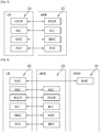
- FIG. 3 shows a block diagram of a user plane protocol stack of an LTE system.
- FIG. 4 shows a block diagram of a control plane protocol stack of an LTE system.
- Layers of a radio interface protocol between the UE and the E-UTRAN may be classified into a first layer (L1), a second layer (L2), and a third layer (L3) based on the lower three layers of the open system interconnection (OSI) model that is well-known in the communication system.
- OSI open system interconnection
- a physical (PHY) layer belongs to the L1.
- the PHY layer provides a higher layer with an information transfer service through a physical channel.
- the PHY layer is connected to a medium access control (MAC) layer, which is a higher layer of the PHY layer, through a transport channel.
- MAC medium access control
- a physical channel is mapped to the transport channel. Data between the MAC layer and the PHY layer is transferred through the transport channel.
- PHY physical
- a MAC layer, a radio link control (RLC) layer, and a packet data convergence protocol (PDCP) layer belong to the L2.
- the MAC layer provides services to the RLC layer, which is a higher layer of the MAC layer, via a logical channel.
- the MAC layer provides data transfer services on logical channels.
- the RLC layer supports the transmission of data with reliability. Meanwhile, a function of the RLC layer may be implemented with a functional block inside the MAC layer. In this case, the RLC layer may not exist.
- the PDCP layer provides a function of header compression function that reduces unnecessary control information such that data being transmitted by employing IP packets, such as IPv4 or IPv6, can be efficiently transmitted over a radio interface that has a relatively small bandwidth.
- a radio resource control (RRC) layer belongs to the L3.
- the RLC layer is located at the lowest portion of the L3, and is only defined in the control plane.
- the RRC layer controls logical channels, transport channels, and physical channels in relation to the configuration, reconfiguration, and release of radio bearers (RBs).
- the RB signifies a service provided the L2 for data transmission between the UE and E-UTRAN.
- the RLC and MAC layers may perform functions such as scheduling, automatic repeat request (ARQ), and hybrid ARQ (HARQ).
- the PDCP layer may perform the user plane functions such as header compression, integrity protection, and ciphering.
- the RLC and MAC layers may perform the same functions for the control plane.
- the RRC layer (terminated in the eNB on the network side) may perform functions such as broadcasting, paging, RRC connection management, RB control, mobility functions, and UE measurement reporting and controlling.
- the NAS control protocol (terminated in the MME of gateway on the network side) may perform functions such as a SAE bearer management, authentication, LTE_IDLE mobility handling, paging origination in LTE_IDLE, and security control for the signaling between the gateway and UE.
- FIG. 5 shows an example of a physical channel structure.
- a physical channel transfers signaling and data between PHY layer of the UE and eNB with a radio resource.
- a physical channel consists of a plurality of subframes in time domain and a plurality of subcarriers in frequency domain.
- One subframe which is 1 ms, consists of a plurality of symbols in the time domain.
- Specific symbol(s) of the subframe such as the first symbol of the subframe, may be used for a physical downlink control channel (PDCCH).
- the PDCCH carries dynamic allocated resources, such as a physical resource block (PRB) and modulation and coding scheme (MCS).
- PRB physical resource block
- MCS modulation and coding scheme
- a DL transport channel includes a broadcast channel (BCH) used for transmitting system information, a paging channel (PCH) used for paging a UE, a downlink shared channel (DL-SCH) used for transmitting user traffic or control signals, a multicast channel (MCH) used for multicast or broadcast service transmission.
- BCH broadcast channel
- PCH paging channel
- DL-SCH downlink shared channel
- MCH multicast channel
- the DL-SCH supports HARQ, dynamic link adaptation by varying the modulation, coding and transmit power, and both dynamic and semi-static resource allocation.
- the DL-SCH also may enable broadcast in the entire cell and the use of beamforming.
- a UL transport channel includes a random access channel (RACH) normally used for initial access to a cell, a uplink shared channel (UL-SCH) for transmitting user traffic or control signals, etc.
- RACH random access channel
- UL-SCH uplink shared channel
- the UL-SCH supports HARQ and dynamic link adaptation by varying the transmit power and potentially modulation and coding.
- the UL-SCH also may enable the use of beamforming.
- the logical channels are classified into control channels for transferring control plane information and traffic channels for transferring user plane information, according to a type of transmitted information. That is, a set of logical channel types is defined for different data transfer services offered by the MAC layer.
- the control channels are used for transfer of control plane information only.
- the control channels provided by the MAC layer include a broadcast control channel (BCCH), a paging control channel (PCCH), a common control channel (CCCH), a multicast control channel (MCCH) and a dedicated control channel (DCCH).
- the BCCH is a downlink channel for broadcasting system control information.
- the PCCH is a downlink channel that transfers paging information and is used when the network does not know the location cell of a UE.
- the CCCH is used by UEs having no RRC connection with the network.
- the MCCH is a point-to-multipoint downlink channel used for transmitting multimedia broadcast multicast services (MBMS) control information from the network to a UE.
- the DCCH is a point-to-point bi-directional channel used by UEs having an RRC connection that transmits dedicated control information between a UE and the network.
- Traffic channels are used for the transfer of user plane information only.
- the traffic channels provided by the MAC layer include a dedicated traffic channel (DTCH) and a multicast traffic channel (MTCH).
- DTCH dedicated traffic channel
- MTCH multicast traffic channel
- the DTCH is a point-to-point channel, dedicated to one UE for the transfer of user information and can exist in both uplink and downlink.
- the MTCH is a point-to-multipoint downlink channel for transmitting traffic data from the network to the UE.
- Uplink connections between logical channels and transport channels include the DCCH that can be mapped to the UL-SCH, the DTCH that can be mapped to the UL-SCH and the CCCH that can be mapped to the UL-SCH.
- Downlink connections between logical channels and transport channels include the BCCH that can be mapped to the BCH or DL-SCH, the PCCH that can be mapped to the PCH, the DCCH that can be mapped to the DL-SCH, and the DTCH that can be mapped to the DL-SCH, the MCCH that can be mapped to the MCH, and the MTCH that can be mapped to the MCH.
- An RRC state indicates whether an RRC layer of the UE is logically connected to an RRC layer of the E-UTRAN.
- the RRC state may be divided into two different states such as an RRC idle state (RRC_IDLE) and an RRC connected state (RRC_CONNECTED).
- RRC_IDLE the UE may receive broadcasts of system information and paging information while the UE specifies a discontinuous reception (DRX) configured by NAS, and the UE has been allocated an identification (ID) which uniquely identifies the UE in a tracking area and may perform public land mobile network (PLMN) selection and cell re-selection.
- ID identification
- PLMN public land mobile network
- the UE In RRC_CONNECTED, the UE has an E-UTRAN RRC connection and a context in the E-UTRAN, such that transmitting and/or receiving data to/from the eNB becomes possible. Also, the UE can report channel quality information and feedback information to the eNB.
- the E-UTRAN knows the cell to which the UE belongs. Therefore, the network can transmit and/or receive data to/from UE, the network can control mobility (handover and inter-radio access technologies (RAT) cell change order to GSM EDGE radio access network (GERAN) with network assisted cell change (NACC)) of the UE, and the network can perform cell measurements for a neighboring cell.
- RAT inter-radio access technologies
- GERAN GSM EDGE radio access network
- NACC network assisted cell change
- the UE specifies the paging DRX cycle. Specifically, the UE monitors a paging signal at a specific paging occasion of every UE specific paging DRX cycle.
- the paging occasion is a time interval during which a paging signal is transmitted.
- the UE has its own paging occasion.
- a paging message is transmitted over all cells belonging to the same tracking area. If the UE moves from one tracking area (TA) to another TA, the UE will send a tracking area update (TAU) message to the network to update its location.
- TAU tracking area update
- Proximity-based services are described. It may be referred to 3GPP TR 23.703 V1.0.0 (2013-12 ).
- ProSe may be a concept including a device-to-device (D2D) communication.
- D2D device-to-device
- ProSe may be used by being mixed with “D2D”.
- ProSe direct communication means a communication between two or more UEs in proximity that are ProSe-enabled, by means of user plane transmission using E-UTRA technology via a path not traversing any network node.
- ProSe-enabled UE means a UE that supports ProSe requirements and associated procedures. Unless explicitly stated otherwise, a ProSe-enabled UE refers both to a non-public safety UE and a public safety UE.
- ProSe-enabled public safety UE means a ProSe-enabled UE that also supports ProSe procedures and capabilities specific to public safety.
- ProSe-enabled non-public safety UE means a UE that supports ProSe procedures and but not capabilities specific to public safety.
- ProSe direct discovery means a procedure employed by a ProSe-enabled UE to discover other ProSe-enabled UEs in its vicinity by using only the capabilities of the two UEs with 3GPP LTE rel-12 technology.
- EPC-level ProSe discovery means a process by which the EPC determines the proximity of two ProSe-enabled UEs and informs them of their proximity.
- ProSe UE identity is a unique identity allocated by evolved packet system (EPS) which identifies the ProSe enabled UE.
- ProSe application ID is an identity identifying application related information for the ProSe enabled UE.
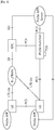
- FIG. 6 shows reference architecture for ProSe.
- the reference architecture for ProSe includes E-UTRAN, EPC, a plurality of UEs having ProSe applications, ProSe application server, and ProSe function.
- the EPC represents the E-UTRAN core network architecture.
- the EPC includes entities such as MME, S-GW, P-GW, policy and charging rules function (PCRF), home subscriber server (HSS), etc.
- the ProSe application servers are users of the ProSe capability for building the application functionality. In the public safety cases, they can be specific agencies (PSAP), or in the commercial cases social media. These applications rare defined outside the 3GPP architecture but there may be reference points towards 3GPP entities.
- the application server can communicate towards an application in the UE. Applications in the UE use the ProSe capability for building the application functionality. Example may be for communication between members of public safety groups or for social media application that requests to find buddies in proximity.
- the ProSe function in the network (as part of EPS) defined by 3GPP has a reference point towards the ProSe application server, towards the EPC and the UE.
- the functionality may include at least one of followings, but not be restricted thereto.
- Sidelink is UE to UE interface for ProSe direct communication and ProSe direct discovery.
- Sidelink comprises ProSe direct discovery and ProSe direct communication between UEs.
- Sidelink uses uplink resources and physical channel structure similar to uplink transmissions.
- Sidelink transmission uses the same basic transmission scheme as the UL transmission scheme. However, sidelink is limited to single cluster transmissions for all the sidelink physical channels. Further, sidelink uses a 1 symbol gap at the end of each sidelink sub-frame.
- FIG. 7 shows an example of mapping between sidelink transport channels and sidelink physical channels.
- a physical sidelink discovery channel (PSDCH), which carries ProSe direct discovery message from the UE, may be mapped to a sidelink discovery channel (SL-DCH).
- PSDCH physical sidelink discovery channel
- SL-DCH sidelink discovery channel
- PSSCH physical sidelink shared channel
- SL-SCH sidelink shared channel
- a physical sidelink broadcast channel which carries system and synchronization related information transmitted from the UE, may be mapped to a sidelink broadcast channel (SL-BCH).
- the SL-BCH is characterized by pre-defined transport format.
- a physical sidelink control channel (PSCCH) carries control from a UE for ProSe direct communication.
- FIG. 8 shows an example of mapping between sidelink logical channels and sidelink transport channels for ProSe direct communication.
- the SL-BCH may be mapped to a sidelink broadcast control channel (SBCCH), which is a sidelink channel for broadcasting sidelink system information from one UE to other UE(s). This channel is used only by ProSe direct communication capable UEs.
- SBCCH sidelink broadcast control channel
- the SL-SCH may be mapped to a sidelink traffic channel (STCH), which is a point-to-multipoint channel, for transfer of user information from one UE to other UEs. This channel is used only by ProSe direct communication capable UEs.
- STCH sidelink traffic channel
- ProSe direct communication is a mode of communication whereby UEs can communicate with each other directly over the PC5 interface. This communication mode is supported when the UE is served by E-UTRAN and when the UE is outside of E-UTRA coverage. Only those UEs authorized to be used for public safety operation can perform ProSe direct communication.
- SBCCH In order to perform synchronization SBCCH carries the most essential system information needed to receive other ProSe channels and signals. SBCCH along with synchronization signal is transmitted with a fixed periodicity of 40ms. When the UE is in network coverage, the contents of SBCCH are derived from the parameters signaled by the eNB. When the UE is out of coverage, if the UE selects another UE as a synchronization reference, then the content of SBCCH is derived from the received SBCCH; otherwise the UE uses pre-configured parameters. There is only one subframe every 40ms for synchronization signal and SBCCH transmission for in-coverage operation. SIB18 provides the resource information for synchronization signal and SBCCH transmission.
- the UE receives synchronization signal and SBCCH in one subframe and transmit synchronization signal and SBCCH on another subframe if UE becomes synchronization source based on defined criterion.
- the UE performs Prose direct communication on subframes defined over the duration of sidelink control period.
- the sidelink control period is the period over which resources allocated in a cell for sidelink control and sidelink data transmissions occur. Within the sidelink control period the UE sends a sidelink control followed by data.
- Sidelink control indicates a layer 1 ID and characteristics of the transmissions (e.g. MCS, location of the resource(s) over the duration of sidelink control period, timing alignment).
- the UE performs transmission and reception of Uu and PC5 with the following decreasing priority order:
- the UE supporting ProSe direct communication can operate in two modes for resource allocation.
- First is scheduled resource allocation (hereinafter, D2D mode 1), in which the UE needs to be RRC_CONNECTED in order to transmit data, and the UE requests transmission resources from the eNB.
- the eNB schedules transmission resources for transmission of sidelink control and data.
- the UE sends a scheduling request (dedicated SR or random access) to the eNB followed by a ProSe buffer status report (BSR).
- BSR ProSe buffer status report
- the eNB Based on the ProSe BSR, the eNB can determine that the UE has data for a ProSe direct communication transmission and estimate the resources needed for transmission.
- the eNB can schedule transmission resources for ProSe direct communication using configured SL-RNTI.
- Second is UE autonomous resource selection (hereinafter, D2D mode 2), in which the UE on its own selects resources from resource pools to transmit sidelink control and data.
- the UE in RRC_CONNECTED may send the ProSe direct indication to the eNB when the UE becomes interested in ProSe direct communication.
- eNB may configure the UE with a SL-RNTI.
- the UE is considered in-coverage for ProSe direct communication whenever it detects a cell on a public safety ProSe carrier. The following rules apply for the UE:
- the resource pools for sidelink control when the UE is out of coverage are configured as below:
- the resource pools for sidelink control when the UE is in coverage are configured as below:
- all UEs In order to perform communication even when some UEs are in-coverage and some UEs are out of coverage, all UEs (i.e. both in and out of coverage) should be configured with resource pools for sidelink control which is the union of the resource pools used for transmission of sidelink control in neighbor cells and transmission of sidelink control resource pool out of coverage.
- the resource pools for data when the UE is out of coverage are configured as below:
- the resource pools for data when the UE is in coverage are configured as below:
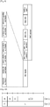
- FIG. 9 shows an example of a MAC PDU.
- a MAC PDU consists of a MAC header, zero or more MAC CEs, zero or more MAC service data units (SDUs), and optionally padding. Both the MAC header and the MAC SDUs are of variable sizes.
- FIG. 10 to FIG. 12 shows an example of a MAC PDU subheader.
- a MAC PDU header consists of one or more MAC PDU subheaders. Each subheader corresponds to either a MAC SDU, a MAC CE or padding.
- a MAC PDU subheader consists of the six header fields R/R/E/LCID/F/L but for the last subheader in the MAC PDU and for fixed sized MAC CEs.
- FIG. 10 shows R/R/E/LCID/F/L MAC PDU subheader with 7-bits L field.
- FIG. 11 shows R/R/E/LCID/F/L MAC PDU subheader with 15-bits L field.
- the last subheader in the MAC PDU and subheaders for fixed sized MAC CEs consist solely of the four header fields R/R/E/LCID.
- a MAC PDU subheader corresponding to padding consists of the four header fields R/R/E/LCID.
- FIG. 12 shows R/ R/E/LCID MAC PDU subheader.
- MAC PDU subheaders have the same order as the corresponding MAC SDUs, MAC CEs and padding.
- MAC CEs are always placed before any MAC SDU. Padding occurs at the end of the MAC PDU, except when single-byte or two-byte padding is required. Padding may have any value and the UE shall ignore it. When padding is performed at the end of the MAC PDU, zero or more padding bytes are allowed. When single-byte or two-byte padding is required, one or two MAC PDU subheaders corresponding to padding are placed at the beginning of the MAC PDU before any other MAC PDU subheader. A maximum of one MAC PDU can be transmitted per transport block (TB) per UE. A maximum of one MCH MAC PDU can be transmitted per TTI.
- TB transport block
- MCH MAC PDU can be transmitted per TTI.
- the UE performing D2D transmission/reception in RRC_IDLE and/or out of network coverage may camp on a cell and then enter RRC_CONNECTED.
- the network may want to configure D2D mode 1 operation for the UE.
- the network may not know whether or not the UE is performing D2D transmission/ reception and even how the UE is performing D2D transmission/D2D reception. That is, the network may not know information on D2D transmission/reception of the UE.
- D2D related information needs to be transmitted to the network upon entering RRC_CONNECTED.
- a method for indicating D2D related information according to an embodiment of the present invention is described.
- FIG. 13 shows an example of a method for transmitting D2D related information according to an embodiment of the present invention.
- the UE indicates at least one of a service type/quality of service (QoS) characteristics of ongoing/initiated D2D operation or a D2D configuration to the network (i.e. eNB or MME) in RRC_CONNECTED (e.g. upon entering RRC_CONNECTED or upon initiation of D2D service for D2D operation).
- QoS quality of service
- the service type of the D2D operation may include voice, video, short message, image, etc.
- the QOS characteristics of the D2D operation may include at least one of delay and bit rate.
- the D2D configuration may be a configuration used for the D2D operation that the UE performed in RRC_IDLE.
- the D2D configuration may include D2D mode and D2D scheduling configuration that the UE used for D2D transmission in RRC_IDLE.
- the D2D scheduling configuration may include interval for D2D transmissions, scheduling period, and timing of scheduling assignment.
- This indication may be included in a NAS message such as tracking area update message, attach request message, or service request message. In this case, this indication may be transmitted to the MME. Then, the MME may transmit this indication to the eNB via a S1 message. Thereafter, the eNB schedules D2D transmissions or D2D receptions in D2D mode 1, based on this indication (e.g. configuring periodic/semi-persistent scheduling for voice service).
- step S110 the UE indicates stop of the D2D operation to the network.
- the stop of the D2D operation may be indicated via a MAC CE, RLC control information, PDCP control information, a RRC message, a NAS message, or an application message.
- the D2D scheduling configuration may further include the D2D TX scheduling configuration (used for the UE to perform D2D transmissions).
- the D2D TX scheduling configuration may include D2D TX D-RNTI (DRNTI) for D2D transmissions, D2D TX scheduling interval, and either D2D TX scheduling validity time or a length of a D2D TX scheduling period.
- D-RNTI may defined for the eNB to allocate D2D scheduling assignment to the UE performing D2D communication.
- the UE may consider that one or more D2D transmissions are periodically scheduled every D2D TX scheduling interval until the D2D TX scheduling validity time expires or the end of a D2D TX scheduling period.
- FIG. 14 shows an example of a D2D scheduling configuration and a D2D scheduling assignment.
- the D2D scheduling configuration configures interval for D2D transmissions, scheduling period (or validity time), and timing of scheduling assignment.
- the D2D scheduling configuration may further include the D2D RX scheduling configuration (used for the UE to perform D2D receptions).
- the D2D RX scheduling configuration may include D2D RX scheduling interval, and either D2D RX scheduling validity time or a length of a D2D RX scheduling period.
- the UE may consider that D2D scheduling receptions are periodically scheduled every D2D RX scheduling until the D2D RX scheduling validity time expires or the end of a D2D RX scheduling period.
- FIG. 15 shows a wireless communication system to implement an example of the present invention.
- An eNB 800 may include a processor 810, a memory 820 and a transceiver 830.
- the processor 810 may be configured to implement proposed functions, procedures and/or methods described in this description. Layers of the radio interface protocol may be implemented in the processor 810.
- the memory 820 is operatively coupled with the processor 810 and stores a variety of information to operate the processor 810.
- the transceiver 830 is operatively coupled with the processor 810, and transmits and/or receives a radio signal.
- a UE 900 may include a processor 910, a memory 920 and a transceiver 930.
- the processor 910 may be configured to implement proposed functions, procedures and/or methods described in this description. Layers of the radio interface protocol may be implemented in the processor 910.
- the memory 920 is operatively coupled with the processor 910 and stores a variety of information to operate the processor 910.
- the transceiver 930 is operatively coupled with the processor 910, and transmits and/or receives a radio signal.
- the processors 810, 910 may include application-specific integrated circuit (ASIC), other chipset, logic circuit and/or data processing device.
- the memories 820, 920 may include read-only memory (ROM), random access memory (RAM), flash memory, memory card, storage medium and/or other storage device.
- the transceivers 830, 930 may include baseband circuitry to process radio frequency signals.
- the techniques described herein can be implemented with modules (e.g., procedures, functions, and so on) that perform the functions described herein.
- the modules can be stored in memories 820, 920 and executed by processors 810, 910.
- the memories 820, 920 can be implemented within the processors 810, 910 or external to the processors 810, 910 in which case those can be communicatively coupled to the processors 810, 910 via various means as is known in the art.
Claims (7)
- Procédé pour un équipement utilisateur, UE, dans un système de communication sans fil, le procédé comprenant :la réalisation, au niveau de l'UE, d'une communication dispositif à dispositif, D2D,dans un mode veille de contrôle de ressources radio, RRC ;l'entrée, au niveau de l'UE, dans un mode connecté RRC ;à l'entrée en mode connecté RRC au niveau de l'UE, la émission, au niveau de l'UE,d'informations relatives au D2D de la communication D2D qui est réalisée dans un mode veille RRC à une entité de gestion de mobilité, MME, via un message de strate de non-accès, NAS, dans lequel les informations relatives au D2D comportent des caractéristiques de qualité de service, QoS, de la communication D2D et une configuration D2D de la communication D2D, dans lequel le message NAS amène la MME à émettre les informations relatives au D2D à un noeud B évolué, eNB ;la réception, au niveau de l'UE, d'informations de programmation pour la communication D2D dans un mode D2D 1 sur la base des informations relatives au D2D, à partir du eNB ; etl'émission, au niveau de l'UE, d'informations informant d'un arrêt de la communication D2D à la MME,dans lequel les caractéristiques QoS de la communication D2D comportent au moins l'un parmi un retard et un débit binaire,dans lequel la configuration D2D comporte le mode D2D 1 et la configuration de programmation D2D de la communication D2D qui est réalisée par l'UE dans le mode veille RRC.
- Procédé selon la revendication 1, dans lequel la configuration D2D est une configuration d'une communication D2D que l'UE réalise dans le mode veille RRC.
- Procédé selon la revendication 1, dans lequel la configuration de programmation D2D comporte au moins l'un parmi un intervalle pour la communication D2D, une période de programmation, ou une synchronisation d'attribution de programmation.
- Procédé selon la revendication 1, comprenant en outre l'émission d'informations sur une configuration de canaux D2D au réseau.
- Procédé selon la revendication 1, comprenant en outre l'émission d'informations indiquant si l'UE réalise ou non une communication D2D avec un autre UE au réseau.
- Procédé selon la revendication 1, comprenant en outre l'émission d'un message de demande de service indiquant la communication D2D à la MME.
- Équipement utilisateur, UE, comprenant un moyen configuré pour réaliser le procédé défini dans la revendication 1.
Applications Claiming Priority (2)
| Application Number | Priority Date | Filing Date | Title |
|---|---|---|---|
| US201461968994P | 2014-03-21 | 2014-03-21 | |
| PCT/KR2015/002787 WO2015142132A1 (fr) | 2014-03-21 | 2015-03-23 | Procédé et appareil d'indication d'informations d2d dans un système de communication sans fil |
Publications (3)
| Publication Number | Publication Date |
|---|---|
| EP3120469A1 EP3120469A1 (fr) | 2017-01-25 |
| EP3120469A4 EP3120469A4 (fr) | 2017-11-22 |
| EP3120469B1 true EP3120469B1 (fr) | 2019-09-04 |
Family
ID=54144991
Family Applications (1)
| Application Number | Title | Priority Date | Filing Date |
|---|---|---|---|
| EP15765005.2A Active EP3120469B1 (fr) | 2014-03-21 | 2015-03-23 | Procédé et appareil d'indication d'informations d2d dans un système de communication sans fil |
Country Status (4)
| Country | Link |
|---|---|
| US (1) | US10091707B2 (fr) |
| EP (1) | EP3120469B1 (fr) |
| CN (1) | CN106105059B (fr) |
| WO (1) | WO2015142132A1 (fr) |
Families Citing this family (21)
| Publication number | Priority date | Publication date | Assignee | Title |
|---|---|---|---|---|
| EP3248426B1 (fr) | 2015-01-23 | 2020-07-22 | LG Electronics Inc. | Procédé pour sélectionner une autorisation de liaison latérale pour un ue d2d dans un système de communication d2d et dispositif correspondant |
| CN107251611B (zh) * | 2015-03-13 | 2020-04-14 | 华为技术有限公司 | 一种业务处理方法、相关装置和系统 |
| WO2017052335A1 (fr) * | 2015-09-25 | 2017-03-30 | 엘지전자 주식회사 | Procédé de réalisation d'une communication directe de dispositif à dispositif dans un système de communication sans fil et dispositif associé |
| WO2017070842A1 (fr) | 2015-10-27 | 2017-05-04 | 华为技术有限公司 | Système, appareil et procédé de communication de dispositif à dispositif (d2d) |
| WO2017083025A1 (fr) * | 2015-11-09 | 2017-05-18 | Intel IP Corporation | Espace de découverte de dispositif à dispositif amélioré |
| EP3412090B1 (fr) | 2016-02-03 | 2019-10-23 | Telefonaktiebolaget LM Ericsson (PUBL) | Programmation périodique efficace pour communications sans fil |
| WO2017171895A1 (fr) * | 2016-04-01 | 2017-10-05 | Intel Corporation | Adaptation de liaison pour communication de dispositif à dispositif (d2d) de faible complexité |
| US20190159174A1 (en) * | 2016-04-08 | 2019-05-23 | Lg Electronics Inc. | Method for setting resource for device-to-device communication in wireless communication system, and apparatus for same |
| CN109076633B (zh) * | 2016-05-18 | 2021-08-31 | 华为技术有限公司 | 传输方法、接入点和站点 |
| KR102207467B1 (ko) * | 2016-05-20 | 2021-01-25 | 후아웨이 테크놀러지 컴퍼니 리미티드 | 패킷 도메인에서 음성 서비스를 스케줄링하는 방법 및 장치 |
| US10660115B1 (en) * | 2016-10-19 | 2020-05-19 | Sprint Spectrum L.P. | Systems and methods for configuring a semi-persistent scheduler |
| WO2018145292A1 (fr) * | 2017-02-10 | 2018-08-16 | 华为技术有限公司 | Procédé, dispositif, et système de communication |
| US20180279275A1 (en) * | 2017-03-23 | 2018-09-27 | Asustek Computer Inc. | Method and apparatus of facilitating reporting assistance information for sidelink service in a wireless communication system |
| FI3603293T3 (fi) * | 2017-03-23 | 2023-04-03 | Apple Inc | Priorisoitu viestinvälitys ja resurssin valinta ajoneuvojen välistä (v2v) sivuyhteysviestintää varten |
| US11672035B2 (en) * | 2018-06-14 | 2023-06-06 | Lg Electronics Inc. | Method and apparatus for performing sidelink communication by UE in NR V2X |
| CN114666849A (zh) * | 2018-08-10 | 2022-06-24 | 大唐移动通信设备有限公司 | 一种直连通信的方法、amf、接入网功能实体及计算机存储介质 |
| CN110972116B (zh) * | 2018-09-28 | 2021-08-20 | 华为技术有限公司 | 一种通信方法、装置、介质、程序产品及系统 |
| EP3709760B1 (fr) * | 2019-03-14 | 2021-09-29 | ASUSTek Computer Inc. | Procédés et appareils pour l'établissement d'un canal logique de liaison latérale dans un système de communication sans fil |
| KR20200114316A (ko) | 2019-03-28 | 2020-10-07 | 삼성전자주식회사 | 무선 통신 시스템에서 직접 통신을 위한 사이드링크 RLC (Radio Link Control) 계층 파라미터를 구성하는 장치 및 방법 |
| EP4274300A3 (fr) * | 2019-04-30 | 2023-12-06 | Guangdong Oppo Mobile Telecommunications Corp., Ltd. | Procédé et dispositif de traitement d'informations, et support d'informations |
| CN112543461B (zh) * | 2019-09-20 | 2023-01-17 | 大唐移动通信设备有限公司 | 接口状态维护方法、装置、设备及计算机可读存储介质 |
Citations (1)
| Publication number | Priority date | Publication date | Assignee | Title |
|---|---|---|---|---|
| US20150156807A1 (en) * | 2012-08-17 | 2015-06-04 | Huawei Technologies Co., Ltd. | Bearer establishment method, base station, packet data gateway, and computer system |
Family Cites Families (7)
| Publication number | Priority date | Publication date | Assignee | Title |
|---|---|---|---|---|
| US9265078B2 (en) * | 2011-05-02 | 2016-02-16 | Lg Electronics Inc. | Method for performing device-to-device communication in wireless access system and apparatus therefor |
| US9288729B2 (en) * | 2011-08-31 | 2016-03-15 | Lg Electronics Inc. | Method for performing a change of mode in devices directly communicating with each other in a wireless connection system, and apparatus for same |
| CN103096503B (zh) * | 2011-11-04 | 2016-03-30 | 华为技术有限公司 | 通信匹配方法、用户设备和基站 |
| JP2015521009A (ja) * | 2012-05-23 | 2015-07-23 | 京セラ株式会社 | セルラ通信システムにおける第1のd2d装置から第2のd2d装置への装置間(d2d)制御データの送信 |
| US10045386B2 (en) * | 2012-05-31 | 2018-08-07 | Interdigital Patent Holdings, Inc. | Method and apparatus for device-to-device (D2D) mobility in wireless systems |
| TWI620459B (zh) | 2012-05-31 | 2018-04-01 | 內數位專利控股公司 | 在蜂巢式通訊系統中賦能直鏈通訊排程及控制方法 |
| ES2734476T3 (es) * | 2012-07-20 | 2019-12-10 | Lg Electronics Inc | Método y aparato para transmitir un mensaje relacionado con una conexión dispositivo a dispositivo en un sistema de comunicación inalámbrica |
-
2015
- 2015-03-23 CN CN201580014715.5A patent/CN106105059B/zh active Active
- 2015-03-23 WO PCT/KR2015/002787 patent/WO2015142132A1/fr active Application Filing
- 2015-03-23 EP EP15765005.2A patent/EP3120469B1/fr active Active
- 2015-03-23 US US15/116,151 patent/US10091707B2/en active Active
Patent Citations (1)
| Publication number | Priority date | Publication date | Assignee | Title |
|---|---|---|---|---|
| US20150156807A1 (en) * | 2012-08-17 | 2015-06-04 | Huawei Technologies Co., Ltd. | Bearer establishment method, base station, packet data gateway, and computer system |
Also Published As
| Publication number | Publication date |
|---|---|
| EP3120469A4 (fr) | 2017-11-22 |
| WO2015142132A1 (fr) | 2015-09-24 |
| CN106105059A (zh) | 2016-11-09 |
| US10091707B2 (en) | 2018-10-02 |
| US20170181064A1 (en) | 2017-06-22 |
| CN106105059B (zh) | 2019-05-03 |
| EP3120469A1 (fr) | 2017-01-25 |
Similar Documents
| Publication | Publication Date | Title |
|---|---|---|
| EP3120469B1 (fr) | Procédé et appareil d'indication d'informations d2d dans un système de communication sans fil | |
| US11096083B2 (en) | Method and apparatus for performing buffer status reporting procedure for relaying in wireless communication system | |
| EP3141068B1 (fr) | Procédé et appareil de configuration d'une transmission d'informations de commande d2d dans un système de communication sans fil | |
| EP3120609B1 (fr) | Procédé et appareil permettant d'annuler un rapport d'état de tampon déclenché pour la transmission dispositif-dispositif dans un système de communication sans fil | |
| US10512062B2 (en) | Method and apparatus for indicating D2D resource pool in wireless communication system | |
| EP3123799B1 (fr) | Procédé et appareil pour classer par ordre de priorité une transmission de dispositif à dispositif (d2d) et une réception d2d dans un système de communication sans fil | |
| EP3105957B1 (fr) | Procédé et appareil d'indication de qos de données de d2d dans un système de communication sans fil | |
| US10154537B2 (en) | Method and apparatus for canceling triggered prose BSR in wireless communication system | |
| EP3120607B1 (fr) | Procédé et appareil pour configurer un rapport d'état de tampon pour une transmission de sureté publique dans un système de communication sans fil | |
| EP3053403B1 (fr) | Procédé et appareil destinés à la transmission d'informations relatives à la communication dispositif à dispositif dans un système de communication sans fil | |
| EP3053383B1 (fr) | Procédé et appareil de transmission d'indication d'opération d2d dans un système de communications sans fil | |
| EP3461156B1 (fr) | D2d gap pour le signal de découverte d2d | |
| US10080128B2 (en) | Method and apparatus for configuring D2D discovery specific logical channel group in wireless communication system | |
| US10111231B2 (en) | Method and apparatus for performing D2D operation in wireless communication system | |
| US20170086238A1 (en) | As-nas interaction method for d2d communication and apparatus for the same in wireless communication system | |
| US10142880B2 (en) | Method and apparatus for configuring scheduling request prohibit timer for prose priority in wireless communication system | |
| US10687381B2 (en) | Method and apparatus for configuring prohibit timer for prose transmission in wireless communication system | |
| US10231252B2 (en) | Method and apparatus for prioritizing device-to-device reception over MBMS reception in wireless communication system | |
| EP3123782B1 (fr) | Procédé et appareil pour réaliser un contrôle d'accès spécifique de dispositif à dispositif (d2d) dans un système de communication sans fil |
Legal Events
| Date | Code | Title | Description |
|---|---|---|---|
| STAA | Information on the status of an ep patent application or granted ep patent |
Free format text: STATUS: THE INTERNATIONAL PUBLICATION HAS BEEN MADE |
|
| PUAI | Public reference made under article 153(3) epc to a published international application that has entered the european phase |
Free format text: ORIGINAL CODE: 0009012 |
|
| STAA | Information on the status of an ep patent application or granted ep patent |
Free format text: STATUS: REQUEST FOR EXAMINATION WAS MADE |
|
| 17P | Request for examination filed |
Effective date: 20161003 |
|
| AK | Designated contracting states |
Kind code of ref document: A1 Designated state(s): AL AT BE BG CH CY CZ DE DK EE ES FI FR GB GR HR HU IE IS IT LI LT LU LV MC MK MT NL NO PL PT RO RS SE SI SK SM TR |
|
| AX | Request for extension of the european patent |
Extension state: BA ME |
|
| DAV | Request for validation of the european patent (deleted) | ||
| DAX | Request for extension of the european patent (deleted) | ||
| A4 | Supplementary search report drawn up and despatched |
Effective date: 20171023 |
|
| RIC1 | Information provided on ipc code assigned before grant |
Ipc: H04W 48/02 20090101ALN20171017BHEP Ipc: H04W 4/00 20090101ALI20171017BHEP Ipc: H04B 7/26 20060101AFI20171017BHEP |
|
| STAA | Information on the status of an ep patent application or granted ep patent |
Free format text: STATUS: EXAMINATION IS IN PROGRESS |
|
| 17Q | First examination report despatched |
Effective date: 20180831 |
|
| REG | Reference to a national code |
Ref country code: DE Ref legal event code: R079 Ref document number: 602015037238 Country of ref document: DE Free format text: PREVIOUS MAIN CLASS: H04B0007260000 Ipc: H04W0072020000 |
|
| GRAP | Despatch of communication of intention to grant a patent |
Free format text: ORIGINAL CODE: EPIDOSNIGR1 |
|
| STAA | Information on the status of an ep patent application or granted ep patent |
Free format text: STATUS: GRANT OF PATENT IS INTENDED |
|
| RIC1 | Information provided on ipc code assigned before grant |
Ipc: H04W 48/02 20090101ALN20190205BHEP Ipc: H04B 7/26 20060101AFI20190205BHEP Ipc: H04W 76/14 20180101ALI20190205BHEP |
|
| RIC1 | Information provided on ipc code assigned before grant |
Ipc: H04B 7/26 20060101ALI20190211BHEP Ipc: H04W 72/02 20090101AFI20190211BHEP Ipc: H04W 76/14 20180101ALI20190211BHEP Ipc: H04W 8/00 20090101ALN20190211BHEP Ipc: H04W 48/02 20090101ALN20190211BHEP |
|
| RIC1 | Information provided on ipc code assigned before grant |
Ipc: H04W 8/00 20090101ALN20190215BHEP Ipc: H04W 48/02 20090101ALN20190215BHEP Ipc: H04W 76/14 20180101ALI20190215BHEP Ipc: H04B 7/26 20060101ALI20190215BHEP Ipc: H04W 72/02 20090101AFI20190215BHEP |
|
| INTG | Intention to grant announced |
Effective date: 20190313 |
|
| GRAS | Grant fee paid |
Free format text: ORIGINAL CODE: EPIDOSNIGR3 |
|
| GRAA | (expected) grant |
Free format text: ORIGINAL CODE: 0009210 |
|
| STAA | Information on the status of an ep patent application or granted ep patent |
Free format text: STATUS: THE PATENT HAS BEEN GRANTED |
|
| AK | Designated contracting states |
Kind code of ref document: B1 Designated state(s): AL AT BE BG CH CY CZ DE DK EE ES FI FR GB GR HR HU IE IS IT LI LT LU LV MC MK MT NL NO PL PT RO RS SE SI SK SM TR |
|
| REG | Reference to a national code |
Ref country code: GB Ref legal event code: FG4D |
|
| REG | Reference to a national code |
Ref country code: CH Ref legal event code: EP |
|
| REG | Reference to a national code |
Ref country code: AT Ref legal event code: REF Ref document number: 1177199 Country of ref document: AT Kind code of ref document: T Effective date: 20190915 |
|
| REG | Reference to a national code |
Ref country code: DE Ref legal event code: R096 Ref document number: 602015037238 Country of ref document: DE |
|
| REG | Reference to a national code |
Ref country code: IE Ref legal event code: FG4D |
|
| REG | Reference to a national code |
Ref country code: NL Ref legal event code: MP Effective date: 20190904 |
|
| REG | Reference to a national code |
Ref country code: LT Ref legal event code: MG4D |
|
| PG25 | Lapsed in a contracting state [announced via postgrant information from national office to epo] |
Ref country code: LT Free format text: LAPSE BECAUSE OF FAILURE TO SUBMIT A TRANSLATION OF THE DESCRIPTION OR TO PAY THE FEE WITHIN THE PRESCRIBED TIME-LIMIT Effective date: 20190904 Ref country code: SE Free format text: LAPSE BECAUSE OF FAILURE TO SUBMIT A TRANSLATION OF THE DESCRIPTION OR TO PAY THE FEE WITHIN THE PRESCRIBED TIME-LIMIT Effective date: 20190904 Ref country code: BG Free format text: LAPSE BECAUSE OF FAILURE TO SUBMIT A TRANSLATION OF THE DESCRIPTION OR TO PAY THE FEE WITHIN THE PRESCRIBED TIME-LIMIT Effective date: 20191204 Ref country code: FI Free format text: LAPSE BECAUSE OF FAILURE TO SUBMIT A TRANSLATION OF THE DESCRIPTION OR TO PAY THE FEE WITHIN THE PRESCRIBED TIME-LIMIT Effective date: 20190904 Ref country code: NO Free format text: LAPSE BECAUSE OF FAILURE TO SUBMIT A TRANSLATION OF THE DESCRIPTION OR TO PAY THE FEE WITHIN THE PRESCRIBED TIME-LIMIT Effective date: 20191204 Ref country code: HR Free format text: LAPSE BECAUSE OF FAILURE TO SUBMIT A TRANSLATION OF THE DESCRIPTION OR TO PAY THE FEE WITHIN THE PRESCRIBED TIME-LIMIT Effective date: 20190904 |
|
| PG25 | Lapsed in a contracting state [announced via postgrant information from national office to epo] |
Ref country code: LV Free format text: LAPSE BECAUSE OF FAILURE TO SUBMIT A TRANSLATION OF THE DESCRIPTION OR TO PAY THE FEE WITHIN THE PRESCRIBED TIME-LIMIT Effective date: 20190904 Ref country code: AL Free format text: LAPSE BECAUSE OF FAILURE TO SUBMIT A TRANSLATION OF THE DESCRIPTION OR TO PAY THE FEE WITHIN THE PRESCRIBED TIME-LIMIT Effective date: 20190904 Ref country code: RS Free format text: LAPSE BECAUSE OF FAILURE TO SUBMIT A TRANSLATION OF THE DESCRIPTION OR TO PAY THE FEE WITHIN THE PRESCRIBED TIME-LIMIT Effective date: 20190904 Ref country code: GR Free format text: LAPSE BECAUSE OF FAILURE TO SUBMIT A TRANSLATION OF THE DESCRIPTION OR TO PAY THE FEE WITHIN THE PRESCRIBED TIME-LIMIT Effective date: 20191205 Ref country code: ES Free format text: LAPSE BECAUSE OF FAILURE TO SUBMIT A TRANSLATION OF THE DESCRIPTION OR TO PAY THE FEE WITHIN THE PRESCRIBED TIME-LIMIT Effective date: 20190904 |
|
| REG | Reference to a national code |
Ref country code: AT Ref legal event code: MK05 Ref document number: 1177199 Country of ref document: AT Kind code of ref document: T Effective date: 20190904 |
|
| PG25 | Lapsed in a contracting state [announced via postgrant information from national office to epo] |
Ref country code: AT Free format text: LAPSE BECAUSE OF FAILURE TO SUBMIT A TRANSLATION OF THE DESCRIPTION OR TO PAY THE FEE WITHIN THE PRESCRIBED TIME-LIMIT Effective date: 20190904 Ref country code: PT Free format text: LAPSE BECAUSE OF FAILURE TO SUBMIT A TRANSLATION OF THE DESCRIPTION OR TO PAY THE FEE WITHIN THE PRESCRIBED TIME-LIMIT Effective date: 20200106 Ref country code: PL Free format text: LAPSE BECAUSE OF FAILURE TO SUBMIT A TRANSLATION OF THE DESCRIPTION OR TO PAY THE FEE WITHIN THE PRESCRIBED TIME-LIMIT Effective date: 20190904 Ref country code: IT Free format text: LAPSE BECAUSE OF FAILURE TO SUBMIT A TRANSLATION OF THE DESCRIPTION OR TO PAY THE FEE WITHIN THE PRESCRIBED TIME-LIMIT Effective date: 20190904 Ref country code: EE Free format text: LAPSE BECAUSE OF FAILURE TO SUBMIT A TRANSLATION OF THE DESCRIPTION OR TO PAY THE FEE WITHIN THE PRESCRIBED TIME-LIMIT Effective date: 20190904 Ref country code: RO Free format text: LAPSE BECAUSE OF FAILURE TO SUBMIT A TRANSLATION OF THE DESCRIPTION OR TO PAY THE FEE WITHIN THE PRESCRIBED TIME-LIMIT Effective date: 20190904 Ref country code: NL Free format text: LAPSE BECAUSE OF FAILURE TO SUBMIT A TRANSLATION OF THE DESCRIPTION OR TO PAY THE FEE WITHIN THE PRESCRIBED TIME-LIMIT Effective date: 20190904 |
|
| PG25 | Lapsed in a contracting state [announced via postgrant information from national office to epo] |
Ref country code: SM Free format text: LAPSE BECAUSE OF FAILURE TO SUBMIT A TRANSLATION OF THE DESCRIPTION OR TO PAY THE FEE WITHIN THE PRESCRIBED TIME-LIMIT Effective date: 20190904 Ref country code: CZ Free format text: LAPSE BECAUSE OF FAILURE TO SUBMIT A TRANSLATION OF THE DESCRIPTION OR TO PAY THE FEE WITHIN THE PRESCRIBED TIME-LIMIT Effective date: 20190904 Ref country code: SK Free format text: LAPSE BECAUSE OF FAILURE TO SUBMIT A TRANSLATION OF THE DESCRIPTION OR TO PAY THE FEE WITHIN THE PRESCRIBED TIME-LIMIT Effective date: 20190904 Ref country code: IS Free format text: LAPSE BECAUSE OF FAILURE TO SUBMIT A TRANSLATION OF THE DESCRIPTION OR TO PAY THE FEE WITHIN THE PRESCRIBED TIME-LIMIT Effective date: 20200224 |
|
| REG | Reference to a national code |
Ref country code: DE Ref legal event code: R097 Ref document number: 602015037238 Country of ref document: DE |
|
| PLBE | No opposition filed within time limit |
Free format text: ORIGINAL CODE: 0009261 |
|
| STAA | Information on the status of an ep patent application or granted ep patent |
Free format text: STATUS: NO OPPOSITION FILED WITHIN TIME LIMIT |
|
| PG2D | Information on lapse in contracting state deleted |
Ref country code: IS |
|
| PG25 | Lapsed in a contracting state [announced via postgrant information from national office to epo] |
Ref country code: DK Free format text: LAPSE BECAUSE OF FAILURE TO SUBMIT A TRANSLATION OF THE DESCRIPTION OR TO PAY THE FEE WITHIN THE PRESCRIBED TIME-LIMIT Effective date: 20190904 Ref country code: IS Free format text: LAPSE BECAUSE OF FAILURE TO SUBMIT A TRANSLATION OF THE DESCRIPTION OR TO PAY THE FEE WITHIN THE PRESCRIBED TIME-LIMIT Effective date: 20200105 |
|
| 26N | No opposition filed |
Effective date: 20200605 |
|
| PG25 | Lapsed in a contracting state [announced via postgrant information from national office to epo] |
Ref country code: SI Free format text: LAPSE BECAUSE OF FAILURE TO SUBMIT A TRANSLATION OF THE DESCRIPTION OR TO PAY THE FEE WITHIN THE PRESCRIBED TIME-LIMIT Effective date: 20190904 |
|
| PG25 | Lapsed in a contracting state [announced via postgrant information from national office to epo] |
Ref country code: MC Free format text: LAPSE BECAUSE OF FAILURE TO SUBMIT A TRANSLATION OF THE DESCRIPTION OR TO PAY THE FEE WITHIN THE PRESCRIBED TIME-LIMIT Effective date: 20190904 |
|
| REG | Reference to a national code |
Ref country code: CH Ref legal event code: PL |
|
| REG | Reference to a national code |
Ref country code: BE Ref legal event code: MM Effective date: 20200331 |
|
| PG25 | Lapsed in a contracting state [announced via postgrant information from national office to epo] |
Ref country code: LU Free format text: LAPSE BECAUSE OF NON-PAYMENT OF DUE FEES Effective date: 20200323 |
|
| PG25 | Lapsed in a contracting state [announced via postgrant information from national office to epo] |
Ref country code: IE Free format text: LAPSE BECAUSE OF NON-PAYMENT OF DUE FEES Effective date: 20200323 Ref country code: FR Free format text: LAPSE BECAUSE OF NON-PAYMENT OF DUE FEES Effective date: 20200331 Ref country code: LI Free format text: LAPSE BECAUSE OF NON-PAYMENT OF DUE FEES Effective date: 20200331 Ref country code: CH Free format text: LAPSE BECAUSE OF NON-PAYMENT OF DUE FEES Effective date: 20200331 |
|
| PG25 | Lapsed in a contracting state [announced via postgrant information from national office to epo] |
Ref country code: BE Free format text: LAPSE BECAUSE OF NON-PAYMENT OF DUE FEES Effective date: 20200331 |
|
| GBPC | Gb: european patent ceased through non-payment of renewal fee |
Effective date: 20200323 |
|
| PG25 | Lapsed in a contracting state [announced via postgrant information from national office to epo] |
Ref country code: GB Free format text: LAPSE BECAUSE OF NON-PAYMENT OF DUE FEES Effective date: 20200323 |
|
| PG25 | Lapsed in a contracting state [announced via postgrant information from national office to epo] |
Ref country code: TR Free format text: LAPSE BECAUSE OF FAILURE TO SUBMIT A TRANSLATION OF THE DESCRIPTION OR TO PAY THE FEE WITHIN THE PRESCRIBED TIME-LIMIT Effective date: 20190904 Ref country code: MT Free format text: LAPSE BECAUSE OF FAILURE TO SUBMIT A TRANSLATION OF THE DESCRIPTION OR TO PAY THE FEE WITHIN THE PRESCRIBED TIME-LIMIT Effective date: 20190904 Ref country code: CY Free format text: LAPSE BECAUSE OF FAILURE TO SUBMIT A TRANSLATION OF THE DESCRIPTION OR TO PAY THE FEE WITHIN THE PRESCRIBED TIME-LIMIT Effective date: 20190904 |
|
| PG25 | Lapsed in a contracting state [announced via postgrant information from national office to epo] |
Ref country code: MK Free format text: LAPSE BECAUSE OF FAILURE TO SUBMIT A TRANSLATION OF THE DESCRIPTION OR TO PAY THE FEE WITHIN THE PRESCRIBED TIME-LIMIT Effective date: 20190904 |
|
| PGFP | Annual fee paid to national office [announced via postgrant information from national office to epo] |
Ref country code: DE Payment date: 20230206 Year of fee payment: 9 |