EP3746323B1 - Kraftfahrzeug mit nachgerüstetem elektrischen antrieb - Google Patents
Kraftfahrzeug mit nachgerüstetem elektrischen antrieb Download PDFInfo
- Publication number
- EP3746323B1 EP3746323B1 EP19705111.3A EP19705111A EP3746323B1 EP 3746323 B1 EP3746323 B1 EP 3746323B1 EP 19705111 A EP19705111 A EP 19705111A EP 3746323 B1 EP3746323 B1 EP 3746323B1
- Authority
- EP
- European Patent Office
- Prior art keywords
- electric motor
- transmission
- gear
- motor
- gearbox
- Prior art date
- Legal status (The legal status is an assumption and is not a legal conclusion. Google has not performed a legal analysis and makes no representation as to the accuracy of the status listed.)
- Active
Links
Images


Classifications
-
- B—PERFORMING OPERATIONS; TRANSPORTING
- B60—VEHICLES IN GENERAL
- B60K—ARRANGEMENT OR MOUNTING OF PROPULSION UNITS OR OF TRANSMISSIONS IN VEHICLES; ARRANGEMENT OR MOUNTING OF PLURAL DIVERSE PRIME-MOVERS IN VEHICLES; AUXILIARY DRIVES FOR VEHICLES; INSTRUMENTATION OR DASHBOARDS FOR VEHICLES; ARRANGEMENTS IN CONNECTION WITH COOLING, AIR INTAKE, GAS EXHAUST OR FUEL SUPPLY OF PROPULSION UNITS IN VEHICLES
- B60K6/00—Arrangement or mounting of plural diverse prime-movers for mutual or common propulsion, e.g. hybrid propulsion systems comprising electric motors and internal combustion engines
- B60K6/20—Arrangement or mounting of plural diverse prime-movers for mutual or common propulsion, e.g. hybrid propulsion systems comprising electric motors and internal combustion engines the prime-movers consisting of electric motors and internal combustion engines, e.g. HEVs
- B60K6/42—Arrangement or mounting of plural diverse prime-movers for mutual or common propulsion, e.g. hybrid propulsion systems comprising electric motors and internal combustion engines the prime-movers consisting of electric motors and internal combustion engines, e.g. HEVs characterised by the architecture of the hybrid electric vehicle
- B60K6/48—Parallel type
-
- B—PERFORMING OPERATIONS; TRANSPORTING
- B60—VEHICLES IN GENERAL
- B60K—ARRANGEMENT OR MOUNTING OF PROPULSION UNITS OR OF TRANSMISSIONS IN VEHICLES; ARRANGEMENT OR MOUNTING OF PLURAL DIVERSE PRIME-MOVERS IN VEHICLES; AUXILIARY DRIVES FOR VEHICLES; INSTRUMENTATION OR DASHBOARDS FOR VEHICLES; ARRANGEMENTS IN CONNECTION WITH COOLING, AIR INTAKE, GAS EXHAUST OR FUEL SUPPLY OF PROPULSION UNITS IN VEHICLES
- B60K6/00—Arrangement or mounting of plural diverse prime-movers for mutual or common propulsion, e.g. hybrid propulsion systems comprising electric motors and internal combustion engines
- B60K6/20—Arrangement or mounting of plural diverse prime-movers for mutual or common propulsion, e.g. hybrid propulsion systems comprising electric motors and internal combustion engines the prime-movers consisting of electric motors and internal combustion engines, e.g. HEVs
- B60K6/22—Arrangement or mounting of plural diverse prime-movers for mutual or common propulsion, e.g. hybrid propulsion systems comprising electric motors and internal combustion engines the prime-movers consisting of electric motors and internal combustion engines, e.g. HEVs characterised by apparatus, components or means specially adapted for HEVs
- B60K6/40—Arrangement or mounting of plural diverse prime-movers for mutual or common propulsion, e.g. hybrid propulsion systems comprising electric motors and internal combustion engines the prime-movers consisting of electric motors and internal combustion engines, e.g. HEVs characterised by apparatus, components or means specially adapted for HEVs characterised by the assembly or relative disposition of components
- B60K6/405—Housings
-
- B—PERFORMING OPERATIONS; TRANSPORTING
- B60—VEHICLES IN GENERAL
- B60K—ARRANGEMENT OR MOUNTING OF PROPULSION UNITS OR OF TRANSMISSIONS IN VEHICLES; ARRANGEMENT OR MOUNTING OF PLURAL DIVERSE PRIME-MOVERS IN VEHICLES; AUXILIARY DRIVES FOR VEHICLES; INSTRUMENTATION OR DASHBOARDS FOR VEHICLES; ARRANGEMENTS IN CONNECTION WITH COOLING, AIR INTAKE, GAS EXHAUST OR FUEL SUPPLY OF PROPULSION UNITS IN VEHICLES
- B60K6/00—Arrangement or mounting of plural diverse prime-movers for mutual or common propulsion, e.g. hybrid propulsion systems comprising electric motors and internal combustion engines
- B60K6/20—Arrangement or mounting of plural diverse prime-movers for mutual or common propulsion, e.g. hybrid propulsion systems comprising electric motors and internal combustion engines the prime-movers consisting of electric motors and internal combustion engines, e.g. HEVs
- B60K6/50—Architecture of the driveline characterised by arrangement or kind of transmission units
- B60K6/54—Transmission for changing ratio
- B60K6/547—Transmission for changing ratio the transmission being a stepped gearing
-
- B—PERFORMING OPERATIONS; TRANSPORTING
- B60—VEHICLES IN GENERAL
- B60W—CONJOINT CONTROL OF VEHICLE SUB-UNITS OF DIFFERENT TYPE OR DIFFERENT FUNCTION; CONTROL SYSTEMS SPECIALLY ADAPTED FOR HYBRID VEHICLES; ROAD VEHICLE DRIVE CONTROL SYSTEMS FOR PURPOSES NOT RELATED TO THE CONTROL OF A PARTICULAR SUB-UNIT
- B60W10/00—Conjoint control of vehicle sub-units of different type or different function
- B60W10/04—Conjoint control of vehicle sub-units of different type or different function including control of propulsion units
- B60W10/08—Conjoint control of vehicle sub-units of different type or different function including control of propulsion units including control of electric propulsion units, e.g. motors or generators
-
- B—PERFORMING OPERATIONS; TRANSPORTING
- B60—VEHICLES IN GENERAL
- B60W—CONJOINT CONTROL OF VEHICLE SUB-UNITS OF DIFFERENT TYPE OR DIFFERENT FUNCTION; CONTROL SYSTEMS SPECIALLY ADAPTED FOR HYBRID VEHICLES; ROAD VEHICLE DRIVE CONTROL SYSTEMS FOR PURPOSES NOT RELATED TO THE CONTROL OF A PARTICULAR SUB-UNIT
- B60W10/00—Conjoint control of vehicle sub-units of different type or different function
- B60W10/10—Conjoint control of vehicle sub-units of different type or different function including control of change-speed gearings
- B60W10/11—Stepped gearings
- B60W10/111—Stepped gearings with separate change-speed gear trains arranged in series
-
- B—PERFORMING OPERATIONS; TRANSPORTING
- B60—VEHICLES IN GENERAL
- B60W—CONJOINT CONTROL OF VEHICLE SUB-UNITS OF DIFFERENT TYPE OR DIFFERENT FUNCTION; CONTROL SYSTEMS SPECIALLY ADAPTED FOR HYBRID VEHICLES; ROAD VEHICLE DRIVE CONTROL SYSTEMS FOR PURPOSES NOT RELATED TO THE CONTROL OF A PARTICULAR SUB-UNIT
- B60W20/00—Control systems specially adapted for hybrid vehicles
- B60W20/10—Controlling the power contribution of each of the prime movers to meet required power demand
- B60W20/15—Control strategies specially adapted for achieving a particular effect
-
- B—PERFORMING OPERATIONS; TRANSPORTING
- B60—VEHICLES IN GENERAL
- B60W—CONJOINT CONTROL OF VEHICLE SUB-UNITS OF DIFFERENT TYPE OR DIFFERENT FUNCTION; CONTROL SYSTEMS SPECIALLY ADAPTED FOR HYBRID VEHICLES; ROAD VEHICLE DRIVE CONTROL SYSTEMS FOR PURPOSES NOT RELATED TO THE CONTROL OF A PARTICULAR SUB-UNIT
- B60W20/00—Control systems specially adapted for hybrid vehicles
- B60W20/30—Control strategies involving selection of transmission gear ratio
-
- B—PERFORMING OPERATIONS; TRANSPORTING
- B60—VEHICLES IN GENERAL
- B60W—CONJOINT CONTROL OF VEHICLE SUB-UNITS OF DIFFERENT TYPE OR DIFFERENT FUNCTION; CONTROL SYSTEMS SPECIALLY ADAPTED FOR HYBRID VEHICLES; ROAD VEHICLE DRIVE CONTROL SYSTEMS FOR PURPOSES NOT RELATED TO THE CONTROL OF A PARTICULAR SUB-UNIT
- B60W30/00—Purposes of road vehicle drive control systems not related to the control of a particular sub-unit, e.g. of systems using conjoint control of vehicle sub-units
- B60W30/18—Propelling the vehicle
- B60W30/19—Improvement of gear change, e.g. by synchronisation or smoothing gear shift
-
- B—PERFORMING OPERATIONS; TRANSPORTING
- B60—VEHICLES IN GENERAL
- B60K—ARRANGEMENT OR MOUNTING OF PROPULSION UNITS OR OF TRANSMISSIONS IN VEHICLES; ARRANGEMENT OR MOUNTING OF PLURAL DIVERSE PRIME-MOVERS IN VEHICLES; AUXILIARY DRIVES FOR VEHICLES; INSTRUMENTATION OR DASHBOARDS FOR VEHICLES; ARRANGEMENTS IN CONNECTION WITH COOLING, AIR INTAKE, GAS EXHAUST OR FUEL SUPPLY OF PROPULSION UNITS IN VEHICLES
- B60K6/00—Arrangement or mounting of plural diverse prime-movers for mutual or common propulsion, e.g. hybrid propulsion systems comprising electric motors and internal combustion engines
- B60K6/20—Arrangement or mounting of plural diverse prime-movers for mutual or common propulsion, e.g. hybrid propulsion systems comprising electric motors and internal combustion engines the prime-movers consisting of electric motors and internal combustion engines, e.g. HEVs
- B60K6/42—Arrangement or mounting of plural diverse prime-movers for mutual or common propulsion, e.g. hybrid propulsion systems comprising electric motors and internal combustion engines the prime-movers consisting of electric motors and internal combustion engines, e.g. HEVs characterised by the architecture of the hybrid electric vehicle
- B60K6/48—Parallel type
- B60K2006/4808—Electric machine connected or connectable to gearbox output shaft
-
- B—PERFORMING OPERATIONS; TRANSPORTING
- B60—VEHICLES IN GENERAL
- B60K—ARRANGEMENT OR MOUNTING OF PROPULSION UNITS OR OF TRANSMISSIONS IN VEHICLES; ARRANGEMENT OR MOUNTING OF PLURAL DIVERSE PRIME-MOVERS IN VEHICLES; AUXILIARY DRIVES FOR VEHICLES; INSTRUMENTATION OR DASHBOARDS FOR VEHICLES; ARRANGEMENTS IN CONNECTION WITH COOLING, AIR INTAKE, GAS EXHAUST OR FUEL SUPPLY OF PROPULSION UNITS IN VEHICLES
- B60K6/00—Arrangement or mounting of plural diverse prime-movers for mutual or common propulsion, e.g. hybrid propulsion systems comprising electric motors and internal combustion engines
- B60K6/20—Arrangement or mounting of plural diverse prime-movers for mutual or common propulsion, e.g. hybrid propulsion systems comprising electric motors and internal combustion engines the prime-movers consisting of electric motors and internal combustion engines, e.g. HEVs
- B60K6/42—Arrangement or mounting of plural diverse prime-movers for mutual or common propulsion, e.g. hybrid propulsion systems comprising electric motors and internal combustion engines the prime-movers consisting of electric motors and internal combustion engines, e.g. HEVs characterised by the architecture of the hybrid electric vehicle
- B60K6/48—Parallel type
- B60K2006/4816—Electric machine connected or connectable to gearbox internal shaft
-
- Y—GENERAL TAGGING OF NEW TECHNOLOGICAL DEVELOPMENTS; GENERAL TAGGING OF CROSS-SECTIONAL TECHNOLOGIES SPANNING OVER SEVERAL SECTIONS OF THE IPC; TECHNICAL SUBJECTS COVERED BY FORMER USPC CROSS-REFERENCE ART COLLECTIONS [XRACs] AND DIGESTS
- Y02—TECHNOLOGIES OR APPLICATIONS FOR MITIGATION OR ADAPTATION AGAINST CLIMATE CHANGE
- Y02T—CLIMATE CHANGE MITIGATION TECHNOLOGIES RELATED TO TRANSPORTATION
- Y02T10/00—Road transport of goods or passengers
- Y02T10/60—Other road transportation technologies with climate change mitigation effect
- Y02T10/62—Hybrid vehicles
Definitions
- the invention relates to a motor vehicle with an internal combustion engine.
- An existing motor vehicle with an internal combustion engine means a motor vehicle that is powered, i.e. driven, by an internal combustion engine and does not include an electric motor for an electric drive.
- An existing vehicle does regularly include electric motors, for example for starting the internal combustion engine (starter) or for windshield wipers. However, such electric motors do not enable the motor vehicle to be driven, i.e. powered. Such an electric motor is therefore not an electric motor for an electric drive within the meaning of the present invention.
- a mixture of fuel and air is burned, for example, in cylinders in order to move pistons that are movably mounted in the cylinder.
- the ignitable mixture is then formed by an intake and compression stroke in the cylinders.
- Such an internal combustion engine comprises a crankshaft that is coupled to the pistons by means of connecting rods in such a way that the movements of the pistons rotate the crankshaft. Conversely, a rotary movement of the crankshaft can drive the pistons, i.e. move them back and forth.
- Such an internal combustion engine does not rotate evenly because it goes through idle cycles and dead points.
- a flywheel is therefore attached to the crankshaft of such an internal combustion engine. Due to its inertia, a rotating flywheel continues to rotate even when the internal combustion engine goes through idle cycles and dead points. The flywheel therefore compensates for fluctuations in the internal combustion engine's speed.
- crankshaft of an internal combustion engine must rotate so that the pistons of the individual cylinders can complete the intake and compression strokes.
- the rotational movement required for this is generated by an electric starter motor, also known as a starter.
- a starter is usually located near the flywheel.
- the starter shaft is coupled to the flywheel by a clutch, which is subsequently called a starter-flywheel clutch.
- a common starter-flywheel clutch includes a magnetic switch that drives a pinion for engagement. from a starting position into a position that is meshed with the flywheel.
- the electric motor of the starter is activated, which then rotates the crankshaft via the pinion. This moves the pistons. Ignitable mixtures are thereby generated in the cylinders and ignited.
- the pinion is moved back to its starting position, for example with the help of a pre-tensioned spring of the starter-flywheel clutch.
- the starter-flywheel clutch engages and disengages in such a way that torque is only transferred from the electric motor to the flywheel for starting the combustion engine.
- the flywheel is located inside a housing that also houses the gearbox.
- the starter is often attached to this gearbox housing.
- the starter can also be attached to the housing in which the engine is located.
- crankshaft - gearbox clutch An internal combustion engine or its crankshaft is coupled to a gearbox by means of a clutch, which is referred to below as a crankshaft - gearbox clutch, in order to convert the speed of the crankshaft and thus the speed of the internal combustion engine into a drive speed suitable for driving the motor vehicle.
- the crankshaft - gearbox clutch can interrupt the transmission of a rotary motion from the crankshaft to the gearbox.
- the crankshaft is then not coupled to a gearbox, i.e. disengaged, and the gearbox is independent of the internal combustion engine. A rotary motion of the crankshaft is then not transmitted to a shaft of the gearbox.
- Older vehicles with combustion engines in particular cause high levels of pollutant emissions during operation. Vehicles with combustion engines are generally no longer allowed to be driven in large cities if their pollutant emissions exceed specified limits.
- WO 2007/023001 A1 discloses the replacement of an alternator with an electric drive in order to retrofit an existing motor vehicle with a combustion engine with an electric drive. It is also known from this publication that a starter motor can then be omitted.
- the publication EN 10 2012 214 457 A1 discloses a drive system for a motor vehicle with an internal combustion engine, a transmission for the internal combustion engine and an electric machine.
- a method for retrofitting is known from the publication WO 2012/137151 A1 known.
- an existing vehicle with a combustion engine is to be retrofitted with an electric motor
- various requirements must be taken into account.
- An electric motor should not increase the required installation space if possible, as there is generally hardly any free installation space available in existing vehicles.
- very old vehicles which are also called vintage cars once they exceed a certain age limit of 30 years, for example, the original condition should be changed as little as possible.
- a retrofitted vehicle should be able to run purely electrically so that it can also be driven in inner cities without any problems.
- the object of the invention is to retrofit a motor vehicle with an internal combustion engine which meets one or more of the aforementioned requirements. It should preferably also be possible to restore the original condition with little effort.
- the object of the invention is solved by a motor vehicle having the features of the first claim.
- the present invention relates to a motor vehicle according to claim 1.
- the motor vehicle was obtained by retrofitting an existing motor vehicle, which is driven by an internal combustion engine, with an additional electric drive.
- a retrofit kit provided for this purpose comprises an electric motor for driving the motor vehicle, a transmission housing with an engagement window or a part of a transmission housing with an engagement window.
- the electric motor for driving the motor vehicle in the sense of the present invention is also referred to below as an electric motor.
- the retrofit kit also comprises a Clutch through which the electric motor can be coupled to a gear of a gearbox. This clutch is subsequently referred to as electric motor - gearbox - clutch.
- the motor vehicle comprises a control device which fixes a gearshift lever during purely electric driving.
- the engagement window allows the electric motor to be coupled to a gear of the gearbox using the electric motor - gearbox coupling through the engagement window.
- the engagement window is therefore a suitably large housing opening.
- An electric motor in the sense of the present invention is designed so that a motor vehicle can be driven purely electrically with the electric motor and at a speed of several tens of km/h. It is therefore an electric motor with a correspondingly high power density.
- Purely electric driving means that the motor vehicle can be driven, i.e. propelled, without an internal combustion engine.
- the electric motor enables speeds of at least 50 km/h. After conversion, the motor vehicle can therefore be driven purely electrically at a speed of at least 50 km/h.
- the electric motor allows speeds of at least 70 km/h.
- the speed information relates in particular to motor vehicles with an empty weight of at least 500 kg, preferably of at least 1000 kg, particularly preferably of at least 1500 kg.
- the electric motor and the electric motor - gearbox - clutch are then designed so that such a motor vehicle can travel at a speed of at least 50 km/h, preferably at least 70 km/h, and continuously. Continuous means that a journey does not have to be interrupted due to overloading of the electric motor or the electric motor - gearbox - clutch, which connects the electric motor to a gear of the gearbox.
- the electric motor and the electric motor - transmission - clutch are designed in such a way that a motor vehicle equipped with them cannot drive faster than 80 km/h This applies in particular to motor vehicles with an unladen weight of not more than 2000 kg.
- the electric motor can also serve as a starter for the combustion engine of the existing vehicle.
- a starter of the existing vehicle can therefore be replaced by the electric motor. This avoids an increase in installation space compared to the original state due to retrofitting, or at least keeps it very small.
- the retrofit kit comprises electrical conductors and electrical connections that enable the electric motor to be connected to a battery.
- the retrofit kit comprises a battery with a battery capacity of at least 3 kWh, preferably of at least 5 kWh, particularly preferably of at least 10 kWh.
- battery capacities generally allow purely electric driving of at least 20 km and thus distances that are covered in inner cities.
- the battery is not heavier than 100 kg, preferably not heavier than 70 kg, particularly preferably not heavier than 60 kg, in order not to critically increase the weight of a retrofitted vehicle.
- the battery is installed in the trunk and/or behind and/or under a seat of an existing vehicle.
- the battery is installed in a spare wheel well.
- the spare wheel is omitted in this embodiment.
- batteries are installed distributed in a vehicle, for example both in a trunk and under and/or behind one or more seats within the passenger compartment and/or in a well provided for a spare wheel, in order to achieve good weight distribution. If batteries are installed distributed, their total weight is preferably no heavier than 100 kg, preferably no heavier than 70 kg, particularly preferably no heavier than 60 kg. The total capacity is then preferably at least 3 kWh, preferably at least 5 kWh, particularly preferably at least 10 kWh.
- the passenger compartment is the interior of a motor vehicle that is used to transport people and in which the seats for the people are therefore located. "Behind seats" means opposite to the forward direction of travel of the motor vehicle, as seen from the respective seat.
- the electric motor can serve as a generator to charge the battery.
- the electric motor can assist braking and generate electrical energy, which is then used to charge a battery.
- the retrofit kit therefore includes, among other things, an electronic control device and electrical conductors for connecting the electric motor to a battery, which can control the charging of a battery.
- the retrofit kit includes an electronic control device with which the charging of a battery and the extraction of electrical power for electric driving of a motor vehicle can be controlled. This helps ensure that a motor vehicle can be driven purely electrically following retrofitting with the retrofit kit.
- the retrofit kit includes connecting means for connecting the control device to an existing accelerator pedal, which are designed in such a way that the withdrawal of electrical power is controlled depending on the position of the accelerator pedal. Driving speeds can thus be controlled in a familiar manner by a driver of the motor vehicle.
- existing accelerator pedal refers to the accelerator pedal that was already present in the existing motor vehicle before the retrofit.
- the retrofit kit includes a switching device with which the engagement and disengagement of the electric motor can be controlled.
- the switching device basically includes at least three actuating elements or at least three actuation options for purely electric forward driving, purely electric reversing and a neutral position.
- the electric motor - gearbox clutch In the neutral position, the electric motor - gearbox clutch is in the disengaged position. A rotary movement of the shaft of the electric motor cannot then be transferred to a shaft of the gearbox.
- the electric motor - gearbox clutch In the other two positions, the electric motor - gearbox clutch is in an engaged position and preferably in the same engaged position. If the electric motor - gearbox clutch is always in the same engaged position in the other two positions, the electric motor is controlled so that it rotates in the opposite direction when driving in the opposite direction is to be done.
- the transmission is preferably placed in a neutral position so that no gear is required in the classic sense for driving with the combustion engine. This keeps the technical effort to a minimum. Unnecessary power losses are also avoided.
- the electric motor preferably includes fastening means for attachment to the gearbox housing.
- the distance between the electric motor and the gearbox is advantageously kept as small as possible. The technical effort for retrofitting and the installation space required can therefore be kept to a minimum.
- the fastening means of the electric motor include a flange with holes so that the electric motor can be screwed onto a housing using screws.
- the flange is then designed in the same way as was the case with a previously existing starter motor on an existing vehicle.
- the electric motor is then attached in the same way and in the same place as the starter motor on an existing motor vehicle. The technical effort is thus kept to a minimum. The increased installation space required by retrofitting is thus avoided to a further extent.
- the electric motor - gearbox - coupling of the retrofit kit includes a drive gear, such as a drive pinion, which can engage with the gearbox of an existing motor vehicle, i.e. the original gearbox, for purely electric driving.
- the drive gear allows the electric motor to be coupled to the gearbox with little technical effort so that purely electric driving at a speed of several 10 km/h is possible.
- the electric motor - transmission clutch transmits a torque to an idler gear of an input shaft of the transmission or to a fixed gear of the drive shaft.
- An idler gear of a transmission input shaft is a gear wheel of the transmission that can be connected to the transmission input shaft in a rotationally fixed manner.
- the idler gear of a transmission input shaft can also be in a position in which it is not connected to the transmission input shaft in a rotationally fixed manner, meaning that the transmission input shaft and idler gear can rotate independently of one another.
- such an idler gear is permanently meshed with a fixed gear of the transmission drive shaft.
- the rotary motion of the drive shaft is in turn transmitted to the wheels of the associated motor vehicle. If the vehicle is to be driven purely electrically, it is sufficient to couple the electric motor - gearbox - clutch with the idler gear of the gearbox input shaft in order to be able to drive a motor vehicle purely electrically.
- purely electric driving is advantageously controlled in such a way that no gear is engaged in such a way that a rotary motion can be transmitted from the gearbox input shaft to the drive shaft.
- the idler gear is then in the position in which it is not connected to the gearbox input shaft in a rotationally fixed manner.
- a fixed gear on the drive shaft is a gear wheel on the transmission that is permanently connected to the drive shaft in a rotationally fixed manner.
- such a fixed gear on the drive shaft is not permanently meshed with a gear wheel on the transmission input shaft.
- the crankshaft-transmission clutch When the crankshaft-transmission clutch is engaged, a rotary motion of the crankshaft is transferred to the transmission input shaft. If the fixed gear on the drive shaft has then been suitably moved relative to a corresponding gear wheel on the transmission input shaft, a rotary motion of the transmission input shaft is transferred to the drive shaft due to the toothing that is then present. The rotary motion of the drive shaft is in turn transferred to the wheels of the associated motor vehicle.
- a gearshift lever is fixed by a corresponding control device during purely electric driving. This prevents a user from accidentally engaging a gear in a disadvantageous manner.
- the electric motor is designed such that the voltage provided for its operation is at least 30 volts, preferably at least 40 volts, particularly preferably 48 volts, in order to avoid unnecessarily large line cross-sections of associated electrical conductors.
- the electrical voltage required to operate the electric motor is no more than 100 V, for example 96 volts, particularly preferably no more than 60 V, so that no additional electrical safety precautions have to be taken. This also helps to keep the technical effort low and avoid an increased installation space requirement.
- the electric motor has two shaft ends in one design that are designed and set up for an output.
- the first shaft end is always equipped with a standard starter pinion and, when installed, engages with the starter ring gear of the flywheel to start the engine.
- the electric motor can then start the combustion engine. This function is then identical to the starter in the existing vehicle.
- the first shaft end which is usually arranged on the flange side, is used to start the combustion engine.
- the second shaft end transfers the torque of the electric motor to the vehicle's transmission, specifically to one of the gear wheels of the transmission.
- the second end of the shaft is also provided with a gear wheel intended for the drive. It can also be a pinion, which is referred to below as the drive pinion.
- the original starter clutch is used in whole or in part as an electric motor flywheel clutch in order to further improve the technical effort and keep it as low as possible.
- the starter clutch and the electric motor flywheel clutch can therefore be identical.
- the two clutches are identical in construction or at least essentially identical in construction. If a starter clutch that could couple the starter to the flywheel or flywheel for starting in the existing motor vehicle is no longer used, an electric motor flywheel clutch is preferably provided that is identical in construction to the original starter clutch in order to minimize the amount of modification required. When engaged, the electric motor flywheel clutch transfers a rotary movement of the shaft of the electric motor to the flywheel for starting the combustion engine.
- a flange connection for fastening the electric motor is arranged on the flywheel side to match the starter flange for fastening and torque support.
- the electric motor is therefore mounted in the same way as an originally existing starter flange.
- a second fastening is also provided.
- a second fastening for the electric motor is provided on the output side on the middle or last gearbox housing so that the electric motor sits securely on the gearbox housing.
- the second fastening can also comprise a flange that is screwed onto the gearbox housing. If the gearbox housing consists of several parts, the part of the housing that includes the engagement window is preferably designed for such a fastening. The technical effort is thus further improved and kept to a minimum.
- the starter is located along the engine housing in another vehicle design (e.g. Mercedes), a single shaft end is sufficient, on which the two pinions for the starting process via flywheel and for the torque introduction in the gearbox.
- the two pinions can basically be controlled separately as in the above embodiments, and the power intervention in the gearbox can also take place in the same way as in the embodiment with the electric motor arranged on the gearbox housing.
- the housing of the electric motor is advantageously a separate cylindrical housing with fastening elements such as bearing shields, similar to a housing of a starter with Magnetic switch.
- the electric motor can then be replaced with a starter motor without having to increase the installation space.
- a hood or a type of hood is arranged above the engagement window, i.e. an opening in the gear housing, which seals the device for introducing force into the interior of the gear housing together with the shaft bushings, intermediate gears or the chain.
- the present invention can be applied to all common manual transmissions and, with appropriate modification effort, also to automatic transmissions.
- the present invention can be used for gasoline and diesel engines and for cars and light trucks.
- the electric motor can be cooled by a cooling device.
- the cooling device is preferably designed in such a way that the engine oil of the combustion engine serves as a coolant. On the one hand, this keeps the engine oil at operating temperature. On the other hand, it takes on an additional function, so that the technical effort and the required installation space are kept to a minimum.
- the engine oil can also be preheated when the vehicle is cold-started. In the cold-start phase, it is preferable to drive purely electrically. The combustion engine is only switched on when higher speeds are reached or after a predetermined distance has been covered, which improves the service life of the combustion engine.
- the engine oil can serve as a coolant directly or indirectly.
- a drive for a motor vehicle with an internal combustion engine and a transmission wherein the internal combustion engine and transmission are coupled by a first internal combustion engine - transmission - clutch.
- the drive comprises an electric motor (E-motor) with which the internal combustion engine can be started.
- E-motor electric motor
- second electric motor - gearbox coupling through which the electric motor, i.e. the electric motor, can be coupled to the gearbox.
- the internal combustion engine and the transmission can be coupled by a first internal combustion engine-transmission clutch, a transmission of torque from the internal combustion engine to the transmission can be prevented by disengaging the clutch or a transmission of torque from the internal combustion engine to the transmission can be effected by engaging the clutch.
- the electric motor and the transmission can be coupled by a second electric motor - transmission clutch, a transmission of torque from the electric motor to the transmission can be prevented by disengaging the clutch or a transmission of torque from the electric motor to the transmission can be achieved by engaging the clutch.
- the transmission can therefore be driven either by the electric motor or by the combustion engine.
- a motor vehicle can run purely electrically or thanks to the combustion engine.
- the additional space required for the electric motor is at least very small, as the electric motor has a dual function. On the one hand, it serves like a conventional starter to start the combustion engine.
- the electric motor enables a motor vehicle to run purely electrically.
- the electric motor can be coupled to any gear wheel of the transmission.
- the electric motor - transmission clutch enables coupling between the electric motor and the second gear, the third gear or the reverse gear of the transmission.
- the electric motor then transfers a torque when engaged, for example to the gear wheel of the second gear, the third or a higher gear, e.g. 4th, 5th or 6th gear or the reverse gear of the transmission.
- An electric motor - transmission clutch designed in this way ideally enables purely electric driving in inner cities at the moderate speeds to be observed here, which only very rarely exceed 70 km/h.
- These gears are also designed for distances that allow regular driving of relatively short distances, as are usually covered in inner cities.
- gears are attached to shafts of the transmission, the transmission input shaft and drive shaft or main shaft and countershaft.
- gears on the main shaft of a manual transmission are moved to change gears so that a gear engages with an opposite gear on the countershaft of the manual transmission.
- the main shaft can be connected to the transmission input via a claw clutch. This is usually the case with third gear. Shifting is done by a shift mechanism in the transmission. This mechanism in the transmission is in turn connected to a shift lever via a rod or cable.
- the present invention is particularly suitable for such manual transmissions.
- only one gear of the transmission and thus, for example, only the second gear, only the third gear or only the reverse gear, can be coupled to the electric motor by the second clutch in order to keep the technical effort to a minimum.
- the electric motor is attached to the housing in which the gearbox is located.
- the flywheel is then also located in this housing.
- Such an embodiment therefore relates to the case mentioned at the beginning, where a starter is already attached to the housing of the gearbox in an existing vehicle and thus to an existing drive. Retrofitting is possible in such cases without having to provide additional installation space for an electric motor.
- the conventional starter can then be replaced by a suitably designed electric motor, which can be coupled to a gear of the gearbox within the housing using the second clutch.
- the starter is not located on the gearbox but on the combustion engine.
- the electric motor is preferably replaced with the starter and can then also engage the flywheel and the gearbox.
- the electric motor basically only has one shaft end that leads out of the electric motor.
- the drive shaft of the electric motor is then split in two.
- the two parts of the shaft can be coupled to one another via a longitudinal toothing (item 25) in a rotationally fixed and longitudinally movable manner.
- a claw coupling can be fitted to an inner shaft end. be present, as they are used in the gear wheels (idle gears) in the gearbox.
- the electric motor is designed so that it can be operated with an electrical voltage of less than 100 volts, preferably less than 50 volts.
- an electrical voltage of less than 100 volts, preferably less than 50 volts.
- a modified gearbox housing with an engagement window is generally provided for the power engagement on one of the gear wheels of the gearbox.
- a conversion therefore involves replacing at least one housing part of the gearbox housing of an existing motor vehicle with a housing part with an engagement window.
- the electric motor is coupled and secured to a gear of the gearbox.
- an advantageous design provides two electric motors as a drive.
- the two electric motors can advantageously be coupled together in order to provide a joint force for driving the vehicle with a small installation space.
- a second electric motor is arranged next to the first electric motor located in the starter seat.
- the first and second electric motors are coupled to one another in order to jointly provide power for driving the vehicle.
- a second electric motor is arranged to the side next to a starter seat. There is usually sufficient space available here.
- the second electric motor is coupled in particular to the starter pinion in order to provide power for driving the vehicle.
- the electric motor can be coupled to an output shaft of the transmission via the electric motor-transmission coupling.
- This design is particularly intended for vehicles with automatic transmissions.
- the power transmission to this side shaft can then be carried out via a belt drive or a chain drive, which is technically not very complex.
- a coupling is advantageously provided in the flow of the side shaft, which can be disengaged when the vehicle is running on electricity so that the transmission does not have to be dragged along.
- the electric motor and the side shaft are on the same side of the transmission.
- the starter seat and the side shaft are not on the same side of the transmission, so that the power transmission from the electric motor to the side shaft is complex or not possible due to space constraints.
- the electric motor can be placed elsewhere, while the existing starter remains intact.
- the starter function and the corresponding components of the electric motor are then no longer required.
- a modified mount for the electric motor on the transmission housing is then provided. In terms of control, a particularly suitable circuit change is provided in one design.
- the Figure 1 shows a gearbox with a metal gearbox housing 1, which consists of several housing parts 2, 3, 4.
- the housing parts 2, 3, 4 are detachably connected to each other by screw connections.
- An electric motor 5 is installed instead of a starter motor is screwed to the gearbox housing 1.
- This electric motor 5 is designed in such a way that a conventional motor vehicle can be driven purely electrically at normal local speeds.
- the voltage required to operate the electric motor 5 is 48 V.
- an internal combustion engine 6 Connected to the transmission is an internal combustion engine 6 which is located in an engine housing made of metal.
- a crankshaft 7 is present in the engine housing and is driven by the internal combustion engine 6.
- a flywheel 8 is connected to the crankshaft 7 at one end in a rotationally fixed manner.
- the flywheel is followed by an engine-gearbox clutch 9 which can couple the crankshaft 7 to a transmission input shaft 10.
- the engine-gearbox clutch 9 can assume an engaged and a disengaged position. In the engaged position, a rotary movement and thus a torque are transmitted from the crankshaft 7 to the transmission input shaft 10. In the disengaged position, a rotary movement of the crankshaft 7 is not transmitted to the transmission input shaft 10.
- the transmission comprises a drive shaft 11.
- Gear wheels 12 and 13 are attached to the transmission input shaft 10 and gear wheels 14 and 15 are attached to the drive shaft 11.
- the gear wheels 12 and 15 are permanently interlocked and therefore permanently coupled, so that the two gear wheels 12 and 15 can only rotate together.
- the gear wheel 13 can be interlocked with the gear wheel 14 by means of a sliding movement. If the gear wheel 13 is interlocked with the gear wheel 14, the two then coupled gear wheels 13 and 14 can only be rotated together.
- the gear wheel 12 is an idler gear. This can be connected to the transmission input shaft 10 in a rotationally fixed manner by means of a corresponding coupling process. Conversely, the rotationally fixed connection can be released by means of a corresponding coupling process. The idler gear 12 can then rotate independently of the transmission input shaft 10.
- the other gear wheels 13, 14, 15 are fixed wheels.
- the gear wheels 14 and 15 are therefore permanently connected to the drive shaft 11 in a rotationally fixed manner.
- the gear wheel 13 is permanently connected to the transmission input shaft 10 in a rotationally fixed manner.
- the idler gear 12 is connected to the transmission input shaft 10 in a rotationally fixed manner by a coupling process, a rotational movement and a Torque is transmitted from the transmission input shaft 10 to the fixed gear 15 and thus to the drive output shaft 11. This rotary movement and the associated torque of the drive output shaft 11 are then transmitted to wheels of the associated motor vehicle, which results in the motor vehicle driving with the gear thus engaged, which is, for example, second gear.
- gear wheels 13 and 14 When coupled, gear wheels 13 and 14 form another engaged gear, for example an engaged third gear. If the two gear wheels 13 and 14 are shifted from the position shown in the Figure 1 shown non-coupled position relative to each other so that they are interlocked with each other, an associated motor vehicle then drives in third gear when the internal combustion engine 6 drives the crankshaft 7 and the engine-gearbox clutch 9 is engaged.
- An electric motor - transmission clutch 16 is connected on the one hand to a shaft 16 of the electric motor 5 and on the other hand to the fixed gear 14 of the drive shaft 11. If the electric motor - transmission clutch 16 is in the engaged state, a rotary movement of the shaft 17 of the electric motor 5 and an associated torque are transmitted to the fixed gear 14. Since the fixed gear 14 is always connected to the drive shaft 11 in a rotationally fixed manner, the drive shaft 11 also rotates, which can thus be driven purely electrically for driving the motor vehicle.
- a control device ensures that no gear is engaged in the transmission.
- the gear wheels 13 and 14 are therefore not interlocked with one another.
- the idler gear 12 is in its released position, in which the idler gear 12 is not connected in a rotationally fixed manner to the transmission input shaft 10. The rotational movement of the drive shaft 11 cannot then be transmitted to the transmission input shaft 10 in order to avoid disadvantageous power losses.
- the housing part 3 comprises an engagement window 18, i.e. an opening through which at least one component of the electric motor - transmission component 16 can pass.
- an electric motor - flywheel clutch 19 for coupling the shaft 17 of the electric motor with the flywheel 8. This is a clutch that is common for starters. When the electric motor - flywheel clutch 19 is engaged, a rotary motion of the shaft 17 along with torque is transmitted to the flywheel 8. When the electric motor - flywheel clutch 19 is disengaged, a rotary motion of the shaft 17 is not transmitted to the flywheel 8.
- the electric motor 5 comprises a flange 20 on one end face, which is screwed to the housing part 2 provided for it using screws in the usual way for starters.
- the electric motor 5 is additionally fastened to the middle housing part 3 via a fastening device 21.
- a hose or pipe 22 is guided around the electric motor 5, which is connected to the container for engine oil in order to enable the electric motor 5 to be cooled with the oil and, conversely, the engine oil to be heated with the electric motor.
- the retrofit kit according to the invention comprises the electric motor 5 together with the flange 20, the electric motor - gear coupling 16, the middle housing part 3, the fastening device 21 and the hose or pipe 22.
- the retrofit kit according to the invention can also comprise the electric motor - flywheel coupling 19 in whole or in part.
- the middle housing part 3 can be permanently connected to one or more components of the fastening device 21.
- the electric motor 5 can also be permanently connected to one or more components of the fastening device 21.
- the Figure 2 shows an internal combustion engine 6 with a metal engine housing and a gearbox, which consists of several housing parts 2, 3, 4.
- the housing parts 2, 3, 4 are detachably connected to one another by screw connections.
- An electric motor 5 is screwed in place of a starter in the same way as an originally existing starter.
- the electric motor 5 is located differently from the Figure 1 shown case with the combustion engine 6.
- the electric motor 5 can advantageously be additionally attached to the housing of the combustion engine 6. It can be mounted as shown in the Figure 4 shown include a fastening device 21 provided for this purpose.
- the functions of the force introduction into the gear are designed in a similar way to the other design ("E-motor on the gear").
- the shaft 17 only comes out of the electric motor 5 on one side.
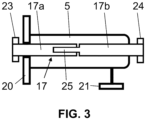
- the Figure 3 shows a section through an embodiment of the Figure 1 used electric motor 5.
- a two-part motor shaft 17 of the electric motor is provided, which is divided into two separate, concentrically running shafts 17a and 17b.
- the two separate, concentrically running shafts 17a and 17b are axially displaceable in the longitudinal direction relative to one another. They can be connected in a rotationally fixed manner via a longitudinal toothing 25.
- the Figure 4 shows a section through an embodiment of the Figure 2 used electric motor 5.
- a two-part motor shaft 17 of the electric motor 5 is provided, which is divided into two separate, concentrically running shafts 17a and 17b, which are axially displaceable against each other in the longitudinal direction and which can be connected in a rotationally fixed manner via a longitudinal toothing 25.
- the electric motor 5 is fastened to the housing of the internal combustion engine 6 by means of a fastening device 21 which can comprise a flange.
- a flange 20 which enables fastening which corresponds to the fastening of an originally present starter.
Landscapes
- Engineering & Computer Science (AREA)
- Transportation (AREA)
- Mechanical Engineering (AREA)
- Chemical & Material Sciences (AREA)
- Combustion & Propulsion (AREA)
- Automation & Control Theory (AREA)
- Hybrid Electric Vehicles (AREA)
- Connection Of Motors, Electrical Generators, Mechanical Devices, And The Like (AREA)
Priority Applications (1)
| Application Number | Priority Date | Filing Date | Title |
|---|---|---|---|
| EP24187952.7A EP4424538A3 (de) | 2018-02-02 | 2019-02-01 | Nachrüstsatz für einen kraftfahrzeugantrieb nebst verfahren |
Applications Claiming Priority (2)
| Application Number | Priority Date | Filing Date | Title |
|---|---|---|---|
| DE102018201614.3A DE102018201614A1 (de) | 2018-02-02 | 2018-02-02 | Nachrüstsatz für einen Kraftfahrzeugantrieb nebst Verfahren |
| PCT/EP2019/052459 WO2019149866A1 (de) | 2018-02-02 | 2019-02-01 | Nachrüstsatz für einen kraftfahrzeugantrieb nebst verfahren |
Related Child Applications (1)
| Application Number | Title | Priority Date | Filing Date |
|---|---|---|---|
| EP24187952.7A Division EP4424538A3 (de) | 2018-02-02 | 2019-02-01 | Nachrüstsatz für einen kraftfahrzeugantrieb nebst verfahren |
Publications (3)
| Publication Number | Publication Date |
|---|---|
| EP3746323A1 EP3746323A1 (de) | 2020-12-09 |
| EP3746323C0 EP3746323C0 (de) | 2024-07-24 |
| EP3746323B1 true EP3746323B1 (de) | 2024-07-24 |
Family
ID=65411841
Family Applications (2)
| Application Number | Title | Priority Date | Filing Date |
|---|---|---|---|
| EP19705111.3A Active EP3746323B1 (de) | 2018-02-02 | 2019-02-01 | Kraftfahrzeug mit nachgerüstetem elektrischen antrieb |
| EP24187952.7A Pending EP4424538A3 (de) | 2018-02-02 | 2019-02-01 | Nachrüstsatz für einen kraftfahrzeugantrieb nebst verfahren |
Family Applications After (1)
| Application Number | Title | Priority Date | Filing Date |
|---|---|---|---|
| EP24187952.7A Pending EP4424538A3 (de) | 2018-02-02 | 2019-02-01 | Nachrüstsatz für einen kraftfahrzeugantrieb nebst verfahren |
Country Status (5)
| Country | Link |
|---|---|
| EP (2) | EP3746323B1 (https=) |
| JP (1) | JP7493458B2 (https=) |
| DE (1) | DE102018201614A1 (https=) |
| ES (1) | ES2990035T3 (https=) |
| WO (1) | WO2019149866A1 (https=) |
Families Citing this family (1)
| Publication number | Priority date | Publication date | Assignee | Title |
|---|---|---|---|---|
| DE102024110183A1 (de) | 2024-04-11 | 2025-10-16 | Roland Heidl | Nachrüsten eines Kraftfahrzeugs umfassend eine Getriebeseitenwelle mit einem Elektromotor |
Citations (7)
| Publication number | Priority date | Publication date | Assignee | Title |
|---|---|---|---|---|
| US20090018716A1 (en) * | 2007-07-12 | 2009-01-15 | Joseph Mario Ambrosio | Parallel hybrid drive system utilizing power take off connection as transfer for a secondary energy source |
| WO2010135027A2 (en) * | 2009-03-11 | 2010-11-25 | Zero Emission Systems, Inc. | Dual mode clutch pedal for vehicle |
| US20110000721A1 (en) * | 2009-07-02 | 2011-01-06 | Thermal Motor Innovations, Llc | Hybrid parallel load assist systems and methods |
| US20110306463A1 (en) * | 2008-12-17 | 2011-12-15 | Nt Consulting International Pty, Ltd. | Automated manual transmission with hybrid drive |
| US20130152732A1 (en) * | 2011-12-19 | 2013-06-20 | David E Klingston | Off-axis motor with hybrid transmission method and system |
| WO2013113907A1 (en) * | 2012-02-02 | 2013-08-08 | Gkn Driveline International Gmbh | Drive assembly with electric machine and motor vehicle having such a drive assembly |
| KR101454868B1 (ko) * | 2013-04-18 | 2014-10-28 | 자일대우버스(주) | 듀얼 전기모터를 적용한 하이브리드 전기 자동차의 구동 시스템 |
Family Cites Families (14)
| Publication number | Priority date | Publication date | Assignee | Title |
|---|---|---|---|---|
| JP2000289476A (ja) * | 1999-04-13 | 2000-10-17 | Isuzu Motors Ltd | ハイブリッド車 |
| JP3832465B2 (ja) * | 2003-10-27 | 2006-10-11 | トヨタ自動車株式会社 | ハイブリッド車用駆動装置 |
| JP4285405B2 (ja) * | 2004-12-17 | 2009-06-24 | 日産自動車株式会社 | ハイブリッド自動車 |
| DE102005041634A1 (de) | 2005-08-26 | 2007-03-01 | Gümüs, Cem | Nachrüstsatz zur parallelen Ein- oder Auskopplung von mechanischer Energie in oder aus dem Antriebstrang eines Kraftfahrzeugs sowie Einbau- und Betriebsverfahren dafür |
| JP4986676B2 (ja) * | 2007-03-29 | 2012-07-25 | ダイハツ工業株式会社 | ハイブリッド自動車のモータ支持構造 |
| DE102008032286A1 (de) | 2008-07-09 | 2010-01-14 | Gerhard Brauer | Hybridbetrieb von vorhandenen Kraftfahrzeugen durch Nachrüstung eines Elektroantriebes mit gleichzeitig im Leerlauf betriebenen Verbrennungsmotor |
| BR112012005361A2 (pt) * | 2009-09-15 | 2023-11-21 | Kpit Cummins Infosystems Ltd | Método de conversão de um veículo convencional para híbrido |
| US9145048B2 (en) * | 2010-03-31 | 2015-09-29 | General Electric Company | Apparatus for hybrid engine control and method of manufacture same |
| ITMI20110555A1 (it) * | 2011-04-05 | 2012-10-06 | Milano Politecnico | Veicolo ibrido multimodale e dispositivo di collegamento in un sistema di trazione ibrida |
| JP6167476B2 (ja) * | 2012-06-04 | 2017-07-26 | スズキ株式会社 | ハイブリッド車両搭載の電動機用オイル循環システム |
| DE102012214457A1 (de) * | 2012-08-14 | 2014-02-20 | Zf Friedrichshafen Ag | Antriebssystem für ein Fahrzeug |
| JP6390105B2 (ja) * | 2014-02-04 | 2018-09-19 | スズキ株式会社 | ハイブリッド車両の駆動装置 |
| US20150298574A1 (en) * | 2014-04-16 | 2015-10-22 | Ford Global Technologies, Llc | Dual motor electric vehicle drive with efficiency-optimized power sharing |
| DE202017002410U1 (de) | 2017-05-02 | 2017-08-01 | Karhausen Patentverwaltung GbR (vertretungsber. Gesellschafter Robert Karhausen, 52134 Herzogenrath) | Zusatzantrieb mittels Elektromotor bei PKW zum Betrieb in Innenstädten mit Fahrverbot |
-
2018
- 2018-02-02 DE DE102018201614.3A patent/DE102018201614A1/de active Pending
-
2019
- 2019-02-01 ES ES19705111T patent/ES2990035T3/es active Active
- 2019-02-01 WO PCT/EP2019/052459 patent/WO2019149866A1/de not_active Ceased
- 2019-02-01 EP EP19705111.3A patent/EP3746323B1/de active Active
- 2019-02-01 EP EP24187952.7A patent/EP4424538A3/de active Pending
- 2019-02-01 JP JP2020563809A patent/JP7493458B2/ja active Active
Patent Citations (7)
| Publication number | Priority date | Publication date | Assignee | Title |
|---|---|---|---|---|
| US20090018716A1 (en) * | 2007-07-12 | 2009-01-15 | Joseph Mario Ambrosio | Parallel hybrid drive system utilizing power take off connection as transfer for a secondary energy source |
| US20110306463A1 (en) * | 2008-12-17 | 2011-12-15 | Nt Consulting International Pty, Ltd. | Automated manual transmission with hybrid drive |
| WO2010135027A2 (en) * | 2009-03-11 | 2010-11-25 | Zero Emission Systems, Inc. | Dual mode clutch pedal for vehicle |
| US20110000721A1 (en) * | 2009-07-02 | 2011-01-06 | Thermal Motor Innovations, Llc | Hybrid parallel load assist systems and methods |
| US20130152732A1 (en) * | 2011-12-19 | 2013-06-20 | David E Klingston | Off-axis motor with hybrid transmission method and system |
| WO2013113907A1 (en) * | 2012-02-02 | 2013-08-08 | Gkn Driveline International Gmbh | Drive assembly with electric machine and motor vehicle having such a drive assembly |
| KR101454868B1 (ko) * | 2013-04-18 | 2014-10-28 | 자일대우버스(주) | 듀얼 전기모터를 적용한 하이브리드 전기 자동차의 구동 시스템 |
Also Published As
| Publication number | Publication date |
|---|---|
| EP3746323C0 (de) | 2024-07-24 |
| JP2021525330A (ja) | 2021-09-24 |
| WO2019149866A1 (de) | 2019-08-08 |
| EP4424538A3 (de) | 2024-10-23 |
| EP4424538A2 (de) | 2024-09-04 |
| EP3746323A1 (de) | 2020-12-09 |
| DE102018201614A1 (de) | 2019-08-08 |
| ES2990035T3 (es) | 2024-11-28 |
| JP7493458B2 (ja) | 2024-05-31 |
Similar Documents
| Publication | Publication Date | Title |
|---|---|---|
| EP3429879B1 (de) | Hybridantriebsstrang für ein hybridgetriebenes kraftfahrzeug | |
| DE102004050757A1 (de) | Satz von Getrieben und Hybrid-Doppelkupplungsgetriebe | |
| DE10243375A1 (de) | Getriebe | |
| EP3406474B1 (de) | Elektrohydraulische hybridantriebsvorrichtung für ein kraftfahrzeug | |
| DE102010037451A1 (de) | Antriebssystem für ein Kraftfahrzeug und Kraftfahrzeug mit einem derartigen Antriebssystem | |
| DE102011101410A1 (de) | Hybridantrieb für Kraftfahrzeuge | |
| DE102022125314A1 (de) | Hybridfahrzeuggetriebe mit mechanischem rückwärtsgangsystem | |
| DE102021213669B4 (de) | Schleppverlustarmes Hybridgetriebe in Mischbauweise | |
| DE102019209931B4 (de) | Lastschaltbares Hybridgetriebe | |
| DE4004330C2 (de) | Zusatzantrieb für Kraftfahrzeuge mit Verbrennungsmotor | |
| EP3746323B1 (de) | Kraftfahrzeug mit nachgerüstetem elektrischen antrieb | |
| DE102013221911A1 (de) | Getriebe-Motor-Anordnung | |
| DE102021213667A1 (de) | Viergang-Hybridgetriebe in Mischbauweise | |
| DE102022202926B4 (de) | Kompaktes Dreigang-Hybridgetriebe | |
| DE102021213660B4 (de) | Kompaktes Hybridgetriebe in Mischbauweise | |
| WO2020177888A1 (de) | Hybridgetriebe für einen kraftfahrzeug-antriebsstrang, kraftfahrzeug-antriebsstrang und kraftfahrzeug damit | |
| DE102021213678A1 (de) | Kompaktes Viergang-Hybridgetriebe | |
| WO2025215248A1 (de) | Nachrüsten eines kraftfahrzeugs umfassend eine getriebeseitenwelle mit einem elektromotor | |
| DE102016204582A1 (de) | Hybridantriebsstrang für ein hybridgetriebenes Kraftfahrzeug | |
| DE102014224512B4 (de) | Antriebsstrang für ein Fahrzeug, insbesondere einen Kraftwagen | |
| DE102021213652B4 (de) | Viergang-Hybridgetriebe | |
| DE102022201151B4 (de) | Kompaktes Hybridgetriebe | |
| DE102020214534B4 (de) | Kompaktes Kraftfahrzeuggetriebe | |
| DE102022202924B4 (de) | Hybridgetriebe | |
| DE102013222725A1 (de) | Antriebsstrang für ein Fahrzeug sowie Fahrzeug mit dem Antriebsstrang |
Legal Events
| Date | Code | Title | Description |
|---|---|---|---|
| STAA | Information on the status of an ep patent application or granted ep patent |
Free format text: STATUS: UNKNOWN |
|
| STAA | Information on the status of an ep patent application or granted ep patent |
Free format text: STATUS: THE INTERNATIONAL PUBLICATION HAS BEEN MADE |
|
| PUAI | Public reference made under article 153(3) epc to a published international application that has entered the european phase |
Free format text: ORIGINAL CODE: 0009012 |
|
| STAA | Information on the status of an ep patent application or granted ep patent |
Free format text: STATUS: REQUEST FOR EXAMINATION WAS MADE |
|
| 17P | Request for examination filed |
Effective date: 20200814 |
|
| AK | Designated contracting states |
Kind code of ref document: A1 Designated state(s): AL AT BE BG CH CY CZ DE DK EE ES FI FR GB GR HR HU IE IS IT LI LT LU LV MC MK MT NL NO PL PT RO RS SE SI SK SM TR |
|
| AX | Request for extension of the european patent |
Extension state: BA ME |
|
| DAV | Request for validation of the european patent (deleted) | ||
| DAX | Request for extension of the european patent (deleted) | ||
| STAA | Information on the status of an ep patent application or granted ep patent |
Free format text: STATUS: EXAMINATION IS IN PROGRESS |
|
| 17Q | First examination report despatched |
Effective date: 20220429 |
|
| GRAP | Despatch of communication of intention to grant a patent |
Free format text: ORIGINAL CODE: EPIDOSNIGR1 |
|
| STAA | Information on the status of an ep patent application or granted ep patent |
Free format text: STATUS: GRANT OF PATENT IS INTENDED |
|
| RIC1 | Information provided on ipc code assigned before grant |
Ipc: B60K 6/40 20071001ALI20240205BHEP Ipc: B60W 30/19 20120101ALI20240205BHEP Ipc: B60W 20/30 20160101ALI20240205BHEP Ipc: B60W 20/15 20160101ALI20240205BHEP Ipc: B60W 10/111 20120101ALI20240205BHEP Ipc: B60W 10/11 20120101ALI20240205BHEP Ipc: B60W 10/08 20060101ALI20240205BHEP Ipc: B60K 6/547 20071001ALI20240205BHEP Ipc: B60K 6/405 20071001ALI20240205BHEP Ipc: B60K 6/48 20071001AFI20240205BHEP |
|
| INTG | Intention to grant announced |
Effective date: 20240301 |
|
| GRAS | Grant fee paid |
Free format text: ORIGINAL CODE: EPIDOSNIGR3 |
|
| GRAA | (expected) grant |
Free format text: ORIGINAL CODE: 0009210 |
|
| STAA | Information on the status of an ep patent application or granted ep patent |
Free format text: STATUS: THE PATENT HAS BEEN GRANTED |
|
| AK | Designated contracting states |
Kind code of ref document: B1 Designated state(s): AL AT BE BG CH CY CZ DE DK EE ES FI FR GB GR HR HU IE IS IT LI LT LU LV MC MK MT NL NO PL PT RO RS SE SI SK SM TR |
|
| REG | Reference to a national code |
Ref country code: GB Ref legal event code: FG4D Free format text: NOT ENGLISH |
|
| REG | Reference to a national code |
Ref country code: CH Ref legal event code: EP |
|
| REG | Reference to a national code |
Ref country code: IE Ref legal event code: FG4D Free format text: LANGUAGE OF EP DOCUMENT: GERMAN Ref country code: DE Ref legal event code: R096 Ref document number: 502019011732 Country of ref document: DE |
|
| U01 | Request for unitary effect filed |
Effective date: 20240819 |
|
| U07 | Unitary effect registered |
Designated state(s): AT BE BG DE DK EE FI FR IT LT LU LV MT NL PT SE SI Effective date: 20240828 |
|
| REG | Reference to a national code |
Ref country code: ES Ref legal event code: FG2A Ref document number: 2990035 Country of ref document: ES Kind code of ref document: T3 Effective date: 20241128 |
|
| PG25 | Lapsed in a contracting state [announced via postgrant information from national office to epo] |
Ref country code: NO Free format text: LAPSE BECAUSE OF FAILURE TO SUBMIT A TRANSLATION OF THE DESCRIPTION OR TO PAY THE FEE WITHIN THE PRESCRIBED TIME-LIMIT Effective date: 20241024 |
|
| PG25 | Lapsed in a contracting state [announced via postgrant information from national office to epo] |
Ref country code: GR Free format text: LAPSE BECAUSE OF FAILURE TO SUBMIT A TRANSLATION OF THE DESCRIPTION OR TO PAY THE FEE WITHIN THE PRESCRIBED TIME-LIMIT Effective date: 20241025 Ref country code: PL Free format text: LAPSE BECAUSE OF FAILURE TO SUBMIT A TRANSLATION OF THE DESCRIPTION OR TO PAY THE FEE WITHIN THE PRESCRIBED TIME-LIMIT Effective date: 20240724 |
|
| PG25 | Lapsed in a contracting state [announced via postgrant information from national office to epo] |
Ref country code: IS Free format text: LAPSE BECAUSE OF FAILURE TO SUBMIT A TRANSLATION OF THE DESCRIPTION OR TO PAY THE FEE WITHIN THE PRESCRIBED TIME-LIMIT Effective date: 20241124 |
|
| PG25 | Lapsed in a contracting state [announced via postgrant information from national office to epo] |
Ref country code: HR Free format text: LAPSE BECAUSE OF FAILURE TO SUBMIT A TRANSLATION OF THE DESCRIPTION OR TO PAY THE FEE WITHIN THE PRESCRIBED TIME-LIMIT Effective date: 20240724 |
|
| PG25 | Lapsed in a contracting state [announced via postgrant information from national office to epo] |
Ref country code: RS Free format text: LAPSE BECAUSE OF FAILURE TO SUBMIT A TRANSLATION OF THE DESCRIPTION OR TO PAY THE FEE WITHIN THE PRESCRIBED TIME-LIMIT Effective date: 20241024 |
|
| PG25 | Lapsed in a contracting state [announced via postgrant information from national office to epo] |
Ref country code: RS Free format text: LAPSE BECAUSE OF FAILURE TO SUBMIT A TRANSLATION OF THE DESCRIPTION OR TO PAY THE FEE WITHIN THE PRESCRIBED TIME-LIMIT Effective date: 20241024 Ref country code: PL Free format text: LAPSE BECAUSE OF FAILURE TO SUBMIT A TRANSLATION OF THE DESCRIPTION OR TO PAY THE FEE WITHIN THE PRESCRIBED TIME-LIMIT Effective date: 20240724 Ref country code: NO Free format text: LAPSE BECAUSE OF FAILURE TO SUBMIT A TRANSLATION OF THE DESCRIPTION OR TO PAY THE FEE WITHIN THE PRESCRIBED TIME-LIMIT Effective date: 20241024 Ref country code: IS Free format text: LAPSE BECAUSE OF FAILURE TO SUBMIT A TRANSLATION OF THE DESCRIPTION OR TO PAY THE FEE WITHIN THE PRESCRIBED TIME-LIMIT Effective date: 20241124 Ref country code: HR Free format text: LAPSE BECAUSE OF FAILURE TO SUBMIT A TRANSLATION OF THE DESCRIPTION OR TO PAY THE FEE WITHIN THE PRESCRIBED TIME-LIMIT Effective date: 20240724 Ref country code: GR Free format text: LAPSE BECAUSE OF FAILURE TO SUBMIT A TRANSLATION OF THE DESCRIPTION OR TO PAY THE FEE WITHIN THE PRESCRIBED TIME-LIMIT Effective date: 20241025 |
|
| U20 | Renewal fee for the european patent with unitary effect paid |
Year of fee payment: 7 Effective date: 20250226 |
|
| PG25 | Lapsed in a contracting state [announced via postgrant information from national office to epo] |
Ref country code: RO Free format text: LAPSE BECAUSE OF FAILURE TO SUBMIT A TRANSLATION OF THE DESCRIPTION OR TO PAY THE FEE WITHIN THE PRESCRIBED TIME-LIMIT Effective date: 20240724 Ref country code: SM Free format text: LAPSE BECAUSE OF FAILURE TO SUBMIT A TRANSLATION OF THE DESCRIPTION OR TO PAY THE FEE WITHIN THE PRESCRIBED TIME-LIMIT Effective date: 20240724 |
|
| PGFP | Annual fee paid to national office [announced via postgrant information from national office to epo] |
Ref country code: CH Payment date: 20250301 Year of fee payment: 7 |
|
| PG25 | Lapsed in a contracting state [announced via postgrant information from national office to epo] |
Ref country code: CZ Free format text: LAPSE BECAUSE OF FAILURE TO SUBMIT A TRANSLATION OF THE DESCRIPTION OR TO PAY THE FEE WITHIN THE PRESCRIBED TIME-LIMIT Effective date: 20240724 |
|
| PG25 | Lapsed in a contracting state [announced via postgrant information from national office to epo] |
Ref country code: SK Free format text: LAPSE BECAUSE OF FAILURE TO SUBMIT A TRANSLATION OF THE DESCRIPTION OR TO PAY THE FEE WITHIN THE PRESCRIBED TIME-LIMIT Effective date: 20240724 |
|
| PLBE | No opposition filed within time limit |
Free format text: ORIGINAL CODE: 0009261 |
|
| STAA | Information on the status of an ep patent application or granted ep patent |
Free format text: STATUS: NO OPPOSITION FILED WITHIN TIME LIMIT |
|
| 26N | No opposition filed |
Effective date: 20250425 |
|
| PG25 | Lapsed in a contracting state [announced via postgrant information from national office to epo] |
Ref country code: MC Free format text: LAPSE BECAUSE OF FAILURE TO SUBMIT A TRANSLATION OF THE DESCRIPTION OR TO PAY THE FEE WITHIN THE PRESCRIBED TIME-LIMIT Effective date: 20240724 |
|
| PG25 | Lapsed in a contracting state [announced via postgrant information from national office to epo] |
Ref country code: IE Free format text: LAPSE BECAUSE OF NON-PAYMENT OF DUE FEES Effective date: 20250201 |
|
| REG | Reference to a national code |
Ref country code: CH Ref legal event code: U11 Free format text: ST27 STATUS EVENT CODE: U-0-0-U10-U11 (AS PROVIDED BY THE NATIONAL OFFICE) Effective date: 20260301 |
|
| U20 | Renewal fee for the european patent with unitary effect paid |
Year of fee payment: 8 Effective date: 20260225 |
|
| PGFP | Annual fee paid to national office [announced via postgrant information from national office to epo] |
Ref country code: GB Payment date: 20260218 Year of fee payment: 8 |
|
| PGFP | Annual fee paid to national office [announced via postgrant information from national office to epo] |
Ref country code: ES Payment date: 20260317 Year of fee payment: 8 |