EP3744472B1 - Station d'assemblage de pièces d'insertion - Google Patents
Station d'assemblage de pièces d'insertion Download PDFInfo
- Publication number
- EP3744472B1 EP3744472B1 EP20176761.3A EP20176761A EP3744472B1 EP 3744472 B1 EP3744472 B1 EP 3744472B1 EP 20176761 A EP20176761 A EP 20176761A EP 3744472 B1 EP3744472 B1 EP 3744472B1
- Authority
- EP
- European Patent Office
- Prior art keywords
- insertion part
- parts
- shape
- machining
- module
- Prior art date
- Legal status (The legal status is an assumption and is not a legal conclusion. Google has not performed a legal analysis and makes no representation as to the accuracy of the status listed.)
- Active
Links
Images

Classifications
-
- B—PERFORMING OPERATIONS; TRANSPORTING
- B23—MACHINE TOOLS; METAL-WORKING NOT OTHERWISE PROVIDED FOR
- B23P—METAL-WORKING NOT OTHERWISE PROVIDED FOR; COMBINED OPERATIONS; UNIVERSAL MACHINE TOOLS
- B23P19/00—Machines for simply fitting together or separating metal parts or objects, or metal and non-metal parts, whether or not involving some deformation; Tools or devices therefor so far as not provided for in other classes
- B23P19/001—Article feeders for assembling machines
-
- B—PERFORMING OPERATIONS; TRANSPORTING
- B23—MACHINE TOOLS; METAL-WORKING NOT OTHERWISE PROVIDED FOR
- B23P—METAL-WORKING NOT OTHERWISE PROVIDED FOR; COMBINED OPERATIONS; UNIVERSAL MACHINE TOOLS
- B23P19/00—Machines for simply fitting together or separating metal parts or objects, or metal and non-metal parts, whether or not involving some deformation; Tools or devices therefor so far as not provided for in other classes
- B23P19/02—Machines for simply fitting together or separating metal parts or objects, or metal and non-metal parts, whether or not involving some deformation; Tools or devices therefor so far as not provided for in other classes for connecting objects by press fit or for detaching same
-
- B—PERFORMING OPERATIONS; TRANSPORTING
- B23—MACHINE TOOLS; METAL-WORKING NOT OTHERWISE PROVIDED FOR
- B23P—METAL-WORKING NOT OTHERWISE PROVIDED FOR; COMBINED OPERATIONS; UNIVERSAL MACHINE TOOLS
- B23P2700/00—Indexing scheme relating to the articles being treated, e.g. manufactured, repaired, assembled, connected or other operations covered in the subgroups
- B23P2700/50—Other automobile vehicle parts, i.e. manufactured in assembly lines
-
- B—PERFORMING OPERATIONS; TRANSPORTING
- B62—LAND VEHICLES FOR TRAVELLING OTHERWISE THAN ON RAILS
- B62D—MOTOR VEHICLES; TRAILERS
- B62D65/00—Designing, manufacturing, e.g. assembling, facilitating disassembly, or structurally modifying motor vehicles or trailers, not otherwise provided for
- B62D65/02—Joining sub-units or components to, or positioning sub-units or components with respect to, body shell or other sub-units or components
- B62D65/022—Transferring or handling sub-units or components, e.g. in work stations or between workstations and transportation systems
Definitions
- the invention relates to an insert part joining station according to the preamble of patent claim 1.
- Such insert parts joining stations are automated assembly workstations that are equipped with at least one industrial robot, which acts as a manipulator to feed the parts to be joined, here insert parts that are designed as thin-walled hard plastic parts, to the joining point, store them in a magazine and join them in the joining point by pressing them into sheet metal processing parts.
- JP H04 244 324 A H 11 151 625 A , H 01 212 673 A as well as from US 2019/0 134 817 A1 known.
- the problem with these solutions arises from their inappropriate structural designs. Simultaneous, differently directed joining of differently designed insert parts into sheet metal processing parts is not possible with the known joining stations.
- the object of this invention is to propose structural designs in order to join insert parts designed as thin-walled hard plastic parts in an inexpensive and safe manner.
- all functional modules for storing, feeding, magazining, feeding in an insert part feeding level and for joining the insert parts in an insert part joining level are arranged in receiving openings of a sheet metal processing part, which is positioned and fixed between these modules, resting on a support and lifting frame.
- At least one storage module for insert parts of one of the forms A, B, C and D is arranged in the insert part assembly station.
- These storage modules each consist of a module container in which an electric motor-driven vibrating conveyor and a conveyor device for emptying the module container and for feeding the respective insert parts to one of the insert part positioning magazines are arranged. This is done via alignment and feed rails separated according to the forms A, B, C and D of the insert parts.
- the insert part positioning magazines which are mounted on magazine base frames, contain insert part positioning disks that can be exchangeably pivoted in partial steps with magazine disks that can be lifted out from the insert part feed sections and are equipped with a gripping jaw system.
- the articulated arm robots with which the insert part positioning holders are lifted out of the insert part positioning discs and removed by means of a holding gripper, are also equipped with an insertion ram as an insert part tool on their tool head, which can be assigned to the insert parts of forms A, B, C and D.
- Encapsulated fittings of a control section for coordinating the process sequence and module functions are also arranged on the foundation level of an insert part joining station.
- Storage sections, insert parts feed sections, magazine sections, insert parts feed stations and control sections are arranged next to one another on both sides of a processing part holding and processing section. Depending on the dimensions and shape of the respective processing part equipped with insert parts, this section arrangement can be used to create compactly structured insert parts joining stations, placed in a common safety enclosure.
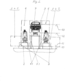
- FIG. 1 and Fig. 2 The partial views of the insert parts joining station 1 shown show four articulated arm robots 6.1 with tool heads 6.2 and insertion rams 6.3 arranged on two individual components of a foundation plate 2 as functional modules.
- the sheet metal processing part 9 is a car body, which is positioned and fixed on a support and lifting frame 7.1. In receiving openings (not shown) of this body sheet metal part, insert parts (also not shown) are to be inserted by pressing on all sides and joined in different directions using the four articulated arm robots 6.1 and their insertion ram 6.3 accommodated in the tool head 6.2.
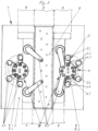
- the insert or joining parts (not shown) in the different shapes and sizes A, B, C and D, which are filled into the module containers 3.5 of the four storage modules 3.1, 3.2, 3.3 and 3.4, are functionally and sequentially connected to these insert part positioning magazines 5.1 and the magazine disks 5.3 arranged thereon and which can be removed, via alignment and feed rails 4.1.
- Fig. 2 and in Fig. 3 The structures and levels of automatically controllable insert parts joining stations 1 are shown depending on the processing part.
- the physical station structures formed by these form space-saving in Fig. 2 For example, a body in ⁇ -form and in Fig. 3 a rectangular body, each of which is provided with a safety enclosure (not shown).
Landscapes
- Engineering & Computer Science (AREA)
- Mechanical Engineering (AREA)
- Automatic Assembly (AREA)
Claims (5)
- Poste d'assemblage de pièces d'insertion, qui est réalisé dans une structure modulaire modifiable à sections, afin d'amener simultanément différentes pièces d'insertion, réalisées sous forme de pièces en matière plastique dure à paroi mince, et de les insérer par pression et de les assembler par auto-serrage, orientées de tous les côtés, dans des ouvertures de réception traversantes, ainsi que dimensionnées et formées de manière appropriée, de pièces d'usinage de type tôle, avec un outil de type poussoir, caractérisé en ce que sur et au-dessus d'un plan de fondation (10), dans un plan d'agencement de modules (11) d'un poste d'assemblage de pièces d'insertion, au moins• une section de stockage (3) avec au moins un module de stockage (3.1) pour des pièces d'insertion d'une forme A, un module de stockage (3.2) pour des pièces d'insertion d'une forme B, un module de stockage (3.3) pour des pièces d'insertion d'une forme C et un module de stockage (3.4) pour des pièces d'insertion d'une forme D, constitués respectivement d'un contenant de module (3.5) dans lequel sont agencés un transporteur vibrant entraîné par moteur électrique et un appareil de transport pour les pièces d'insertion pour le vidage du contenant de module ainsi que pour l'amenée à l'un des magasins de positionnement de pièces d'insertion (5.1),• une section d'amenée de pièces d'insertion (4) avec des rails d'alignement et d'amenée (4.1) pour des pièces d'insertion alignées et à amener individuellement dans les formes A, B, C et D séparément,• une section de magasinage (5), dans laquelle sont agencés des positionnements de pièces d'insertion dans au moins l'un des magasins de positionnement de pièces d'insertion (5.1), qui sont montés sur un châssis de magasin, et respectivement un disque de positionnement de pièces d'insertion (5.2) pivotant par étapes partielles avec des disques de magasin soulevables (5.3), qui sont équipés d'un système de mâchoires de préhension pour le prélèvement sûr par la tête d'outil (6.2) du poste d'approvisionnement en pièces d'insertion, et• une section d'approvisionnement en pièces d'insertion (6), qui est constituée d'au moins un robot à bras articulé (6.1), qui est équipé d'une pince de maintien pour les disques de magasin soulevables (5.3) et d'un poussoir d'insertion (6.3) sur sa tête d'outil (6.2) en tant qu'outil de pièce d'insertion et pouvant être affecté aux pièces d'insertion des formes A, B, C et D, sont réalisées et agencées dans un plan d'amenée de pièces d'insertion (12),en ce qu'une section de maintien et d'usinage de pièces d'usinage (7) avec un bâti de support et de levage (7.1) pour une pièce d'usinage (9) est positionnée dans un plan d'assemblage de pièces d'insertion supérieur (13),en ce qu'une section de commande (8) pour la coordination du déroulement du processus et des fonctions des modules est agencée sur le plan de fondation (10),en ce que de part et d'autre d'une section de maintien et d'usinage de pièces d'usinage (7), des sections de stockage (3), des sections d'amenée de pièces d'insertion (4), des sections de magasinage (5), des sections d'approvisionnement en pièces d'insertion (6) ainsi que des armatures encapsulées de sections de commande (8) sont agencées les unes à côté des autres eten ce qu'en fonction des dimensions et de la forme d'une pièce d'usinage (9) dans laquelle les pièces d'insertion doivent être assemblées dans les formes A, B, C et D, un poste d'assemblage de pièces d'insertion (1) à structure compacte, placé dans une enceinte de sécurité commune, est agencé.
- Poste d'assemblage de pièces d'insertion selon la revendication 1, caractérisé en ce que le plan de fondation (10) est réalisé sous forme de plaque de fondation (2) qui, en fonction d'un agencement et d'un nombre variables des modules• modules de stockage (3.1 à 3.4) avec contenants de modules (3.5),• magasins de positionnement de pièces d'insertion (5.1) avec disques de positionnement de pièces d'insertion (5.2),• robot à bras articulé (6.1) avec têtes d'outils (6.2) et poussoirs d'insertion (6.3) ainsi que cadre d'appui et de maintien d'un• châssis de support et de levage (7.1) réalisé par le type, la structure et le dimensionnement de la pièce d'usinage (9),• forme un plan d'agencement de modules (11) commun et est formée au choix sous forme de• plaque rectangulaire,• plaque circulaire ou• plaque en forme de cadre et est réalisée pour une• utilisation de la surface de fondation indépendante de la plaque.
- Poste d'assemblage de pièces d'insertion selon les revendications 1 et 2, caractérisé en ce qu'un magasin de positionnement de pièces d'insertion (5.1) d'une section de magasinage (5) comprend plusieurs disques de positionnement de pièces d'insertion (5.2) pivotant par étapes partielles, montés sur un châssis de magasin, avec des anneaux de réception de positionnement soulevables, réalisés dans des agencements de trame et d'espacement différents pour• des pièces d'insertion d'une des formes A, B, C ou D,• des pièces d'insertion de plusieurs formes A, B, C et D.
- Poste d'assemblage de pièces d'insertion selon les revendications 1 à 3, caractérisé en ce que les pièces d'insertion à assembler avec un robot à bras articulé (6.1) sont• des pièces d'insertion d'une forme A, des douilles,• des pièces d'insertion d'une forme B, des chevilles,• des pièces d'insertion d'une forme C, des cônes,• des pièces d'insertion d'une forme D, des bouchons et des pièces en matière plastique dure à paroi mince fabriquées dans d'autres formes, qui sont reçues individuellement et orientées en position sur la tête d'outil (6.2) avec une tête de maintien à air d'aspiration, sont maintenues pendant l'insertion par un poussoir d'insertion (6.3) respectif dans des ouvertures d'une pièce d'usinage (9).
- Poste d'assemblage de pièces d'insertion selon la revendication 2, caractérisé en ce que la plaque de fondation (2) est équipée d'un réseau de trous d'ajustage et de fixation étroitement espacés pour les modules à placer dans différentes positions verticales et à différentes distances fonctionnelles.
Applications Claiming Priority (1)
| Application Number | Priority Date | Filing Date | Title |
|---|---|---|---|
| DE102019003668.9A DE102019003668A1 (de) | 2019-05-27 | 2019-05-27 | Einsetzteile-Fügestation |
Publications (3)
| Publication Number | Publication Date |
|---|---|
| EP3744472A1 EP3744472A1 (fr) | 2020-12-02 |
| EP3744472C0 EP3744472C0 (fr) | 2024-11-06 |
| EP3744472B1 true EP3744472B1 (fr) | 2024-11-06 |
Family
ID=71105207
Family Applications (1)
| Application Number | Title | Priority Date | Filing Date |
|---|---|---|---|
| EP20176761.3A Active EP3744472B1 (fr) | 2019-05-27 | 2020-05-27 | Station d'assemblage de pièces d'insertion |
Country Status (4)
| Country | Link |
|---|---|
| EP (1) | EP3744472B1 (fr) |
| DE (1) | DE102019003668A1 (fr) |
| ES (1) | ES2998493T3 (fr) |
| PL (1) | PL3744472T3 (fr) |
Families Citing this family (3)
| Publication number | Priority date | Publication date | Assignee | Title |
|---|---|---|---|---|
| JP2023063894A (ja) * | 2021-10-25 | 2023-05-10 | 住友重機械工業株式会社 | 把持装置、ロボット、ロボットシステム、嵌合方法、ロボットの制御方法、及びプログラム |
| EP4420822A1 (fr) * | 2023-02-21 | 2024-08-28 | SMA Sächsische Maschinen- und Anlagenbau GmbH | Outil de pose pour écrous d'expansion, bouchons et analogues |
| CN117862831B (zh) * | 2024-01-17 | 2024-09-24 | 深圳市序佑科技有限公司 | 一种车载显示模组生产用自动组装设备 |
Citations (1)
| Publication number | Priority date | Publication date | Assignee | Title |
|---|---|---|---|---|
| DE202017101643U1 (de) * | 2017-03-21 | 2018-05-08 | Kuka Systems Gmbh | Fertigungsstation |
Family Cites Families (10)
| Publication number | Priority date | Publication date | Assignee | Title |
|---|---|---|---|---|
| DD234249A1 (de) | 1985-01-28 | 1986-03-26 | Elektrogeraete Ingbuero Veb | Industrierobotergefuehrte fuegeeinrichtung |
| JPH01212673A (ja) * | 1988-02-19 | 1989-08-25 | Honda Motor Co Ltd | グロメットの取付け方法 |
| DD288776A5 (de) | 1989-11-01 | 1991-04-11 | Fz D. Werkzeugmaschinenbaues,De | Einrichtung zum automatischen montieren komplexer baugruppen |
| JP2586222B2 (ja) * | 1991-01-31 | 1997-02-26 | 三菱自動車工業株式会社 | プラグの自動挿入装置 |
| JPH11151625A (ja) * | 1997-11-14 | 1999-06-08 | Sanko Co Ltd | グロメット挿着システム |
| DE102005041679A1 (de) | 2005-04-13 | 2006-10-19 | Sasit-Industrietechnik Gmbh Zwickau | Verfahren zum mechanischen Setzen von Spreizmuttern und/oder Tüllen in Verankerungskonstruktionen sowie Vorrichtung zu seiner Durchführung |
| DE102013227146A1 (de) | 2013-12-23 | 2015-06-25 | Daimler Ag | Verfahren zum automatisierten Montieren an einem Montagearbeitsplatz,sowie zugehöriger automatisierter Montagearbeitsplatz |
| DE102015014221B4 (de) * | 2015-11-04 | 2017-06-14 | Daimler Ag | Roboterwerkzeug und Verfahren zum Montieren von Stopfen, insbesondere für Kraftwagen |
| DE102016120462A1 (de) | 2016-10-26 | 2018-04-26 | Wika Schweiz Ag | Modul-System für Montagemanipulatoren |
| US10639796B2 (en) * | 2017-11-03 | 2020-05-05 | Fanuc America Corporation | Vehicle e-coat drain plug insertion tool |
-
2019
- 2019-05-27 DE DE102019003668.9A patent/DE102019003668A1/de active Pending
-
2020
- 2020-05-27 PL PL20176761.3T patent/PL3744472T3/pl unknown
- 2020-05-27 ES ES20176761T patent/ES2998493T3/es active Active
- 2020-05-27 EP EP20176761.3A patent/EP3744472B1/fr active Active
Patent Citations (1)
| Publication number | Priority date | Publication date | Assignee | Title |
|---|---|---|---|---|
| DE202017101643U1 (de) * | 2017-03-21 | 2018-05-08 | Kuka Systems Gmbh | Fertigungsstation |
Also Published As
| Publication number | Publication date |
|---|---|
| EP3744472A1 (fr) | 2020-12-02 |
| DE102019003668A1 (de) | 2020-12-03 |
| PL3744472T3 (pl) | 2025-05-19 |
| EP3744472C0 (fr) | 2024-11-06 |
| ES2998493T3 (en) | 2025-02-20 |
Similar Documents
| Publication | Publication Date | Title |
|---|---|---|
| EP3744472B1 (fr) | Station d'assemblage de pièces d'insertion | |
| EP3391987B1 (fr) | Procédé de soudage de parties de tôles découpées | |
| EP0977651A1 (fr) | Procede et dispositif de fabrication de pieces complexes | |
| EP1008521A2 (fr) | Dispositif pour alimenter des groupes de produits plats empilés, notemment des biscuits, dans des récipients d'emballage | |
| EP3995267B1 (fr) | Dispositif de préhension pour dispositif de manutention d'une machine d'usinage | |
| DE10013975A1 (de) | Adaptives Werkstück-Spann- und Handlingssystem | |
| DE102008032909B4 (de) | Verfahren und Fertigungseinrichtung zum Fertigen von Rohkarosserien von Fahrzeugen | |
| DE4212178A1 (de) | Automatisierte Montageeinrichtung | |
| EP3672763B1 (fr) | Système et procédé de positionnement et de serrage | |
| EP2969464A1 (fr) | Procédé et dispositif servant à équiper des pièces moulées par injection | |
| DE102018131785B4 (de) | Verfahren sowie Abstapelelement zur automatisierten Handhabung von Werkstücken | |
| WO2020187481A1 (fr) | Installation de transport pour déplacer au moins une pièce à usiner en forme de plaque | |
| DE102017206136B4 (de) | System zum Transportieren von unterschiedlich ausgestalteten Bauteilen | |
| AT507778B1 (de) | Vorrichtung zur herstellung von paletten | |
| EP4046764B1 (fr) | Dispositif d'assemblage, ainsi que procédé | |
| EP4166864B1 (fr) | Procédé et dispositif de montage pour le montage automatisé d'un cadre pour un élément de conduit d'air | |
| EP1125869B1 (fr) | Dispositif d'assemblage | |
| DE102017116176A1 (de) | Tasten-Bearbeitung und -Montage mittels Trays | |
| EP0094338A2 (fr) | Dispositif de manipulation robotisé | |
| EP1927427A2 (fr) | Dispositif d'introduction et/ou l'éclusage de pièces dans un procédé de fabrication | |
| EP2217515A2 (fr) | Dispositif de palettisation, procédé de chargement et/ou de déchargement de palettes, de pièces, de plateaux, d'emballages à bulles, de récipients de transport de petites charges ou analogues à l'aide d'un dispositif de palettisation, et procédé de traitement, de montage ou analogue de pièces | |
| EP4383975B1 (fr) | Magasin de composants et installation de montage de composants sur un rail de support | |
| EP4188671A1 (fr) | Procédé d'emballage pour pointes de pipette ou récipients médicaux à réaction, appareil d'emballage et système de moulage par injection | |
| DE29919961U1 (de) | Vorrichtung zum Vereinzeln von elektrischen oder elektronischen Substraten aus eine Vielzahl solcher Substrate aufweisenden Mehrfachsubstraten | |
| EP0767042B1 (fr) | Système de manipulation pour une machine à mouler par injection des matières plastiques et procédé pour insérer des inserts |
Legal Events
| Date | Code | Title | Description |
|---|---|---|---|
| PUAI | Public reference made under article 153(3) epc to a published international application that has entered the european phase |
Free format text: ORIGINAL CODE: 0009012 |
|
| STAA | Information on the status of an ep patent application or granted ep patent |
Free format text: STATUS: THE APPLICATION HAS BEEN PUBLISHED |
|
| AK | Designated contracting states |
Kind code of ref document: A1 Designated state(s): AL AT BE BG CH CY CZ DE DK EE ES FI FR GB GR HR HU IE IS IT LI LT LU LV MC MK MT NL NO PL PT RO RS SE SI SK SM TR |
|
| AX | Request for extension of the european patent |
Extension state: BA ME |
|
| STAA | Information on the status of an ep patent application or granted ep patent |
Free format text: STATUS: REQUEST FOR EXAMINATION WAS MADE |
|
| 17P | Request for examination filed |
Effective date: 20210601 |
|
| RBV | Designated contracting states (corrected) |
Designated state(s): AL AT BE BG CH CY CZ DE DK EE ES FI FR GB GR HR HU IE IS IT LI LT LU LV MC MK MT NL NO PL PT RO RS SE SI SK SM TR |
|
| RIC1 | Information provided on ipc code assigned before grant |
Ipc: B62D 65/02 20060101ALN20240424BHEP Ipc: B23P 19/02 20060101ALI20240424BHEP Ipc: B23P 19/00 20060101AFI20240424BHEP |
|
| GRAP | Despatch of communication of intention to grant a patent |
Free format text: ORIGINAL CODE: EPIDOSNIGR1 |
|
| STAA | Information on the status of an ep patent application or granted ep patent |
Free format text: STATUS: GRANT OF PATENT IS INTENDED |
|
| INTG | Intention to grant announced |
Effective date: 20240606 |
|
| GRAS | Grant fee paid |
Free format text: ORIGINAL CODE: EPIDOSNIGR3 |
|
| GRAA | (expected) grant |
Free format text: ORIGINAL CODE: 0009210 |
|
| STAA | Information on the status of an ep patent application or granted ep patent |
Free format text: STATUS: THE PATENT HAS BEEN GRANTED |
|
| AK | Designated contracting states |
Kind code of ref document: B1 Designated state(s): AL AT BE BG CH CY CZ DE DK EE ES FI FR GB GR HR HU IE IS IT LI LT LU LV MC MK MT NL NO PL PT RO RS SE SI SK SM TR |
|
| REG | Reference to a national code |
Ref country code: GB Ref legal event code: FG4D Free format text: NOT ENGLISH |
|
| REG | Reference to a national code |
Ref country code: CH Ref legal event code: EP |
|
| REG | Reference to a national code |
Ref country code: DE Ref legal event code: R096 Ref document number: 502020009667 Country of ref document: DE |
|
| REG | Reference to a national code |
Ref country code: IE Ref legal event code: FG4D Free format text: LANGUAGE OF EP DOCUMENT: GERMAN |
|
| U01 | Request for unitary effect filed |
Effective date: 20241206 |
|
| U07 | Unitary effect registered |
Designated state(s): AT BE BG DE DK EE FI FR IT LT LU LV MT NL PT RO SE SI Effective date: 20250102 |
|
| REG | Reference to a national code |
Ref country code: ES Ref legal event code: FG2A Ref document number: 2998493 Country of ref document: ES Kind code of ref document: T3 Effective date: 20250220 |
|
| PG25 | Lapsed in a contracting state [announced via postgrant information from national office to epo] |
Ref country code: HR Free format text: LAPSE BECAUSE OF FAILURE TO SUBMIT A TRANSLATION OF THE DESCRIPTION OR TO PAY THE FEE WITHIN THE PRESCRIBED TIME-LIMIT Effective date: 20241106 Ref country code: IS Free format text: LAPSE BECAUSE OF FAILURE TO SUBMIT A TRANSLATION OF THE DESCRIPTION OR TO PAY THE FEE WITHIN THE PRESCRIBED TIME-LIMIT Effective date: 20250306 |
|
| PG25 | Lapsed in a contracting state [announced via postgrant information from national office to epo] |
Ref country code: NO Free format text: LAPSE BECAUSE OF FAILURE TO SUBMIT A TRANSLATION OF THE DESCRIPTION OR TO PAY THE FEE WITHIN THE PRESCRIBED TIME-LIMIT Effective date: 20250206 |
|
| PG25 | Lapsed in a contracting state [announced via postgrant information from national office to epo] |
Ref country code: GR Free format text: LAPSE BECAUSE OF FAILURE TO SUBMIT A TRANSLATION OF THE DESCRIPTION OR TO PAY THE FEE WITHIN THE PRESCRIBED TIME-LIMIT Effective date: 20250207 |
|
| PG25 | Lapsed in a contracting state [announced via postgrant information from national office to epo] |
Ref country code: RS Free format text: LAPSE BECAUSE OF FAILURE TO SUBMIT A TRANSLATION OF THE DESCRIPTION OR TO PAY THE FEE WITHIN THE PRESCRIBED TIME-LIMIT Effective date: 20250206 |
|
| U20 | Renewal fee for the european patent with unitary effect paid |
Year of fee payment: 6 Effective date: 20250528 |
|
| PG25 | Lapsed in a contracting state [announced via postgrant information from national office to epo] |
Ref country code: SM Free format text: LAPSE BECAUSE OF FAILURE TO SUBMIT A TRANSLATION OF THE DESCRIPTION OR TO PAY THE FEE WITHIN THE PRESCRIBED TIME-LIMIT Effective date: 20241106 |
|
| PGFP | Annual fee paid to national office [announced via postgrant information from national office to epo] |
Ref country code: PL Payment date: 20250515 Year of fee payment: 6 |
|
| PG25 | Lapsed in a contracting state [announced via postgrant information from national office to epo] |
Ref country code: SK Free format text: LAPSE BECAUSE OF FAILURE TO SUBMIT A TRANSLATION OF THE DESCRIPTION OR TO PAY THE FEE WITHIN THE PRESCRIBED TIME-LIMIT Effective date: 20241106 |
|
| PG25 | Lapsed in a contracting state [announced via postgrant information from national office to epo] |
Ref country code: CZ Free format text: LAPSE BECAUSE OF FAILURE TO SUBMIT A TRANSLATION OF THE DESCRIPTION OR TO PAY THE FEE WITHIN THE PRESCRIBED TIME-LIMIT Effective date: 20241106 |
|
| PLBE | No opposition filed within time limit |
Free format text: ORIGINAL CODE: 0009261 |
|
| STAA | Information on the status of an ep patent application or granted ep patent |
Free format text: STATUS: NO OPPOSITION FILED WITHIN TIME LIMIT |
|
| PGFP | Annual fee paid to national office [announced via postgrant information from national office to epo] |
Ref country code: ES Payment date: 20250630 Year of fee payment: 6 |
|
| 26N | No opposition filed |
Effective date: 20250807 |
|
| REG | Reference to a national code |
Ref country code: CH Ref legal event code: H13 Free format text: ST27 STATUS EVENT CODE: U-0-0-H10-H13 (AS PROVIDED BY THE NATIONAL OFFICE) Effective date: 20251223 |
|
| PG25 | Lapsed in a contracting state [announced via postgrant information from national office to epo] |
Ref country code: CH Free format text: LAPSE BECAUSE OF NON-PAYMENT OF DUE FEES Effective date: 20250531 |
|
| GBPC | Gb: european patent ceased through non-payment of renewal fee |
Effective date: 20250527 |
|
| PG25 | Lapsed in a contracting state [announced via postgrant information from national office to epo] |
Ref country code: MC Free format text: LAPSE BECAUSE OF FAILURE TO SUBMIT A TRANSLATION OF THE DESCRIPTION OR TO PAY THE FEE WITHIN THE PRESCRIBED TIME-LIMIT Effective date: 20241106 |