EP3743193B1 - Verschlussvorrichtung, filtereinheit für ein barrieresystem sowie barrieresystem, insbesondere isolator - Google Patents
Verschlussvorrichtung, filtereinheit für ein barrieresystem sowie barrieresystem, insbesondere isolator Download PDFInfo
- Publication number
- EP3743193B1 EP3743193B1 EP19730248.2A EP19730248A EP3743193B1 EP 3743193 B1 EP3743193 B1 EP 3743193B1 EP 19730248 A EP19730248 A EP 19730248A EP 3743193 B1 EP3743193 B1 EP 3743193B1
- Authority
- EP
- European Patent Office
- Prior art keywords
- lid
- filter cartridge
- barrier system
- air duct
- opening
- Prior art date
- Legal status (The legal status is an assumption and is not a legal conclusion. Google has not performed a legal analysis and makes no representation as to the accuracy of the status listed.)
- Active
Links
Images




Classifications
-
- F—MECHANICAL ENGINEERING; LIGHTING; HEATING; WEAPONS; BLASTING
- F16—ENGINEERING ELEMENTS AND UNITS; GENERAL MEASURES FOR PRODUCING AND MAINTAINING EFFECTIVE FUNCTIONING OF MACHINES OR INSTALLATIONS; THERMAL INSULATION IN GENERAL
- F16K—VALVES; TAPS; COCKS; ACTUATING-FLOATS; DEVICES FOR VENTING OR AERATING
- F16K1/00—Lift valves or globe valves, i.e. cut-off apparatus with closure members having at least a component of their opening and closing motion perpendicular to the closing faces
- F16K1/16—Lift valves or globe valves, i.e. cut-off apparatus with closure members having at least a component of their opening and closing motion perpendicular to the closing faces with pivoted closure-members
- F16K1/18—Lift valves or globe valves, i.e. cut-off apparatus with closure members having at least a component of their opening and closing motion perpendicular to the closing faces with pivoted closure-members with pivoted discs or flaps
- F16K1/22—Lift valves or globe valves, i.e. cut-off apparatus with closure members having at least a component of their opening and closing motion perpendicular to the closing faces with pivoted closure-members with pivoted discs or flaps with axis of rotation crossing the valve member, e.g. butterfly valves
- F16K1/226—Shaping or arrangements of the sealing
- F16K1/2263—Shaping or arrangements of the sealing the sealing being arranged on the valve seat
-
- B—PERFORMING OPERATIONS; TRANSPORTING
- B01—PHYSICAL OR CHEMICAL PROCESSES OR APPARATUS IN GENERAL
- B01D—SEPARATION
- B01D46/00—Filters or filtering processes specially modified for separating dispersed particles from gases or vapours
- B01D46/42—Auxiliary equipment or operation thereof
- B01D46/4272—Special valve constructions adapted to filters or filter elements
-
- F—MECHANICAL ENGINEERING; LIGHTING; HEATING; WEAPONS; BLASTING
- F16—ENGINEERING ELEMENTS AND UNITS; GENERAL MEASURES FOR PRODUCING AND MAINTAINING EFFECTIVE FUNCTIONING OF MACHINES OR INSTALLATIONS; THERMAL INSULATION IN GENERAL
- F16K—VALVES; TAPS; COCKS; ACTUATING-FLOATS; DEVICES FOR VENTING OR AERATING
- F16K1/00—Lift valves or globe valves, i.e. cut-off apparatus with closure members having at least a component of their opening and closing motion perpendicular to the closing faces
- F16K1/16—Lift valves or globe valves, i.e. cut-off apparatus with closure members having at least a component of their opening and closing motion perpendicular to the closing faces with pivoted closure-members
- F16K1/18—Lift valves or globe valves, i.e. cut-off apparatus with closure members having at least a component of their opening and closing motion perpendicular to the closing faces with pivoted closure-members with pivoted discs or flaps
- F16K1/22—Lift valves or globe valves, i.e. cut-off apparatus with closure members having at least a component of their opening and closing motion perpendicular to the closing faces with pivoted closure-members with pivoted discs or flaps with axis of rotation crossing the valve member, e.g. butterfly valves
- F16K1/226—Shaping or arrangements of the sealing
- F16K1/2263—Shaping or arrangements of the sealing the sealing being arranged on the valve seat
- F16K1/2265—Shaping or arrangements of the sealing the sealing being arranged on the valve seat with a channel- or U-shaped seal covering a central body portion
-
- F—MECHANICAL ENGINEERING; LIGHTING; HEATING; WEAPONS; BLASTING
- F16—ENGINEERING ELEMENTS AND UNITS; GENERAL MEASURES FOR PRODUCING AND MAINTAINING EFFECTIVE FUNCTIONING OF MACHINES OR INSTALLATIONS; THERMAL INSULATION IN GENERAL
- F16K—VALVES; TAPS; COCKS; ACTUATING-FLOATS; DEVICES FOR VENTING OR AERATING
- F16K27/00—Construction of housing; Use of materials therefor
- F16K27/02—Construction of housing; Use of materials therefor of lift valves
- F16K27/0209—Check valves or pivoted valves
- F16K27/0227—Check valves or pivoted valves with the valve members swinging around an axis located at the edge of or outside the valve member
-
- F—MECHANICAL ENGINEERING; LIGHTING; HEATING; WEAPONS; BLASTING
- F16—ENGINEERING ELEMENTS AND UNITS; GENERAL MEASURES FOR PRODUCING AND MAINTAINING EFFECTIVE FUNCTIONING OF MACHINES OR INSTALLATIONS; THERMAL INSULATION IN GENERAL
- F16K—VALVES; TAPS; COCKS; ACTUATING-FLOATS; DEVICES FOR VENTING OR AERATING
- F16K27/00—Construction of housing; Use of materials therefor
- F16K27/02—Construction of housing; Use of materials therefor of lift valves
- F16K27/0209—Check valves or pivoted valves
- F16K27/0227—Check valves or pivoted valves with the valve members swinging around an axis located at the edge of or outside the valve member
- F16K27/0232—Check valves or pivoted valves with the valve members swinging around an axis located at the edge of or outside the valve member the valve member retained by a removable closure
-
- B—PERFORMING OPERATIONS; TRANSPORTING
- B01—PHYSICAL OR CHEMICAL PROCESSES OR APPARATUS IN GENERAL
- B01D—SEPARATION
- B01D2265/00—Casings, housings or mounting for filters specially adapted for separating dispersed particles from gases or vapours
- B01D2265/02—Non-permanent measures for connecting different parts of the filter
- B01D2265/022—Bayonet connecting means
-
- B—PERFORMING OPERATIONS; TRANSPORTING
- B01—PHYSICAL OR CHEMICAL PROCESSES OR APPARATUS IN GENERAL
- B01D—SEPARATION
- B01D2271/00—Sealings for filters specially adapted for separating dispersed particles from gases or vapours
- B01D2271/02—Gaskets, sealings
-
- B—PERFORMING OPERATIONS; TRANSPORTING
- B01—PHYSICAL OR CHEMICAL PROCESSES OR APPARATUS IN GENERAL
- B01D—SEPARATION
- B01D46/00—Filters or filtering processes specially modified for separating dispersed particles from gases or vapours
- B01D46/0002—Casings; Housings; Frame constructions
- B01D46/0005—Mounting of filtering elements within casings, housings or frames
-
- F—MECHANICAL ENGINEERING; LIGHTING; HEATING; WEAPONS; BLASTING
- F16—ENGINEERING ELEMENTS AND UNITS; GENERAL MEASURES FOR PRODUCING AND MAINTAINING EFFECTIVE FUNCTIONING OF MACHINES OR INSTALLATIONS; THERMAL INSULATION IN GENERAL
- F16K—VALVES; TAPS; COCKS; ACTUATING-FLOATS; DEVICES FOR VENTING OR AERATING
- F16K31/00—Actuating devices; Operating means; Releasing devices
- F16K31/02—Actuating devices; Operating means; Releasing devices electric; magnetic
- F16K31/04—Actuating devices; Operating means; Releasing devices electric; magnetic using a motor
- F16K31/041—Actuating devices; Operating means; Releasing devices electric; magnetic using a motor for rotating valves
- F16K31/042—Actuating devices; Operating means; Releasing devices electric; magnetic using a motor for rotating valves with electric means, e.g. for controlling the motor or a clutch between the valve and the motor
-
- F—MECHANICAL ENGINEERING; LIGHTING; HEATING; WEAPONS; BLASTING
- F16—ENGINEERING ELEMENTS AND UNITS; GENERAL MEASURES FOR PRODUCING AND MAINTAINING EFFECTIVE FUNCTIONING OF MACHINES OR INSTALLATIONS; THERMAL INSULATION IN GENERAL
- F16K—VALVES; TAPS; COCKS; ACTUATING-FLOATS; DEVICES FOR VENTING OR AERATING
- F16K31/00—Actuating devices; Operating means; Releasing devices
- F16K31/02—Actuating devices; Operating means; Releasing devices electric; magnetic
- F16K31/04—Actuating devices; Operating means; Releasing devices electric; magnetic using a motor
- F16K31/041—Actuating devices; Operating means; Releasing devices electric; magnetic using a motor for rotating valves
- F16K31/043—Actuating devices; Operating means; Releasing devices electric; magnetic using a motor for rotating valves characterised by mechanical means between the motor and the valve, e.g. lost motion means reducing backlash, clutches, brakes or return means
- F16K31/045—Actuating devices; Operating means; Releasing devices electric; magnetic using a motor for rotating valves characterised by mechanical means between the motor and the valve, e.g. lost motion means reducing backlash, clutches, brakes or return means with torque limiters
Definitions
- the invention relates to a closure device for a filter unit for joint releasable insertion into a return air or exhaust air duct of a barrier system, comprising a base body, an opening in the base body that can be delimited on the periphery by an annular seal, a cover that is between an open position in which the opening is open , and a closed position in which it rests sealingly against the ring seal for optional opening and closing of the opening is adjustable and which is penetrated by an imaginary longitudinal axis, the cover being pivotably articulated to the base body by means of at least one swivel joint penetrated by a pivot axis.
- the invention also relates to a filter unit for detachable insertion into a return air or exhaust air duct of a barrier system.
- the invention also relates to a barrier system, in particular an isolator, preferably for pharmaceutical applications, with a processing room and a return air or exhaust air duct and at least one filter unit designed according to the concept of the invention and releasably inserted into the return air or exhaust air duct.
- a barrier system in particular an isolator, preferably for pharmaceutical applications, with a processing room and a return air or exhaust air duct and at least one filter unit designed according to the concept of the invention and releasably inserted into the return air or exhaust air duct.
- Exchangeable filter units for pharmaceutical barrier systems are known.
- Such a filter unit is for example in the DE 20 2010 017 347 A1 described.
- an opening facing the barrier system is opened or closed by means of a translationally adjustable cover, a spindle drive penetrating the filter unit being provided for translational adjustment of the cover, which has a central part of the interior space enclosed by the filter means of the filter unit.
- the disadvantage of the known system is that essential, even air distribution in the interior is hindered by the spindle drive.
- An alternative filter unit is in the EP 2 666 532 B1 described.
- the known filter unit is characterized by a piston and a piston receptacle in the interior of the filter unit.
- a uniform air distribution is also adversely affected by the built-in components in the interior.
- a further alternative filter unit is known, which is characterized in that from the DE 20 2010 017 347 A1 known spindle drive is releasably associated with a drive motor which can be placed on the spindle drive from the outside.
- a drive motor which can be placed on the spindle drive from the outside.
- a filter unit is also known from practice which comprises a closure device with a U-shaped ring seal which delimits an opening on the circumferential side.
- the opening can optionally be opened or closed by means of a cover which can be pivoted about a pivot axis.
- the pivot axis extends through a closure section of the cover, that is to say that section which closes the opening, in the vertical longitudinal center plane of the cover.
- the vertical longitudinal center plane is arranged in such a way that both the geometric center of the closure section and the normal vector of the closure section lie in the vertical longitudinal center plane in the closed position of the lid.
- the pivot axis runs centrally through the circularly contoured cover, so it coincides with or is arranged parallel to a diameter line of the Opening.
- the shafts of rotation of the cover are diametrically opposed to one another or the pivot axis of the cover passes through its center.
- the problem is that the cover rests against the ring seal in its open position and, when it is moved into its closed position, can roll or push the ring seal out of its fastening.
- the invention is based on the object of specifying a simply constructed filter unit, in particular a filter cartridge, for detachable insertion into a return air or exhaust air duct of a barrier system, in which the ring seal is reliably prevented from rolling out.
- the object is to specify a barrier system, in particular an isolator, preferably for pharmaceutical applications with such a filter unit.
- features disclosed in accordance with the device should also apply and be claimable as disclosed in accordance with the method.
- features disclosed in accordance with the method should also apply and be claimable as disclosed in accordance with the device.
- the invention is based on the idea of the lowest possible frictional forces or frictional forces only for a very short time between the ring seal and the cover during its adjustment movement between to create the open position and the closed position. According to the invention, a double eccentricity is therefore provided, which leads to a considerable reduction in both the level of the friction force and the duration of the friction force.
- the double eccentricity leads to the fact that the cover or its closure section only comes into contact with the ring seal for a very short period of time or only for a very small pivoting range of approximately 0 ° to 10 °, based on the closed position.
- the two eccentricities also mean that the cover is not adjusted with an exclusively rotary adjustment movement, but rather the mainly rotary adjustment movement includes a translational component, which means that the cover exerts less flexing action on the ring seal.
- the double eccentricity means that the cover in its open position protrudes unevenly from the opening, for example at an opening angle of 90 °. While a large part of the cover protrudes from one side of the opening, only a small part of the cover can protrude from the other side of the opening at the same time. As a result, installation space and transport costs can be saved.
- the plane of the closure section is defined by the closure section in the closed position of the lid, it being at the level of the contact between the closure section and the ring seal.
- the cover is pivotably mounted along the pivot axis on two opposite swivel joints, preferably on at least one, more preferably on two shaft sections coinciding with the pivot axis.
- the swivel joints can have sliding or roller bearings.
- the base body has a flange on which the ring seal is arranged and the flange and / or the ring seal is / are designed such that in the open position of the cover at least one cavity between the flange and the Ring seal is formed. The seal can thus be pressed into the cavity when the cover is in contact with it.
- a cavity faces the cover and / or a cavity is arranged such that it faces a barrier system that can be connected to the closure device.
- the cavity facing the cover means that tolerance compensation can take place and the frictional forces that arise between the seal and the cover can be further reduced.
- the cavity facing the barrier system also means that only small forces are required to connect the locking device to the barrier system, preferably to screw it in there via a bayonet lock.
- the ring seal has a largely circular or C-shaped cross section.
- a seal with a circular cross section can be a commercially available O-ring, which is inexpensive.
- the seal with a C-shaped cross section offers the possibility of forming the cavity.
- the ring seal is designed to widen conically at least in sections in the direction of the axis of rotation. This can create frictional forces between the seal and the cover can be further reduced and a high-density closed position can be ensured.
- the filter unit according to the invention opens up the possibility of securely closing the interior space on the side opposite the opening of an opening-free housing section of the filter unit, which is preferred to prevent any toxic particles from being discharged through sealed openings, as described in the prior art Spindle solution are possible, safe to avoid. A leak cannot be caused by a seal that has been kneaded out.
- the invention also includes a barrier system, in particular an isolator, preferably for pharmaceutical applications, which is further preferably designed as described at the outset and insofar particularly preferably has decontamination means for decontaminating the processing space, preferably hydrogen peroxide.
- the barrier system according to the invention is characterized by a filter unit, or preferably a plurality of such filter units, which is detachably inserted into the return air or exhaust air duct and designed according to the concept of the invention.
- a filter unit 1 designed as a filter cartridge is shown schematically, inserted into a return air or exhaust air duct 2 of a barrier system 3, preferably designed as a pharmaceutical isolator, comprising a processing space 4.
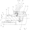
- the filter unit 1 has an essentially cylindrical structure and is in Fig. 1 shown in a longitudinal sectional view. A centric one can be seen along the way The longitudinal axis A extending along the length of the filter unit 1, in the present case in the form of the longitudinal center axis, which coincides with an insertion direction or axis for inserting the filter unit into the position shown on the barrier system 3.
- the longitudinal axis A passes through a front opening 6 of the filter unit 1 through which (when the opening 6 is open) gas, in this case air, can flow axially from the processing space 4 into an interior 7 of the filter unit 1, starting from which the gas is radially outward in a hollow cylinder contoured filter medium 8 flows in, from which the gas then flows out (filtered) in the radial direction outward into the return air or exhaust air duct 2 again.
- gas in this case air
- the opening 6 is formed in a closure device 28 which has a base body 30 and which is arranged on the end of the filter unit 1 opposite the housing section 9.
- the opening 6 is delimited on the circumferential side by an annular seal 11 or the annular seal 11 is arranged on a flange 32.
- a cover 10 designed and arranged as a flap is provided, which can be pivoted about a pivot axis S, preferably perpendicular to the longitudinal axis A, between the closed position shown and an open position indicated by dashed lines.
- the cover 10 can be pivoted outside the preferably elastomeric ring seal 11 at the opening edge of the opening 6, which in the closed position ensures a tight seal.
- this ring seal 11 or alternatively an additional ring seal, lies axially against the barrier system 3 in a sealing manner.
- a sufficient one Sealing pressure is ensured by a corresponding axial force application of the filter unit 1 along the longitudinal axis A towards the barrier system 3, this axial force for example by a locking mechanism and / or locking screws and / or a bayonet lock or the like.
- Fixing and / or positioning means can be applied in a manner known per se.
- the cover 10 is fixedly connected to the cover 10 and assigned opposite shaft sections 12, 13, via which the cover 10 is pivotably mounted on bearings 50 with respect to a housing 14 of the filter unit.
- a releasable coupling 15 shown only schematically as a black box, for torque transmission.
- This clutch 15 is composed of a shaft section-side clutch output section 16 and a torque-transmitting, barrier system-side clutch drive section 17 of a barrier system-side and housing-fixed drive device 18, in this case an automatic drive device 18 with electric motor 19
- the clutch drive section 17 is pivoted and, as a result, the clutch output section 16 and thus the shaft section 13 with the cover 10 in turn via the torque-transmitting clutch.
- FIGS Figures 8 and 9 Alternative solution concepts for torque transmission between drive devices 18 and the shaft section 13 and thus the cover 10 are shown in FIGS Figures 8 and 9 and discussed in detail in the corresponding description.
- the direct transmission of a torque from a drive device 18 to a drive journal or shaft section 13 can, however, also advantageously be provided.
- an axial bearing journal projecting into the cover 10 can also be provided there.
- the flap or the cover 10 can also be supported in a very general manner in a different manner, for example by means of one or two bearing pins protruding into the flap along the pivot axis S.
- the electric motor 19 is preferably controllable in such a way that the cover 10 assumes a defined opening pivot angle, which is preferably adjustable. It is conceivable to specify this open position via a limit switch, which can preferably be fixed in different positions, in particular the barrier system, for setting the desired opening angle.
- a closing spring means 5 comprising torsion springs are identified by the reference number 5, against the spring force of which the cover 10 can be swiveled from the closed swivel position into an open swivel position.
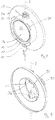
- the Figures 2 to 5 show the closure device 28 on its own with a cover 10 in the closed position ( Figs. 2 and 3 ) and a cover 10 adjusted by an opening pivot angle of 90 ° into an open position ( Figures 4 and 5 ).
- the open position can also have a smaller opening angle, the closed position being present at an angle of 0 °.
- the base body 30 has four evenly spaced locking catches 34 of a bayonet lock at its end facing the barrier system 3 for detachable fixation on the barrier system 3.
- the cover 10 has a preferably circular closure section 36, which is considered to be that section which closes the opening 6. In the closed position, the closure section 36 rests against the ring seal 11 in a sealing manner.
- the closure section 36 is supported by two opposing base sections 38 connected in a rotationally fixed manner to the closure section 36.
- a first eccentricity is particularly in the Fig. 1 and 7th recognizable, since the pivot axis S does not coincide with a closure section plane E 1 in which the closure section 36 lies. Rather, a distance A 1 is provided between the closure section plane E 1 and the pivot axis S.
- the closure section plane E 1 and the pivot axis S run genuinely parallel to one another.
- a second eccentricity can be seen when looking at the Figures 4 and 5 as in Fig. 6 .
- the pivot axis S is namely arranged at a distance A 2 from a vertical longitudinal center plane E 2 , which extends vertically through the center of the cover (10) in its closed position.
- the vertical longitudinal center plane E 2 and the pivot axis S run genuinely parallel to one another.
- the lid 10 in Fig. 4 protrudes significantly shorter from the opening 6 than in Fig. 5 .
- a housing 14 When arranged according to Fig. 1 in a housing 14 thus protrudes into the majority of the cover 10 into the interior space 7, while only a small part of the cover 10 protrudes from the side of the opening 6 on the barrier system side.
- the Fig. 6 and 7th illustrate the double eccentricity according to the invention.
- the closing section plane E 1 is defined by the closing section 36 in its closed position.
- the vertical longitudinal center plane E 2 extends through the cover 10 in its closed position vertically in the center.
- the first eccentricity results from the distance A 1 between the pivot axis S and the Closure section level E 1 , like Fig. 7 indicates.
- the second eccentricity results from the distance A 2 between the pivot axis S and the vertical longitudinal center plane E 2 , as Fig. 6 indicates.
- the Fig. 7 shows in particular the ring seal 11, which is arranged on the flange 32.
- a first cavity 42 is arranged on the side of the flange 32 on the barrier system side and a second cavity 44 is arranged on the side of the flange 32 facing the cover 10.
- the cavities 42 and 44 are arranged between the flange 32 and the ring seal 11.
- the ring seal 11 has an approximately C-shaped cross section and, with two base sections 46, engages behind fastening grooves 48 on the flange 32.
- Fig. 7 shows that the ring seal 11 is designed to widen conically at least in sections in the direction of the axis of rotation S. As a result, the cover 10 can easily be brought into the closed position resting on the ring seal 11.
- a securing means which preferably irreversibly secures the cover 10 in its closed position.
- the securing means can, for example, be pushed onto at least one of the shaft sections 12, 13 and latched there in order to prevent a rotation of the cover 10.
- the Fig. 8 shows a section of a barrier system according to the invention comprising a filter unit 1 and a drive device 18 for transmitting torque from the drive device 18 to the cover 10, preferably via a shaft section 13.
- the drive device is designed as an electric or pneumatic rotary drive drive device 18.1 that generates a rotary movement that is controlled by a Articulated connection, for example a toggle lever, is transmitted to the shaft section 13.
- a releasable coupling or coupling between the drive device 18.1, in particular the articulated connection 51 and the shaft section 13 can be provided so that the filter unit 1 or the shaft section 13 of the filter unit can be released from the drive device 18, 18.1 in order to facilitate removal and / or to allow the filter unit to be changed.
- the barrier system in particular the filter unit 1, has one or two sensor devices which detect the position of the lid 10, in particular the end positions of the lid 10 in a fully open and in a fully closed position and preferably to a control unit of the Communicating the barrier system.
- the drive device 18 can be designed so that when a fully open position of the cover 10 or an open end position of the cover 10 is reached, a stop is reached so that the drive device moves to a block or a stop to reach the open or opened end position of the cover 10 . It can be provided that at least one sensor device is designed in such a way that the operating parameters of the drive device, for example current intensity, voltage, pneumatic pressure or the like, are recorded and used as indirect measured variables for recording at least one end position of the cover 10.
- FIG Fig. 9 An alternative embodiment of the drive device 18 is shown in FIG Fig. 9 shown, in which the linear drive device 18.2 is designed as a pneumatic linear drive, to which a piston rod 52 is assigned, which converts the linear movement of the drive device 18.2 in connection with a linkage device 53 into a rotational movement or a Torque translated to the shaft section 13. Otherwise, a mechanical stop can also be implemented here, which limits the movement of the drive device, at the latest when the cover 10 has reached the completely open and / or the completely closed position or position. A releasable coupling or coupling to the shaft section 13 can also be provided for the articulation device 53.
Landscapes
- Engineering & Computer Science (AREA)
- General Engineering & Computer Science (AREA)
- Mechanical Engineering (AREA)
- Chemical & Material Sciences (AREA)
- Chemical Kinetics & Catalysis (AREA)
- Filtering Of Dispersed Particles In Gases (AREA)
Description
- Die Erfindung betrifft eine Verschlussvorrichtung für eine Filtereinheit zum gemeinsamen lösbaren Einsetzen in einen Rückluft- oder Abluftkanal eines Barrieresystems, umfassend einen Grundkörper, eine von einer Ringdichtung umfangsseitig begrenzbare Öffnung in dem Grundkörper, einen Deckel, der zwischen einer Öffnungsstellung, in welcher die Öffnung geöffnet ist, und einer Schließstellung, in welcher er dichtend an der Ringdichtung anliegt zum wahlweisen Öffnen und Schließen der Öffnung verstellbar ist und welcher von einer gedachten Längsachse durchsetzt ist, wobei der Deckel mittels mindestens eines von einer Schwenkachse durchgriffenen Drehgelenks schwenkbar an dem Grundkörper angelenkt ist.
- Zudem betrifft die Erfindung eine Filtereinheit zum lösbaren Einsetzen in einen Rückluft- oder Abluftkanal eines Barrieresystems.
- Ferner betrifft die Erfindung ein Barrieresystem, insbesondere einen Isolator, bevorzugt für pharmatechnische Anwendungen, mit einem Bearbeitungsraum und einem Rückluft- oder Abluftkanal sowie mindestens einer lösbar in den Rückluft- oder Abluftkanal eingesetzten, nach dem Konzept der Erfindung ausgebildeten Filtereinheit.
- Austauschbare Filtereinheiten für pharmatechnische Barrieresysteme sind bekannt. Eine solche Filtereinheit ist beispielsweise in der
DE 20 2010 017 347 A1 beschrieben. Bei der bekannten Lösung wird eine dem Barrieresystem zugewandte Öffnung mittels eines translatorisch vestellbaren Deckels geöffnet oder verschlossen, wobei zum translatorischen Verstellen des Deckels ein die Filtereinheit durchsetzender Spindeltrieb vorgesehen ist, der einen zentrischen Teil des von Filtermitteln der Filtereinheit umschlossenen Innenraums beansprucht. Nachteilig bei dem bekannten System ist, dass eine essentielle gleichmäßige Luftverteilung im Innenraum durch den Spindeltrieb behindert wird. - Eine alternative Filtereinheit ist in der
EP 2 666 532 B1 beschrieben. Die bekannte Filtereinheit zeichnet sich durch einen Kolben und eine Kolbenaufnahme im Innenraum der Filtereinheit aus. Bei der bekannten Lösung wird ebenfalls eine gleichmäßige Luftverteilung durch die Einbauten im Innenraum nachteilig beeinflusst. - Aus der
WO 2017/088075 A1 ist eine weitere alternative Filtereinheit bekannt, die sich dadurch auszeichnet, dass dem aus derDE 20 2010 017 347 A1 bekannten Spindeltrieb lösbar ein Antriebsmotor zugeordnet ist, der von außen auf den Spindeltrieb aufsetzbar ist. Es bestehen auch hier die im Zusammenhang mit derDE 20 2010 017 347 A 1 beschriebenen Nachteile. - Aus der Praxis ist auch eine Filtereinheit bekannt, welche eine Verschlussvorrichtung mit einer U-förmigen Ringdichtung umfasst, die eine Öffnung umfangsseitig begrenzt. Die Öffnung ist wahlweise öffenbar oder verschließbar mittels eines Deckels, der um eine Schwenkachse verschwenkbar ist. Die Schwenkachse durchgreift einen Verschlussabschnitt des Deckels, also derjenigen Abschnitt, der die Öffnung verschließt, in der Vertikallängsmittelebene des Deckels. Die Vertikallängsmittelebene ist so angeordnet, dass sowohl das geometrische Zentrum des Verschlussabschnitts als auch der Normalenvektor des Verschlussabschnitts in Schließstellung des Deckels in der Vertikallängsmittelebene liegt. Mit anderen Worten verläuft die Schwenkachse mittig durch den kreisförmig konturierten Deckel, fällt also zusammen mit oder ist parallel angeordnet zu einer Durchmesserlinie der Öffnung. Die Rotationswellen des Deckels liegen sich diametral gegenüber bzw. die Schwenkachse des Deckels durchläuft dessen Zentrum. Problematisch ist jedoch, dass der Deckel in seiner Offenstellung an der Ringdichtung anliegt und bei Verstellung in seine Schließstellung die Ringdichtung aus ihrer Befestigung herauswalken bzw. herausdrücken kann. Es entstehen hohe Reibungskräfte oder Reibungskräfte für die gesamte Verschwenkdauer zwischen der Ringdichtung und dem Deckel. Daher sind auch hohe Momente nötig, um den Deckel zu verstellen.
- Schließlich sind aus dem Stand der Technik auch noch die Entgegenhaltungen
CN204522561U sowie dieUS 4 759 781 A bekannt. - Ausgehend von dem vorgenannten Stand der Technik liegt der Erfindung die Aufgabe zugrunde eine einfach aufgebaute Filtereinheit, insbesondere Filterpatrone, zum lösbaren Einsetzen in einen Rückluft- oder Abluftkanal eines Barrieresystems anzugeben, bei welcher ein herauswalken der Ringdichtung sicher verhindert ist.
- Ferner besteht die Aufgabe darin ein Barrieresystem, insbesondere einen Isolator, bevorzugt für pharmatechnische Anwendungen mit einer solchen Filtereinheit anzugeben.
- Diese Aufgabe wird hinsichtlich der Verschlussvorrichtung mit den Merkmalen des Anspruchs 1 gelöst.
- Vorteilhafte Weiterbildungen der Erfindung sind in den Unteransprüchen angegeben.
- Zur Vermeidung von Wiederholungen sollen vorrichtungsgemäß offenbarte Merkmale auch als verfahrensgemäß offenbart gelten und beanspruchbar sein. Ebenso sollen verfahrensgemäß offenbarte Merkmale auch als vorrichtungsgemäß offenbart gelten und beanspruchbar sein.
- Der Erfindung liegt der Gedanke zugrunde, möglichst geringe Reibungskräfte oder Reibungskräfte lediglich für sehr kurze Zeit zwischen der Ringdichtung und dem Deckel bei dessen Verstellbewegung zwischen der Offenstellung und der Schließstellung entstehen zu lassen. Es ist also erfindungsgemäß eine Doppelexzentrizität vorgesehen, welche zu einer erheblichen Reduzierung sowohl der Reibungskrafthöhe als auch der Reibungskraftdauer führt. Die Doppelexzentrizität führt nämlich dazu, dass der Deckel bzw. dessen Verschlussabschnitt nur für einen sehr kurzen Zeitraum bzw. nur für einen sehr geringen Verschwenkungsbereich von etwa 0° bis 10°, bezogen auf die Schließstellung, überhaupt in Kontakt mit der Ringdichtung kommt. Die beiden Exzentrizitäten führen auch dazu, dass der Deckel nicht mit einer ausschließlich rotatorischen Verstellbewegung verstellt wird, sondern die hauptsächlich rotatorische Verstellbewegung einen translatorischen Anteil umfasst, der dazu führt, dass der Deckel eine geringere Walkungswirkung auf die Ringdichtung ausübt. Zudem führt die Doppelexzentrizität dazu, dass der Deckel in seiner Offenstellung beispielsweise bei einem Öffnungswinkel von 90° ungleichmäßig aus der Öffnung herausragt. Während ein großer Teil des Deckels aus einer Seite der Öffnung ragt, kann gleichzeitig lediglich ein kleiner Teil des Deckels aus der anderen Seite der Öffnung ragen. Dadurch können Bauraum und Transportkosten eingespart werden.
- Die Verschlussabschnittsebene ist definiert durch den Verschlussabschnitt in der Schließstellung des Deckels, wobei sie auf Höhe des Kontaktes zwischen dem Verschlussabschnitt und der Ringdichtung liegt.
- Bei einer bevorzugten Ausführungsform der Verschlussvorrichtung nach der Erfindung ist der Deckel entlang der Schwenkachse an zwei sich gegenüberliegenden Drehgelenken, bevorzugt an mindestens einer, weiter bevorzugt an zwei mit der Schwenkachse zusammenfallenden Wellenabschnitten, verschwenkbar gelagert ist. Die Drehgelenke können Gleit- oder Wälzlager aufweisen.
- Bei einer weiteren bevorzugten Ausführungsform der Verschlussvorrichtung nach der Erfindung weist der Grundkörper einen Flansch auf, an welchem die Ringdichtung angeordnet ist und der Flansch und/oder die Ringdichtung derart ausgebildet ist/sind, dass in Öffnungsstellung des Deckels mindestens ein Hohlraum zwischen dem Flansch und der Ringdichtung ausgebildet ist. Die Dichtung kann somit bei daran anliegendem Deckel in den Hohlraum gedrückt werden.
- Gemäß einer weiteren bevorzugten Ausführungsform der Verschlussvorrichtung nach der Erfindung ist ein Hohlraum dem Deckel zugewandt und/oder ein Hohlraum so angeordnet, dass er einem an die Verschlussvorrichtung anschließbaren Barrieresystem zugewandt ist. Der dem Deckel zugewandte Hohlraum führt dazu, dass ein Toleranzausgleich erfolgen kann und entstehende Reibungskräfte zwischen der Dichtung und dem Deckel weiter reduziert werden können. Der dem Barrieresystem zugewandte Hohlraum führt ebenfalls dazu, dass nur geringe Kräfte nötig sind, um die Verschlussvorrichtung mit dem Barrieresystem zu verbinden, bevorzugt dieses dort über einen Bajonettverschluss einzudrehen.
- Gemäß einer weiteren bevorzugten Ausführungsform der Verschlussvorrichtung nach der Erfindung weist die Ringdichtung einen weitgehend kreisförmigen oder einen C-förmigen Querschnitt auf. Bei einer Dichtung mit kreisförmigem Querschnitt kann es sich um einen handelsüblichen O-Ring handeln, welcher kostengünstig ist. Die Dichtung mit C-förmigem Querschnitt bietet die Möglichkeit der Ausbildung des Hohlraums.
- Es ist gemäß einer weiteren bevorzugten Ausführungsform der Verschlussvorrichtung nach der Erfindung denkbar, dass die Ringdichtung zumindest abschnittsweise in Richtung Drehachse konisch aufweitend ausgebildet ist. Dadurch können entstehende Reibungskräfte zwischen der Dichtung und dem Deckel weiter reduziert werden und eine hochdichte Schließstellung gewährleistet werden.
- Die erfindungsgemäße Filtereinheit eröffnet die Möglichkeit, den Innenraum auf der der Öffnung gegenüberliegenden Seite von einem durchbruchfreien Gehäuseabschnitt der Filtereinheit sicher zu verschließen, was bevorzugt ist, um ein Austragen von ggf. toxischen Partikeln durch abgedichtete Durchbrüche, wie diese bei der im Stand der Technik beschriebenen Spindellösung möglich sind, sicher zu vermeiden. Ein Leck kann auch nicht durch eine herausgewalkte Dichtung entstehen.
- Die Erfindung umfasst auch ein Barrieresystem, insbesondere einen Isolator, bevorzugt für pharmatechnische Anwendungen, welcher weiter bevorzugt ausgebildet ist, wie eingangs beschrieben und insofern insbesondere bevorzugt Dekontaminationsmittel zum Dekontaminieren des Bearbeitungsraums, bevorzugt Wasserstoffperoxid aufweist. Das erfindungsgemäße Barrieresystem zeichnet sich aus durch eine lösbar in den Rückluft- oder Abluftkanal eingesetzte, nach dem Konzept der Erfindung ausgebildete Filtereinheit oder bevorzugt mehrerer solcher Filtereinheiten.
- Weitere Vorteile, Merkmale und Einzelheiten der Erfindung ergeben sich aus der nachfolgenden Beschreibung bevorzugter Ausführungsbeispiele sowie anhand der Zeichnungen.
- Diese zeigen in:
- Fig. 1
- ein Ausführungsbeispiel einer nach dem Konzept der Erfindung ausgebildeten, an einem nur ausschnittsweise dargestellten Barrieresystem festgelegten Filtereinheit zur Verstellung der Klappe in einer Schnittansicht entlang einer Linie I-I nach
Fig. 6 , - Fig. 2
- eine perspektivische Draufsicht auf eine erfindungsgemäße Verschlussvorrichtung nach
Fig. 1 in Schließstellung, - Fig. 3
- eine perspektivische Unteransicht auf eine erfindungsgemäße Verschlussvorrichtung nach
Fig. 1 in Schließstellung, - Fig. 4
- eine perspektivische Draufsicht auf eine erfindungsgemäße Verschlussvorrichtung nach
Fig. 1 in Öffnungsstellung, - Fig. 5
- eine perspektivische Unteransicht auf eine erfindungsgemäße Verschlussvorrichtung nach
Fig. 1 in Öffnungsstellung, - Fig. 6
- eine Draufsicht auf eine erfindungsgemäße Verschlussvorrichtung gemäß
Fig. 1 in Schließstellung, und - Fig. 7
- eine Detailansicht des Ausschnitts VII nach
Fig. 1 . - In den Figuren sind gleiche Elemente und Elemente mit der gleichen Funktion mit den gleichen Bezugszeichen gekennzeichnet.
- In
Fig. 1 ist schematisch eine als Filterpatrone ausgebildete Filtereinheit 1 gezeigt, eingesetzt in einen Rückluft- oder Abluftkanal 2 eines bevorzugt als pharmatechnischer Isolator ausgebildeten Barrieresystems 3, umfassend einen Bearbeitungsraum 4. Die Filtereinheit 1 hat einen im Wesentlichen zylindrischen Aufbau und ist inFig. 1 in einer Längsschnittansicht gezeigt. Zu erkennen ist eine zentrische, sich entlang der Längserstreckung der Filtereinheit 1 erstreckende Längsachse A, vorliegend in Form der Längsmittelachse, die mit einer Einsetzrichtung bzw. -achse zum Einsetzen der Filtereinheit in die gezeigte Position am Barrieresystem 3 zusammenfällt. Die Längsachse A durchsetzt eine stirnseitige Öffnung 6 der Filtereinheit 1 durch die (bei geöffneter Öffnung 6) Gas, vorliegend Luft axial aus dem Bearbeitungsraum 4 in einen Innenraum 7 der Filtereinheit 1 einströmen kann, ausgehend von dem das Gas in radialer Richtung nach außen in hohlzylindrisch konturierte Filtermittel 8 einströmt, aus denen das Gas dann (gefiltert) in radialer Richtung nach außen in den Rückluft- oder Abluftkanal 2 wieder ausströmt. Auf der der Öffnung 6 axial gegenüberliegenden Seite ist der Innenraum der Filtereinheit 1 von einem Gehäuseabschnitt 9 durchbrechungsfrei verschlossen. - Die Öffnung 6 ist in einer einen Grundkörper 30 aufweisenden Verschlussvorrichtung 28 ausgebildet, die an dem dem Gehäuseabschnitt 9 gegenüberliegenden Ende der Filtereinheit 1 angeordnet ist. Die Öffnung 6 ist umfangsseitig von einer Ringdichtung 11 begrenzt bzw. die Ringdichtung 11 ist an einem Flansch 32 angeordnet.
- Zum Öffnen und Schließen der Öffnung 6 und damit des Innenraums 7 ist ein als Klappe ausgebildeter und angeordneter Deckel 10 vorgesehen, der zwischen der gezeigten Schließstellung und einer strichliert angedeuteten Öffnungsstellung um eine sich bevorzugt senkrecht zur Längsachse A erstreckenden Schwenkachse S verschwenkbar ist.
- Zu erkennen ist, dass der Deckel 10 außerhalb der bevorzugt elastomeren Ringdichtung 11 am Öffnungsrand der Öffnung 6 verschwenkbar ist, die in Schließstellung einen dichten Verschluss sicherstellt. Gleichzeitig liegt diese Ringdichtung 11, oder alternativ eine zusätzliche Ringdichtung dichtend axial am Barrieresystem 3 an. Eine ausreichende Dichtungspressung wird durch eine entsprechende Axialkraftbeaufschlagung der Filtereinheit 1 entlang der Längsachse A hin zum Barrieresystem 3 sichergestellt, wobei diese Axialkraft beispielsweise durch einen Rastmechanismus, und/oder Verschlussschrauben und/oder einen Bajonettverschluss od.dgl. Fixier- und/oder Positioniermittel in an sich bekannter Weise aufbringbar ist.
- Entlang der Schwenkachse S sind dem Deckel 10 fest mit dem Deckel 10 verbundene, sich gegenüberliegende Wellenabschnitte 12, 13 zugeordnet, über die der Deckel 10 gegenüber einem Gehäuse 14 der Filtereinheit verschwenkbar an Lagern 50 gelagert ist. Endseitig an dem in der Zeichnungsebene linken Wellenabschnitt 13 befindet sich eine lediglich schematisch als Black-Box dargestellte lösbare Kupplung 15 zur Drehmomentübertragung. Diese Kupplung 15 setzt sich zusammen aus einem wellenabschnittsseitigen Kupplungsabtriebsabschnitt 16 und einem drehmomentübertragend mit diesem verbundenen, barrieresystemseitigen Kupplungsantriebsabschnitt 17 einer barrieresystemseitigen und dort gehäusefesten Antriebseinrichtung 18, vorliegend einer automatischen Antriebseinrichtung 18 mit Elektromotor 19. Durch Rotieren des Elektromotors 19 wird über eine entsprechende Welle 20 der Kupplungsantriebabschnitt 17 verschwenkt und hierdurch wiederum über die drehmomentübertragende Kupplung der Kupplungsabtriebsabschnitt 16 und somit der Wellenabschnitt 13 mit Deckel 10.
- Alternative Lösungskonzepte zur Drehmomentsübertragung zwischen Antriebseinrichtungen 18 und dem Wellenabschnitt 13 und damit dem Deckel 10 sind in den
Figuren 8 und 9 dargestellt und in der entsprechenden Beschreibung im Detail erörtert. Die direkte Übertragung eines Drehmoments von einer Antriebsvorrichtung 18 auf einen Antriebszapfen oder Wellenabschnitt 13 kann jedoch ebenfalls vorteilhaft vorgesehen sein. - Anstatt des Wellenabschnitts 12 kann beispielsweise dort auch ein axialer in den Deckel 10 hineinragender Lagerzapfen vorgesehen sein. Selbstverständlich ist auch ganz allgemein eine Lagerung der Klappe bzw. des Deckels 10 auf andere Weise möglich, beispielsweise über einen oder zwei entlang der Schwenkachse S in die Klappe hineinragenden, Lagerzapfen.
- Der Elektromotor 19 ist bevorzugt derart ansteuerbar, dass der Deckel 10 einen definierten Öffnungsschwenkwinkel einnimmt, der bevorzugt einstellbar ist. Denkbar ist es, diese Öffnungsstellung über einen Endschalter vorzugeben, der bevorzugt in unterschiedlichen Positionen, insbesondere des Barrieresystem zur Einstellung des gewünschten Öffnungswinkels festlegbar ist.
- Mit dem Bezugszeichen 5 sind eine Torsionfeder umfassende Schließfedermittel 5 gekennzeichnet, gegen deren Federkraft der Deckel 10 aus der Verschlussschwenkposition in eine Öffnungsschwenkposition verschwenkbar ist.
- Die
Figuren 2 bis 5 zeigen die Verschlussvorrichtung 28 in Alleinstellung mit einem Deckel 10 in Schließstellung (Fig. 2 und 3 ) und einem demgegenüber um einen Öffnungsschwenkwinkel von 90° in eine Öffnungsstellung verstellten Deckel 10 (Fig. 4 und 5 ). Die Öffnungsstellung kann jedoch auch einen geringeren Öffnungswinkel aufweisen, wobei bei einem Winkel von 0° die Schließstellung vorliegt. Es ist zu erkennen, dass der Grundkörper 30 an seinem dem Barrieresystem 3 zuwendbaren Ende vier gleichmäßig beabstandete Verschlussrasten 34 eines Bajonettverschluss aufweist zur lösbaren Fixierung am Barrieresystem 3. - Der Deckel 10 weist einen bevorzugt kreisrunden Verschlussabschnitt 36 auf, welcher als derjenigen Abschnitt gilt, der die Öffnung 6 verschließt. Der Verschlussabschnitt 36 liegt in Schließstellung dichtend an der Ringdichtung 11 an. Der Verschlussabschnitt 36 ist getragen von zwei mit dem Verschlussabschnitt 36 drehfest verbundenen sich gegenüberliegenden Basisabschnitten 38. Die Basisabschnitten 38 bilden zusammen mit den Wellenabschnitten 12 und 13 jeweils ein Drehgelenk 40 aus, welche von der Schwenkachse S durchgriffen sind.
- Eine erste Exzentrizität ist insbesondere in den
Fig. 1 und7 erkennbar, da die Schwenkachse S nicht mit einer Verschlussabschnittsebene E1 zusammenfällt, in welcher der Verschlussabschnitt 36 liegt. Vielmehr ist zwischen der Verschlussabschnittsebene E1 und der Schwenkachse S ein Abstand A1 vorgesehen. Die Verschlussabschnittsebene E1 und die Schwenkachse S verlaufen echt parallel zueinander. Eine zweite Exzentrizität zeigt sich in Zusammenschau derFig. 4 und 5 sowie inFig. 6 . Die Schwenkachse S ist nämlich mit einem Abstand A2 zu einer Vertikallängsmittelebene E2 angeordnet, die den Deckel (10) in dessen Schließstellung vertikal mittig durchgreift. Die Vertikallängsmittelebene E2 und die Schwenkachse S verlaufen echt parallel zueinander. Daraus resultiert, dass der Deckel 10 inFig. 4 erheblich kürzer aus der Öffnung 6 herausragt als inFig. 5 . Bei Anordnung nachFig. 1 in einem Gehäuse 14 ragt somit in Großteil des Deckels 10 in den Innenraum 7 hinein, während lediglich ein Kleinteil des Deckels 10 aus der barrieresystemseitigen Seite der Öffnung 6 ragt. - Die
Fig. 6 und7 verdeutlichen die erfindungsgemäße Doppelexzentrizität. Die Verschlussabschnittsebene E1 ist definiert durch den Verschlussabschnitt 36 in dessen Schließstellung. Die Vertikallängsmittelebene E2 durchgreift den Deckel 10 in dessen Schließstellung vertikal mittig. Die erste Exzentrizität ergibt sich durch den Abstand A1 zwischen der Schwenkachse S und der Verschlussabschnittsebene E1, wieFig. 7 zeigt. Die zweite Exzentrizität ergibt sich durch den Abstand A2 zwischen der Schwenkachse S und der Vertikallängsmittelebene E2, wieFig. 6 zeigt. - Die
Fig. 7 zeigt insbesondere die Ringdichtung 11, welche an dem Flansch 32 angeordnet ist. Ein erster Hohlraum 42 ist an der barrieresystemseitigen Seite des Flansches 32 und ein zweiter Hohlraum 44 ist an der dem Deckel 10 zugewandten Seite des Flansches 32 angeordnet. Die Hohlräume 42 und 44 sind zwischen dem Flansch 32 und der Ringdichtung 11 angeordnet. Die Ringdichtung 11 weist einen annähernd C-förmigen Querschnitt auf und hintergreift mit zwei Sockelabschnitten 46 Befestigungsnuten 48 am Flansch 32. - Insbesondere
Fig. 7 zeigt, dass die Ringdichtung 11 zumindest abschnittsweise in Richtung Drehachse S konisch aufweitend ausgebildet ist. Dadurch kann der Deckel 10 leicht in die an der Ringdichtung 11 anliegende Schließstellung gebracht werden. - Nicht dargestellt ist ein Sicherungsmittel, welches vorzugsweise irreversibel den Deckel 10 in seiner Schließstellung sichert. Das Sicherungsmittel ist beispielsweise auf zumindest einen der Wellenabschnitte 12, 13 aufschiebbar und dort verrastbar, um eine Rotation des Deckels 10 zu verhindern.
- Die
Fig. 8 zeigt einen Ausschnitt aus einem erfindungsgemäßen Barrieresystem umfassend eine Filtereinheit 1 und eine Antriebseinrichtung 18 zur Übertragung von Drehmomenten, von der Antriebseinrichtung 18 auf den Deckel 10, bevorzugt über einen Wellenabschnitt 13. Im Beispiel derFig. 8 ist die Antriebseinrichtung als eine elektrische oder pneumatische Dreh-Antriebsantriebseinrichtung 18.1 ausgestaltet, die eine Drehbewegung erzeugt, die über eine Gelenkverbindung, beispielsweise eine Kniehebel auf den Wellenabschnitt 13 übertragen wird. Wie bereits im Bezug aufFigur 1 beschrieben kann eine lösbare Kopplung oder Kupplung zwischen der Antriebseinrichtung 18.1, insbesondere der Gelenkverbindung 51 und dem Wellenabschnitt 13 vorgesehen sein, so dass die Filtereinheit 1 oder der Wellenabschnitt 13 der Filtereinheit von der Antriebsvorrichtung 18, 18.1 gelöst werden kann, um eine Entnahme und/oder einen Wechsel der Filtereinheit zu erlauben. - Es kann ebenfalls vorgesehen sein, dass das Barrieresystem, insbesondere die Filtereinheit 1 einen oder zwei Sensoreinrichtungen aufweist, welche die Stellung des Deckels 10, insbesondere die Endlagen des Deckels 10 in einer vollständig geöffneten und in einer vollständig geschlossenen Position erfassen und bevorzugt an eine Steuereinheit des Barrieresystems kommunizieren.
- Die Antriebsvorrichtung 18 kann so ausgestaltet sein, dass bei Erreichung einer vollständig geöffneten Position des Deckels 10 oder einer offenen Endlage des Deckels 10 ein Anschlag erreicht wird, so dass die Antriebsvorrichtung zum Erreichen der offenen oder geöffneten Endlage des Deckels 10 auf Block oder auf Anschlag fährt. Es kann vorgesehen sein, zumindest eine Sensorvorrichtung so auszuführen, dass die Betriebsparameter der Antriebsvorrichtung, beispielsweise Stromstärke, Spannung, pneumatischer Druck oder dergleichen erfasst und als mittelbare Messgrößen zur Erfassung zumindest einer Endlage des Deckels 10 herangezogen werden.
- Eine alternative Ausgestaltung der Antriebsvorrichtung 18 ist in der
Fig. 9 gezeigt, in der die Linear-Antriebsvorrichtung 18.2 als pneumatischer Linearantrieb ausgestaltet ist, dem eine Kolbenstange 52 zugeordnet ist, die die Linearbewegung der Antriebsvorrichtung 18.2 in Verbindung mit einer Anlenkvorrichtung 53 in eine Rotationsbewegung oder ein Drehmoment auf den Wellenabschnitt 13 übersetzt. Ansonsten kann auch hier ein mechanischer Anschlag realisiert sein, der die Bewegung der Antriebsvorrichtung begrenzt, spätestens wenn der Deckel 10 die vollständig geöffnete und/oder die vollständig geschlossene Position oder Stellung erreicht hat. Ebenfalls kann für die Anlenkvorrichtung 53 eine lösbare Kopplung oder Kupplung zu dem Wellenabschnitt 13 vorgesehen sein. -
- 1
- Filtereinheit
- 2
- Rückluft- oder Abluftkanal
- 3
- Barrieresystem
- 4
- Bearbeitungsraum
- 5
- Schließfedermittel
- 6
- Öffnung
- 7
- Innenraum
- 8
- Filtermittel
- 9
- Gehäuseabschnitt
- 10
- Deckel
- 11
- Ringdichtung
- 12
- Wellenabschnitt
- 13
- Wellenabschnitt
- 14
- Gehäuse
- 15
- Kupplung
- 16
- Kupplungsabtriebsabschnitt
- 17
- Kupplungsantriebsabschnitt
- 18
- Antriebseinrichtung
- 18.1
- Dreh-Antriebsantriebseinrichtung
- 18.2
- Linear-Antriebsvorrichtung
- 19
- Elektromotor
- 20
- Welle
- 21
- Verstellmechanismus
- 22
- Schwenkhebel
- 23
- Anschlag
- 24
- Teleskopabschnitt
- 25
- Einsetzrichtung
- 26
- Winkelgetriebe
- 28
- Verschlussvorrichtung
- 30
- Grundkörper
- 32
- Flansch
- 34
- Verschlussrasten
- 36
- Verschlussabschnitt
- 38
- Basisabschnitt
- 40
- Drehgelenk
- 42
- Hohlraum
- 44
- Hohlraum
- 46
- Sockelabschnitt
- 48
- Befestigungsnut
- 50
- Lager
- 51
- Gelenkverbindung
- 52
- Kolbenstange
- 53
- Anlenkvorrichtung
- A
- Längsachse
- A1
- Abstand 1
- A2
- Abstand 2
- E1
- Verschlussabschnittsebene
- E2
- Vertikallängsmittelebene
- S
- Schwenkachse
Claims (8)
- Filterpatrone (1) zum lösbaren Einsetzen in einen Rückluft- oder Abluftkanal (2) eines Barrieresystems (3), insbesondere eines Isolators, mit sich um die Längsachse (A) erstreckenden Filtermitteln (8) zur Reinigung des axial über die Öffnung (6) von einem Bearbeitungsraum (4) des Barrieresystems (3) zugeführten Gases und, insbesondere radialen, Abgabe in den Rückluft- oder Abluftkanal (2), mit einem über den Deckel (10) durch Verschließen der Öffnung (6) verschließbaren und radial außen von den Filtermitteln (8) umgebenden Innenraum (7), und mit einer Verschlussvorrichtung (28) für die Filterpatrone (1) umfassend einen Grundkörper (30), eine Ringdichtung (11), eine von der Ringdichtung (11) umfangsseitig begrenzbare Öffnung (6) in dem Grundkörper (30), einen Deckel (10), der zwischen einer Öffnungsstellung, in welcher die Öffnung (6) geöffnet ist, und einer Schließstellung, in welcher er dichtend an der Ringdichtung (11) anliegt zum wahlweisen Öffnen und Schließen der Öffnung (6) verstellbar ist und welcher von einer gedachten Längsachse (A) durchsetzt ist, wobei der Deckel (10) mittels mindestens eines von einer Schwenkachse (S) durchgriffenen Drehgelenks (40) schwenkbar an dem Grundkörper (30) angelenkt ist,
wobei
der Deckel (10) zumindest doppeltexzentrisch schwenkbar ausgebildet ist, wobei die erste Exzentrizität dadurch ausgebildet ist, dass die Schwenkachse (S) mit einem Abstand (A1) zu einer Verschlussabschnittsebene (E1) angeordnet ist, in welcher ein Verschlussabschnitt (36) des Deckels (10) liegt, und wobei die zweite Exzentrizität dadurch ausgebildet ist, dass die Schwenkachse (S) mit einem Abstand (A2) zu einer Vertikallängsmittelebene (E2) angeordnet ist, die den Deckel (10) in dessen Schließstellung vertikal mittig durchgreift und wobei der Grundkörper (30) an seinem dem Barrieresystem (3) zuwendbaren Ende vier gleichmäßig beabstandete Verschlussrasten (34) eines Bajonettverschluss aufweist zur lösbaren Fixierung am Barrieresystem (3). - Filterpatrone nach Anspruch 1, wobei der Deckel (10) entlang der Schwenkachse (S) an zwei sich gegenüberliegenden Drehgelenken (40), bevorzugt an mindestens einer, weiter bevorzugt an zwei mit der Schwenkachse (S) zusammenfallenden, Wellenabschnitten (12, 13), verschwenkbar gelagert ist.
- Filterpatrone nach einem der vorangehenden Ansprüche, wobei der Grundkörper (30) einen Flansch (32) aufweist, an welchem die Ringdichtung (11) angeordnet ist und der Flansch (32) und/oder die Ringdichtung (11) derart ausgebildet ist/sind, dass in Öffnungsstellung des Deckels (10) mindestens ein Hohlraum (42, 44) zwischen dem Flansch (32) und der Ringdichtung (11) ausgebildet ist.
- Filterpatrone nach Anspruch 3, wobei ein Hohlraum (42, 44) dem Deckel (10) zugewandt ist und/oder ein Hohlraum (42, 44) so angeordnet ist, dass er einem an die Verschlussvorrichtung (28) anschließbaren Barrieresystem (3) zugewandt ist.
- Filterpatrone nach einem der vorangehenden Ansprüche, wobei die Ringdichtung (11) einen weitgehend Kreisförmigen oder einen C-förmigen Querschnitt aufweist.
- Filterpatrone nach einem der vorangehenden Ansprüche, wobei die Ringdichtung (11) zumindest abschnittsweise in Richtung Drehachse (S) konisch aufweitend ausgebildet ist.
- Filterpatrone nach einem der vorangehenden Ansprüche, wobei der Deckel (10) mittels mindestens eines Sicherungsmittels, vorzugsweise irreversibel, in seiner Schließstellung sicherbar ist.
- Barrieresystem, insbesondere Isolator, bevorzugt für pharmatechnische Anwendungen, mit einem Bearbeitungsraum (4) und einem Rückluft- oder Abluftkanal (2) sowie mindestens einer lösbar in den Rückluft- oder Abluftkanal (2) eingesetzten Filterpatrone nach Anspruch 1.
Applications Claiming Priority (2)
| Application Number | Priority Date | Filing Date | Title |
|---|---|---|---|
| DE102018113609 | 2018-06-07 | ||
| PCT/EP2019/064185 WO2019233892A1 (de) | 2018-06-07 | 2019-05-31 | Verschlussvorrichtung, filtereinheit für ein barrieresystem sowie barrieresystem, insbesondere isolator |
Publications (2)
| Publication Number | Publication Date |
|---|---|
| EP3743193A1 EP3743193A1 (de) | 2020-12-02 |
| EP3743193B1 true EP3743193B1 (de) | 2021-12-29 |
Family
ID=66951878
Family Applications (1)
| Application Number | Title | Priority Date | Filing Date |
|---|---|---|---|
| EP19730248.2A Active EP3743193B1 (de) | 2018-06-07 | 2019-05-31 | Verschlussvorrichtung, filtereinheit für ein barrieresystem sowie barrieresystem, insbesondere isolator |
Country Status (4)
| Country | Link |
|---|---|
| US (1) | US12070714B2 (de) |
| EP (1) | EP3743193B1 (de) |
| CN (1) | CN112469492B (de) |
| WO (1) | WO2019233892A1 (de) |
Families Citing this family (3)
| Publication number | Priority date | Publication date | Assignee | Title |
|---|---|---|---|---|
| FR3120559B1 (fr) * | 2021-03-15 | 2023-11-24 | Getinge La Calhene | Systeme de transfert pour enceinte etanche comportant un dispositif de connexion etanche avec un volume clos |
| CN115492939B (zh) * | 2022-11-14 | 2023-01-24 | 山东亿佰通阀门有限公司 | 蝶阀 |
| CN116920486A (zh) * | 2023-08-23 | 2023-10-24 | 开平市鸿辉金属制品有限公司 | 可360度旋转换芯净水器 |
Family Cites Families (23)
| Publication number | Priority date | Publication date | Assignee | Title |
|---|---|---|---|---|
| US4202365A (en) * | 1978-01-04 | 1980-05-13 | Jamesbury Corporation | Fire tested butterfly valve |
| DE2923885A1 (de) | 1979-06-13 | 1980-12-18 | Richter Kg Armaturen Und Pumpe | Drehklappen-absperrventil |
| FR2462630A1 (fr) | 1979-07-27 | 1981-02-13 | Crane Co | Vanne dont le papillon d'obturation coopere avec un siege reglable |
| US4433987A (en) * | 1981-11-20 | 1984-02-28 | Arthur Lenox | Air filtration device |
| JPS58124868A (ja) * | 1982-01-18 | 1983-07-25 | Okumura Seisakusho:Kk | 弁体のシ−ト構造 |
| SE456112C (sv) | 1987-01-02 | 1996-04-29 | Somas Ventiler | Vridspjällsventil |
| US4759781A (en) | 1987-03-09 | 1988-07-26 | Olson Robert P | Filtering and dust collecting apparatus |
| US4999032A (en) | 1990-04-30 | 1991-03-12 | Wade Wright | Reducing atmospheric pollution by automatic processing of leaking filter bags in a baghouse network |
| DE19542568C2 (de) * | 1995-11-15 | 1999-12-09 | Warex Valve Gmbh | Absperrorgan mit einer verschwenkbaren Drehklappe und einer entropieelastischen Ringdichtung |
| DE10060004B4 (de) | 2000-12-02 | 2005-08-25 | Warex Valve Gmbh | Absperrorgan mit einer verschwenkbaren Drehklappe und einer an einem Stützring gehaltenen, entropieelastischen Ringdichtung |
| DE10250774A1 (de) | 2002-10-30 | 2004-05-13 | Linde Ag | Absperrarmatur |
| DE202004000309U1 (de) | 2003-01-13 | 2004-04-01 | Besgo Ag | T-Rohrleitungsstück |
| FR2914386A1 (fr) * | 2007-03-30 | 2008-10-03 | Safi Soc Par Actions Simplifie | Robinet monobloc a obturateur a portee spherique |
| CN101592228B (zh) * | 2008-05-30 | 2011-11-09 | 宁津美华工业有限公司 | 双偏心高密封蝶阀 |
| CH700390A1 (de) | 2009-02-05 | 2010-08-13 | Skan Ag | Filtervorrichtung für eine von einem Gasstrom durchflossene Anlage mit einer Arbeitskammer zur temporären Aufnahme von Behandlungsgut. |
| DE102012208574A1 (de) | 2012-05-22 | 2013-11-28 | Robert Bosch Gmbh | Filtereinheit für ein Barrieresystem |
| DE102013014488A1 (de) | 2013-09-02 | 2015-03-05 | Mann + Hummel Gmbh | Filtersystem und Filterelement für ein Filtersystem |
| EP2939953A1 (de) * | 2014-05-02 | 2015-11-04 | Visval AG | Verschluss für einen Schüttgutbehälter und Andockvorrichtung dafür |
| CN106488795B (zh) | 2014-06-03 | 2020-03-13 | 克莱姆沃克斯有限公司 | 直接空气捕获装置 |
| CN204522561U (zh) | 2015-04-01 | 2015-08-05 | 晋西装备制造有限责任公司 | 一种气缸驱动双偏心离线阀的袋式除尘器 |
| DK3170545T3 (da) | 2015-11-23 | 2020-03-02 | Skan Ag | Filtersystem til en af en gasstrøm gennemstrømmet indeslutning |
| CN107304854A (zh) | 2016-04-18 | 2017-10-31 | 迈克尔·安东尼·迪蒙特 | 用以允许或阻止流进入到管道系统或封闭环境中的设备 |
| CN105927740A (zh) | 2016-06-29 | 2016-09-07 | 无锡洲翔成套焊接设备有限公司 | 用于除尘系统的控制阀 |
-
2019
- 2019-05-31 US US17/042,510 patent/US12070714B2/en active Active
- 2019-05-31 WO PCT/EP2019/064185 patent/WO2019233892A1/de not_active Ceased
- 2019-05-31 EP EP19730248.2A patent/EP3743193B1/de active Active
- 2019-05-31 CN CN201980020525.2A patent/CN112469492B/zh active Active
Also Published As
| Publication number | Publication date |
|---|---|
| EP3743193A1 (de) | 2020-12-02 |
| CN112469492A (zh) | 2021-03-09 |
| US12070714B2 (en) | 2024-08-27 |
| CN112469492B (zh) | 2022-06-24 |
| WO2019233892A1 (de) | 2019-12-12 |
| US20210086125A1 (en) | 2021-03-25 |
Similar Documents
| Publication | Publication Date | Title |
|---|---|---|
| EP3164283A1 (de) | Antriebsanordnung und klappensteuerung | |
| EP2049419B1 (de) | Streckenförderer mit lagerelement | |
| DE102020124871A1 (de) | Expansionsventil | |
| EP3743193A1 (de) | Verschlussvorrichtung, filtereinheit für ein barrieresystem sowie barrieresystem, insbesondere isolator | |
| DE2821766C3 (de) | Absperrklappe | |
| EP1131566A1 (de) | Bremse mit spielverstellung | |
| DE2244938C3 (de) | Vorrichtung zum Verbinden eines Bauteils mit einer WeUe o.dgl | |
| DE102023117369B4 (de) | Kugelventil einer Kältemittelventileinrichtung für eine Klimaanlage | |
| DE4112484A1 (de) | Hydraulische sicherheitskupplung | |
| DE8612933U1 (de) | Vorrichtung zum Abstoppen einer Achse od. dgl. | |
| DE2650803A1 (de) | Ventil | |
| DE102004061162A1 (de) | Stellantrieb zur Betätigung einer Armatur | |
| EP1749770B1 (de) | Ventilvorrichtung zum Kuppeln von Behältnissen | |
| EP4621271A1 (de) | Adapter zum anschliessen eines antriebsmittels an einen manuell betätigbaren absperrhahn und system aus einem solchen adapter und einem manuell betätigbaren absperrhahn | |
| DE102016208059B4 (de) | Antrieb für eine tür | |
| DE19928141A1 (de) | Dichtungsanordnung | |
| DE102020129285A1 (de) | Expansionsventil | |
| DE102020129282A1 (de) | Expansionsventil | |
| DE102011111706B4 (de) | Zellenradschleuse | |
| EP4305332B1 (de) | Verbindungsvorrichtung zum verbinden eines ersten leitungsendes mit einem zweiten leitungsende | |
| DE3504608A1 (de) | Absperrorgan fuer rohrleitungen | |
| DE10313394B4 (de) | Dämpfungseinrichtung | |
| EP0836959B1 (de) | Notbetätigungseinrichtung für ein elektrisch betriebenes Schiebedach | |
| DE102017117601B4 (de) | Freifallausscheider für Fördergut | |
| DE102017126228B3 (de) | Filtereinheit für ein Barrieresystem sowie Barrieresystem, insbesondere Isolator |
Legal Events
| Date | Code | Title | Description |
|---|---|---|---|
| STAA | Information on the status of an ep patent application or granted ep patent |
Free format text: STATUS: UNKNOWN |
|
| STAA | Information on the status of an ep patent application or granted ep patent |
Free format text: STATUS: THE INTERNATIONAL PUBLICATION HAS BEEN MADE |
|
| PUAI | Public reference made under article 153(3) epc to a published international application that has entered the european phase |
Free format text: ORIGINAL CODE: 0009012 |
|
| STAA | Information on the status of an ep patent application or granted ep patent |
Free format text: STATUS: REQUEST FOR EXAMINATION WAS MADE |
|
| 17P | Request for examination filed |
Effective date: 20200826 |
|
| AK | Designated contracting states |
Kind code of ref document: A1 Designated state(s): AL AT BE BG CH CY CZ DE DK EE ES FI FR GB GR HR HU IE IS IT LI LT LU LV MC MK MT NL NO PL PT RO RS SE SI SK SM TR |
|
| AX | Request for extension of the european patent |
Extension state: BA ME |
|
| GRAP | Despatch of communication of intention to grant a patent |
Free format text: ORIGINAL CODE: EPIDOSNIGR1 |
|
| STAA | Information on the status of an ep patent application or granted ep patent |
Free format text: STATUS: GRANT OF PATENT IS INTENDED |
|
| DAV | Request for validation of the european patent (deleted) | ||
| DAX | Request for extension of the european patent (deleted) | ||
| INTG | Intention to grant announced |
Effective date: 20210802 |
|
| GRAS | Grant fee paid |
Free format text: ORIGINAL CODE: EPIDOSNIGR3 |
|
| GRAA | (expected) grant |
Free format text: ORIGINAL CODE: 0009210 |
|
| STAA | Information on the status of an ep patent application or granted ep patent |
Free format text: STATUS: THE PATENT HAS BEEN GRANTED |
|
| AK | Designated contracting states |
Kind code of ref document: B1 Designated state(s): AL AT BE BG CH CY CZ DE DK EE ES FI FR GB GR HR HU IE IS IT LI LT LU LV MC MK MT NL NO PL PT RO RS SE SI SK SM TR |
|
| REG | Reference to a national code |
Ref country code: GB Ref legal event code: FG4D Free format text: NOT ENGLISH |
|
| REG | Reference to a national code |
Ref country code: CH Ref legal event code: EP |
|
| REG | Reference to a national code |
Ref country code: DE Ref legal event code: R096 Ref document number: 502019003119 Country of ref document: DE |
|
| REG | Reference to a national code |
Ref country code: AT Ref legal event code: REF Ref document number: 1458257 Country of ref document: AT Kind code of ref document: T Effective date: 20220115 |
|
| REG | Reference to a national code |
Ref country code: IE Ref legal event code: FG4D Free format text: LANGUAGE OF EP DOCUMENT: GERMAN |
|
| REG | Reference to a national code |
Ref country code: LT Ref legal event code: MG9D |
|
| PG25 | Lapsed in a contracting state [announced via postgrant information from national office to epo] |
Ref country code: RS Free format text: LAPSE BECAUSE OF FAILURE TO SUBMIT A TRANSLATION OF THE DESCRIPTION OR TO PAY THE FEE WITHIN THE PRESCRIBED TIME-LIMIT Effective date: 20211229 Ref country code: LT Free format text: LAPSE BECAUSE OF FAILURE TO SUBMIT A TRANSLATION OF THE DESCRIPTION OR TO PAY THE FEE WITHIN THE PRESCRIBED TIME-LIMIT Effective date: 20211229 Ref country code: FI Free format text: LAPSE BECAUSE OF FAILURE TO SUBMIT A TRANSLATION OF THE DESCRIPTION OR TO PAY THE FEE WITHIN THE PRESCRIBED TIME-LIMIT Effective date: 20211229 Ref country code: BG Free format text: LAPSE BECAUSE OF FAILURE TO SUBMIT A TRANSLATION OF THE DESCRIPTION OR TO PAY THE FEE WITHIN THE PRESCRIBED TIME-LIMIT Effective date: 20220329 |
|
| PG25 | Lapsed in a contracting state [announced via postgrant information from national office to epo] |
Ref country code: SE Free format text: LAPSE BECAUSE OF FAILURE TO SUBMIT A TRANSLATION OF THE DESCRIPTION OR TO PAY THE FEE WITHIN THE PRESCRIBED TIME-LIMIT Effective date: 20211229 Ref country code: NO Free format text: LAPSE BECAUSE OF FAILURE TO SUBMIT A TRANSLATION OF THE DESCRIPTION OR TO PAY THE FEE WITHIN THE PRESCRIBED TIME-LIMIT Effective date: 20220329 Ref country code: LV Free format text: LAPSE BECAUSE OF FAILURE TO SUBMIT A TRANSLATION OF THE DESCRIPTION OR TO PAY THE FEE WITHIN THE PRESCRIBED TIME-LIMIT Effective date: 20211229 Ref country code: HR Free format text: LAPSE BECAUSE OF FAILURE TO SUBMIT A TRANSLATION OF THE DESCRIPTION OR TO PAY THE FEE WITHIN THE PRESCRIBED TIME-LIMIT Effective date: 20211229 Ref country code: GR Free format text: LAPSE BECAUSE OF FAILURE TO SUBMIT A TRANSLATION OF THE DESCRIPTION OR TO PAY THE FEE WITHIN THE PRESCRIBED TIME-LIMIT Effective date: 20220330 |
|
| PG25 | Lapsed in a contracting state [announced via postgrant information from national office to epo] |
Ref country code: NL Free format text: LAPSE BECAUSE OF FAILURE TO SUBMIT A TRANSLATION OF THE DESCRIPTION OR TO PAY THE FEE WITHIN THE PRESCRIBED TIME-LIMIT Effective date: 20211229 |
|
| PG25 | Lapsed in a contracting state [announced via postgrant information from national office to epo] |
Ref country code: SM Free format text: LAPSE BECAUSE OF FAILURE TO SUBMIT A TRANSLATION OF THE DESCRIPTION OR TO PAY THE FEE WITHIN THE PRESCRIBED TIME-LIMIT Effective date: 20211229 Ref country code: SK Free format text: LAPSE BECAUSE OF FAILURE TO SUBMIT A TRANSLATION OF THE DESCRIPTION OR TO PAY THE FEE WITHIN THE PRESCRIBED TIME-LIMIT Effective date: 20211229 Ref country code: RO Free format text: LAPSE BECAUSE OF FAILURE TO SUBMIT A TRANSLATION OF THE DESCRIPTION OR TO PAY THE FEE WITHIN THE PRESCRIBED TIME-LIMIT Effective date: 20211229 Ref country code: PT Free format text: LAPSE BECAUSE OF FAILURE TO SUBMIT A TRANSLATION OF THE DESCRIPTION OR TO PAY THE FEE WITHIN THE PRESCRIBED TIME-LIMIT Effective date: 20220429 Ref country code: ES Free format text: LAPSE BECAUSE OF FAILURE TO SUBMIT A TRANSLATION OF THE DESCRIPTION OR TO PAY THE FEE WITHIN THE PRESCRIBED TIME-LIMIT Effective date: 20211229 Ref country code: EE Free format text: LAPSE BECAUSE OF FAILURE TO SUBMIT A TRANSLATION OF THE DESCRIPTION OR TO PAY THE FEE WITHIN THE PRESCRIBED TIME-LIMIT Effective date: 20211229 Ref country code: CZ Free format text: LAPSE BECAUSE OF FAILURE TO SUBMIT A TRANSLATION OF THE DESCRIPTION OR TO PAY THE FEE WITHIN THE PRESCRIBED TIME-LIMIT Effective date: 20211229 |
|
| PG25 | Lapsed in a contracting state [announced via postgrant information from national office to epo] |
Ref country code: PL Free format text: LAPSE BECAUSE OF FAILURE TO SUBMIT A TRANSLATION OF THE DESCRIPTION OR TO PAY THE FEE WITHIN THE PRESCRIBED TIME-LIMIT Effective date: 20211229 |
|
| PG25 | Lapsed in a contracting state [announced via postgrant information from national office to epo] |
Ref country code: IS Free format text: LAPSE BECAUSE OF FAILURE TO SUBMIT A TRANSLATION OF THE DESCRIPTION OR TO PAY THE FEE WITHIN THE PRESCRIBED TIME-LIMIT Effective date: 20220429 |
|
| REG | Reference to a national code |
Ref country code: DE Ref legal event code: R097 Ref document number: 502019003119 Country of ref document: DE |
|
| PG25 | Lapsed in a contracting state [announced via postgrant information from national office to epo] |
Ref country code: DK Free format text: LAPSE BECAUSE OF FAILURE TO SUBMIT A TRANSLATION OF THE DESCRIPTION OR TO PAY THE FEE WITHIN THE PRESCRIBED TIME-LIMIT Effective date: 20211229 Ref country code: AL Free format text: LAPSE BECAUSE OF FAILURE TO SUBMIT A TRANSLATION OF THE DESCRIPTION OR TO PAY THE FEE WITHIN THE PRESCRIBED TIME-LIMIT Effective date: 20211229 |
|
| PLBE | No opposition filed within time limit |
Free format text: ORIGINAL CODE: 0009261 |
|
| STAA | Information on the status of an ep patent application or granted ep patent |
Free format text: STATUS: NO OPPOSITION FILED WITHIN TIME LIMIT |
|
| 26N | No opposition filed |
Effective date: 20220930 |
|
| PG25 | Lapsed in a contracting state [announced via postgrant information from national office to epo] |
Ref country code: MC Free format text: LAPSE BECAUSE OF FAILURE TO SUBMIT A TRANSLATION OF THE DESCRIPTION OR TO PAY THE FEE WITHIN THE PRESCRIBED TIME-LIMIT Effective date: 20211229 Ref country code: LU Free format text: LAPSE BECAUSE OF NON-PAYMENT OF DUE FEES Effective date: 20220531 |
|
| PG25 | Lapsed in a contracting state [announced via postgrant information from national office to epo] |
Ref country code: SI Free format text: LAPSE BECAUSE OF FAILURE TO SUBMIT A TRANSLATION OF THE DESCRIPTION OR TO PAY THE FEE WITHIN THE PRESCRIBED TIME-LIMIT Effective date: 20211229 |
|
| PG25 | Lapsed in a contracting state [announced via postgrant information from national office to epo] |
Ref country code: IE Free format text: LAPSE BECAUSE OF NON-PAYMENT OF DUE FEES Effective date: 20220531 |
|
| P01 | Opt-out of the competence of the unified patent court (upc) registered |
Effective date: 20230629 |
|
| PG25 | Lapsed in a contracting state [announced via postgrant information from national office to epo] |
Ref country code: MK Free format text: LAPSE BECAUSE OF FAILURE TO SUBMIT A TRANSLATION OF THE DESCRIPTION OR TO PAY THE FEE WITHIN THE PRESCRIBED TIME-LIMIT Effective date: 20211229 Ref country code: CY Free format text: LAPSE BECAUSE OF FAILURE TO SUBMIT A TRANSLATION OF THE DESCRIPTION OR TO PAY THE FEE WITHIN THE PRESCRIBED TIME-LIMIT Effective date: 20211229 |
|
| PG25 | Lapsed in a contracting state [announced via postgrant information from national office to epo] |
Ref country code: HU Free format text: LAPSE BECAUSE OF FAILURE TO SUBMIT A TRANSLATION OF THE DESCRIPTION OR TO PAY THE FEE WITHIN THE PRESCRIBED TIME-LIMIT; INVALID AB INITIO Effective date: 20190531 |
|
| REG | Reference to a national code |
Ref country code: DE Ref legal event code: R081 Ref document number: 502019003119 Country of ref document: DE Owner name: OPTIMA PHARMA CONTAINMENT GMBH, DE Free format text: FORMER OWNER: METALL + PLASTIC GMBH, 78315 RADOLFZELL, DE |
|
| REG | Reference to a national code |
Ref country code: BE Ref legal event code: HC Owner name: OPTIMA PHARMA CONTAINMENT GMBH; DE Free format text: DETAILS ASSIGNMENT: CHANGE OF OWNER(S), CHANGE OF OWNER(S) NAME; FORMER OWNER NAME: METALL + PLASTIC GMBH Effective date: 20240724 |
|
| PG25 | Lapsed in a contracting state [announced via postgrant information from national office to epo] |
Ref country code: MT Free format text: LAPSE BECAUSE OF FAILURE TO SUBMIT A TRANSLATION OF THE DESCRIPTION OR TO PAY THE FEE WITHIN THE PRESCRIBED TIME-LIMIT Effective date: 20211229 |
|
| REG | Reference to a national code |
Ref country code: AT Ref legal event code: HC Ref document number: 1458257 Country of ref document: AT Kind code of ref document: T Owner name: OPTIMA PHARMA CONTAINMENT GMBH, DE Effective date: 20241104 |
|
| PGFP | Annual fee paid to national office [announced via postgrant information from national office to epo] |
Ref country code: DE Payment date: 20250522 Year of fee payment: 7 |
|
| PGFP | Annual fee paid to national office [announced via postgrant information from national office to epo] |
Ref country code: GB Payment date: 20250522 Year of fee payment: 7 |
|
| PGFP | Annual fee paid to national office [announced via postgrant information from national office to epo] |
Ref country code: IT Payment date: 20250530 Year of fee payment: 7 Ref country code: BE Payment date: 20250520 Year of fee payment: 7 |
|
| PGFP | Annual fee paid to national office [announced via postgrant information from national office to epo] |
Ref country code: FR Payment date: 20250521 Year of fee payment: 7 |
|
| PGFP | Annual fee paid to national office [announced via postgrant information from national office to epo] |
Ref country code: CH Payment date: 20250601 Year of fee payment: 7 |
|
| PGFP | Annual fee paid to national office [announced via postgrant information from national office to epo] |
Ref country code: AT Payment date: 20250519 Year of fee payment: 7 |
|
| PG25 | Lapsed in a contracting state [announced via postgrant information from national office to epo] |
Ref country code: TR Free format text: LAPSE BECAUSE OF FAILURE TO SUBMIT A TRANSLATION OF THE DESCRIPTION OR TO PAY THE FEE WITHIN THE PRESCRIBED TIME-LIMIT Effective date: 20211229 |