EP3742832B1 - Verfahren und vorrichtung zur anforderung einer sidelink-funkträger(slrb)-konfiguration einer unicast-übertragung in einem drahtlosen kommunikationssystem - Google Patents
Verfahren und vorrichtung zur anforderung einer sidelink-funkträger(slrb)-konfiguration einer unicast-übertragung in einem drahtlosen kommunikationssystem Download PDFInfo
- Publication number
- EP3742832B1 EP3742832B1 EP20170006.9A EP20170006A EP3742832B1 EP 3742832 B1 EP3742832 B1 EP 3742832B1 EP 20170006 A EP20170006 A EP 20170006A EP 3742832 B1 EP3742832 B1 EP 3742832B1
- Authority
- EP
- European Patent Office
- Prior art keywords
- slrb
- message
- configuration
- qos
- rlc
- Prior art date
- Legal status (The legal status is an assumption and is not a legal conclusion. Google has not performed a legal analysis and makes no representation as to the accuracy of the status listed.)
- Active
Links
- 238000000034 method Methods 0.000 title claims description 78
- 230000005540 biological transmission Effects 0.000 title claims description 53
- 238000004891 communication Methods 0.000 title description 138
- 230000011664 signaling Effects 0.000 description 37
- 101150014328 RAN2 gene Proteins 0.000 description 18
- 230000004044 response Effects 0.000 description 14
- 238000013507 mapping Methods 0.000 description 12
- 101000642968 Homo sapiens Cohesin subunit SA-2 Proteins 0.000 description 11
- 238000010586 diagram Methods 0.000 description 10
- 238000007726 management method Methods 0.000 description 10
- 238000013461 design Methods 0.000 description 9
- 230000007246 mechanism Effects 0.000 description 8
- 230000008859 change Effects 0.000 description 7
- 230000008569 process Effects 0.000 description 6
- 238000012423 maintenance Methods 0.000 description 5
- 238000013475 authorization Methods 0.000 description 3
- 230000001143 conditioned effect Effects 0.000 description 3
- 238000005516 engineering process Methods 0.000 description 3
- 230000000977 initiatory effect Effects 0.000 description 3
- 239000011159 matrix material Substances 0.000 description 3
- 238000012545 processing Methods 0.000 description 3
- 238000013468 resource allocation Methods 0.000 description 3
- 101150069124 RAN1 gene Proteins 0.000 description 2
- 101100355633 Salmo salar ran gene Proteins 0.000 description 2
- 230000009471 action Effects 0.000 description 2
- 238000004458 analytical method Methods 0.000 description 2
- 230000004069 differentiation Effects 0.000 description 2
- 230000006870 function Effects 0.000 description 2
- 230000007774 longterm Effects 0.000 description 2
- 238000010295 mobile communication Methods 0.000 description 2
- 239000002245 particle Substances 0.000 description 2
- 102100022734 Acyl carrier protein, mitochondrial Human genes 0.000 description 1
- 101000678845 Homo sapiens Acyl carrier protein, mitochondrial Proteins 0.000 description 1
- 101000741965 Homo sapiens Inactive tyrosine-protein kinase PRAG1 Proteins 0.000 description 1
- 102100038659 Inactive tyrosine-protein kinase PRAG1 Human genes 0.000 description 1
- DWDGSKGGUZPXMQ-UHFFFAOYSA-N OPPO Chemical compound OPPO DWDGSKGGUZPXMQ-UHFFFAOYSA-N 0.000 description 1
- 108091005487 SCARB1 Proteins 0.000 description 1
- 102100037118 Scavenger receptor class B member 1 Human genes 0.000 description 1
- 230000006978 adaptation Effects 0.000 description 1
- 238000013459 approach Methods 0.000 description 1
- 230000008901 benefit Effects 0.000 description 1
- 239000000969 carrier Substances 0.000 description 1
- 230000000295 complement effect Effects 0.000 description 1
- 230000001419 dependent effect Effects 0.000 description 1
- 238000011161 development Methods 0.000 description 1
- 238000001914 filtration Methods 0.000 description 1
- 230000003993 interaction Effects 0.000 description 1
- 208000018910 keratinopathic ichthyosis Diseases 0.000 description 1
- 238000012544 monitoring process Methods 0.000 description 1
- 230000003287 optical effect Effects 0.000 description 1
- 238000005457 optimization Methods 0.000 description 1
- 230000008520 organization Effects 0.000 description 1
- 238000000926 separation method Methods 0.000 description 1
- 230000008054 signal transmission Effects 0.000 description 1
- 230000003068 static effect Effects 0.000 description 1
- 238000013519 translation Methods 0.000 description 1
- 230000001960 triggered effect Effects 0.000 description 1
Images


Classifications
-
- H—ELECTRICITY
- H04—ELECTRIC COMMUNICATION TECHNIQUE
- H04W—WIRELESS COMMUNICATION NETWORKS
- H04W28/00—Network traffic management; Network resource management
- H04W28/02—Traffic management, e.g. flow control or congestion control
- H04W28/0252—Traffic management, e.g. flow control or congestion control per individual bearer or channel
- H04W28/0263—Traffic management, e.g. flow control or congestion control per individual bearer or channel involving mapping traffic to individual bearers or channels, e.g. traffic flow template [TFT]
-
- H—ELECTRICITY
- H04—ELECTRIC COMMUNICATION TECHNIQUE
- H04W—WIRELESS COMMUNICATION NETWORKS
- H04W76/00—Connection management
- H04W76/10—Connection setup
- H04W76/14—Direct-mode setup
-
- H—ELECTRICITY
- H04—ELECTRIC COMMUNICATION TECHNIQUE
- H04W—WIRELESS COMMUNICATION NETWORKS
- H04W72/00—Local resource management
- H04W72/12—Wireless traffic scheduling
- H04W72/1221—Wireless traffic scheduling based on age of data to be sent
-
- H—ELECTRICITY
- H04—ELECTRIC COMMUNICATION TECHNIQUE
- H04W—WIRELESS COMMUNICATION NETWORKS
- H04W28/00—Network traffic management; Network resource management
- H04W28/02—Traffic management, e.g. flow control or congestion control
- H04W28/0252—Traffic management, e.g. flow control or congestion control per individual bearer or channel
-
- H—ELECTRICITY
- H04—ELECTRIC COMMUNICATION TECHNIQUE
- H04W—WIRELESS COMMUNICATION NETWORKS
- H04W28/00—Network traffic management; Network resource management
- H04W28/02—Traffic management, e.g. flow control or congestion control
- H04W28/0268—Traffic management, e.g. flow control or congestion control using specific QoS parameters for wireless networks, e.g. QoS class identifier [QCI] or guaranteed bit rate [GBR]
-
- H—ELECTRICITY
- H04—ELECTRIC COMMUNICATION TECHNIQUE
- H04W—WIRELESS COMMUNICATION NETWORKS
- H04W4/00—Services specially adapted for wireless communication networks; Facilities therefor
- H04W4/30—Services specially adapted for particular environments, situations or purposes
- H04W4/40—Services specially adapted for particular environments, situations or purposes for vehicles, e.g. vehicle-to-pedestrians [V2P]
-
- H—ELECTRICITY
- H04—ELECTRIC COMMUNICATION TECHNIQUE
- H04W—WIRELESS COMMUNICATION NETWORKS
- H04W72/00—Local resource management
- H04W72/50—Allocation or scheduling criteria for wireless resources
- H04W72/535—Allocation or scheduling criteria for wireless resources based on resource usage policies
-
- H—ELECTRICITY
- H04—ELECTRIC COMMUNICATION TECHNIQUE
- H04W—WIRELESS COMMUNICATION NETWORKS
- H04W76/00—Connection management
- H04W76/20—Manipulation of established connections
- H04W76/27—Transitions between radio resource control [RRC] states
-
- H—ELECTRICITY
- H04—ELECTRIC COMMUNICATION TECHNIQUE
- H04W—WIRELESS COMMUNICATION NETWORKS
- H04W76/00—Connection management
- H04W76/10—Connection setup
- H04W76/11—Allocation or use of connection identifiers
-
- H—ELECTRICITY
- H04—ELECTRIC COMMUNICATION TECHNIQUE
- H04W—WIRELESS COMMUNICATION NETWORKS
- H04W92/00—Interfaces specially adapted for wireless communication networks
- H04W92/16—Interfaces between hierarchically similar devices
- H04W92/18—Interfaces between hierarchically similar devices between terminal devices
Definitions
- This disclosure generally relates to wireless communication networks, and more particularly, to a method and apparatus for requesting SLRB configuration of unicast transmission in a wireless communication system.
- IP Internet Protocol
- An exemplary network structure is an Evolved Universal Terrestrial Radio Access Network (E-UTRAN).
- E-UTRAN Evolved Universal Terrestrial Radio Access Network
- the E-UTRAN system can provide high data throughput in order to realize the above-noted voice over IP and multimedia services.
- a new radio technology for the next generation e.g., 5G
- 5G next generation
- changes to the current body of 3GPP standard are currently being submitted and considered to evolve and finalize the 3GPP standard.
- 3GPP document R2-1900370 discloses that after packets arrive, a UE may request the configuration of a SLRB associated with the PC5 QoS profiles of the received packets from the gNB.
- 3GPP TR 23.786 V1.0.0 discloses architecture enhancements for EPS and 5G system to support advanced V2X services.
- EP 3101978 A1 discloses a resource allocation method and a resource allocation equipment for D2D signal transmission.
- the method includes the first UE receiving a first message from the second UE, wherein the first message includes a first SLRB configuration for the unicast link.
- the method further includes the first UE transmitting a second message to a network node to request a second SLRB configuration for the unicast link when the first message is received or a successful transmission of a complete message associated with the first message to the second UE is confirmed.
- Wireless communication systems are widely deployed to provide various types of communication such as voice, data, and so on. These systems may be based on code division multiple access (CDMA), time division multiple access (TDMA), orthogonal frequency division multiple access (OFDMA), 3GPP LTE (Long Term Evolution) wireless access, 3GPP LTE-A or LTE-Advanced (Long Term Evolution Advanced), 3GPP2 UMB (Ultra Mobile Broadband), WiMax, 3GPP NR (New Radio), or some other modulation techniques.
- CDMA code division multiple access
- TDMA time division multiple access
- OFDMA orthogonal frequency division multiple access
- 3GPP LTE Long Term Evolution
- 3GPP LTE-A or LTE-Advanced Long Term Evolution Advanced
- 3GPP2 UMB User Mobile Broadband
- WiMax Wireless Broadband
- 3GPP NR New Radio
- the exemplary wireless communication systems devices described below may be designed to support one or more standards such as the standard offered by a consortium named "3rd Generation Partnership Project” referred to herein as 3GPP, including: 3GPP RAN2 #104 Chairman's Note; TR 23.786 V1.0.0, "Study on architecture enhancements for EPS and 5G System to support advanced V2X services "; TS 36.321 V15.3.0, “Evolved Universal Terrestrial Radio Access (E-UTRA); Medium Access Control (MAC) protocol specification "; R2-1900370, "Summary of Email Discussion [104#58][NR V2X] - QoS support for NR V2X "; TS 36.300 V15.3.0, “Evolved Universal Terrestrial Radio Access (E-UTRA) and Evolved Universal Terrestrial Radio Access Network (E-UTRAN); Overall description "; TS 36.331 V15.3.0, "Evolved Universal Terrestrial Radio Access (E-UTRA); Radio Resource Control (R
- FIG. 1 shows a multiple access wireless communication system.
- An access network 100 includes multiple antenna groups, one including 104 and 106, another including 108 and 110, and an additional including 112 and 114. In FIG. 1 , only two antennas are shown for each antenna group, however, more or fewer antennas may be utilized for each antenna group.
- Access terminal 116 is in communication with antennas 112 and 114, where antennas 112 and 114 transmit information to access terminal 116 over forward link 120 and receive information from access terminal 116 over reverse link 118.
- Access terminal (AT) 122 is in communication with antennas 106 and 108, where antennas 106 and 108 transmit information to access terminal (AT) 122 over forward link 126 and receive information from access terminal (AT) 122 over reverse link 124.
- communication links 118, 120, 124 and 126 may use different frequency for communication.
- forward link 120 may use a different frequency then that used by reverse link 118.
- antenna groups each are designed to communicate to access terminals in a sector of the areas covered by access network 100.
- the transmitting antennas of access network 100 may utilize beamforming in order to improve the signal-to-noise ratio of forward links for the different access terminals 116 and 122. Also, an access network using beamforming to transmit to access terminals scattered randomly through its coverage causes less interference to access terminals in neighboring cells than an access network transmitting through a single antenna to all its access terminals.
- An access network may be a fixed station or base station used for communicating with the terminals and may also be referred to as an access point, a Node B, a base station, an enhanced base station, an evolved Node B (eNB), or some other terminology.
- An access terminal may also be called user equipment (UE), a wireless communication device, terminal, access terminal or some other terminology.
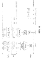
- FIG. 2 is a simplified block diagram of a transmitter system 210 (also known as the access network) and a receiver system 250 (also known as access terminal (AT) or user equipment (UE)) in a MIMO system 200.
- a transmitter system 210 also known as the access network
- a receiver system 250 also known as access terminal (AT) or user equipment (UE)
- traffic data for a number of data streams is provided from a data source 212 to a transmit (TX) data processor 214.
- TX transmit
- each data stream is transmitted over a respective transmit antenna.
- TX data processor 214 formats, codes, and interleaves the traffic data for each data stream based on a particular coding scheme selected for that data stream to provide coded data.
- the coded data for each data stream may be multiplexed with pilot data using OFDM techniques.
- the pilot data is typically a known data pattern that is processed in a known manner and may be used at the receiver system to estimate the channel response.
- the multiplexed pilot and coded data for each data stream is then modulated (i.e., symbol mapped) based on a particular modulation scheme (e.g., BPSK, QPSK, M-PSK, or M-QAM) selected for that data stream to provide modulation symbols.
- a particular modulation scheme e.g., BPSK, QPSK, M-PSK, or M-QAM
- the data rate, coding, and modulation for each data stream may be determined by instructions performed by processor 230.
- TX MIMO processor 220 may further process the modulation symbols (e.g., for OFDM).
- TX MIMO processor 220 then provides N T modulation symbol streams to N T transmitters (TMTR) 222a through 222t.
- TMTR TX MIMO processor 220 applies beamforming weights to the symbols of the data streams and to the antenna from which the symbol is being transmitted.
- Each transmitter 222 receives and processes a respective symbol stream to provide one or more analog signals, and further conditions (e.g., amplifies, filters, and upconverts) the analog signals to provide a modulated signal suitable for transmission over the MIMO channel.
- N T modulated signals from transmitters 222a through 222t are then transmitted from N T antennas 224a through 224t, respectively.
- the transmitted modulated signals are received by N R antennas 252a through 252r and the received signal from each antenna 252 is provided to a respective receiver (RCVR) 254a through 254r.
- Each receiver 254 conditions (e.g., filters, amplifies, and downconverts) a respective received signal, digitizes the conditioned signal to provide samples, and further processes the samples to provide a corresponding "received" symbol stream.
- An RX data processor 260 then receives and processes the N R received symbol streams from N R receivers 254 based on a particular receiver processing technique to provide N T "detected" symbol streams.
- the RX data processor 260 then demodulates, deinterleaves, and decodes each detected symbol stream to recover the traffic data for the data stream.
- the processing by RX data processor 260 is complementary to that performed by TX MIMO processor 220 and TX data processor 214 at transmitter system 210.
- a processor 270 periodically determines which pre-coding matrix to use (discussed below). Processor 270 formulates a reverse link message comprising a matrix index portion and a rank value portion.
- the reverse link message may comprise various types of information regarding the communication link and/or the received data stream.
- the reverse link message is then processed by a TX data processor 238, which also receives traffic data for a number of data streams from a data source 236, modulated by a modulator 280, conditioned by transmitters 254a through 254r, and transmitted back to transmitter system 210.
- the modulated signals from receiver system 250 are received by antennas 224, conditioned by receivers 222, demodulated by a demodulator 240, and processed by a RX data processor 242 to extract the reserve link message transmitted by the receiver system 250.
- Processor 230 determines which pre-coding matrix to use for determining the beamforming weights then processes the extracted message.
- FIG. 3 shows an alternative simplified functional block diagram of a communication device according to one embodiment of the invention.
- the communication device 300 in a wireless communication system can be utilized for realizing the UEs (or ATs) 116 and 122 in FIG. 1 or the base station (or AN) 100 in FIG. 1 , and the wireless communications system is preferably the LTE or NR system.
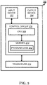
- the communication device 300 may include an input device 302, an output device 304, a control circuit 306, a central processing unit (CPU) 308, a memory 310, a program code 312, and a transceiver 314.
- the control circuit 306 executes the program code 312 in the memory 310 through the CPU 308, thereby controlling an operation of the communications device 300.
- the communications device 300 can receive signals input by a user through the input device 302, such as a keyboard or keypad, and can output images and sounds through the output device 304, such as a monitor or speakers.
- the transceiver 314 is used to receive and transmit wireless signals, delivering received signals to the control circuit 306, and outputting signals generated by the control circuit 306 wirelessly.
- the communication device 300 in a wireless communication system can also be utilized for realizing the AN 100 in FIG. 1 .
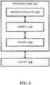
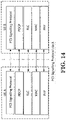
- FIG. 4 is a simplified block diagram of the program code 312 shown in FIG. 3 .
- the program code 312 includes an application layer 400, a Layer 3 portion 402, and a Layer 2 portion 404, and is coupled to a Layer 1 portion 406.
- the Layer 3 portion 402 generally performs radio resource control.
- the Layer 2 portion 404 generally performs link control.
- the Layer 1 portion 406 generally performs physical connections.
- 3GPP RAN2#104 meeting made the following agreements on NR eV2X sidelink communications as discussed in the 3GPP RAN2 #104 Chairman's note: Agreements on unicast 1: For AS-level information required to exchange among UEs via sidelink for SL unicast, RAN2 can consider the followings as a baseline and will check if the AS-level information can be agreed and the details after some progress in RAN2, SA2 and RAN1: - UE ID, UE capability, Radio/Bearer configuration, PHY information/configuration (e.g. HARQ, CSI), Resource information/configuration and QoS info 2: AS-level information for SL unicast can be exchanged between gNB and UE for RRC configuration.
- SA2 and RAN1 - UE ID, UE capability, Radio/Bearer configuration, PHY information/configuration (e.g. HARQ, CSI), Resource information/configuration and QoS info 2: AS-level information for SL unicast can be exchange
- RAN2 assumes that a UE can provide network with QoS related information and will check if the AS-level information can be agreed and the details after some progress in RAN2, SA2 and RAN1.
- AS-level information is exchanged via RRC signalling (e.g. PC5-RRC) among UEs via sidelink for SL unicast.
- New logical channel SCCH: SL Control Channel
- STCH SL Traffic Channel
- SCCH carriers PC5-RRC messages.
- RAN2 will consider both options during SI phase. Further discussion on the definition, procedure and information for each option is needed.
- - Option 1 AS layer connection establishment procedure by PC5-RRC is also needed.
- - Option 2 Upper layer connection establishment procedure is enough.
- RAN2 will study a kind of RRM or RLM based AS level link management. RAN2 will not consider a kind of PC5-RRC level keep alive message based management. Further discussion on possible detailed options is needed.
- 3GPP TR 23.786 introduced the following solutions for eV2X communications:
- Solution #11 Solution for unicast or multicast for eV2X communication over PC5 reference point
- L2 ID One of the essential identifiers for the unicast/multicast communication is the L2 ID.
- the destination L2 ID address space for one-to-one communication and one-to-many communications are separate with AS layer mechanism, i.e. MAC layer version number. This is done to avoid conflicts of the address used that may cause harm to one-to-one communications.
- V2X unicast should also use the separate L2 IDs than that for the broadcast and multicast.
- L2 ID For a UE that has both broadcast and unicast/multicast traffic, different L2 IDs should be used with corresponding formats.
- the source L2 ID will be used by peer UE as the destination L2 ID in unicast communication. Details of the related L2 ID management for unicast/multicast is described in following clauses.
- the UE may use distinct source L2 ID for different unicast one to one communication link e.g. when different unicast links are associated with different upper layer identifiers.
- the Destination L2 ID is decided by the UE based on a configured mapping between PSID/ITS-AID to the L2 ID. This suites for broadcast traffic, but does not work for unicast or multicast traffic. In unicast or multicast, destination L2 ID would not be decided based on PSID/ITS-AID.
- a V2X UE should be allowed to have multiple unicast connections or multicast groups supported simultaneously for a particular service (PSID/ITS-AID). Therefore, the destination L2 ID information in this case should come from the upper layer. This means that the interface between the V2X layer and upper layer needs to be enhanced to allow such information to be passed down together with the data packet.
- mid-ware layer within the UE has to translate the identifier used by the application layer, e.g. Station ID, to the V2X L2 ID. It means such mid-ware layer needs to maintain the mapping of application layer destination identifiers and L2 IDs. Since this mid-ware layer is out of scope of SA2, in the specification it can be noted as "upper layer” in general, and the assumption that this "upper layer” maintains the mapping and provides the L2 ID for unicast or multicast communication should be documented.
- V2X layer manages such unicast link/multicast group to L2 ID mapping.
- the unicast link/multicast group can be allocated with a flow identifier at the time of establishment.
- Corresponding connection profile information e.g. L2 IDs, transmission settings, QoS parameters, etc., could be associated with it.
- the upper layer only needs to use the flow identifier to indicate the destination and pass it down with the data packet.
- V2X layer will apply the associated profile information, including the L2 IDs, for the transmission. This would allow the reuse the Uu link handling mechanisms, e.g. similar to that of the QoS Flows, and be more extensible.
- the translation of the application layer identifiers, e.g. Station ID to this flow identifier has to be done by this mid-ware layer, i.e. the "upper layer".
- QoS can be support over the unicast and multicast communication as well.
- the QoS model for V2X communication is based on the per packet model, e.g. PPPP and PPPR.
- PPPP per packet model
- PPPR per packet model
- the unicast or multicast communication may need protection at link layer as well.
- the ProSe one-to-one communication supports secure L2 link establishment, as defined in TS 33.303 [11].
- each UE has the corresponding certificates for the security protection. Therefore, there may be a need to enhancement or adjust the existing L2 secure link establishment protocol in order to support the use of such security associations.
- TS 23.303 [8] has defined the procedures for the establishment and maintenance of secure L2 link over PC5, as in clause 5.4.5. These procedures can be enhanced and adapted for the V2X use, subject to the decisions above regarding signalling protocol choice, security handling, etc. Some addition considerations for the V2X for the link/group handling is required though.
- V2X communication not all UEs will be supporting or use unicast communication. In addition, not all services may be run over the same channel or RAT (e.g. LTE V2X vs. NR V2X).
- LTE V2X vs. NR V2X e.g. LTE V2X vs. NR V2X.
- there is no discovery channel like that of ProSe i.e. PC5-D
- there is no assumption on the configuration from network as that of Public Safety use Therefore, in order to support the link establishment, there is a need for service announcement in order to inform the peer of the existence of the UE and the capability of the UE for the un
- Such a service announcement should be made accessible to all the UEs that are interested in using the service. For example, such announcement could be either configured to send over a dedicate channel, similar to how WAVE Service Advertisement (WSA) is handled, or to be piggybacked on the periodical messages from the supporting UEs.
- WSA WAVE Service Advertisement
- keep-alive functionality is needed to detect that when the UEs are not in direct communication range, so that they can proceed with implicit layer 2 link release.
- Layer-2 link establishment procedure as defined in TS 23.303 [8] clause 5.4.5.2 can be reused for the eV2X unicast link establishment, with the following adaptations:
- the layer 2 link supports the non-IP traffic. No IP address negotiation and allocation procedure would be carried out.
- This procedure is used to update the peer in the unicast communication of the impending change of the identifiers used for this link. Due to the privacy requirements, in eV2X use, UE should frequently change its identifiers in order to avoiding being trackable by 3rd party. When the identifier change happens, all identifiers across all the layers, i.e. from application layer ID to L2 ID, need to be changed. This signaling is required before the identifier changes happen, to prevent service interruptions.
- the unicast link can reuse those to derive the security association for protecting the signalling or data of the unicast link.
- the application layer may use unicast or groupcast communication mechanism for different applications, e.g. platooning applications.
- the new service requirements were captured in TS 22.186 [4].
- the new performances KPIs were specified with the following parameters:
- the UE-PC5-AMBR is applied to all types of traffic and is used for the RAN for capping the UE PC5 transmission in the resources management.
- each of the unicast link could be treated as a bearer, and QoS flows could be associated with it. All the QoS characteristics defined in 5QI and the additional parameter of data rate could apply. In addition, the Minimum required communication range could be treated as an additional parameter specifically for PC5 use.
- each of the message may have different characteristics according to the application requirements.
- the 5QI should then be used in the similar manner as that of the PPPP/PPPR, i.e. to be tagged with each of the packet.
- 5QI is able to represent all the characteristics needed for the PC5 broadcast operation, e.g. latency, priority, reliability, etc.
- a group of V2X broadcast specific 5QIs i.e. VQIs
- VQIs could be defined for PC5 use.
- a set of new VQIs for V2X use will be defined in normative phase reflecting the service requirements documented in TS 22.186 [4].
- the PC5 QoS parameters and PC5 QoS rule are provisioned to the UE as part of service authorization parameters using the solution defined for Key Issue #5.
- the PC5 QoS rule is used to map the V2X services (e.g. PSID or ITS-AIDs of the V2X application) to the PC5 QoS flow.
- the PC5 QoS parameters retrieved by the PCF from the UDR are provided to the NG-RAN via AMF.
- the AMF stores such information as part of the UE context.
- Service request, Handover the provision of the PC5 QoS parameters via N2 will follow the description as per clause 6.6.2.
- NOTE 1 The UE-PC5-AMBR is provided by the UDM and the details will follow the description as per Solution #6.
- the PC5 QoS parameters provisioning to the UE and NG-RAN could be triggered by the UE Policy container included in the NAS message provided by the UE.
- the PCF sends to the AMF the updated PC5 QoS parameters for NG-RAN when needed.
- the PC5 QoS parameters are negotiated at the establishment of one-to-one communication procedure, so the one-to-one communication establishment procedure defined in TS 23.303 [8] is enhanced to support PC5 QoS parameters negotiation between two UEs. After the PC5 QoS parameters negotiation procedure, the same QoS is used in both directions.
- UEs engaged in one to one communication negotiate PC5 QoS parameters during the link establishment procedure.
- 3GPP R2-1900370 includes the following discussion: In some contributions [11] [12] [13], it was pointed out that there might be the need for the receiver UE to be informed of some receiver-side relevant parameters corresponding to the SLRB(s) configured at the transmitter UE side, so as for the receiver to get aligned with the transmitter and correctly receive the data sent from corresponding SLRB(s).
- Such receiver-side related SLRB configurations may include sequence number space and RLC modes if they are configurable [13], and the reason is easy to understand: if these parameters are configurable, when a UE receives the data corresponding to an LCID, the UE has to be informed of the specific values set for these parameters by the transmitter on the corresponding SL LCH (and corresponding SLRB), in order to process the reception of the data correctly.
- UEs with different RRC states/resource allocation modes may depend on different ways of signaling and procedures for their SL (pre-)configuration (i.e. dedicated signaling, system information and pre-configuration). Therefore, options with different signaling flows are given below.
- the gNB/ng-eNB may signal the configurations of the SLRB(s) associated with the PC5 QoS profile(s) reported; these SLRB configurations may include SLRB ID, PC5 QoS profile to SLRB mapping, SDAP/PDCP/RLC/LCH configurations, etc.
- Step 5 the UE in the AS establishes SLRB(s) associated with the QoS profile of the packet(s) as per gNB/nb-eNB configuration, and maps the
- this option is characterized by enabling the UE to directly "tell" the QoS parameters of available packets in RAN to the gNB/ng-eNB which thus no longer needs to rely on CN to get aware of the QoS profiles of the UE's traffic as in Uu.
- the gNB/ng-eNB configures SLRB depending on the PC5 QoS parameters of the actually packets available as reported by the UE, so it works in a UE-specific manner and is applied to RRC_CONNECTED UEs.
- Option 2 is to imitate the QoS flow based mechanism in NR Uu, because, as per Solution #19 in TR 23.786 [1], SA2 is also proposing, at least for QoS support SL unicast, to use the PC5 QoS flow based mechanism as follows [1]: 6.19.2.1.1 QoS parameters provision to UE and NG-RAN
- the PC5 QoS parameters and PC5 QoS rule are provisioned to the UE as part of service authorization parameters using the solution defined for Key Issue #5.
- the PC5 QoS rule is used to map the V2X services (e.g. PSID or ITS-AIDs of the V2X application) to the PC5 QoS flow.
- V2X services e.g. PSID or ITS-AIDs of the V2X application
- the PC5 QoS parameters are provisioned to the NG-RAN as part of The PC5 QoS parameters retrieved by the PCF from the UDR are provided to the NG-RAN via AMF.
- the AMF stores such information as part of the UE context.
- Service request, Handover the provision of the PC5 QoS parameters via N2 will follow the description as per clause 6.6.2.
- Step 0 the PC5 QoS parameters and PC5 QoS rules for each PC5 QoS flow are provisioned to the UE in advance by service authorization and provisioning procedure as above SA2 conclusions; similarly, PC5 QoS profiles for each QoS flows are also given to the eNB/ng-eNB in advance in a provisioning way.
- the UE can first derive the identifier of the associated PC5 QoS flow(s) based on the PC5 QoS rules configured in Step 0, and may then report these PC5 QFI(s) to the gNB/ng-eNB in Step 3.
- the gNB/ng-eNB side it can derive the QoS profile(s) of these reported PC5 QFI(s) based on the provisioning from 5GC in Step 0, and thus may signal the configurations of the SLRB(s) associated with the PC5 QFI(s) UE reported.
- Step 5 the UE in the AS establishes SLRB(s) associated with the PC5 QFI(s) of the packet(s) as per gNB/ng-eNB configuration, and maps available packet(s) to the SLRB(s) established.
- the biggest difference from Option 1 is that, with only QFI used as in NR Uu, the specific QoS parameters of each QoS flow may not be directly visible in the AS of the UE/RAN, so that the gNB/ng-eNB still needs to depend on the configuration from CN to know the specific QoS profile as in Uu (though the QoS profiles are provided in a provisioning way in advance)
- Option 3 is applied when one wants to apply NW-configured SLRB for RRC_IDLE/RRC_INACTIVE UEs as well.
- the gNB/ng-eNB uses V2X specific SIB to broadcast the SLRB configuration associated with each possible PC5 QoS profiles. Then, when packet(s) with specific PC5 QoS profile(s) arrive as in Step 1 and 2, the UE then establishes the SLRB(s) corresponding to these QoS profile(s) as per the cell-specific configurations broadcast in the SIB and maps the packet(s) to the SLRB(s) established.
- This option just turns the UE specific SLRB configurations, into cell-specific configurations. Though it is mainly designed for RRC_IDLE/RRC_INACTIVE UEs, it is technically usable for RRC_CONNECTED UEs as well.
- 3GPP TS 36.300 introduced the mapping between sidelink radio bearers and sidelink logical channels as follows:
- Layer 2 is split into the following sublayers: Medium Access Control (MAC), Radio Link Control (RLC) and Packet Data Convergence Protocol (PDCP).
- MAC Medium Access Control
- RLC Radio Link Control
- PDCP Packet Data Convergence Protocol
- the purpose of this procedure is to inform E-UTRAN that the UE is interested or no longer interested to receive sidelink communication or discovery, to receive V2X sidelink communication, as well as to request assignment or release of transmission resources for sidelink communication or discovery announcements or V2X sidelink communication or sidelink discovery gaps, to report parameters related to sidelink discovery from system information of inter-frequency/PLMN cells and to report the synchronization reference used by the UE for V2X sidelink communication.
- a UE capable of sidelink communication or V2X sidelink communication or sidelink discovery that is in RRC_CONNECTED may initiate the procedure to indicate it is (interested in) receiving sidelink communication or V2X sidelink communication or sidelink discovery in several cases including upon successful connection establishment, upon change of interest, upon change to a PCell broadcasting SystemInformationBlockType18 or SystemInformationBlockType19 or SystemInformationBlockType21 including sl-V2X-ConfigCommon.
- a UE capable of sidelink communication or V2X sidelink communication or sidelink discovery may initiate the procedure to request assignment of dedicated resources for the concerned sidelink communication transmission or discovery announcements or V2X sidelink communication transmission or to request sidelink discovery gaps for sidelink discovery transmission or sidelink discovery reception and a UE capable of inter-frequency/PLMN sidelink discovery parameter reporting may initiate the procedure to report parameters related to sidelink discovery from system information of inter-frequency/PLMN cells.
- the SidelinkUEInformation message is used for the indication of sidelink information to the eNB.
- SidelinkUEInformation message SidelinkUEInformation field descriptions carrierFreqCommTx Indicates the index of the frequency on which the UE is interested to transmit V2X sidelink communication.
- the value 1 corresponds to the frequency of first entry in v2x-InterFreqInfoList broadcast in SIB21
- the value 2 corresponds to the frequency of second entry in v2x-InterFreqInfoList broadcast in SIB21 and so on.
- the value 0 corresponds the PCell's frequency.
- commRxInterestedFreq Indicates the frequency on which the UE is interested to receive sidelink communication.
- commTxResourceReq Indicates the frequency on which the UE is interested to transmit non-relay related sidelink communication as well as the one-to-many sidelink communication transmission destination(s) for which the UE requests E-UTRAN to assign dedicated resources.
- reliabilitylnfoListSL Indicates the reliability(ies) (i.e., PPPRs [9]) associated with the reported traffic to be transmitted for V2X sidelink communication.
- v2x-CommRxInterestedFreqList Indicates the index(es) of the frequency(ies) on which the UE is interested to receive V2X sidelink communication.
- the value 1 corresponds to the frequency of first entry in v2x-InterFreqInfoList broadcast in SIB21
- the value 2 corresponds to the frequency of second entry in v2x-InterFreqInfoList broadcast in SIB21 and so on.
- the value 0 corresponds the PCell's frequency.
- v2x-DestinationInfoList Indicates the destination(s) for V2X sidelink communication.
- carrierFreqCommTx Indicates the index of the frequency on which the UE is interested to transmit V2X sidelink communication.
- the value 1 corresponds to the frequency of first entry in v2x-InterFreqInfoList broadcast in SIB21
- the value 2 corresponds to the frequency of second entry in v2x-InterFreqInfoList broadcast in SIB21 and so on.
- the value 0 corresponds the PCell's frequency.
- v2x-TypeTxSync Indicates the synchronization reference used by the UE.
- 3GPP TS 23.303 states:
- SL unicast For SL unicast, between the same UE pair, it is allowed to establish multiple links using same or different source IDs.
- a UE may establish multiple unicast links with a peer UE and use the same or different source Layer-2 IDs for these unicast links.
- Further updates of the identifier description may be required based on RAN WG feedback.
- L1 ID between the same UE pair for different links with different source L2 IDs the corresponding L1 IDs can also be different. However, in our view, this is not necessary and may cause issues for other procedures e.g. CSI report.
- the receiver UE will decode all packets from the peer UE even if those packets belong to different links.
- the channel condition is always the same. Therefore, it makes no sense to acquire CSI report for different links deduced from different source/destination L1 ID pairs between the same UE pair.
- a UE may establish multiple unicast links with a peer UE and use the same or different source Layer-2 IDs for these unicast links. Impacts to access stratum design are foreseen with respect to UE capability exchange, RLM/RLF procedure, and CSI report.
- Proposal 5 RAN2 investigates the impacts of allowing one UE to use multiple L2 source IDs for communication with the same peer UE. If needed, RAN2 sends LS to SA2 to clarify and feedback RAN2's view.
- 3GPP R2-1904094 states:
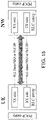
- the radio bearer configured with RLC AM is a bi-directional bearer, which include one PDCP entity, one RLC entity and one logical channel 3 .
- the RLC entity consists of a transmitting side and a receiving side.
- the RLC data PDU and the RLC status report (SR) are transmitted and received via the same RLC entity and the same logical channel (i.e. with same LCID).
- the modelling of such bi-directional radio bearer is illustrated in Figure.1 .
- each SLRB is unique within the scope of one Source Layer-2 ID (SRC L2 ID) and Destination Layer-2 ID (DST L2 ID) combination, no matter for unicast and groupcast in D2D communication or for broadcast in V2X SL communication. So it can be understood that each SL radio bearer is identified by the combination of ⁇ LCID, SRC L2 ID, DST L2 ID ⁇ of its associated SL LCH.
- SRC L2 ID Source Layer-2 ID
- DST L2 ID Destination Layer-2 ID
- the SLRB used for Tx to UE2 is identified by ⁇ UE1 ID, UE2 ID ⁇
- the SLRB used for Rx from UE2 is identified by ⁇ UE2 ID, UE1 ID ⁇ .
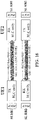
- an SL radio bearer, along with its associated PDCP/RLC entity 3 For simplicity, the PDCP duplication case is not considered throughout this paper and SL LCH in LTE SL unicast is uni-directional, either used for transmission only or reception only. The modelling of such uni-directional bearer is illustrated in the Figure.2 .
- each SL RB includes one PDCP entity, one uni-directional RLC entity and one SL logical channel.
- the principle of LTE SL that the LCID of the logical channel is unique within one Source Layer-2 ID/Destination Layer-2 ID combination is still kept, meaning that the SLRB/SL LCH/PDCP entity/RLC entity used for Tx and those for Rx are still distinguished by the associated ⁇ SRC L2 ID, DST L2 ID ⁇ pair.
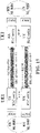
- Figure 3 shows the modelling of this option.
- the SR derived by an Rx RLC entity needs to be submitted to the corresponding Tx RLC entity for its transmission (e.g. at the UE2 side).
- the TX SLRB used to transmit the RLC data PDU (RLC SR) and the RX SLRB used to receive the corresponding RLC SR (RLC data PDU) when the involved SLRBs are configured as RLC AM.
- UE1 when UE1 initiates the unicast traffic configured with RLC AM to UE2, UE1 may need to establish both a Tx SLRB and an associated Rx SLRB with UE2:
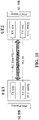
- each SLRB includes one PDCP entity, one bi-directional RLC entity and one SL logical channel.
- the LCID of the logical channel is no longer uniquely identified by ⁇ SRC L2 ID, DST L2 ID ⁇ combination which differentiates who is the source and who is the destination between the two UEs; instead, it should be unique within one unicast connection, e.g. no more differentiation on the order of UE1 ID and UE2 ID included in the ⁇ SRC L2 ID, DST L2 ID ⁇ combination.
- Figure 4 shows the modelling of this option.
- UE1 when UE1 initiates the unicast traffic configured with RLC AM to UE2, UE1 established one bi-directional SLRB which includes the Tx side and Rx side as in Uu with UE2, instead of two SLRBs respectively for Tx and Rx as in above Option 1:
- RAN2 intends to adopt the bi-directional SLRB modelling to support RLC AM in unicast, at least this issue should be first addressed: if one of the UEs has already established a bi-direction SLRB with RLC AM via NR-configuration/per-configuration, how to ensure its peer UE to be also (pre-)configured with RLC AM on the SLRB with the same LCID?
- a UE requests dedicated SLRB configurations from the gNB (e.g. when the UE is in RRC_CONNECTED), it may require the gNB of the UE to configure an SLRB by following the RLC mode of its peer UE, if the peer UE had already established the SLRB of the same LCID with RLC AM before and indicated this to that UE in SL.
- RAN2 is suggested to choose the SLRB modelling for SL RLC AM support by taking into account the above issues.
- Proposal 2 RAN2 to decide whether to adopt uni-directional or bi-directional SLRB modelling for RLC AM support in SL unicast, by taking into account their issues as shown in above Observations.
- 3GPP R2-1903227 states:
- the Rx UE can configure the (original) Tx UE with a reception configuration using a new configuration message. This leads to the flow shown in [ Figure , where UE1 is the initial Tx UE and UE2 is the initial Rx UE.
- Proposal 4 If the Rx UE needs to transmit data, it sends a new configuration message to the (previous) Tx UE with a reception configuration.
- the SLRB configuration may include SLRB ID(s), QoS flow-to-SLRB mapping, and AS (Access Stratum) configuration (e.g. PDCP (Packet Data Convergence Protocol)/RLC (Radio Link Control)/LCH (Logical Channel) configurations).
- PDCP Packet Data Convergence Protocol
- RLC Radio Link Control
- LCH Logical Channel
- the AS configuration could indicate, for example, t-Reordering, Reordering Window, Maximum_PDCP_SN, RLC mode (UM (Unacknowledged Mode) or AM (Acknowledged Mode)), AM_Window_Size, UM_Window_Size, identity of sidelink logical channel, and/or etc.
- the radio bearer configured with RLC AM is a bi-directional bearer, which includes one PDCP entity, one RLC entity and one logical channel.
- the RLC entity consists of a transmitting side and a receiving side.
- the RLC data PDU and the RLC status report are transmitted and received via the same RLC entity and the same logical channel (i.e. with same LCID).
- LTE SL only RLC UM is supported for the SLRB.
- each SLRB is unique within the scope of one Source Layer-2 ID (SRC L2 ID) and Destination Layer-2 ID (DST L2 ID) combination, no matter for unicast and groupcast in D2D communication or for broadcast in V2X SL communication.
- SRC L2 ID Source Layer-2 ID
- DST L2 ID Destination Layer-2 ID
- an SL radio bearer, along with its associated PDCP/RLC entity and SL LCH in LTE SL unicast is uni-directional, either used for transmission only or reception only.
- UE1 in RRC idle mode sends the SLRB configuration determined according to pre-configuration (or system information broadcasted by a base station) to UE2, which requires the gNB connecting to the UE2 to schedule the UE2 based on the SLRB configuration determined according to pre-configuration.
- the UE1 in RRC connected mode sends the SLRB configuration configured by gNB to UE2, which requires UE2 in RRC idle mode to use the SLRB configuration configured by gNB. Therefore, uni-directional SLRB for RLC AM (using separate sidelink logical channels) seems more proper for such scenarios. This concept may also be applied to other scenarios e.g. both UEs are in connected mode.
- the UE1 gets the SLRB configuration for Tx direction (based on gNB configuration or pre-configuration) and forward it to the UE2 -- i.e. it is not proper for the UE1 to start transmitting the packets (of a PC5 QoS flow) on the SLRB with RLC AM because the SLRB configuration for the counter (or opposite) direction to the UE1 has not been allocated and as a default the UE1 cannot receive the RLC status report indicating RLC ACK/NACK from the UE2.
- the UE1 needs to transmit traffic to the UE2, it can configure the UE2 with a SLRB configuration for reception using a new configuration message.
- the UE2 needs to request the gNB for the SLRB configuration for reception on the UE1.
- the UE2 cannot transmit the request for the SLRB configuration until a packet from the same QoS flow arrives at the UE2.
- the UE1 cannot transmit sidelink packets (of the PC5 QoS flow) on the SLRB until sidelink packets arrive at the UE2 that triggers the UE2 to send the SLRB configuration to the UE1. This situation would cause latency on sidelink transmission.
- the present invention provides a solution to solve the above issues of the background techniques.
- One concept of the invention is that the UE2 requests the gNB to configure the SLRB configuration for UE2-to-UE1 direction when it receives the SLRB configuration for UE1-to-UE2 direction from the UE1.
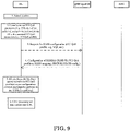
- the UE1 transmits a first SLRB configuration to the UE2, and the first SLRB configuration indicates a first SLRB ID for a SLRB with RLC AM.
- the UE2 transmit a request for SLRB configuration message to the gNB, and the gNB provides the NW-configured SLRB configuration to the UE2.
- the UE2 transmits a second SLRB configuration based on the NW-configured SLRB configuration to the UE1.
- SLRB ID there may be two options: (1) different SLRB IDs are used for separate directions and (2) same SLRB ID is used for separate directions.
- the UE2 may need to indicate the first SLRB ID in the request for SLRB configuration message; and if same SLRB ID is used, the first SLRB ID may not be needed in the request for SLRB configuration message, and the gNB may allocate a second SLRB ID for the SLRB in the NW-configured SLRB configuration.
- the first SLRB ID may be still included in the request for SLRB configuration message, and the gNB may allocate a second SLRB ID for the SLRB in the NW-configured SLRB configuration. Since the first SLRB ID and the second SLRB ID are associated with the same PC5 QoS flow, the first SLRB ID is paired with the second SLRB ID to support RLC AM for the same PC5 QoS flow. Possibly, the first SLRB ID and the second SLRB ID may be the same.
- UE2 may need to reply a complete message to UE2 in response to reception of the message including the first SLRB configuration from UE1.
- another potential timing for UE2 to request the second SLRB configuration from gNB is when successful transmission of the complete message has been confirmed by a lower layer (e.g. RLC layer, MAC layer or PHY layer).
- the transmission of the complete message can be confirmed by e.g. RLC acknowledgement or HARQ feedback acknowledgement associated with the transmission of the complete message.
- RLC acknowledgement e.g. RLC acknowledgement or HARQ feedback acknowledgement associated with the transmission of the complete message.
- both UE1 and UE2 are in RRC idle or inactive mode, the UE2 does not transmit the request for SLRB configuration message to the gNB when it receives the first SLRB configuration from the UE1.
- the UE1 cannot start to transmit the packets on the SLRB with RLC AM until the UE2 forwards the SLRB configuration for the counter (or opposite) direction to the UE1. Therefore, the UE2 could derive the second SLRB configuration according to system information broadcasted by the gNB or pre-configuration in the UE2 when/if it receives the first SLRB configuration from the UE1 and transmit the second SLRB configuration to the UE1.
- the LTE2 could derive the second SLRB configuration when/if a complete message in response to reception of a message including the first SLRB configuration is transmitted to the UE 1 successfully. Possibly, whether the transmission of the complete message has been transmitted successfully can be confirmed by reception of RLC acknowledgement or HARQ feedback acknowledgement associated with the transmission of the complete message.
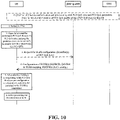
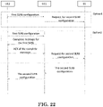
- This concept may also be applied to the case where UE1 is in connected mode and UE2 is in idle/inactive mode. This solution which is not covered by the claimed invention could be illustrated in FIG. 23 .
- the UE2 may need to transmit a request for the SLRB configuration to the gNB.
- the UE2 may transmit the second SLRB configuration based on the NW-configured SLRB configuration to the UE1.
- the UE1 replies a complete message to the UE2 in response to reception of a message including the second SLRB configuration.
- handling failure case for the reception of the SLRB configuration is discussed.
- the UE2 may need to inform this failure case to the gNB, and the gNB may release the NW-configured SLRB configuration. This case would cause signalling overhead.
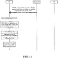
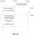
- Another signalling flow could be that the both UEs could first complete exchanging SLRB configurations (each SLRB configuration from each UE could be derived from system information or pre-configuration) with each other, and the UE in RRC connected mode then transmits a message used to request configuration related to sidelink transmissions on the unicast link (including e.g. mapping of QoS flow ID-to-SLRB ID, mapping of SLRB ID-to-LCG and/or etc., where the SLRB ID is assigned by UE, and an identity of the LCG is assigned by gNB).
- the message used to request the configuration related to sidelink transmissions on the unicast link could include e.g. SLRB ID, PC5 QoS flow ID and/or etc.
- the UE1 transmits a first SLRB configuration to the UE2, and the first SLRB configuration indicates a first SLRB ID for a SLRB with RLC AM.
- the UE2 transmits a complete message to the UE1.
- the UE2 transmits a second SLRB configuration to the UE1, and the second SLRB configuration indicates a second SLRB ID (or the first SLRB ID) for the SLRB with RLC AM.
- the UE1 transmit a complete message to the UE2.
- the UE2 Upon reception of the complete message, the UE2 transmits a message used to request configuration related to sidelink transmissions on the unicast link to the gNB, and then the gNB provides the configuration related to sidelink transmissions on the unicast link to the UE1.
- This solution which is not covered by the claimed invention could be illustrated in FIG. 24 .
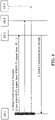
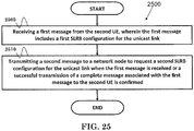
- FIG. 25 is a flow chart 2500 according to one exemplary embodiment of the claimed invention from the perspective of a first UE to request SLRB configuration for a unicast link with a second UE.
- the first UE receives a first message from the second UE, wherein the first message includes a first SLRB configuration for the unicast link.
- the first UE transmits a second message to a network node to request a second SLRB configuration for the unicast link when the first message is received or a successful transmission of a complete message associated with the first message to the second UE is confirmed.
- the first UE could receive a third message from the network node, wherein the third message includes the second SLRB configuration.
- the first UE could also transmit a fourth message to the second UE, wherein the fourth message includes the second SLRB configuration.
- the first message could include an identity of a PC5 QoS flow for the unicast link.
- the second message could include an identity of a PC5 QoS flow.
- the first SLRB configuration may be applied for receiving packets from the second UE, and the second SLRB configuration may be applied for transmitting packets to the second UE.
- the first message could be a PC5 RRC message.
- the fourth message could be a PC5 RRC message.
- the first UE could be in RRC_CONNECTED.
- the network node could be a base station (e.g., a gNB).
- the device 300 includes a program code 312 stored in the memory 310.
- the CPU 308 executes program code 312 to enable the first UE (i) to receive a first message from a second UE , wherein the first message includes a first SLRB configuration for the unicast link, and (ii) to transmit a second message to a network node to request a second SLRB configuration for the unicast link when the first message is received or a successful transmission of a complete message associated with the first message to the second UE is confirmed.
- the CPU 308 executes the program code 312 to perform all of the above-described actions and steps or others described herein.
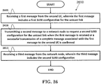
- FIG. 26 is a flow chart 2600 according to one preferred embodiment of the claimed invention from the perspective of a first UE to request SLRB configuration for a unicast link with a second UE.
- the first UE receives a first message from the second UE, wherein the first message includes a first SLRB configuration for the unicast link.
- the first UE transmits a second message to a network node to request a second SLRB configuration for the unicast link when the first message is received or a successful transmission of a complete message associated with the first message to the second UE is confirmed.
- the first UE receives a third message from the network node, wherein the third message includes the second SLRB configuration.
- the first UE could transmit a fourth message to the second UE, wherein the fourth message includes the second SLRB configuration.
- the first message may include an identity of a PC5 QoS flow for the unicast link.
- the second message may include the identity of the PC5 QoS flow.
- the third message may include the identity of the PC5 QoS flow.
- the first message may include an identity of a first SLRB associated with the first SLRB configuration.
- the second message may include an identity of a second SLRB associated with the second SLRB configuration.
- the identity of the second SLRB may be assigned by the first UE.
- the identity of the second SLRB may be equal to the identity of the first SLRB.
- the second message may not include an identity of a second SLRB associated with the second SLRB configuration.
- the identity of the second SLRB may be assigned by the network node.
- the third message may include the identity of the second SLRB associated with the second SLRB configuration.
- the fourth message may include information to indicate an association between the first SLRB configuration and the second SLRB configuration.
- the first SLRB configuration may be applied for receiving packets from the second UE, and the second SLRB configuration may be applied for transmitting packets to the second UE.
- the network node could be a base station (e.g., a gNB).
- the first message and/or the fourth message could be a PC5 RRC message.
- the second message could be a RRC message including UE assistance information.
- the third message could be a RRC reconfiguration message.
- the first UE could be in RRC_CONNECTED.
- the second UE could be in RRC_CONNECTED, RRC IDLE, or RRC INACTIVE.
- the first SLRB and/or the second SLRB could be associated with the identity of the PC5 QoS flow.
- the complete message could be transmitted by the first UE to the second UE in response to reception of the first message.
- the successful transmission of the complete message associated with the first message to the second UE could be confirmed based on a RLC acknowledgement or a HARQ feedback acknowledgement associated with the complete message.
- the device 300 includes a program code 312 stored in the memory 310.
- the CPU 308 executes program code 312 to enable the first UE (i) to receive a first message from a second UE, wherein the first message includes a first SLRB configuration for the unicast link, (ii) to transmit a second message to a network node to request a second SLRB configuration for the unicast link when the first message is received or a successful transmission of a complete message associated with the first message to the second UE is confirmed, and (iii) to receive a third message from the network node, wherein the third message includes the second SLRB configuration.
- the CPU 308 can execute the program code 312 to perform all of the above-described actions and steps or others described herein.
Claims (11)
- Verfahren für eine erste Teilnehmerausrüstung, im Folgenden auch als UE bezeichnet, um eine Sidelink-Funkträger-, im Folgenden auch als SLRB bezeichnet, Konfiguration für eine Unicast-Verbindung mit einer zweiten UE anzufordern, umfassend:Empfangen einer ersten Nachricht von der zweiten UE, wobei die erste Nachricht eine erste SLRB-Konfiguration für die Unicast-Verbindung umfasst (2505); undSenden einer zweiten Nachricht an einen Netzwerkknoten, um eine zweite SLRB-Konfiguration für die Unicast-Verbindung anzufordern, wenn die erste Nachricht empfangen ist oder eine erfolgreiche Übertragung einer vollständigen Nachricht, die mit der ersten Nachricht verknüpft ist, an die zweite UE bestätigt ist (2510).
- Verfahren gemäß Anspruch 1, weiter umfassend:
Empfangen einer dritten Nachricht von dem Netzwerkknoten, wobei die dritte Nachricht die zweite SLRB-Konfiguration umfasst. - Verfahren gemäß Anspruch 2, weiter umfassend:
Senden einer vierten Nachricht an die zweite UE, wobei die vierte Nachricht die zweite SLRB-Konfiguration umfasst. - Verfahren gemäß einem der Ansprüche 1 bis 3, wobei die erste Nachricht eine Identität eines PC5-Quality-of-Service-, im Folgenden auch als QoS bezeichnet, Flusses für die Unicast-Verbindung umfasst.
- Verfahren gemäß einem der Ansprüche 1 bis 4, wobei die zweite Nachricht eine Identität eines PC5-QoS-Flusses umfasst.
- Verfahren gemäß einem der Ansprüche 1 bis 5, wobei die erste SLRB-Konfiguration zum Empfangen von Paketen von der zweiten UE angewendet wird, und die zweite SLRB-Konfiguration zum Senden von Paketen an die zweite UE angewendet wird.
- Verfahren gemäß einem der Ansprüche 1 bis 6, wobei die erste Nachricht eine PC5-Funkressourcensteuerung-, im Folgenden auch als RRC bezeichnet, Nachricht ist.
- Verfahren gemäß Anspruch 3 oder einer Kombination eines der Ansprüche 4 bis 7 mit Anspruch 3, wobei die vierte Nachricht eine PC5-RRC-Nachricht ist.
- Verfahren gemäß einem der Ansprüche 1 bis 8, wobei sich die erste UE in RRC_CONNECTED befindet.
- Verfahren gemäß einem der Ansprüche 1 bis 9, wobei der Netzwerkknoten eine Basisstation ist.
- Erste Teilnehmerausrüstung, im Folgenden auch als UE bezeichnet, um eine Sidelink-Funkträger-, im Folgenden auch als SLRB bezeichnet, Konfiguration für eine Unicast-Verbindung mit einer zweiten UE anzufordern, aufweisend:eine Steuerungsschaltung (306);einen Prozessor (308), der in der Steuerungsschaltung (306) installiert ist; undeinen Speicher (310), der in der Steuerungsschaltung (306) installiert und betriebsfähig mit dem Prozessor (308) verbunden ist;dadurch gekennzeichnet, dass der Prozessor (308) eingerichtet ist, einen Programm-Code (312), der in dem Speicher (310) gespeichert ist, auszuführen, um die in einem der vorstehenden Ansprüche definierten Verfahrensschritte auszuführen.
Applications Claiming Priority (1)
| Application Number | Priority Date | Filing Date | Title |
|---|---|---|---|
| US201962842179P | 2019-05-02 | 2019-05-02 |
Publications (2)
| Publication Number | Publication Date |
|---|---|
| EP3742832A1 EP3742832A1 (de) | 2020-11-25 |
| EP3742832B1 true EP3742832B1 (de) | 2022-11-02 |
Family
ID=70294981
Family Applications (1)
| Application Number | Title | Priority Date | Filing Date |
|---|---|---|---|
| EP20170006.9A Active EP3742832B1 (de) | 2019-05-02 | 2020-04-17 | Verfahren und vorrichtung zur anforderung einer sidelink-funkträger(slrb)-konfiguration einer unicast-übertragung in einem drahtlosen kommunikationssystem |
Country Status (7)
| Country | Link |
|---|---|
| US (2) | US10904787B2 (de) |
| EP (1) | EP3742832B1 (de) |
| JP (1) | JP6902651B2 (de) |
| KR (1) | KR102328223B1 (de) |
| CN (1) | CN111885734B (de) |
| ES (1) | ES2934143T3 (de) |
| TW (1) | TWI742619B (de) |
Families Citing this family (8)
| Publication number | Priority date | Publication date | Assignee | Title |
|---|---|---|---|---|
| US11405895B2 (en) * | 2018-02-11 | 2022-08-02 | Lg Electronics Inc. | Method and apparatus for configuring feedback signal for sidelink communication in wireless communication system |
| EP3628116B1 (de) * | 2018-08-03 | 2021-12-29 | Telefonaktiebolaget LM Ericsson (publ) | Verfahren, benutzergerät und basisstation zur identifizierung von sidelinks |
| KR20200094343A (ko) | 2019-01-30 | 2020-08-07 | 삼성전자주식회사 | 무선 통신 시스템에서 직접 통신 베어러의 서비스 품질을 관리 및 설정하는 장치 및 방법 |
| CN114223225B (zh) * | 2019-08-15 | 2023-07-14 | 中兴通讯股份有限公司 | 对等终端之间的侧链路能力信息传输和安全 |
| EP3841827B1 (de) * | 2019-11-04 | 2024-04-17 | Apple Inc. | Bidirektionale sidelink-funkverbindungssteuerungsträger |
| KR20210056067A (ko) * | 2019-11-08 | 2021-05-18 | 삼성전자주식회사 | 무선 통신 시스템에서 사이드링크 라디오 베어러 구성 정보를 처리하기 위한 장치 및 방법 |
| US11812481B2 (en) * | 2020-03-06 | 2023-11-07 | Qualcomm Incorporated | Layer 2 relay unicast link setup |
| CN116582948A (zh) * | 2022-01-30 | 2023-08-11 | 华为技术有限公司 | 侧行链路通信方法、设备、存储介质和计算机程序产品 |
Citations (1)
| Publication number | Priority date | Publication date | Assignee | Title |
|---|---|---|---|---|
| WO2020103811A1 (en) * | 2018-11-19 | 2020-05-28 | Huawei Technologies Co., Ltd. | System and method for supporting sidelink radio bearers |
Family Cites Families (30)
| Publication number | Priority date | Publication date | Assignee | Title |
|---|---|---|---|---|
| US8331399B2 (en) * | 2007-05-07 | 2012-12-11 | Qualcomm Incorporated | Re-using sequence number by multiple protocols for wireless communication |
| CN104936292B (zh) * | 2014-03-18 | 2019-02-05 | 电信科学技术研究院 | 用于设备到设备信号传输的资源分配方法和装置 |
| US10194483B2 (en) * | 2014-04-24 | 2019-01-29 | Lg Electronics Inc. | Method for releasing a sidelink radio bearer for D2D communication system and device therefor |
| US10292192B2 (en) * | 2014-05-06 | 2019-05-14 | Lg Electronics Inc. | Method for processing received RLC PDUs for D2D communication system and device therefor |
| EP3923614B1 (de) * | 2014-11-10 | 2024-01-03 | LG Electronics Inc. | Vorrichtung und verfahren um eine verschlüsselungsanzeige zu übertragen |
| KR102410216B1 (ko) * | 2014-12-18 | 2022-06-17 | 엘지전자 주식회사 | 무선 통신 시스템에서 pdcp 리오더링 타이머를 재설정하는 방법 및 그 장치 |
| EP3051736B1 (de) * | 2015-01-30 | 2020-04-29 | Panasonic Intellectual Property Corporation of America | Priorisierung im Verfahren zur logischen Kanalpriorisierung für logische Sidelink-Kanäle in ProSe-Direktkommunikationen |
| US20180132161A1 (en) * | 2015-05-15 | 2018-05-10 | Lg Electronics Inc. | Method for transmitting discovery signal for establishing d2d link with relay ue in wireless communication system and apparatus therefor |
| CN107852759B (zh) | 2015-08-07 | 2020-02-14 | 华为技术有限公司 | 连接控制装置及方法 |
| EP3148285B1 (de) * | 2015-09-25 | 2019-04-17 | Panasonic Intellectual Property Corporation of America | Verbesserte funkträgerzuordnung für endgerät zu netzwerk 3gpp proximity services relais mittels signalisierung der verbundene priorität |
| US10257677B2 (en) * | 2015-10-16 | 2019-04-09 | Qualcomm Incorporated | System and method for device-to-device communication with evolved machine type communication |
| KR102215258B1 (ko) * | 2016-02-05 | 2021-02-15 | 후아웨이 테크놀러지 컴퍼니 리미티드 | 통신 리소스 할당을 위한 방법 및 디바이스, 단말 디바이스, 기지국, 및 통신 시스템 |
| CN108370592B (zh) | 2016-03-30 | 2021-01-29 | 华为技术有限公司 | 承载切换方法及基站设备、网络节点 |
| WO2017166115A1 (zh) * | 2016-03-30 | 2017-10-05 | 广东欧珀移动通信有限公司 | 数据传输的方法、基站及终端设备 |
| CN109479302B (zh) * | 2016-07-07 | 2020-09-29 | 松下电器(美国)知识产权公司 | 用于v2x发送的改进的半持续资源分配行为 |
| EP3273634A1 (de) * | 2016-07-18 | 2018-01-24 | Panasonic Intellectual Property Corporation of America | Verbesserte unterstützung der dienstqualität für v2x-übertragungen |
| CN110447293B (zh) * | 2017-03-24 | 2023-04-25 | 瑞典爱立信有限公司 | 为侧链路通信和相关无线终端提供调度的方法 |
| US10405231B2 (en) * | 2017-04-24 | 2019-09-03 | Motorola Mobility Llc | Switching between packet duplication operating modes |
| EP3399724B1 (de) * | 2017-05-05 | 2022-10-05 | ASUSTek Computer Inc. | Verfahren und vorrichtung zur übertragung von datenduplizierung in einem drahtloskommunikationssystem |
| CN108990125B (zh) * | 2017-06-01 | 2020-12-22 | 华为技术有限公司 | 数据传输的方法、终端设备和网络设备 |
| EP3860239A1 (de) * | 2017-06-15 | 2021-08-04 | BlackBerry Limited | Konfigurieren von sidelink-kommunikationen |
| WO2019061182A1 (en) * | 2017-09-28 | 2019-04-04 | Zte Corporation | SYSTEMS AND METHODS FOR EXECUTING CARRIER AGGREGATION IN LATERAL BINDING COMMUNICATIONS |
| US10827380B2 (en) * | 2018-01-30 | 2020-11-03 | Huawei Technologies Co., Ltd. | System and method for supporting URLLC in advanced V2X communications |
| TWI712292B (zh) * | 2018-09-10 | 2020-12-01 | 華碩電腦股份有限公司 | 無線通訊系統中用於改進側鏈路複製接收的初始化的方法和設備 |
| CN112970275A (zh) * | 2018-11-02 | 2021-06-15 | 鸿颖创新有限公司 | 下一代无线网络侧链路测量报告的方法和用户设备 |
| KR102281974B1 (ko) * | 2019-01-11 | 2021-07-27 | 아서스테크 컴퓨터 인코포레이션 | 무선 통신 시스템에서 사이드링크 자원 할당 모드 구성을 위한 방법 및 장치 |
| CN111698723B (zh) * | 2019-03-14 | 2023-03-14 | 华硕电脑股份有限公司 | 无线通信系统中侧链路逻辑信道建立的方法和设备 |
| US11464066B2 (en) * | 2019-04-05 | 2022-10-04 | Qualcomm Incorporated | Establishing radio bearers on millimeter wave frequencies for device-to-device communications |
| US11540106B2 (en) * | 2019-04-05 | 2022-12-27 | Qualcomm Incorporated | Beam sweeping on millimeter wave frequencies for device-to-device communications |
| KR20210056067A (ko) * | 2019-11-08 | 2021-05-18 | 삼성전자주식회사 | 무선 통신 시스템에서 사이드링크 라디오 베어러 구성 정보를 처리하기 위한 장치 및 방법 |
-
2020
- 2020-04-17 ES ES20170006T patent/ES2934143T3/es active Active
- 2020-04-17 EP EP20170006.9A patent/EP3742832B1/de active Active
- 2020-04-17 US US16/851,916 patent/US10904787B2/en active Active
- 2020-04-17 JP JP2020073770A patent/JP6902651B2/ja active Active
- 2020-04-17 CN CN202010304418.7A patent/CN111885734B/zh active Active
- 2020-04-17 KR KR1020200046939A patent/KR102328223B1/ko active IP Right Grant
- 2020-04-17 TW TW109113108A patent/TWI742619B/zh active
- 2020-12-17 US US17/125,988 patent/US11589254B2/en active Active
Patent Citations (1)
| Publication number | Priority date | Publication date | Assignee | Title |
|---|---|---|---|---|
| WO2020103811A1 (en) * | 2018-11-19 | 2020-05-28 | Huawei Technologies Co., Ltd. | System and method for supporting sidelink radio bearers |
Also Published As
| Publication number | Publication date |
|---|---|
| KR102328223B1 (ko) | 2021-11-18 |
| US10904787B2 (en) | 2021-01-26 |
| EP3742832A1 (de) | 2020-11-25 |
| US11589254B2 (en) | 2023-02-21 |
| CN111885734B (zh) | 2021-08-24 |
| US20210105653A1 (en) | 2021-04-08 |
| JP6902651B2 (ja) | 2021-07-14 |
| JP2020184752A (ja) | 2020-11-12 |
| ES2934143T3 (es) | 2023-02-17 |
| KR20200128354A (ko) | 2020-11-12 |
| TW202044902A (zh) | 2020-12-01 |
| US20200351699A1 (en) | 2020-11-05 |
| CN111885734A (zh) | 2020-11-03 |
| TWI742619B (zh) | 2021-10-11 |
Similar Documents
| Publication | Publication Date | Title |
|---|---|---|
| US11357064B2 (en) | Method and apparatus for supporting one-to-one sidelink communication in a wireless communication system | |
| EP3742832B1 (de) | Verfahren und vorrichtung zur anforderung einer sidelink-funkträger(slrb)-konfiguration einer unicast-übertragung in einem drahtlosen kommunikationssystem | |
| EP3709760B1 (de) | Verfahren und vorrichtungen zur einrichtung eines logischen sidelink-kanals in einem drahtlosen kommunikationssystem | |
| EP3758433B1 (de) | Verfahren und vorrichtung zur konfiguration der sidelink-kommunikation in einem drahtloskommunikationssystem | |
| EP3817447B1 (de) | Verfahren und vorrichtung zur unterstützung des flusses von qos (dienstqualität) zu remapping von drb (datenfunkträger) für sidelink-kommunikation in einem drahtloskommunikationssystem | |
| EP3723442B1 (de) | Verfahren und vorrichtungen zur handhabung des wechselns von sidelink-identifikatoren in einem drahtloskommunikationssystem | |
| EP3787368B1 (de) | Verfahren und vorrichtung zur header-komprimierungskonfiguration für sidelink-funkträger in einem drahtlosen kommunikationssystem | |
| EP3849237B1 (de) | Verfahren und vorrichtung zur beantragung von ressourcen zur sidelink-übertragung in einem drahtloskommunikationssystem | |
| KR20210016270A (ko) | 무선 통신 시스템에서 사이드링크 라디오 베어러를 해제하기 위한 방법 및 장치 | |
| KR20210104566A (ko) | 무선 통신 시스템에서 사이드링크 통신에 대한 무효 rrc 재구성 메시지를 핸들링하기 위한 방법 및 장치 | |
| CN114390532A (zh) | 无线通信系统中用户设备到网络中继的适配层配置的方法和设备 |
Legal Events
| Date | Code | Title | Description |
|---|---|---|---|
| PUAI | Public reference made under article 153(3) epc to a published international application that has entered the european phase |
Free format text: ORIGINAL CODE: 0009012 |
|
| STAA | Information on the status of an ep patent application or granted ep patent |
Free format text: STATUS: THE APPLICATION HAS BEEN PUBLISHED |
|
| AK | Designated contracting states |
Kind code of ref document: A1 Designated state(s): AL AT BE BG CH CY CZ DE DK EE ES FI FR GB GR HR HU IE IS IT LI LT LU LV MC MK MT NL NO PL PT RO RS SE SI SK SM TR |
|
| AX | Request for extension of the european patent |
Extension state: BA ME |
|
| STAA | Information on the status of an ep patent application or granted ep patent |
Free format text: STATUS: REQUEST FOR EXAMINATION WAS MADE |
|
| 17P | Request for examination filed |
Effective date: 20210121 |
|
| RBV | Designated contracting states (corrected) |
Designated state(s): AL AT BE BG CH CY CZ DE DK EE ES FI FR GB GR HR HU IE IS IT LI LT LU LV MC MK MT NL NO PL PT RO RS SE SI SK SM TR |
|
| STAA | Information on the status of an ep patent application or granted ep patent |
Free format text: STATUS: EXAMINATION IS IN PROGRESS |
|
| 17Q | First examination report despatched |
Effective date: 20210318 |
|
| GRAP | Despatch of communication of intention to grant a patent |
Free format text: ORIGINAL CODE: EPIDOSNIGR1 |
|
| STAA | Information on the status of an ep patent application or granted ep patent |
Free format text: STATUS: GRANT OF PATENT IS INTENDED |
|
| INTG | Intention to grant announced |
Effective date: 20220823 |
|
| GRAS | Grant fee paid |
Free format text: ORIGINAL CODE: EPIDOSNIGR3 |
|
| GRAA | (expected) grant |
Free format text: ORIGINAL CODE: 0009210 |
|
| STAA | Information on the status of an ep patent application or granted ep patent |
Free format text: STATUS: THE PATENT HAS BEEN GRANTED |
|
| AK | Designated contracting states |
Kind code of ref document: B1 Designated state(s): AL AT BE BG CH CY CZ DE DK EE ES FI FR GB GR HR HU IE IS IT LI LT LU LV MC MK MT NL NO PL PT RO RS SE SI SK SM TR |
|
| RAP3 | Party data changed (applicant data changed or rights of an application transferred) |
Owner name: ASUSTEK COMPUTER INC. |
|
| REG | Reference to a national code |
Ref country code: GB Ref legal event code: FG4D |
|
| RIN1 | Information on inventor provided before grant (corrected) |
Inventor name: KUO, RICHARD LEE-CHEE Inventor name: PAN, LI-TE |
|
| REG | Reference to a national code |
Ref country code: CH Ref legal event code: EP Ref country code: AT Ref legal event code: REF Ref document number: 1529707 Country of ref document: AT Kind code of ref document: T Effective date: 20221115 |
|
| REG | Reference to a national code |
Ref country code: DE Ref legal event code: R096 Ref document number: 602020005968 Country of ref document: DE |
|
| REG | Reference to a national code |
Ref country code: IE Ref legal event code: FG4D |
|
| REG | Reference to a national code |
Ref country code: NL Ref legal event code: FP |
|
| REG | Reference to a national code |
Ref country code: ES Ref legal event code: FG2A Ref document number: 2934143 Country of ref document: ES Kind code of ref document: T3 Effective date: 20230217 |
|
| REG | Reference to a national code |
Ref country code: LT Ref legal event code: MG9D |
|
| REG | Reference to a national code |
Ref country code: AT Ref legal event code: MK05 Ref document number: 1529707 Country of ref document: AT Kind code of ref document: T Effective date: 20221102 |
|
| PG25 | Lapsed in a contracting state [announced via postgrant information from national office to epo] |
Ref country code: SE Free format text: LAPSE BECAUSE OF FAILURE TO SUBMIT A TRANSLATION OF THE DESCRIPTION OR TO PAY THE FEE WITHIN THE PRESCRIBED TIME-LIMIT Effective date: 20221102 Ref country code: PT Free format text: LAPSE BECAUSE OF FAILURE TO SUBMIT A TRANSLATION OF THE DESCRIPTION OR TO PAY THE FEE WITHIN THE PRESCRIBED TIME-LIMIT Effective date: 20230302 Ref country code: NO Free format text: LAPSE BECAUSE OF FAILURE TO SUBMIT A TRANSLATION OF THE DESCRIPTION OR TO PAY THE FEE WITHIN THE PRESCRIBED TIME-LIMIT Effective date: 20230202 Ref country code: LT Free format text: LAPSE BECAUSE OF FAILURE TO SUBMIT A TRANSLATION OF THE DESCRIPTION OR TO PAY THE FEE WITHIN THE PRESCRIBED TIME-LIMIT Effective date: 20221102 Ref country code: FI Free format text: LAPSE BECAUSE OF FAILURE TO SUBMIT A TRANSLATION OF THE DESCRIPTION OR TO PAY THE FEE WITHIN THE PRESCRIBED TIME-LIMIT Effective date: 20221102 Ref country code: AT Free format text: LAPSE BECAUSE OF FAILURE TO SUBMIT A TRANSLATION OF THE DESCRIPTION OR TO PAY THE FEE WITHIN THE PRESCRIBED TIME-LIMIT Effective date: 20221102 |
|
| PGFP | Annual fee paid to national office [announced via postgrant information from national office to epo] |
Ref country code: FR Payment date: 20230201 Year of fee payment: 4 |
|
| PG25 | Lapsed in a contracting state [announced via postgrant information from national office to epo] |
Ref country code: RS Free format text: LAPSE BECAUSE OF FAILURE TO SUBMIT A TRANSLATION OF THE DESCRIPTION OR TO PAY THE FEE WITHIN THE PRESCRIBED TIME-LIMIT Effective date: 20221102 Ref country code: PL Free format text: LAPSE BECAUSE OF FAILURE TO SUBMIT A TRANSLATION OF THE DESCRIPTION OR TO PAY THE FEE WITHIN THE PRESCRIBED TIME-LIMIT Effective date: 20221102 Ref country code: LV Free format text: LAPSE BECAUSE OF FAILURE TO SUBMIT A TRANSLATION OF THE DESCRIPTION OR TO PAY THE FEE WITHIN THE PRESCRIBED TIME-LIMIT Effective date: 20221102 Ref country code: IS Free format text: LAPSE BECAUSE OF FAILURE TO SUBMIT A TRANSLATION OF THE DESCRIPTION OR TO PAY THE FEE WITHIN THE PRESCRIBED TIME-LIMIT Effective date: 20230302 Ref country code: HR Free format text: LAPSE BECAUSE OF FAILURE TO SUBMIT A TRANSLATION OF THE DESCRIPTION OR TO PAY THE FEE WITHIN THE PRESCRIBED TIME-LIMIT Effective date: 20221102 Ref country code: GR Free format text: LAPSE BECAUSE OF FAILURE TO SUBMIT A TRANSLATION OF THE DESCRIPTION OR TO PAY THE FEE WITHIN THE PRESCRIBED TIME-LIMIT Effective date: 20230203 |
|
| P01 | Opt-out of the competence of the unified patent court (upc) registered |
Effective date: 20230428 |
|
| PGFP | Annual fee paid to national office [announced via postgrant information from national office to epo] |
Ref country code: NL Payment date: 20230116 Year of fee payment: 4 |
|
| PG25 | Lapsed in a contracting state [announced via postgrant information from national office to epo] |
Ref country code: SM Free format text: LAPSE BECAUSE OF FAILURE TO SUBMIT A TRANSLATION OF THE DESCRIPTION OR TO PAY THE FEE WITHIN THE PRESCRIBED TIME-LIMIT Effective date: 20221102 Ref country code: RO Free format text: LAPSE BECAUSE OF FAILURE TO SUBMIT A TRANSLATION OF THE DESCRIPTION OR TO PAY THE FEE WITHIN THE PRESCRIBED TIME-LIMIT Effective date: 20221102 Ref country code: EE Free format text: LAPSE BECAUSE OF FAILURE TO SUBMIT A TRANSLATION OF THE DESCRIPTION OR TO PAY THE FEE WITHIN THE PRESCRIBED TIME-LIMIT Effective date: 20221102 Ref country code: DK Free format text: LAPSE BECAUSE OF FAILURE TO SUBMIT A TRANSLATION OF THE DESCRIPTION OR TO PAY THE FEE WITHIN THE PRESCRIBED TIME-LIMIT Effective date: 20221102 Ref country code: CZ Free format text: LAPSE BECAUSE OF FAILURE TO SUBMIT A TRANSLATION OF THE DESCRIPTION OR TO PAY THE FEE WITHIN THE PRESCRIBED TIME-LIMIT Effective date: 20221102 |
|
| PGFP | Annual fee paid to national office [announced via postgrant information from national office to epo] |
Ref country code: IT Payment date: 20230501 Year of fee payment: 4 Ref country code: ES Payment date: 20230505 Year of fee payment: 4 Ref country code: DE Payment date: 20230119 Year of fee payment: 4 |
|
| REG | Reference to a national code |
Ref country code: DE Ref legal event code: R097 Ref document number: 602020005968 Country of ref document: DE |
|
| PG25 | Lapsed in a contracting state [announced via postgrant information from national office to epo] |
Ref country code: SK Free format text: LAPSE BECAUSE OF FAILURE TO SUBMIT A TRANSLATION OF THE DESCRIPTION OR TO PAY THE FEE WITHIN THE PRESCRIBED TIME-LIMIT Effective date: 20221102 Ref country code: AL Free format text: LAPSE BECAUSE OF FAILURE TO SUBMIT A TRANSLATION OF THE DESCRIPTION OR TO PAY THE FEE WITHIN THE PRESCRIBED TIME-LIMIT Effective date: 20221102 |
|
| PLBE | No opposition filed within time limit |
Free format text: ORIGINAL CODE: 0009261 |
|
| STAA | Information on the status of an ep patent application or granted ep patent |
Free format text: STATUS: NO OPPOSITION FILED WITHIN TIME LIMIT |
|
| 26N | No opposition filed |
Effective date: 20230803 |
|
| PG25 | Lapsed in a contracting state [announced via postgrant information from national office to epo] |
Ref country code: SI Free format text: LAPSE BECAUSE OF FAILURE TO SUBMIT A TRANSLATION OF THE DESCRIPTION OR TO PAY THE FEE WITHIN THE PRESCRIBED TIME-LIMIT Effective date: 20221102 |
|
| REG | Reference to a national code |
Ref country code: CH Ref legal event code: PL |
|
| PG25 | Lapsed in a contracting state [announced via postgrant information from national office to epo] |
Ref country code: LU Free format text: LAPSE BECAUSE OF NON-PAYMENT OF DUE FEES Effective date: 20230417 |
|
| REG | Reference to a national code |
Ref country code: BE Ref legal event code: MM Effective date: 20230430 |
|
| PG25 | Lapsed in a contracting state [announced via postgrant information from national office to epo] |
Ref country code: MC Free format text: LAPSE BECAUSE OF FAILURE TO SUBMIT A TRANSLATION OF THE DESCRIPTION OR TO PAY THE FEE WITHIN THE PRESCRIBED TIME-LIMIT Effective date: 20221102 |
|
| PG25 | Lapsed in a contracting state [announced via postgrant information from national office to epo] |
Ref country code: MC Free format text: LAPSE BECAUSE OF FAILURE TO SUBMIT A TRANSLATION OF THE DESCRIPTION OR TO PAY THE FEE WITHIN THE PRESCRIBED TIME-LIMIT Effective date: 20221102 Ref country code: LI Free format text: LAPSE BECAUSE OF NON-PAYMENT OF DUE FEES Effective date: 20230430 Ref country code: CH Free format text: LAPSE BECAUSE OF NON-PAYMENT OF DUE FEES Effective date: 20230430 |
|
| REG | Reference to a national code |
Ref country code: IE Ref legal event code: MM4A |
|
| PG25 | Lapsed in a contracting state [announced via postgrant information from national office to epo] |
Ref country code: BE Free format text: LAPSE BECAUSE OF NON-PAYMENT OF DUE FEES Effective date: 20230430 |
|
| PG25 | Lapsed in a contracting state [announced via postgrant information from national office to epo] |
Ref country code: IE Free format text: LAPSE BECAUSE OF NON-PAYMENT OF DUE FEES Effective date: 20230417 |
|
| PGFP | Annual fee paid to national office [announced via postgrant information from national office to epo] |
Ref country code: NL Payment date: 20240327 Year of fee payment: 5 |