EP3741925B1 - Wooden terrace with gap sealing element and method for closing joints in wooden terraces - Google Patents
Wooden terrace with gap sealing element and method for closing joints in wooden terraces Download PDFInfo
- Publication number
- EP3741925B1 EP3741925B1 EP20167679.8A EP20167679A EP3741925B1 EP 3741925 B1 EP3741925 B1 EP 3741925B1 EP 20167679 A EP20167679 A EP 20167679A EP 3741925 B1 EP3741925 B1 EP 3741925B1
- Authority
- EP
- European Patent Office
- Prior art keywords
- wooden
- closure element
- gap
- joint
- terrace
- Prior art date
- Legal status (The legal status is an assumption and is not a legal conclusion. Google has not performed a legal analysis and makes no representation as to the accuracy of the status listed.)
- Active
Links
- 238000000034 method Methods 0.000 title claims description 10
- 238000007789 sealing Methods 0.000 title description 9
- 239000000463 material Substances 0.000 claims description 20
- 239000002023 wood Substances 0.000 claims description 20
- XLYOFNOQVPJJNP-UHFFFAOYSA-N water Substances O XLYOFNOQVPJJNP-UHFFFAOYSA-N 0.000 claims description 9
- 238000009423 ventilation Methods 0.000 claims description 8
- 239000013013 elastic material Substances 0.000 claims description 7
- 210000001503 joint Anatomy 0.000 description 29
- 230000000694 effects Effects 0.000 description 8
- 238000009434 installation Methods 0.000 description 6
- 238000013461 design Methods 0.000 description 5
- 230000009467 reduction Effects 0.000 description 4
- 230000009471 action Effects 0.000 description 3
- 230000015572 biosynthetic process Effects 0.000 description 3
- 238000010276 construction Methods 0.000 description 3
- 229920002397 thermoplastic olefin Polymers 0.000 description 3
- 238000001035 drying Methods 0.000 description 2
- 239000004033 plastic Substances 0.000 description 2
- 229920003023 plastic Polymers 0.000 description 2
- 239000002352 surface water Substances 0.000 description 2
- 229920002725 thermoplastic elastomer Polymers 0.000 description 2
- 241000238631 Hexapoda Species 0.000 description 1
- 230000035508 accumulation Effects 0.000 description 1
- 238000009825 accumulation Methods 0.000 description 1
- 230000006978 adaptation Effects 0.000 description 1
- 150000001336 alkenes Chemical class 0.000 description 1
- 230000008859 change Effects 0.000 description 1
- 230000008602 contraction Effects 0.000 description 1
- 239000000428 dust Substances 0.000 description 1
- 229920001971 elastomer Polymers 0.000 description 1
- 239000000806 elastomer Substances 0.000 description 1
- 238000003780 insertion Methods 0.000 description 1
- 230000037431 insertion Effects 0.000 description 1
- 238000005259 measurement Methods 0.000 description 1
- JRZJOMJEPLMPRA-UHFFFAOYSA-N olefin Natural products CCCCCCCC=C JRZJOMJEPLMPRA-UHFFFAOYSA-N 0.000 description 1
- 230000000149 penetrating effect Effects 0.000 description 1
- 230000035699 permeability Effects 0.000 description 1
- 230000008635 plant growth Effects 0.000 description 1
- 238000011160 research Methods 0.000 description 1
- 238000012360 testing method Methods 0.000 description 1
Images

Classifications
-
- E—FIXED CONSTRUCTIONS
- E04—BUILDING
- E04F—FINISHING WORK ON BUILDINGS, e.g. STAIRS, FLOORS
- E04F15/00—Flooring
- E04F15/02—Flooring or floor layers composed of a number of similar elements
- E04F15/02005—Construction of joints, e.g. dividing strips
- E04F15/02016—Construction of joints, e.g. dividing strips with sealing elements between flooring elements
-
- E—FIXED CONSTRUCTIONS
- E04—BUILDING
- E04B—GENERAL BUILDING CONSTRUCTIONS; WALLS, e.g. PARTITIONS; ROOFS; FLOORS; CEILINGS; INSULATION OR OTHER PROTECTION OF BUILDINGS
- E04B1/00—Constructions in general; Structures which are not restricted either to walls, e.g. partitions, or floors or ceilings or roofs
- E04B1/62—Insulation or other protection; Elements or use of specified material therefor
- E04B1/66—Sealings
- E04B1/68—Sealings of joints, e.g. expansion joints
- E04B1/6801—Fillings therefor
-
- E—FIXED CONSTRUCTIONS
- E04—BUILDING
- E04B—GENERAL BUILDING CONSTRUCTIONS; WALLS, e.g. PARTITIONS; ROOFS; FLOORS; CEILINGS; INSULATION OR OTHER PROTECTION OF BUILDINGS
- E04B1/00—Constructions in general; Structures which are not restricted either to walls, e.g. partitions, or floors or ceilings or roofs
- E04B1/62—Insulation or other protection; Elements or use of specified material therefor
- E04B1/66—Sealings
- E04B1/68—Sealings of joints, e.g. expansion joints
- E04B1/6812—Compressable seals of solid form
-
- E—FIXED CONSTRUCTIONS
- E04—BUILDING
- E04F—FINISHING WORK ON BUILDINGS, e.g. STAIRS, FLOORS
- E04F15/00—Flooring
- E04F15/02—Flooring or floor layers composed of a number of similar elements
- E04F15/02005—Construction of joints, e.g. dividing strips
-
- E—FIXED CONSTRUCTIONS
- E04—BUILDING
- E04F—FINISHING WORK ON BUILDINGS, e.g. STAIRS, FLOORS
- E04F15/00—Flooring
- E04F15/02—Flooring or floor layers composed of a number of similar elements
- E04F15/04—Flooring or floor layers composed of a number of similar elements only of wood or with a top layer of wood, e.g. with wooden or metal connecting members
-
- E—FIXED CONSTRUCTIONS
- E04—BUILDING
- E04F—FINISHING WORK ON BUILDINGS, e.g. STAIRS, FLOORS
- E04F15/00—Flooring
- E04F15/02—Flooring or floor layers composed of a number of similar elements
- E04F15/02177—Floor elements for use at a specific location
- E04F15/02183—Floor elements for use at a specific location for outdoor use, e.g. in decks, patios, terraces, verandas or the like
Definitions
- the invention relates to a joint sealing element for laying in joints of wooden terraces and/or between wooden floorboards outdoors with ventilation.
- the invention further relates to a wooden terrace for outdoor use.
- the invention relates to a method for closing joints in wooden terraces and/or between wooden floorboards outdoors with a joint closing element mentioned at the outset.
- the AT 5920 U2 tries to solve this problem by inserting a joint sealing profile with lateral slats and an internal cavity in the joints of wooden planks, which are brought to a maximum wood moisture content of 12 percent by artificial drying. When exposed to weather, the wood moisture content rises to 16 to 20 percent "and no longer falls below the 14% mark". Due to the moisture-related expansion of the wooden planks, the joint sealing profile pressed into the joints, resulting in a dust and water tightness of the wooden floor. The disadvantage of this, however, is that it is not possible to ventilate the wooden floor underneath and surface water cannot drain off. If there are also frequent changes between wet and dry periods, the resulting expansion and contraction of the wooden planks and the compressed joint sealing profile can cause damage to the wood.
- the KR 101 549 065 B discloses a joint closure element with a housing in which two rails are movably mounted, which are biased outwards by wave-shaped springs. This makes it possible to exert pressure in the axial direction on the adjacent planks and to close the joint almost completely. A construction that allows ventilation and water drainage cannot be realized with it.
- the DE 199 40 837 A a laying system for slabs in which a pretension is generated between the slabs by means of wave-shaped springs.
- the springs are not used to mechanically seal the joints or to influence water drainage.
- the joint closure element is designed as a zigzag-shaped strip section made of an elastic material, with the Joint closure element is intended to be included under prestress in the joint. So the spring effect of the joint closure element is used to keep it in the joint, even if there are fluctuations in the joint width.
- the zigzag-shaped design on the one hand ensures appropriate prestressing and on the other hand leaves the joint open enough that water can drain off unhindered and ventilation is guaranteed.
- the prestressing is preferably generated in that the strip section has an oversize in the non-assembled state compared to a joint width of the joints of 1.1 times to 1.9 times the joint width.
- the joint width mentioned here is the value that occurs with average humidity.
- the joint width can be significantly smaller, especially if the wood-based floorboards are very humid.
- This provides a water-permeable joint sealing element to protect against small parts falling through for joints in wooden terraces and wooden floorboards outdoors.
- the zigzag shape results in a spring effect on longitudinal tension, so that the joint sealing element is particularly easy to insert into existing terraces and a variation in the joint width due to changes in wood moisture can be accommodated without losing the clamping effect.
- the normal distance between at least two immediately adjacent extreme deflections of the zigzag-shaped strip section in a direction normal to a longitudinal direction of the joint closure element is between 1.1 times and 1.9 -Fold the joint width of the joints.
- the joint closure element is preferably made to consist of rectangular segments which are arranged essentially at right angles to the respective adjacent segments. As a result, the joint closure element is vertically prismatic when in use, leaving the maximum possible cross-section free for water drainage and ventilation.
- the object of the invention is also achieved according to the invention by a wooden terrace mentioned at the outset in that joint closure elements of the type described above are provided at least partially and/or in sections in the joints.
- the wooden floorboards are advantageously arranged on support beam elements, with the support beam longitudinal axes running transversely, preferably perpendicularly, to the direction of a floorboard's longitudinal axis.
- the support beam elements are arranged at a support beam distance of 30 cm to 90 cm, preferably 45 cm, from one another.
- the spring action of the joint closure element according to the invention can be utilized and the joint can be closed particularly quickly and reliably.
- a step a0) carried out before step a two or more joint closure elements are placed one inside the other in a form-fitting manner before steps a) to c) are carried out.
- Laying into one another in a form-fitting manner means here that the respective extreme deflections of the strip sections of the two or more joint closure elements are brought into engagement, so that the strip sections bear directly against one another.
- the change in length can then be achieved by exerting the tensile load on the respective end sections together.
- the wooden terrace is erected in an outdoor area by laying wood-based material planks, with joints with a joint width of between 5 mm and 9 mm, preferably with a joint width of 7 mm, being made between adjacent wood-based material planks . It is advantageous if the wooden floorboards are laid with a wood moisture content of 14 percent to 18 percent, preferably between 16 percent and 18 percent.
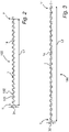
- the joint closure element 100 is designed as a zigzag-shaped strip section 1, which is essentially composed of a number of rectangular segments. This is to be understood as meaning a strip section 1 with a specific material thickness, which has a sequence of extreme deflections in a direction normal to a longitudinal axis 1a of the strip section 1 or of the joint closure element 100 .
- the extreme deflections form the boundaries of the successive segments. In this case, immediately successive extreme deflections extend in opposite directions from the longitudinal axis 1a, such as in particular 2 and 3 can be seen.
- a first extreme deflection 101 and an immediately adjacent second extreme deflection 102 are provided with reference symbols:
- the width of the strip section 1 results from the distance between these extreme deflections 101, 102 in a direction normal to the longitudinal axis 1a of the joint closure element 100.
- the band section 1 of the joint closure element 100 is made of an elastic material.
- elastic is understood to mean the property of absorbing acting tensile forces or acting pressure by deformation and resuming the original shape when the action ends.
- Plastics such as elastomers in particular have this property; for example, the band section 1 can be made of a thermoplastic elastomer.
- the shape and material selection of the joint closure element 100 according to the invention allow its width to be varied by longitudinal stretching—similar to an accordion. If a tensile load is applied to opposite end sections 1′, 1′′ of the strip section 1 in the direction of the longitudinal axis 1a, the result is an elongation with a simultaneous reduction in width.
- FIG. 2 shows a joint closure element 100 according to the invention in the non-assembled state, in which neither the action of a tensile nor a compressive load is present.
- the strip section 1 of the joint closure element 100 has a first width B1 and a first length L1.
- 3 Fig. 12 now shows this joint closure element 100 with an applied load - for example the first end section 1' is held and at the second end section 1" a tensile load is applied along the longitudinal axis 1a in a direction away from the second end section 1" or vice versa, or it is applied at both end sections 1' , 1" a tensile load is applied in opposite directions. Due to the zigzag shape of the strip section 1, the result is an extension to a second length L2 with a simultaneous reduction in width from the first width B1 to a narrower second width B2.
- the second width B2 is 20 percent less than the first width B1, while the second length L2 is 30 percent greater than the first length L1.
- the inventor's tests resulted in a reduction in width of 30 percent and an increase in length by 20 percent.
- the joint closure element 100 If, at the time the tensile load is ended, the joint closure element 100 is placed in a joint 2 that is narrower than the first width B1 but wider than the second width B2, the joint closure element 100 cannot return completely to its starting position with the first width B1, but is jammed himself in the joint 2.
- the joint closure element 100 thus enables simple, in particular also subsequent, laying in joints 2 of wooden terraces 3 and/or between wooden floorboards 4 outdoors, in that the strip section 1 is designed with an oversize compared to a joint width F0 in the non-assembled state.
- the oversize is 1.1 to 1.9 times the joint width F0.
- the zigzag-shaped strip section 1 in the sense of the present invention is not just a strip made of elastic material composed of flat segments, but also an alternatively shaped strip, as long as the clamping effect is guaranteed with appropriate pretensioning as long as the sharpest possible edge is formed between the segments. This avoids surface contact between the strip and the wooden floorboards, so that no accumulations of moisture can form as a result of capillary effects.
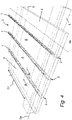
- In 4 is a wooden terrace 3, consisting of wooden floorboards 4, which are mounted on supporting beam elements 5 in the form of upholstered wood, shown, which is located outdoors, ie not carried out inside a building and is therefore exposed to the weather.
- the support beam longitudinal axes 5a run normal to the direction of the floorboard longitudinal axes 4a and the support beam elements 5 are arranged at a support beam spacing S1 of 45 cm from one another.
- the wooden floorboards 4 are arranged at a distance from one another, so that there are 4 joints 2 between the wooden floorboards.
- the Austrian Society for Wood Research (HFA- ⁇ GH) recommends a joint width F0 of at least 7 mm with a wood moisture content of 16 percent to 18 percent when erecting wooden terraces 3 . Since the moisture content of the wood changes due to the weather, the wooden floorboards 4 expand or contract accordingly, so that the joint width F0 varies. Practical measurements by the inventor have shown that the joint width F0 varies in the range of about 2 mm, with an assumed joint width F0 of 7 mm during installation, i.e. between 6 mm and 8 mm, depending on the moisture content of the wood during installation and the weather, larger fluctuations are also possible. The joint closure is thus faced with great challenges, which the invention solves accordingly.
- the width B1 of the strip section 1 of the joint closure element 100 in the non-assembled state is selected such that it has an excess of 1.1 times to 1.9 times the joint width F0 compared to the joint width F0.
- the normal distance between at least two immediately adjacent extreme deflections 101, 102 of the zigzag-shaped strip section 1 in a direction normal to the longitudinal axis 1a of the joint closure element 100 is between the 1.1 Lay up to 1.9 times the joint width F0 of joints 2.
- a joint closure element 100 with a first width B1 of 9.5 mm is used, for example.
- the width of the zigzag-shaped strip section 1 can be reduced by longitudinal traction to such an extent that it can simply be pushed into the joint 2 .
- the restoring force due to the elasticity of the material subsequently causes a permanent clamping in the joint 2 without the need for further mechanical fixation.
- corresponding joint closure elements 100 in the form of zigzag-shaped strip sections 1 are inserted into the joints 2.
- the given, zigzag-shaped geometry in conjunction with the selected, elastic material of the strip section 1 (eg thermoplastic polyolefin), causes a constant adaptation to the thermally hygric changes in the joint width F0 and thus its secure fixation.
- the joint closure element 100 is thus inserted into the joint 2 in such a way that the zigzag course runs in a direction parallel to the surface of the wooden terrace 3 or the wooden floorboards 4, so that the extreme deflections prevent jamming with the side surfaces 4 bordering the joint 2 ' (please refer figure 5 ) of the wooden floorboards 4 takes place.
- the grid-like closure of the joint 2 eliminates the conflict of objectives between the desired security against objects falling through and their physical construction required openness.
- the length of the band sections 1 is selected here so that the second length L2 is greater than the support bar spacing S1 when inserted. This simplifies installation because there is a stop for the strip sections 1 when they are pushed in if the joint closure elements 100 are pushed deeper into the joints 2 .
- the band sections 1 can be pressed in until they are present on the support beam elements 5 .
- the joint width F0 becomes larger than the first width B1 of the strip section 1 - this can be the case with extreme dryness and a corresponding decrease in wood moisture or with age-related decrease in the elasticity of the material of the strip section 1, but also due to Be due to errors when laying - ensures that the joint closure element 100 remains in the joint 2.
- a shorter strip section 1 can also be inserted into a longer strip section 1 in order to bridge a locally limited excess width of the joint 2 .
- the element height H1 (ie the height of the joint closure element 100 or its strip section 1) is selected such that it is between 0.5 times and 1.0 times the plank height H0. this is in figure 5 to discern where a cut along line AA in 4 is shown: The element height is about 0.75 times the floorboard height H0 and the strip section 1 is pushed all the way down into the joint 2, so that between the top of the strip section 1 and the surface of the wooden terrace 3 or the wooden floorboards 4 distance exists.
- the invention thus enables an elastic joint closure element 100 with ventilation for joints 2 of wooden terraces 3 and/or wooden floorboards 4 outdoors, with the selection of a zigzag-shaped geometry in connection with an elastic material allowing water to run off to a large extent from the terrace surface and dry it back from the underground is not affected.
- the formation of the flanks between the joint closure element 100 and the wooden side walls of the wooden floorboards 4 is designed in such a way that no capillary effect occurs.
- the purpose of the joint seal is to prevent insects from penetrating the terrace substructure and to prevent the loss of small objects through the joint. As shown in the figures, this takes place through a zigzag formation of a longitudinally and transversely elastic band section 1 made of plastic (preferably thermoplastic polyolefin).
- this enables simple insertion (reduction in width through longitudinal stretching) and the clamping effect required for fixing is achieved (oversize compared to the joint width F0).
- the grid-like design of the joint closure prevents small objects from falling through.
- the elastic deformability also ensures that the material-related changes in geometry of the joint 2 are accommodated.
- a method according to the invention for sealing joints 2 therefore comprises the following steps: First, a tensile load is applied to at least one of two opposite end sections 1', 1" of the strip section 1 in the longitudinal direction of the joint closure element 100; preferably, such a large tensile load is applied that the first width B1 of the strip section is reduced to a second width B2 , which is smaller than the joint width F0. If the joint 2 is wider or has sections with a greater width, two or more joint closure elements 100 can also be placed one inside the other in a preceding step, or a somewhat shorter section of tape 1 for the wider area can be placed in a longer section of tape 1 to be inserted.
- the joint closure element 100 is inserted into the joint 2. It does not matter whether the wooden terrace 3 has been freshly erected and the installation joint width is available or whether the joint sealing element 100 is introduced at a later point in time when the joint width F0 has changed due to the weather.
- the width of the joint closure element 100 can be adjusted accordingly by varying the tensile load.
- the tensile load on the joint closure element 100 is terminated. Due to the construction of an elastic material and the zigzag shape, the joint closure element 100 tries to restore its original state and to expand from the second width B2 back to the first width B1. This results in the clamping effect of the joint closure element 100 in the joint 2 and its permanent closure.
- the wooden terrace 3 is erected in an outdoor area in a previous step by laying wooden floorboards 4, with joints 2 between adjacent wooden floorboards 4 with a joint width F0 between 5 mm and 9 mm, preferably with a joint width F0 of 7 mm can be executed.
- wood material planks 4 with a wood moisture content of 14 percent to 18 percent are preferred laid, preferably between 16 percent and 18 percent, or it must be ensured before laying that drying is carried out if the wooden floorboards 4 are soaked through, for example due to careless storage.
Description
Die Erfindung betrifft gemäß dem Oberbegriff von Patentanspruch 1 ein Fugenverschlusselement zum Verlegen in Fugen von Holzterrassen und/oder zwischen Holzwerkstoffdielen im Außenbereich mit Belüftung. Die Erfindung betrifft weiter eine Holzterrasse für den Außenbereich. Darüber hinaus betrifft die Erfindung ein Verfahren zum Verschließen von Fugen in Holzterrassen und/oder zwischen Holzwerkstoffdielen im Außenbereich mit einem eingangs erwähnten Fugenverschlusselement.According to the preamble of
Gegenwärtig ist es Stand der Technik, dass Längs- und Querfugen von Holzterrassendielen ebenso wie Dielen aus Holzwerkstoffen offen auszuführen sind. Je nach Material und Verlegetechnik wird für diese offenen Fugen eine Fugenbreite zwischen 5 und 9 mm empfohlen. Diese offene Fugenausbildung ist deswegen technisch notwendig, weil damit die materialbedingte Längs- und Querdehnung der Dielen aufgenommen werden muss und darüber hinaus eine Unterlüftung dieser Bauteile sichergestellt werden soll.It is currently state of the art that longitudinal and transverse joints of wooden decking boards as well as boards made of wood materials are to be open. Depending on the material and laying technique, a joint width of between 5 and 9 mm is recommended for these open joints. This open joint design is technically necessary because the material-related longitudinal and transverse expansion of the floorboards must be absorbed and ventilation of these components should also be ensured.
Im Weiteren bewirken diese offenen Fugen ein Entwässern des Feuchtigkeitanfalls an der Terrassenoberfläche in den Untergrund. Dies ist in manchen Anwendungsfällen erforderlich, wenn beispielsweise ein Vertikalabstand einer wasserführenden Ebene zu Türen eingehalten werden muss.Furthermore, these open joints cause the moisture that accumulates on the terrace surface to drain into the subsoil. This is necessary in some applications if, for example, a vertical distance between a water-bearing level and doors must be maintained.
Offene Fugen weisen aber erhebliche Nachteile auf. Das Eindringen von Ungeziefer in den Zwischenraum unterhalb der Terrassendielen gegen den Untergrund ist uneingeschränkt möglich. Alle Gegenstände in einer Größenordnung unter der Fugenbreite fallen zwischen den Dielen in den nicht mehr zugänglichen Untergrund unter die Terrasse. Bewuchs kann aus dem Untergrund der Terrasse durch die Fugen auf die Terrassenoberfläche ragen. Erschwerend für dieses Problem kommt hinzu, dass diese Terrassendielen zunehmend ohne sichtbare Verschraubung verlegt werden. Dies erhöht zwar die Haltbarkeit der Dielen, macht aber den Zugang in den Bereich unterhalb der Dielen praktisch nur mehr durch einen großflächigen Terrassenabbau möglich.However, open joints have significant disadvantages. There are no restrictions on the ingress of vermin into the space below the decking against the ground. All objects smaller than the joint width fall between the floorboards in the no longer accessible subsoil under the terrace. Plant growth can protrude from the terrace subsoil through the joints onto the terrace surface. This problem is made even more difficult by the fact that these decking boards are increasingly being laid without visible screws. Although this increases the durability of the floorboards, access to the area below the floorboards is practically only possible through large-scale terrace dismantling.
Die
Ähnliche Nachteile weist auch eine Lösung auf, die in der
Aus der
Die
Ferner zeigt die
Es ist daher eine Aufgabe der Erfindung, ein Fugenverschlusselement bzw. eine Holzterrasse mit einem derartigen Fugenverschlusselement bereit zu stellen, so dass die thermisch-hygrische Notwendigkeit einer Stoßfuge berücksichtigt und gleichzeitig deren mechanischer Verschluss ermöglicht wird. Des Weiteren ist es eine Aufgabe der Erfindung, ein Verfahren zum Verschließen von Fugen zwischen Holzwerkstoffdielen ohne Sonderwerkzeug oder spezielle Montageelemente bereit zu stellen, bei dem die oben genannten Bedingungen erfüllt sind.It is therefore an object of the invention to provide a joint closure element or a wooden terrace with such a joint closure element, so that the thermal-hygric necessity of a butt joint is taken into account and at the same time its mechanical closure is made possible. Furthermore, it is an object of the invention to provide a method for closing joints between wooden floorboards without special tools or special assembly elements, in which the above-mentioned conditions are met.
Diese Aufgabe wird durch ein eingangs genanntes Fugenverschlusselement gelöst, das erfindungsgemäß die Merkmale von Patentanspruch 1 aufweist.This object is achieved by a joint closure element mentioned at the outset, which according to the invention has the features of
Insbesondere ist vorgesehen, dass das Fugenverschlusselement als zick-zack-förmiger Bandabschnitt aus einem elastischen Werkstoff ausgeführt ist, wobei das Fugenverschlusselement dazu vorgesehen ist, unter Vorspannung in der Fuge aufgenommen zu sein. Es wird also die Federwirkung des Fugenverschlusselements ausgenutzt, um dieses in der Fuge zu halten, auch wenn Schwankungen der Fugenbreite auftreten.In particular, it is provided that the joint closure element is designed as a zigzag-shaped strip section made of an elastic material, with the Joint closure element is intended to be included under prestress in the joint. So the spring effect of the joint closure element is used to keep it in the joint, even if there are fluctuations in the joint width.
Es ist ein wesentliches Merkmal der Erfindung, dass die zick-zack-förmige Ausbildung einerseits eine Vorspannung in passender Weise gewährleistet und andererseits die Fuge so weit offenlässt, dass Wasser ungehindert abfließen kann und die Belüftung gewährleistet ist.It is an essential feature of the invention that the zigzag-shaped design on the one hand ensures appropriate prestressing and on the other hand leaves the joint open enough that water can drain off unhindered and ventilation is guaranteed.
Vorzugsweise wird die Vorspannung dadurch erzeugt, dass der Bandabschnitt im nicht-montierten Zustand ein Übermaß gegenüber einer Fugenbreite der Fugen vom 1,1-Fachen bis zum 1,9-Fachen der Fugenbreite aufweist. Bei der hier angesprochenen Fugenbreite handelt es sich um den Wert, der bei durchschnittlicher Feuchtigkeit auftritt. Insbesondere bei erhöhter Feuchtigkeit der Holzwerkstoffdielen kann die Fugenbreite deutlich geringer sein.The prestressing is preferably generated in that the strip section has an oversize in the non-assembled state compared to a joint width of the joints of 1.1 times to 1.9 times the joint width. The joint width mentioned here is the value that occurs with average humidity. The joint width can be significantly smaller, especially if the wood-based floorboards are very humid.
Damit wird ein wasserdurchlässiges Fugenverschlusselement zum Schutz gegen das Durchfallen von Kleinteilen für Fugen von Holzterrassen und Holzwerkstoffdielen im Außenbereich bereitgestellt. Durch die Zick-Zack-Form ergibt sich eine Federwirkung auf Längszug, so dass das Fugenverschlusselement besonders leicht in bestehende Terrassen einzubringen ist und eine Variation der Fugenbreite aufgrund von Änderungen der Holzfeuchte ohne Verlust der Klemmwirkung aufgenommen werden kann.This provides a water-permeable joint sealing element to protect against small parts falling through for joints in wooden terraces and wooden floorboards outdoors. The zigzag shape results in a spring effect on longitudinal tension, so that the joint sealing element is particularly easy to insert into existing terraces and a variation in the joint width due to changes in wood moisture can be accommodated without losing the clamping effect.
In einer Variante der Erfindung beträgt im nicht montierten Zustand des Fugenverschlusselements der Normal-Abstand zwischen zumindest zwei unmittelbar benachbarten Extremauslenkungen des zick-zack-förmigen Bandabschnitts in einer Richtung normal zu einer Längsrichtung des Fugenverschlusselements zwischen dem 1,1-Fachen bis zum 1,9-Fachen der Fugenbreite der Fugen.In one variant of the invention, when the joint closure element is not installed, the normal distance between at least two immediately adjacent extreme deflections of the zigzag-shaped strip section in a direction normal to a longitudinal direction of the joint closure element is between 1.1 times and 1.9 -Fold the joint width of the joints.
Vorzugsweise ist vorgesehen, dass das Fugenverschlusselement aus rechteckigen Segmenten besteht, die im Wesentlichen rechtwinkelig zu jeweils benachbarten Segmenten angeordnet sind. Dadurch ist das Fugenverschlusselement in Gebrauchslage senkrecht prismatisch und lässt so den maximal möglichen Querschnitt für das Abfließen von Wasser und die Belüftung frei.Provision is preferably made for the joint closure element to consist of rectangular segments which are arranged essentially at right angles to the respective adjacent segments. As a result, the joint closure element is vertically prismatic when in use, leaving the maximum possible cross-section free for water drainage and ventilation.
Die Aufgabe der Erfindung wird des Weiteren durch eine eingangs genannte Holzterrasse erfindungsgemäß dadurch gelöst, dass in den Fugen zumindest teilweise und/oder abschnittsweise Fugenverschlusselemente der oben beschriebenen Art vorgesehen sind.The object of the invention is also achieved according to the invention by a wooden terrace mentioned at the outset in that joint closure elements of the type described above are provided at least partially and/or in sections in the joints.
Günstigerweise sind dabei die Holzwerkstoffdielen auf Stützbalkenelementen angeordnet, wobei die Stützbalken-Längsachsen quer, vorzugsweise normal zur Richtung einer Dielen-Längsachse verlaufen.The wooden floorboards are advantageously arranged on support beam elements, with the support beam longitudinal axes running transversely, preferably perpendicularly, to the direction of a floorboard's longitudinal axis.
In einer Variante der Erfindung sind dabei die Stützbalkenelemente zueinander in einem Stützbalken-Abstand von 30 cm bis 90 cm, vorzugsweise von 45 cm, angeordnet.In a variant of the invention, the support beam elements are arranged at a support beam distance of 30 cm to 90 cm, preferably 45 cm, from one another.
Die Aufgabe der Erfindung wird außerdem durch ein eingangs genanntes Verfahren zum Verschließen von Fugen in Holzterrassen und/oder zwischen Holzwerkstoffdielen im Außenbereich mit einem Fugenverschlusselement der oben genannten Art erfindungsgemäß durch die folgenden Schritte gelöst:
- a) Aufbringen einer Zugbelastung auf in Längsrichtung des Fugenverschlusselements einander gegenüberliegende Endabschnitte eines Bandabschnitts des Fugenverschlusselements;
- b) Einlegen des Fugenverschlusselements in eine Fuge;
- c) Beenden der Zugbelastung auf das Fugenverschlusselement.
- a) application of a tensile load to opposite end sections of a strip section of the joint closure element in the longitudinal direction of the joint closure element;
- b) inserting the joint closure element into a joint;
- c) Termination of the tensile load on the joint closure element.
Dadurch lässt sich die Federwirkung des erfindungsgenäßen Fugenverschlusselements ausnutzen und ein besonders rasches und zuverlässiges Verschließen der Fuge erreichen.As a result, the spring action of the joint closure element according to the invention can be utilized and the joint can be closed particularly quickly and reliably.
In einer Variante der Erfindung werden in einem vor Schritt a) vorgenommenen Schritt a0) zwei oder mehr Fugenverschlusselemente formschlüssig ineinandergelegt, bevor die Schritte a) bis c) durchgeführt werden. Formschlüssig Ineinanderlegen bedeutet hier, dass die jeweiligen Extremauslenkungen der Bandabschnitte der zwei oder mehr Fugenverschlusselemente in Eingriff gebracht werden, so dass die Bandabschnitte unmittelbar aneinander anliegen. Die Längenveränderung kann dann durch Ausüben der Zugbelastung auf die jeweiligen Endabschnitte gemeinsam erzielt werden. Durch diese Ausführungsvariante können auch breitere Fugen bzw. Fugenabschnitte verlässlich verschlossen werden.In a variant of the invention, in a step a0) carried out before step a), two or more joint closure elements are placed one inside the other in a form-fitting manner before steps a) to c) are carried out. Laying into one another in a form-fitting manner means here that the respective extreme deflections of the strip sections of the two or more joint closure elements are brought into engagement, so that the strip sections bear directly against one another. The change in length can then be achieved by exerting the tensile load on the respective end sections together. With this design variant, wider joints or joint sections can also be reliably sealed.
In einer weiteren Variante wird in einem vor allen anderen Schritten ausgeführten Schritt a00) die Holzterrasse in einem Außenbereich errichtet durch Verlegen von Holzwerkstoffdielen, wobei zwischen benachbarten Holzwerkstoffdielen Fugen mit einer Fugenbreite zwischen 5 mm und 9 mm, vorzugsweise mit einer Fugenbreite von 7 mm ausgeführt werden. Dabei ist es von Vorteil, wenn die Holzwerkstoffdielen mit einer Holzfeuchte von 14 Prozent bis 18 Prozent verlegt werden, vorzugsweise zwischen 16 Prozent und 18 Prozent.In a further variant, in a step a00) carried out before all other steps, the wooden terrace is erected in an outdoor area by laying wood-based material planks, with joints with a joint width of between 5 mm and 9 mm, preferably with a joint width of 7 mm, being made between adjacent wood-based material planks . It is advantageous if the wooden floorboards are laid with a wood moisture content of 14 percent to 18 percent, preferably between 16 percent and 18 percent.
Dadurch kann ein besonders einfaches Einbringen der erfindungsgemäßen Fugenverschlusselemente sichergestellt werden.This ensures a particularly simple introduction of the joint closure elements according to the invention.
Die Erfindung wird nachfolgend anhand eines nicht einschränkenden Ausführungsbeispiels, das in den Figuren dargestellt ist, näher erläutert. Darin zeigen:
- Fig. 1
- eine Schrägdarstellung eines erfindungsgemäßen Fugenverschlusselements;
- Fig. 2
- eine Draufsicht auf ein erfindungsgemäßes Fugenverschlusselement im nicht-montierten Zustand;
- Fig. 3
- eine Draufsicht aus das Fugenverschlusselement aus
Fig. 2 bei Einwirken einer Zugbelastung in Längsrichtung; - Fig. 4
- eine perspektivische Darstellung einer erfindungsgemäßen Holzterrasse mit Fugenverschlusselementen; und
- Fig. 5
- eine Schnittansicht der Holzterrasse entlang der Linie A-A in
Fig. 4 .
- 1
- an oblique view of a joint closure element according to the invention;
- 2
- a plan view of a joint closure element according to the invention in the non-assembled state;
- 3
- a top view of the
joint closure element 2 when subjected to a tensile load in the longitudinal direction; - 4
- a perspective view of a wooden terrace according to the invention with joint closure elements; and
- figure 5
- a sectional view of the wooden deck along the line AA in
4 .
In
In
Während in den vorliegenden Figuren ein Ausführungsbeispiel dargestellt ist, in dem der Absolutwert aller Auslenkungen hinsichtlich der Längsachse 1a gleich gewählt ist, sind auch Varianten möglich, in denen die Extremauslenkungen über die Längserstreckung des Bandabschnitts 1 variieren. Die Breite wird dann durch den größten Abstand zwischen benachbarten Extremauslenkungen definiert.While the present figures show an exemplary embodiment in which the absolute value of all deflections with respect to the
Der Bandabschnitt 1 des Fugenverschlusselement 100 ist aus einem elastischen Werkstoff gefertigt. Unter elastisch wird in der vorliegenden Offenbarung die Eigenschaft verstanden, einwirkende Zugkräfte oder einwirkenden Druck durch Verformung aufzunehmen und bei Beenden der Einwirkung wieder die ursprüngliche Form einzunehmen. Diese Eigenschaft bringen insbesondere Kunststoffe wie z.B. Elastomere mit sich; so kann der Bandabschnitt 1 beispielsweise aus einem thermoplastischen Elastomer gefertigt sein.The
Erfindungsgemäße Form und Materialwahl des Fugenverschlusselements 100 erlauben es, dass seine Breite durch Längsdehnung variiert werden kann - ähnlich einer Ziehharmonika. Wenn also eine Zugbelastung auf in Richtung der Längsachse 1a gegenüberliegende Endabschnitte 1', 1" des Bandabschnitts 1 aufgebracht wird, ergibt sich eine Verlängerung bei gleichzeitiger Reduzierung der Breite.The shape and material selection of the
Beispielsweise ist beim Ausführungsbeispiel gemäß
Wird die Zugbelastung des Fugenverschlusselements 100 beendet, wird wieder die in
Wenn zum Zeitpunkt des Beendens der Zugbelastung das Fugenverschlusselement 100 in eine Fuge 2 eingelegt wird, die schmäler ist als die erste Breite B1 aber breiter als die zweite Breite B2, kann das Fugenverschlusselement 100 nicht vollständig in seine Ausgangsposition mit der ersten Breite B1 zurück sondern verklemmt sich in der Fuge 2.If, at the time the tensile load is ended, the
Damit ermöglicht das erfindungsgemäße Fugenverschlusselement 100 ein einfaches, insbesondere auch nachträgliches, Verlegen in Fugen 2 von Holzterrassen 3 und/oder zwischen Holzwerkstoffdielen 4 im Außenbereich, indem der Bandabschnitt 1 im nicht-montierten Zustand mit einem Übermaß gegenüber einer Fugenbreite F0 ausgeführt ist. Insbesondere beträgt das Übermaß das 1,1-Fache bis zum 1,9-Fachen der Fugenbreite F0.The
Es ist festzuhalten, dass als zick-zack-förmiger Bandabschnitt 1 im Sinn der vorliegenden Erfindung nicht nur ein aus ebenen Segmenten zusammengesetzter Streifen aus elastischem Material zu verstehen ist, sondern auch ein alternativ geformter Streifen, so lange die Klemmwirkung bei entsprechenden Vorspannung gewährleistet ist und so lange zwischen den Segmenten eine möglichst scharfe Kante ausgebildet ist. Dadurch wird eine flächige Berührung zwischen dem Streifen und den Holzwerkstoffdielen vermieden, so dass sich keine Feuchtigkeitsansammlungen zufolge von Kapillareffekten bilden können.It should be noted that the zigzag-shaped
In
Die Holzwerkstoffdielen 4 sind mit Abstand zueinander angeordnet, so dass sich zwischen den Holzwerkstoffdielen 4 Fugen 2 ergeben.The
Die Österreichische Gesellschaft für Holzforschung (HFA-ÖGH) empfiehlt beim Errichten von Holzterrassen 3 eine Fugenbreite F0 von mindestens 7 mm bei einer Holzfeuchte von 16 Prozent bis 18 Prozent. Da sich die Holzfeuchte witterungsbedingt ändert, dehnen sich die Holzwerkstoffdielen 4 entsprechend aus oder ziehen sich zusammen, so dass die Fugenbreite F0 variiert. Praktische Messungen des Erfinders haben ergeben, dass die Fugenbreite F0 im Bereich von etwa 2 mm variiert, bei einer angenommenen Fugenbreite F0 von 7 mm beim Einbau also zwischen 6 mm und 8 mm schwankt, wobei je nach Holzfeuchte beim Einbau und Witterung auch größere Schwankungen möglich sind. Damit wird der Fugenverschluss vor große Herausforderungen gestellt, die die Erfindung entsprechend löst.The Austrian Society for Wood Research (HFA-ÖGH) recommends a joint width F0 of at least 7 mm with a wood moisture content of 16 percent to 18 percent when erecting wooden terraces 3 . Since the moisture content of the wood changes due to the weather, the
Die Breite B1 des Bandabschnitts 1 des Fugenverschlusselements 100 im nicht montierten Zustand wird so gewählt, dass sie gegenüber der Fugenbreite F0 ein Übermaß vom 1,1-Fachen bis zum 1,9-Fachem der Fugenbreite F0 aufweist. In einer Variante der Erfindung wird im nicht montierten Zustand des Fugenverschlusselements 100 der Normal-Abstand zwischen zumindest zwei unmittelbar benachbarten Extremauslenkungen 101, 102 des zick-zack-förmigen Bandabschnitts 1 in einer Richtung normal zur Längsachse 1a des Fugenverschlusselements 100 zwischen dem 1,1-Fachen bis zum 1,9-Fachen der Fugenbreite F0 der Fugen 2 ausgeführt. Im oben beschriebenen Fall einer Einbau-Fugendichte F0 von 7 mm wird beispielsweise ein Fugenverschlusselement 100 mit einer ersten Breite B1 von 9,5 mm verwendet.The width B1 of the
Die Breite des zick-zack-förmigen Bandabschnitts 1 lässt sich durch Längszug soweit reduzieren, dass ein einfaches Einschieben in die Fuge 2 möglich wird. Die Rückstellkraft aufgrund der Elastizität des Materials bewirkt in weiterer Folge eine dauerhafte Klemmung in der Fuge 2, ohne dass eine weitere mechanische Fixierung erforderlich ist. Die Formgebung gewährleistet durch das Offenbleiben von gleichschenkeligen Dreiecken (Prismen) als durchgängige Öffnung ein sicheres Abfließen des Oberflächenwassers von der Oberfläche der Holzterrasse 3 in den Untergrund. Da die Berührung mit der Flanke - also den die Fuge 2 begrenzenden Seitenflächen 4' - der Holzwerkstoffdielen 4 nur über einzelne, kurze Linien an der Spitze der besagten gleichschenkeligen Dreiecksprismen erfolgt, wird die Bildung einer kapillar saugenden Grenzfläche verhindert. Damit ist sichergestellt, dass die Flankenzone gegenüber der Dielenfläche keine erhöhte Holzfeuchte annimmt.The width of the zigzag-shaped
In
Durch den gitterförmigen Verschluss der Fuge 2 wird der Zielkonflikt zwischen der gewünschten Sicherung gegen das Durchfallen von Gegenständen und deren bauphysikalisch geforderten Offenheit gelöst. Die Länge der Bandabschnitte 1 ist hier so gewählt, dass die zweite Länge L2 im eingelegten Zustand größer ist als der Stützbalkenabstand S1. Dadurch wird der Einbau erleichtert, weil beim Einschieben ein Anschlag für die Bandabschnitte 1 gegeben ist, falls die Fugenverschlusselemente 100 tiefer in die Fugen 2 hineingeschoben werden. Die Bandabschnitte 1 können so weit hineingedrückt werden, bis sie an den Stützbalkenelementen 5 anstehen.The grid-like closure of the joint 2 eliminates the conflict of objectives between the desired security against objects falling through and their physical construction required openness. The length of the
Dadurch ist auch für den Fall, dass die Fugenbreite F0 größer wird als die erste Breite B1 des Bandabschnitts 1 - dies kann bei extremer Trockenheit und entsprechender Abnahme der Holzfeuchte oder bei altersbedingtem Abnehmen der Elastizität des Materials des Bandabschnitts 1 der Fall sein, aber auch durch Fehler beim Verlegen bedingt sein - sichergestellt, dass das Fugenverschlusselement 100 in der Fuge 2 verbleibt. In einem solchen Fall kann zusätzlich auch vorgesehen werden, dass beim Einsetzen der Fugenverschlusselemente 100 jeweils zwei Bandabschnitte 1 formschlüssig ineinandergelegt und erst dann eingelegt werden. Dabei kann auch ein kürzerer Bandabschnitt 1 in einen längeren Bandabschnitt 1 eingelegt werden, um eine örtlich begrenzte Überbreite der Fuge 2 zu überbrücken.As a result, in the event that the joint width F0 becomes larger than the first width B1 of the strip section 1 - this can be the case with extreme dryness and a corresponding decrease in wood moisture or with age-related decrease in the elasticity of the material of the
Im dargestellten Ausführungsbeispiel wird die Elementhöhe H1 (also die Höhe des Fugenverschlusselements 100 bzw. dessen Bandabschnitt 1) so gewählt, dass sie zwischen dem 0,5-Fachen und dem 1,0-Fachen der Dielenhöhe H0 beträgt. Dies ist in
Die Erfindung ermöglicht damit ein elastisches Fugenverschlusselement 100 mit Belüftung für Fugen 2 von Holzterrassen 3 und/oder Holzwerkstoffdielen 4 im Außenbereich, wobei durch die Wahl einer zickzackförmigen Geometrie in Verbindung mit einem elastischen Material ein weitgehender Abfluss von Wasser aus der Terrassenoberfläche möglich ist und ein Rücktrocknen aus dem Untergrund nicht beeinträchtigt wird. Die Flankenausbildung zwischen Fugenverschlusselement 100 und Holz-Seitenwangen der Holzwerkstoffdielen 4 ist so ausgebildet, dass kein Kapillareffekt entsteht. Zweck des Fugenverschlusses ist es, das Eindringen von Insekten in den Terrassenuntergrund hintanzuhalten und den Verlust von Kleingegenständen durch die Fuge zu verhindern. Wie in den Figuren dargestellt erfolgt dies durch eine zickzackförmige Ausbildung eines längs und querelastischen Bandabschnitts 1 aus Kunststoff (vorzugsweise Thermoplastisches Polyolefin). Damit wird einerseits eine einfache Einbringung (Breitenreduktion durch Längs-Dehnung) und die zur Fixierung erforderliche Klemmwirkung erreicht (Übermaß gegenüber der Fugenbreite F0). Andererseits verhindert die gitterförmige Ausbildung des Fugenverschlusses das Durchfallen von Kleingegenständen. Die elastische Verformbarkeit sichert darüber hinaus die Aufnahme der materialbedingten Geometrieänderungen der Fuge 2. Um die Klemmwirkung zu verbessern kann der Bandabschnitt 1 auch mit einer Oberflächenstruktur versehen werden, die ein besseres Zusammenwirken mit den Holzwerkstoffdielen 4 erlaubt.The invention thus enables an elastic
Auch das Verlegen des Fugenverschlusselements 100 ist einfach möglich. Ein erfindungsgemäßes Verfahren zum Verschließen von Fugen 2 umfasst demnach die folgenden Schritte:
Zuerst wird eine Zugbelastung auf zumindest einen von zwei in Längsrichtung des Fugenverschlusselements 100 einander gegenüberliegende Endabschnitte 1', 1" des Bandabschnitts 1 aufgebracht; bevorzugt wird dabei eine so große Zugbelastung aufgebracht, dass sich die erste Breite B1 des Bandabschnitts zu einer zweiten Breite B2 reduziert, die geringer ist als die Fugenbreite F0. Wenn die Fuge 2 breiter ist oder Abschnitte mit größerer Breite aufweist, können in einem vorgelagerten Schritt auch zwei oder mehr Fugenverschlusselemente 100 ineinandergelegt werden bzw. ein etwas kürzerer Bandabschnitt 1 für den breiteren Bereich in einen längeren Bandabschnitt 1 eingelegt werden.Laying the
First, a tensile load is applied to at least one of two
In einem nächsten Schritt wird das Fugenverschlusselement 100 in die Fuge 2 eingelegt. Dabei spielt es keine Rolle, ob die Holzterrasse 3 frisch errichtet worden ist und die Einbaufugenbreite vorliegt oder ob das Fugenverschlusselement 100 zu einem späteren Zeitpunkt eingebracht wird, wenn die Fugenbreite F0 sich witterungsbedingt geändert hat. Durch Variieren der Zugbelastung kann die Breite des Fugenverschlusselements 100 entsprechend angepasst werden.In a next step, the
Zum Abschluss wird die Zugbelastung auf das Fugenverschlusselement 100 beendet. Aufgrund der Ausführung aus einem elastischen Werkstoff und die Zick-Zack-Form versucht das Fugenverschlusselement 100, seinen ursprünglichen Zustand wiederherzustellen und sich von der zweiten Breite B2 wieder in die erste Breite B1 auszudehnen. So ergibt sich die Klemmwirkung des Fugenverschlusselements 100 in der Fuge 2 und deren dauerhafter Verschluss.Finally, the tensile load on the
Wird das Verschließen der Fugen 2 unmittelbar beim Einbau vorgenommen wird in einem vorherigen Schritt die Holzterrasse 3 in einem Außenbereich errichtet durch Verlegen von Holzwerkstoffdielen 4, wobei zwischen benachbarten Holzwerkstoffdielen 4 Fugen 2 mit einer Fugenbreite F0 zwischen 5 mm und 9 mm, vorzugsweise mit einer Fugenbreite F0 von 7 mm ausgeführt werden. Dabei werden vorzugsweise Holzwerkstoffdielen 4 mit einer Holzfeuchte von 14 Prozent bis 18 Prozent verlegt, vorzugsweise zwischen 16 Prozent und 18 Prozent, bzw. ist vor dem Verlegen sicherzustellen, dass eine Trocknung durchgeführt wird, falls die Holzwerkstoffdielen 4 z.B. durch nachlässige Lagerung durchfeuchtet sind.If the
Im Abschluss daran erfolgt das Verlegen wie oben beschrieben.Finally, the laying is carried out as described above.
Claims (13)
- Wooden terrace (3) for outdoor use with ventilation, consisting at least of wooden material boards (4), between which gaps (2) are formed, wherein in the gaps (2) at least partially and/or in sections in each case a gap closure element (100) for laying in gaps (2) of wooden terraces (3) and/or between wooden material boards (4) in outdoor use with ventilation is accommodated under pretension, characterised in that the gap closure element leaves the gap open to such an extent that water can flow off unhindered, which gap closure element (100) is designed as a zigzag-shaped strip section (1) made of an elastic material.
- Wooden terrace (3) according to claim 1, characterised in that the strip section (1) of the gap closure element (100) in the non-assembled state has an oversize relative to a gap width (F0) of the gaps (2) from 1.1 times to 1.9 times the gap width (F0).
- Wooden terrace (3) according to one of claims 1 or 2, characterised in that in the non-assembled state of the gap closure element (100), the normal distance between at least two directly adjacent extreme deflections (101, 102) of the zigzag-shaped strip section (1) in a direction normal to a longitudinal axis (1a) of the gap closure element (100) is between 1.1 times and up to 1.9 times the gap width (F0) of the gaps (2).
- Wooden terrace (3) according to one of claims 1 to 3, characterised in that the gap closure element (100) consists of rectangular segments arranged substantially at right angles to respective adjacent segments.
- Wooden terrace (3) according to one of claims 1 to 4, characterised in that the gap closure element (100) consists of segments between which edges are provided in each case.
- Wooden terrace (3) according to one of the claims 1 to 5, characterised in that the gaps (2) are designed with a gap width (F0) between 5 mm and 9 mm, preferably with a gap width (F0) of 7 mm.
- Wooden terrace (3) according to one of the claims 1 to 6, characterised in that the wooden material boards (4) are arranged on supporting beam elements (5), wherein the supporting beam longitudinal axes (5a) extend transversely, preferably perpendicularly, to the direction of a board longitudinal axis (4a).
- Wooden terrace (3) according to claim 7, characterised in that the supporting beam elements (5) are arranged at a supporting beam spacing (S1) of 30 cm to 90 cm, preferably of about 45 cm, from each other.
- Wooden terrace (3) according to one of claims 1 to 8, characterised in that the gap closure element (100) leaves at least 50%, preferably at least 70%, of the cross-section of the gap (2) open in the installed state.
- Method for closing gaps (2) in wooden terraces (3) and/or between wooden material boards (4) in the outdoor area with a gap closure element (100) according to one of the claims 1 to 9, characterised by the following steps:a) applying a tensile load to end sections (1', 1") of a strip section (1) of the gap closure element (100) that are opposite one another in the longitudinal direction of the gap closure element (100);b) inserting the gap closure element (100) into a gap (2);c) terminating the tensile load on the gap closure element (100).
- Method according to claim 10, characterised in that, in a step a0) carried out before step a), two or more gap closure elements (100) are placed in one another in a form-fitting manner before steps a) to c) are carried out.
- Method according to one of the claims 10 or 11, characterised in that, in a step a00) carried out before all the other steps, the wooden terrace (3) is erected in an outdoor area by laying wooden material boards (4), wherein gaps (2) with a gap width (F0) of between 5 mm and 9 mm, preferably with a gap width (F0) of 7 mm, are made between adjacent wooden material boards (4).
- Method according to one of claims 10 to 12, characterised in that the wooden material boards (4) are laid with a wood moisture content of 14 percent to 18 percent, preferably between 16 percent and 18 percent.
Applications Claiming Priority (1)
| Application Number | Priority Date | Filing Date | Title |
|---|---|---|---|
| ATA190/2019A AT521692B1 (en) | 2019-05-20 | 2019-05-20 | Joint closure element and wooden terrace with joint closure element |
Publications (2)
| Publication Number | Publication Date |
|---|---|
| EP3741925A1 EP3741925A1 (en) | 2020-11-25 |
| EP3741925B1 true EP3741925B1 (en) | 2022-10-12 |
Family
ID=70328909
Family Applications (1)
| Application Number | Title | Priority Date | Filing Date |
|---|---|---|---|
| EP20167679.8A Active EP3741925B1 (en) | 2019-05-20 | 2020-04-02 | Wooden terrace with gap sealing element and method for closing joints in wooden terraces |
Country Status (3)
| Country | Link |
|---|---|
| EP (1) | EP3741925B1 (en) |
| AT (1) | AT521692B1 (en) |
| DK (1) | DK3741925T3 (en) |
Citations (2)
| Publication number | Priority date | Publication date | Assignee | Title |
|---|---|---|---|---|
| DE19940837A1 (en) * | 1998-10-26 | 2000-11-23 | Karl Boeckl | Floor laying system comprises alignment elements and plate elements with cutouts which are dimensioned so that the alignment elements are easily slidable into their respective cutouts |
| EP1083269B1 (en) * | 1999-09-11 | 2004-10-20 | Walter Gutjahr | Aid for laying covering plates in a raised or ventilated position |
Family Cites Families (5)
| Publication number | Priority date | Publication date | Assignee | Title |
|---|---|---|---|---|
| CH466533A (en) * | 1967-09-05 | 1968-12-15 | Daetwyler Ag | Sealing strip made of elastically deformable material |
| DE9319436U1 (en) * | 1993-12-17 | 1994-03-03 | Moissl Johann | Wooden floor |
| DE29917335U1 (en) * | 1999-10-02 | 2001-02-15 | Gutjahr Walter | Joint bar for floor slabs of paving laid on pedestals |
| AT5920U3 (en) | 2002-09-23 | 2003-06-25 | Michael Ing Krippl | WOODEN FLOOR WITH SEAL FOR OUTDOOR USE |
| KR101549065B1 (en) * | 2015-01-20 | 2015-09-03 | 주식회사 기린에스아이 | deck road and wood-bridge system |
-
2019
- 2019-05-20 AT ATA190/2019A patent/AT521692B1/en active
-
2020
- 2020-04-02 DK DK20167679.8T patent/DK3741925T3/en active
- 2020-04-02 EP EP20167679.8A patent/EP3741925B1/en active Active
Patent Citations (2)
| Publication number | Priority date | Publication date | Assignee | Title |
|---|---|---|---|---|
| DE19940837A1 (en) * | 1998-10-26 | 2000-11-23 | Karl Boeckl | Floor laying system comprises alignment elements and plate elements with cutouts which are dimensioned so that the alignment elements are easily slidable into their respective cutouts |
| EP1083269B1 (en) * | 1999-09-11 | 2004-10-20 | Walter Gutjahr | Aid for laying covering plates in a raised or ventilated position |
Also Published As
| Publication number | Publication date |
|---|---|
| AT521692B1 (en) | 2020-04-15 |
| DK3741925T3 (en) | 2023-01-16 |
| AT521692A4 (en) | 2020-04-15 |
| EP3741925A1 (en) | 2020-11-25 |
Similar Documents
| Publication | Publication Date | Title |
|---|---|---|
| EP3581732B1 (en) | Panel with sealing crease and sealing ridge | |
| EP1200690A1 (en) | Method for placing and blocking panels | |
| DE2719857C2 (en) | ||
| DE2935745C2 (en) | Noise barrier | |
| EP3741925B1 (en) | Wooden terrace with gap sealing element and method for closing joints in wooden terraces | |
| DE202013100629U1 (en) | web profile | |
| AT511661B1 (en) | CONNECTION ASSEMBLY OF SIDE-GROUNDED FLOOR OR WALL BOARD | |
| DE2647839B2 (en) | Joint sealing profile made of plastic to close a joint | |
| DE3444305A1 (en) | Structural unit for forming a wall, ceiling or door of a sauna cubicle or steam-bath cubicle | |
| EP2848747A1 (en) | Façade cladding | |
| EP3420158B1 (en) | Device for locking two floor panels | |
| DE202004004107U1 (en) | Covering consisting of individual plates made of mineral material | |
| EP3733995B1 (en) | Weather-protected wood floor device | |
| DE102014101112B4 (en) | Cladding for building parts | |
| DE20314720U1 (en) | Wooden floor, comprises wooden floor boards with a sealing profile located between them | |
| EP3208396B1 (en) | Rail system | |
| DE202012007345U1 (en) | Connecting component for building a substantially flat surface | |
| DE102015205095B4 (en) | Ski mat segment and ski mat | |
| EP0860562B1 (en) | Floor as well as method of laying | |
| CH686383A5 (en) | Process for preventing profile sealing strip moving relatively to tunnel structural element | |
| DE102008051440B4 (en) | panel member | |
| DE19513700C1 (en) | Roller-blind with curved wall strips | |
| DE2357318A1 (en) | PROCESS FOR THE PRODUCTION OF CONCRETE COVERINGS AND ELEMENT FOR SEALING JOINTS AND CRACKS IN THE COATING | |
| AT407174B (en) | EDGE STRIPS ON ROOF ELEVAS | |
| DE2202083A1 (en) | SEAL FOR STRUCTURAL JOINTS |
Legal Events
| Date | Code | Title | Description |
|---|---|---|---|
| PUAI | Public reference made under article 153(3) epc to a published international application that has entered the european phase |
Free format text: ORIGINAL CODE: 0009012 |
|
| STAA | Information on the status of an ep patent application or granted ep patent |
Free format text: STATUS: THE APPLICATION HAS BEEN PUBLISHED |
|
| AK | Designated contracting states |
Kind code of ref document: A1 Designated state(s): AL AT BE BG CH CY CZ DE DK EE ES FI FR GB GR HR HU IE IS IT LI LT LU LV MC MK MT NL NO PL PT RO RS SE SI SK SM TR |
|
| AX | Request for extension of the european patent |
Extension state: BA ME |
|
| STAA | Information on the status of an ep patent application or granted ep patent |
Free format text: STATUS: REQUEST FOR EXAMINATION WAS MADE |
|
| 17P | Request for examination filed |
Effective date: 20210419 |
|
| RBV | Designated contracting states (corrected) |
Designated state(s): AL AT BE BG CH CY CZ DE DK EE ES FI FR GB GR HR HU IE IS IT LI LT LU LV MC MK MT NL NO PL PT RO RS SE SI SK SM TR |
|
| STAA | Information on the status of an ep patent application or granted ep patent |
Free format text: STATUS: EXAMINATION IS IN PROGRESS |
|
| 17Q | First examination report despatched |
Effective date: 20220527 |
|
| GRAP | Despatch of communication of intention to grant a patent |
Free format text: ORIGINAL CODE: EPIDOSNIGR1 |
|
| STAA | Information on the status of an ep patent application or granted ep patent |
Free format text: STATUS: GRANT OF PATENT IS INTENDED |
|
| INTG | Intention to grant announced |
Effective date: 20220706 |
|
| GRAS | Grant fee paid |
Free format text: ORIGINAL CODE: EPIDOSNIGR3 |
|
| GRAA | (expected) grant |
Free format text: ORIGINAL CODE: 0009210 |
|
| STAA | Information on the status of an ep patent application or granted ep patent |
Free format text: STATUS: THE PATENT HAS BEEN GRANTED |
|
| AK | Designated contracting states |
Kind code of ref document: B1 Designated state(s): AL AT BE BG CH CY CZ DE DK EE ES FI FR GB GR HR HU IE IS IT LI LT LU LV MC MK MT NL NO PL PT RO RS SE SI SK SM TR |
|
| REG | Reference to a national code |
Ref country code: GB Ref legal event code: FG4D Free format text: NOT ENGLISH |
|
| REG | Reference to a national code |
Ref country code: CH Ref legal event code: EP |
|
| REG | Reference to a national code |
Ref country code: DE Ref legal event code: R096 Ref document number: 502020001823 Country of ref document: DE |
|
| REG | Reference to a national code |
Ref country code: IE Ref legal event code: FG4D Free format text: LANGUAGE OF EP DOCUMENT: GERMAN |
|
| REG | Reference to a national code |
Ref country code: AT Ref legal event code: REF Ref document number: 1524254 Country of ref document: AT Kind code of ref document: T Effective date: 20221115 |
|
| REG | Reference to a national code |
Ref country code: NL Ref legal event code: FP |
|
| REG | Reference to a national code |
Ref country code: DK Ref legal event code: T3 Effective date: 20230113 |
|
| PGFP | Annual fee paid to national office [announced via postgrant information from national office to epo] |
Ref country code: NL Payment date: 20221230 Year of fee payment: 4 |
|
| REG | Reference to a national code |
Ref country code: SE Ref legal event code: TRGR |
|
| REG | Reference to a national code |
Ref country code: LT Ref legal event code: MG9D |
|
| PG25 | Lapsed in a contracting state [announced via postgrant information from national office to epo] |
Ref country code: PT Free format text: LAPSE BECAUSE OF FAILURE TO SUBMIT A TRANSLATION OF THE DESCRIPTION OR TO PAY THE FEE WITHIN THE PRESCRIBED TIME-LIMIT Effective date: 20230213 Ref country code: NO Free format text: LAPSE BECAUSE OF FAILURE TO SUBMIT A TRANSLATION OF THE DESCRIPTION OR TO PAY THE FEE WITHIN THE PRESCRIBED TIME-LIMIT Effective date: 20230112 Ref country code: LT Free format text: LAPSE BECAUSE OF FAILURE TO SUBMIT A TRANSLATION OF THE DESCRIPTION OR TO PAY THE FEE WITHIN THE PRESCRIBED TIME-LIMIT Effective date: 20221012 Ref country code: FI Free format text: LAPSE BECAUSE OF FAILURE TO SUBMIT A TRANSLATION OF THE DESCRIPTION OR TO PAY THE FEE WITHIN THE PRESCRIBED TIME-LIMIT Effective date: 20221012 Ref country code: ES Free format text: LAPSE BECAUSE OF FAILURE TO SUBMIT A TRANSLATION OF THE DESCRIPTION OR TO PAY THE FEE WITHIN THE PRESCRIBED TIME-LIMIT Effective date: 20221012 |
|
| PGFP | Annual fee paid to national office [announced via postgrant information from national office to epo] |
Ref country code: FR Payment date: 20230323 Year of fee payment: 4 |
|
| PG25 | Lapsed in a contracting state [announced via postgrant information from national office to epo] |
Ref country code: RS Free format text: LAPSE BECAUSE OF FAILURE TO SUBMIT A TRANSLATION OF THE DESCRIPTION OR TO PAY THE FEE WITHIN THE PRESCRIBED TIME-LIMIT Effective date: 20221012 Ref country code: PL Free format text: LAPSE BECAUSE OF FAILURE TO SUBMIT A TRANSLATION OF THE DESCRIPTION OR TO PAY THE FEE WITHIN THE PRESCRIBED TIME-LIMIT Effective date: 20221012 Ref country code: LV Free format text: LAPSE BECAUSE OF FAILURE TO SUBMIT A TRANSLATION OF THE DESCRIPTION OR TO PAY THE FEE WITHIN THE PRESCRIBED TIME-LIMIT Effective date: 20221012 Ref country code: IS Free format text: LAPSE BECAUSE OF FAILURE TO SUBMIT A TRANSLATION OF THE DESCRIPTION OR TO PAY THE FEE WITHIN THE PRESCRIBED TIME-LIMIT Effective date: 20230212 Ref country code: HR Free format text: LAPSE BECAUSE OF FAILURE TO SUBMIT A TRANSLATION OF THE DESCRIPTION OR TO PAY THE FEE WITHIN THE PRESCRIBED TIME-LIMIT Effective date: 20221012 Ref country code: GR Free format text: LAPSE BECAUSE OF FAILURE TO SUBMIT A TRANSLATION OF THE DESCRIPTION OR TO PAY THE FEE WITHIN THE PRESCRIBED TIME-LIMIT Effective date: 20230113 |
|
| PGFP | Annual fee paid to national office [announced via postgrant information from national office to epo] |
Ref country code: BE Payment date: 20230323 Year of fee payment: 4 |
|
| P01 | Opt-out of the competence of the unified patent court (upc) registered |
Effective date: 20230509 |
|
| REG | Reference to a national code |
Ref country code: DE Ref legal event code: R097 Ref document number: 502020001823 Country of ref document: DE |
|
| PG25 | Lapsed in a contracting state [announced via postgrant information from national office to epo] |
Ref country code: SM Free format text: LAPSE BECAUSE OF FAILURE TO SUBMIT A TRANSLATION OF THE DESCRIPTION OR TO PAY THE FEE WITHIN THE PRESCRIBED TIME-LIMIT Effective date: 20221012 Ref country code: RO Free format text: LAPSE BECAUSE OF FAILURE TO SUBMIT A TRANSLATION OF THE DESCRIPTION OR TO PAY THE FEE WITHIN THE PRESCRIBED TIME-LIMIT Effective date: 20221012 Ref country code: EE Free format text: LAPSE BECAUSE OF FAILURE TO SUBMIT A TRANSLATION OF THE DESCRIPTION OR TO PAY THE FEE WITHIN THE PRESCRIBED TIME-LIMIT Effective date: 20221012 Ref country code: CZ Free format text: LAPSE BECAUSE OF FAILURE TO SUBMIT A TRANSLATION OF THE DESCRIPTION OR TO PAY THE FEE WITHIN THE PRESCRIBED TIME-LIMIT Effective date: 20221012 |
|
| PGFP | Annual fee paid to national office [announced via postgrant information from national office to epo] |
Ref country code: DK Payment date: 20230419 Year of fee payment: 4 Ref country code: DE Payment date: 20230112 Year of fee payment: 4 Ref country code: CH Payment date: 20230502 Year of fee payment: 4 |
|
| PLBE | No opposition filed within time limit |
Free format text: ORIGINAL CODE: 0009261 |
|
| STAA | Information on the status of an ep patent application or granted ep patent |
Free format text: STATUS: NO OPPOSITION FILED WITHIN TIME LIMIT |
|
| PG25 | Lapsed in a contracting state [announced via postgrant information from national office to epo] |
Ref country code: SK Free format text: LAPSE BECAUSE OF FAILURE TO SUBMIT A TRANSLATION OF THE DESCRIPTION OR TO PAY THE FEE WITHIN THE PRESCRIBED TIME-LIMIT Effective date: 20221012 Ref country code: AL Free format text: LAPSE BECAUSE OF FAILURE TO SUBMIT A TRANSLATION OF THE DESCRIPTION OR TO PAY THE FEE WITHIN THE PRESCRIBED TIME-LIMIT Effective date: 20221012 |
|
| PGFP | Annual fee paid to national office [announced via postgrant information from national office to epo] |
Ref country code: SE Payment date: 20230419 Year of fee payment: 4 |
|
| 26N | No opposition filed |
Effective date: 20230713 |
|
| PG25 | Lapsed in a contracting state [announced via postgrant information from national office to epo] |
Ref country code: SI Free format text: LAPSE BECAUSE OF FAILURE TO SUBMIT A TRANSLATION OF THE DESCRIPTION OR TO PAY THE FEE WITHIN THE PRESCRIBED TIME-LIMIT Effective date: 20221012 |
|
| PG25 | Lapsed in a contracting state [announced via postgrant information from national office to epo] |
Ref country code: LU Free format text: LAPSE BECAUSE OF NON-PAYMENT OF DUE FEES Effective date: 20230402 |
|
| PG25 | Lapsed in a contracting state [announced via postgrant information from national office to epo] |
Ref country code: MC Free format text: LAPSE BECAUSE OF FAILURE TO SUBMIT A TRANSLATION OF THE DESCRIPTION OR TO PAY THE FEE WITHIN THE PRESCRIBED TIME-LIMIT Effective date: 20221012 |
|
| PG25 | Lapsed in a contracting state [announced via postgrant information from national office to epo] |
Ref country code: MC Free format text: LAPSE BECAUSE OF FAILURE TO SUBMIT A TRANSLATION OF THE DESCRIPTION OR TO PAY THE FEE WITHIN THE PRESCRIBED TIME-LIMIT Effective date: 20221012 |
|
| REG | Reference to a national code |
Ref country code: IE Ref legal event code: MM4A |
|
| PG25 | Lapsed in a contracting state [announced via postgrant information from national office to epo] |
Ref country code: IE Free format text: LAPSE BECAUSE OF NON-PAYMENT OF DUE FEES Effective date: 20230402 |
|
| PG25 | Lapsed in a contracting state [announced via postgrant information from national office to epo] |
Ref country code: IE Free format text: LAPSE BECAUSE OF NON-PAYMENT OF DUE FEES Effective date: 20230402 |