EP3581732B1 - Panel with sealing crease and sealing ridge - Google Patents
Panel with sealing crease and sealing ridge Download PDFInfo
- Publication number
- EP3581732B1 EP3581732B1 EP18178064.4A EP18178064A EP3581732B1 EP 3581732 B1 EP3581732 B1 EP 3581732B1 EP 18178064 A EP18178064 A EP 18178064A EP 3581732 B1 EP3581732 B1 EP 3581732B1
- Authority
- EP
- European Patent Office
- Prior art keywords
- panel
- hook
- groove
- locking
- arresting
- Prior art date
- Legal status (The legal status is an assumption and is not a legal conclusion. Google has not performed a legal analysis and makes no representation as to the accuracy of the status listed.)
- Active
Links
- 238000007789 sealing Methods 0.000 title claims description 99
- 239000000463 material Substances 0.000 claims description 29
- 230000000295 complement effect Effects 0.000 claims description 21
- 229920002522 Wood fibre Polymers 0.000 claims description 8
- 230000007704 transition Effects 0.000 claims description 8
- 230000002522 swelling effect Effects 0.000 claims description 4
- 230000009471 action Effects 0.000 claims description 2
- 239000000470 constituent Substances 0.000 claims 2
- 230000008961 swelling Effects 0.000 description 13
- 239000002025 wood fiber Substances 0.000 description 7
- 230000000694 effects Effects 0.000 description 6
- 230000008901 benefit Effects 0.000 description 3
- 239000011248 coating agent Substances 0.000 description 3
- 238000000576 coating method Methods 0.000 description 3
- 238000004519 manufacturing process Methods 0.000 description 3
- 238000000034 method Methods 0.000 description 3
- 230000008569 process Effects 0.000 description 3
- 239000005871 repellent Substances 0.000 description 3
- 238000005452 bending Methods 0.000 description 2
- 230000000903 blocking effect Effects 0.000 description 2
- 239000002131 composite material Substances 0.000 description 2
- 230000007935 neutral effect Effects 0.000 description 2
- 239000000565 sealant Substances 0.000 description 2
- 239000002344 surface layer Substances 0.000 description 2
- XLYOFNOQVPJJNP-UHFFFAOYSA-N water Substances O XLYOFNOQVPJJNP-UHFFFAOYSA-N 0.000 description 2
- 229920002430 Fibre-reinforced plastic Polymers 0.000 description 1
- 238000010521 absorption reaction Methods 0.000 description 1
- 230000006978 adaptation Effects 0.000 description 1
- 238000006073 displacement reaction Methods 0.000 description 1
- 230000005489 elastic deformation Effects 0.000 description 1
- 230000002349 favourable effect Effects 0.000 description 1
- 239000000835 fiber Substances 0.000 description 1
- 239000011094 fiberboard Substances 0.000 description 1
- 239000011151 fibre-reinforced plastic Substances 0.000 description 1
- 239000011888 foil Substances 0.000 description 1
- 210000004013 groin Anatomy 0.000 description 1
- 230000013011 mating Effects 0.000 description 1
- 239000003973 paint Substances 0.000 description 1
- 230000035515 penetration Effects 0.000 description 1
- 239000004033 plastic Substances 0.000 description 1
- 229920003023 plastic Polymers 0.000 description 1
- 230000000284 resting effect Effects 0.000 description 1
- 230000000717 retained effect Effects 0.000 description 1
- 239000002023 wood Substances 0.000 description 1
Images


Classifications
-
- E—FIXED CONSTRUCTIONS
- E04—BUILDING
- E04F—FINISHING WORK ON BUILDINGS, e.g. STAIRS, FLOORS
- E04F15/00—Flooring
- E04F15/02—Flooring or floor layers composed of a number of similar elements
- E04F15/02038—Flooring or floor layers composed of a number of similar elements characterised by tongue and groove connections between neighbouring flooring elements
-
- E—FIXED CONSTRUCTIONS
- E04—BUILDING
- E04F—FINISHING WORK ON BUILDINGS, e.g. STAIRS, FLOORS
- E04F15/00—Flooring
- E04F15/02—Flooring or floor layers composed of a number of similar elements
- E04F15/10—Flooring or floor layers composed of a number of similar elements of other materials, e.g. fibrous or chipped materials, organic plastics, magnesite tiles, hardboard, or with a top layer of other materials
- E04F15/102—Flooring or floor layers composed of a number of similar elements of other materials, e.g. fibrous or chipped materials, organic plastics, magnesite tiles, hardboard, or with a top layer of other materials of fibrous or chipped materials, e.g. bonded with synthetic resins
-
- E—FIXED CONSTRUCTIONS
- E04—BUILDING
- E04F—FINISHING WORK ON BUILDINGS, e.g. STAIRS, FLOORS
- E04F15/00—Flooring
- E04F15/02—Flooring or floor layers composed of a number of similar elements
- E04F15/10—Flooring or floor layers composed of a number of similar elements of other materials, e.g. fibrous or chipped materials, organic plastics, magnesite tiles, hardboard, or with a top layer of other materials
- E04F15/105—Flooring or floor layers composed of a number of similar elements of other materials, e.g. fibrous or chipped materials, organic plastics, magnesite tiles, hardboard, or with a top layer of other materials of organic plastics with or without reinforcements or filling materials
-
- E—FIXED CONSTRUCTIONS
- E04—BUILDING
- E04F—FINISHING WORK ON BUILDINGS, e.g. STAIRS, FLOORS
- E04F2201/00—Joining sheets or plates or panels
- E04F2201/01—Joining sheets, plates or panels with edges in abutting relationship
- E04F2201/0138—Joining sheets, plates or panels with edges in abutting relationship by moving the sheets, plates or panels perpendicular to the main plane
- E04F2201/0146—Joining sheets, plates or panels with edges in abutting relationship by moving the sheets, plates or panels perpendicular to the main plane with snap action of the edge connectors
-
- E—FIXED CONSTRUCTIONS
- E04—BUILDING
- E04F—FINISHING WORK ON BUILDINGS, e.g. STAIRS, FLOORS
- E04F2201/00—Joining sheets or plates or panels
- E04F2201/02—Non-undercut connections, e.g. tongue and groove connections
- E04F2201/023—Non-undercut connections, e.g. tongue and groove connections with a continuous tongue or groove
-
- E—FIXED CONSTRUCTIONS
- E04—BUILDING
- E04F—FINISHING WORK ON BUILDINGS, e.g. STAIRS, FLOORS
- E04F2201/00—Joining sheets or plates or panels
- E04F2201/03—Undercut connections, e.g. using undercut tongues or grooves
-
- E—FIXED CONSTRUCTIONS
- E04—BUILDING
- E04F—FINISHING WORK ON BUILDINGS, e.g. STAIRS, FLOORS
- E04F2201/00—Joining sheets or plates or panels
- E04F2201/04—Other details of tongues or grooves
- E04F2201/043—Other details of tongues or grooves with tongues and grooves being formed by projecting or recessed parts of the panel layers
Definitions
- the invention relates to a panel comprising a top side of a panel, a bottom side of a panel, a panel core and complementary locking means, which are provided in pairs on opposite panel edges, wherein at least one pair of locking means is provided with complementary hook profiles, namely a receiving hook and, opposite this, a locking hook, with the proviso that the receiving hook has a hook edge arranged farther from the fuselage and a receiving recess arranged closer to the fuselage, the receiving recess being open to the top side of the panel and the locking hook being provided with a locking recess arranged closer to the fuselage and open to the underside of the panel and having a locking shoulder arranged farther away from the fuselage, which in the vertical joining direction in the Receiving recess of the receiving hook fits, the locking hook has a locking contour acting vertically locking and the receiving hook has a form-fitting contour, the purpose ver tical locking fits together with the locking contour of the locking hook in a form-fitting manner, wherein the locking hook has a horizontally locking
- a generic panel which comprises a panel core made of moisture-sensitive material and complementary hook profiles on the moisture-sensitive panel core, namely a receiving hook and a locking hook.
- the panel has an elastic surface layer at an upper side of the panel core. Lateral edges of the elastic surface layer can overlap and form a hook-shaped connection themselves.
- a sealant may optionally be included in the area of the overlapping edges. So if sealant is included, that overlapping edge on the receiving hook side can then be interpreted as a sealing groove and the overlapping edge on the locking hook side can be interpreted as a sealing strip.
- the locking system comprises a first rigid and a second flexible joint edge section with different locking functions.
- the first edge section provides horizontal locking and the second section provides vertical locking.
- the EP 0 624 696 A2 relates to a lightweight panel assembly, comprising a connecting strip arranged to be glued to a support structure and a plurality of panels arranged to be mounted on the connecting strip and generally partially overlapping one another.
- Each of the plurality of panels includes first and second edge portions on opposite sides of the panel.
- the connecting strip includes a third edge portion. The first edge portion of each panel is configured for mating engagement with the third edge portion of the connecting strip and simultaneously with the second edge portion of an adjacent panel.
- the object of the invention is to propose an improved panel with which the sealing effect can be achieved more easily.
- the underlying object is achieved in that the sealing groove and the sealing strip are arranged in the area of the panel core, and that the surface of the sealing groove is formed from the material of the panel core and/or the surface of the sealing strip is formed from this material of the panel core.
- the invention moves away from shielding the panel core from moisture in the area of the hook profiles. Instead, a sealing groove is formed in the material of the panel core and a sealing strip is also formed.
- the core of the panel is made of a material that has the property of being able to absorb moisture and thereby increase its volume, this is referred to as swelling.
- the invention makes use of this property and moves away from protecting the panel core from moisture.
- a panel core which has a swelling property so that the associated volume expansion can be exploited in order to achieve a sealing effect in this way or to increase this effect.
- the receiving hook is designed with its horizontally locking holding surface in the receiving recess in such a way that a permanent pretension can be generated against the horizontally locking holding surface of the locking shoulder.
- the two panel edges are stretched elastically against each other, which keeps the joint on the top of the panel closed.
- sealing by means of the sealing groove and sealing strip is promoted.
- the permanent prestressing can be achieved, for example, by a design that provides for elastic deflection on the underside of the panel with a simultaneously closed joint on the top side of the panel and a level, flush alignment of the top sides of the panel of the locked panels.
- the panel core comprises a material that promotes moisture swelling.
- an attempt is made not to allow moisture to reach the panel core.
- the panel core can simply comprise a wood fiber material.
- a wood fiber material with reduced swelling compensation or no swelling compensation at all is preferably used for the panel according to the invention.
- a panel made from a swelling-modified wood fiber material can, for example, contain water-repellent components such as wax. This reduces the swelling of the wood fiber material depending on the dosage of the water-repellent component.
- wood fiber materials within the meaning of this invention also include fiber-containing composite materials such as WPC (wood plastics composite) or NFRP (natural Fiber Reinforced Plastics).
- the swelling property of the panel core is used to contribute to the sealing of interlocked panel edges.
- deeper areas of the panel core surprisingly remain free of moisture, although water-repellent components in the wood fiber material are omitted or at least reduced.
- Those areas of the hook profiles that bring about the cohesion of locked panel edges remain dry, namely the locking contour of the locking hook and the form-fitting contour of the receiving hook.
- the sealing strip is expediently designed without excess relative to the sealing groove so that they can be easily fitted together.
- the sealing groove is provided with opposite side walls, has a groove base and is limited distally by a groove edge protruding in the direction of the top side of the panel, the side walls occupying a wedge-shaped arrangement relative to one another, the wedge angle to the top side of the panel being open, and where the wedge angle is in the range from 30° to 70°, preferably in the range from 40° to 60° and particularly preferably at 45° to 55°.
- the sealing strip also has outer surfaces which are adapted to the wedge-shaped arrangement of the side walls of the sealing groove.
- the cross section of the sealing groove has a rounded transition between the side walls and the bottom of the groove. (eg radius) ... in contrast to the SdT of Fig. 5c WO 2007/081267 , where rectangular cross-sections can be seen) In this way, through round transitions and the avoidance of angular contours, the swelling is uniform, which according to the invention is to be utilized for sealing.
- a round transition is also useful in cross-section between the distal side wall and the edge of the groove.
- an abutment surface At the top of the proximal side wall of the sealing groove is an abutment surface, which is preferably arranged perpendicularly to the top side of the panel.
- the distal surface of the groove edge is preferably perpendicular to the panel top.
- a recess open downwards in the direction of the underside of the panel is provided on the locking hook proximal to the sealing strip.
- this recess which is open at the bottom, there is room for the grooved edge of the receiving hook that protrudes upwards.
- the cross section of the recess is preferably larger than the cross section of the groove edge, specifically so that in the assembled state a cavity is formed between an upper side of the groove edge and the base of the recess.
- a further benefit is seen in the fact that a separate vertical locking element is provided and that the separate vertical locking element is provided either as part of the locking contour of the locking hook or as part of the form-fitting contour of the receiving hook before locking the panel edges.
- the locking contour of the locking hook simply has a groove for the separate vertical locking element, with the form-fitting contour of the receiving hook also having a groove for the separate vertical locking element.
- either the groove in the receiving hook or the groove in the locking hook is designed as a holding groove in order to be able to hold the separate vertical locking element in a captive manner before locking the panel edges, with a part of the separate vertical locking element protruding from the captive groove being engaged during a joining process with the other groove.
- the separate vertical locking element can therefore be captively applied in the groove of the locking hook.
- it may have to be applied in a changed orientation in the sense of a kinematic reversal in order to ensure the function.
- both the groove in the receiving hook and the groove in the locking hook are open in the distal direction relative to the panel core.
- the separate vertical locking element simply has a holding area, which is provided for captive application of the vertical locking element by means of one of the grooves, and that a protruding part of the vertical locking element is provided with a locking tab. i.e. the holding area of the vertical locking element interacts with the groove in which the vertical locking element is to be held captive.
- the holding area and/or the snap-in tab of the separate vertical locking element can be designed to be resilient, namely for the purpose of automatic latchability of the snap-in tab in a groove during a joining process of complementary hook profiles. This measure enables automatic latching, so that the vertical locking takes place automatically.
- At least one panel edge provided with a hook profile is expediently provided with a broken edge on the top side of the panel. If both panel edges with complementary locking means have a broken edge, a covering surface with a visually appealing joint can be produced when the panels are in the assembled state.
- the joint can be a V-joint, for example, which is formed from two opposing bevels.
- a joint has the advantage of protecting the panel edges, especially a V-joint, or the respective chamfer offers good protection for the respective panel edge.
- An edge break can be provided with a coating.
- a coating is expediently provided which counteracts the absorption of moisture into the material of the panel core on the surface of the broken edge.
- Any suitable sealing coating material can be used for this purpose, for example paint or foil.
- the utilization of the swelling property of the material of the panel core according to the invention should only begin on those areas of the panel edge located below an edge break and develop its effect there where sealing by swelling of material is required and desired.
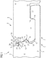
- a first exemplary embodiment of a panel 1 according to the invention is shown in 1 shown. It comprises a panel top 2, a panel bottom 3, a panel core 4 and complementary locking means 5 and 6, which are provided in pairs on opposite panel edges 7 and 8.
- the panel edges in 1 can be thought of as the panel edges that belonged to a panel. In practice, it is quite common to cut through a panel, for example if the panel at the end of a row of panels is too long. Then it is shortened to a suitable length and severed for the purpose. The leftover piece that has been cut off can usually be used to start a new row of panels.
- panel edges shown in sections according to 1 can in principle also be understood as the panel edges of two panels which are not severed.
- the complementary locking means 5 and 6 of the panel are formed as a pair of complementary hook profiles.
- One hook profile is a receiving hook 9 and the hook profile opposite this is a matching locking hook 10 .
- the receiving recess 12 is open to the panel top 2 .
- the locking hook 10 has a locking recess 13 arranged closer to the hull and open to the underside of the panel 3 , and it is provided with a locking shoulder 14 on the hull.
- the locking shoulder 14 fits into the receiving recess 12 of the receiving hook 9 in the vertical joining direction, ie it can be moved down into the receiving recess 12 in a substantially vertical joining direction.
- a gap is provided between the bottom of the locking recess 13 and the top of the hook edge 11 in the locked condition.
- the locking paragraph sits flat on the bottom of the receiving recess 12.
- Retaining surfaces are provided for horizontal locking. They are intended to counteract the movement of locked panels apart in the panel plane, specifically perpendicular to the panel edges.
- One of the holding surfaces 11a is arranged proximally on the edge of the hook. It virtually delimits the receiving recess 12 of the receiving hook 9.
- the complementary holding surface 14a of the locking hook 10 is provided on the locking shoulder 14 proximally.
- the locking hook 10 has a locking contour 15 that has a vertical locking effect and is made in one piece from the material of the panel core 4 .
- the locking contour 15 includes a groove 16 which has an approximately triangular cross section and forms a locking groove.
- a form-fitting contour 17 provided on the receiving hook 9 is also made of the same material and fits together in a form-fitting manner with the locking contour 15 of the locking hook 10 for the purpose of vertical locking.
- the form-fitting contour 17 is designed as a distal, protruding web 18 .
- the web 18 has an approximately triangular cross-section and has a locking surface 19 whose surface normal is directed obliquely to the panel underside 3 , and a free surface 20 whose surface normal is directed obliquely to the panel top 2 .
- the locking surface of the web 18 interacts with a groove wall 21 of the locking groove.
- the receiving hook 9 has a sealing groove 22, the surface of which is formed from the material of the panel core 4.
- a sealing strip 23 is provided above the locking contour 15 of the locking hook 10 , which in turn is formed from the material of the panel core 4 and nestles against the contour of the sealing groove 22 .
- the sealing groove 22 of the receiving hook 9 has a groove edge 24 that protrudes in the direction of the top side of the panel 2 limited, wherein the locking hook 10 has a downwardly open recess 25 for the groove edge 24 is provided.
- the sealing groove 22 has a proximal side 26 and a distal side 27 facing the groove edge 22 and a groove bottom 28.
- the groove bottom has a convexly curved contour, this curvature also extending to the sides 26 and 27.
- the proximal side wall 26 of the sealing groove 22 transitions into an upper abutment surface 29 which is arranged perpendicularly to the top side 2 of the panel.
- the distal side wall 27 has a tangent line 30 as a transition to a concave, round contour which forms the upper side 31 of the edge 24 of the groove.
- the edge of the groove 24 is bounded distally by a lower abutment surface 32 which is arranged perpendicularly relative to the top side 2 of the panel.
- a wedge-shaped cross-sectional area is formed between the upper abutment surface 29 and the tangent line 30 .
- the sealing strip 23 of the locking hook 10 is adapted to the contour of the sealing groove 22 described above and has a quasi-matching wedge-shaped cross section.
- the sealing strip 23 has a proximal strip side 33, which is based on the tangent line 30, and a distal strip side 34, which is adapted to the proximal side wall 26 and also has a transition into an upper abutment surface 35, which interacts with the abutment surface 29.
- the locking hook 10 is provided with a lower abutment surface 36 to match the lower abutment surface 32 of the receiving hook.
- the lower abutment surface 36 is arranged between the downwardly open recess 25 and the locking groove 16 .
- a wedge angle ⁇ of 50° is provided for the sealing strip of the embodiment of 1 .
- This proposed wedge-shaped arrangement is favorable for panels that have a panel core made of swelling material.
- the sealing groove and sealing strip are easier to fit together than, say, a parallel-sided sealing groove/strip because they need a lot of clearance to fit together, but they seal poorly.
- the wedge-shaped design promotes tightness because the side wall 26 of the sealing groove 22 is in contact with the distal strip side 34 of the sealing strip 23 and at the same time the distal side wall 27 of the sealing groove 22 is in contact with the proximal strip side 33 of the sealing strip. Size differences in the cross section of the sealing strip on the one hand and the cross section of the sealing groove on the other hand are less critical than in the case of designs in which the sealing groove/sealing strip provide parallel surface pairs for sealing.
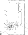
- FIG 2 shows a further development of the panel with an alternative embodiment of the pair of panel edges.
- a broken edge is provided on each of the two hook profiles on the top side 2 of the panel.
- the design is identical to that according to FIG 1 .
- the panel top 2 has an edge break K in the form of a chamfer F1 at the panel edge, which is inclined here at an angle of 35° relative to the panel top.
- the locking hook 10 is provided on the top side 2 of the panel with an edge break K in the form of a chamfer F2, which is designed as a mirror image and to match the chamfer F1 of the receiving hook 9.
- the two chamfers protect the respective panel edge 7 or 8.
- the chamfer reduces the risk of breakage at the concerned panel edge. Together, the chamfers F1 and F2 form a V-joint that is visually appealing and, overall, protects a covering surface because breakage of the panel edges 7 and 8 is rarer and less severe.
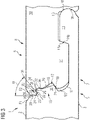
- a distal surface of the hook edge 11 is provided with a male locking contour M, which protrudes in the distal direction.
- a female locking contour W is provided in the locking recess 13 of the locking hook 10 on a proximal surface, which is in contact with the male locking contour and has a vertical locking effect.
- the form-fitting contour 17 of the receiving hook includes a separate vertical locking element 37 which is held captive in a retaining groove 38 in the receiving hook 9 .
- the separate vertical locking element 37 is captively applied in the retaining groove 38 of the receiving hook 9 provided for this purpose, which can be done automatically during the production of the panel, or separate vertical locking elements are enclosed as individual parts in the appropriate number when panels are delivered.
- a vertical locking element must then be inserted manually in the retaining groove 38 of the receiving hook 9 .
- a part 39 of the separate vertical locking element protruding from the retaining groove 38 forms a spring-elastic latching tab. Due to its elastic properties, this can recede during a joining process if a complementary locking hook is pushed against it. When the locking hook is brought to the final locking position, the protruding part of the separate vertical locking element can automatically re-protrude towards its neutral position by means of resilient tension. This more neutral position of the vertical locking element or its spring-elastic locking tab is at the same time also the vertically locking position, which counteracts the hook profiles moving apart in the vertical direction.
- the part of the cross-section of the separate vertical locking element 37, which is held captive in the holding groove 38, has a holding area for this purpose, which has a spine 39 and transverse projections 40, 41 and 42 provided on one side of the spine 39, which, in the applied state, point in the direction of the underside of the panel 3 protrude and reach the opposite groove wall 43 of the retaining groove 38 .
- the captively inserted retaining area of the separate vertical locking element (37) has a certain oversize, which is why the transverse projections 40, 41 and 42 ensure the desired captive hold in the retaining groove 38 with a certain elastic deformation and pretension.
- the spring-elastic locking tab 45 continues on this neck.
- the resilient locking tab 45 has a free end 46 which abuts against the groove wall 21 of the locking groove 16 of the locking hook. It is by means of this contact between the free end 46 and the groove wall 21 that the vertical locking action occurs generated. This is expediently coordinated in such a way that the free end 46 of the locking tab 45 always bears against the groove wall 21 with a residual spring-elastic tension.
- This concept can be designed in such a way that even with a certain amount of wear on the hook profiles, sufficient spring-elastic tension is always retained and no play can form between the locked hook profiles in the vertical direction.
- In the example of 4 shows the free end 46 of the resilient snap-in tab down to the underside of the panel 3.
- the design is according to FIG 4 modified and that is between the edge of the groove 24 and the downwardly open recess 25 some air or a cavity 47 is formed there.
- the intention is to ensure contact of the sealing strip 23 with the groove base 28 of the sealing groove. This is simplified if there is no additional contact between the edge of the groove 24 and the recess 25 by removing material at this point so that the cavity 47 can be formed.
- a distal side face 48 of the locking shoulder 14 is at a distance from a proximal side face 49 of the receiving recess 12. Air should also remain at this point, or a gap 50. The gap at this point also promotes a good fit of the sealing groove 22 and sealing strip 23.
- the same separate vertical locking element 37 can be applied to the locking hook 10 in a captive manner.
- the locking groove 16 must be changed by the vertical locking element 37 to be able to keep captive and in kinematically reversed arrangement, so that the free end 46 of the resilient locking tab 45 is directed upwards to the top side 2 of the panel.
- FIG. 5 Another embodiment according to figure 5 has, like the previous one, again broken edges in the form of chamfers F1 and F2.
- the bevels form a mirror image of each other and form a V-joint.
- a difference from the previous embodiment is the design of the locking heel 14.
- the underside of the locking heel 14 is shown in FIG figure 5 partially cut free, namely a proximal part of the underside is provided with a free cut 51 .
- a distal part of the underside of the locking shoulder 14 remains in contact with the bottom of the receiving recess 12.
- This design creates a certain flexibility of the panel underside 3 Receiving hook 9.
- a dashed line is in figure 5 illustrates an alternative design which provides that when two panel edges (7, 8) are in the locked state, that upper joint which is formed by the upper abutment surface 29 in contact with the upper abutment surface 35 is closed.
- the holding surface 11a to be attributed to the receiving hook 9 is in contact with the holding surface 14a to be attributed to the locking hook 10 .
- the dashed line indicates an elastic bending downwards at the receiving hook by the dimension t.
- the elastic bending causes a permanent pretension within the lock, namely by means of an arrangement of the holding surfaces 11a/14a such that they are inclined by an angle ⁇ with respect to the perpendicular on the panel plane. In particular, this keeps the joint mentioned between the upper abutment surface 29 and the upper counter-abutment surface 35 closed.
- the proposed design of the hook profiles, which generate a permanent bias within the lock and should close the upper joint can of course also as an alternative in each of the embodiments Figures 1 to 4 be provided.
- a second pair of panel edges 60 and 61 of the panel is shown providing a positive tongue and groove connection.
- This pair of panel edges can be combined very well on a square panel with a first pair of edges having the complementary hook profiles according to the invention.
- the panel edges according to 6 do without hook profiles and cannot be locked in one joining movement in a direction perpendicular to the panel plane. Instead, one of the panel edges is provided with a tongue profile 62 and the complementary panel edge has a groove profile 63, so that a joining movement is required which includes a movement component of the panel edges in the panel plane towards one another.
- That panel with tongue profile 62 is moved in a certain skew towards the groove profile 63 of a lying panel and when the tongue is inserted in the groove, the skew panel is then in the same plane of the lying panel swung down.
- the form-fit locking is established by the downward pivoting movement.
- the second pair of edges is designed as in the patent application EP18155583.0 suggested. These panel edges in turn have means for sealing a joint, which are intended to counteract penetration of water to the underside 3 of the panel.
- the tongue profile 62 is provided with a sealing groove 64 and the complementary groove profile 63 has a distally protruding sealing web 65 which fits into the sealing groove 64 .
- the sealing web and sealing groove are each arranged in the material of the panel core 4 . In the present panel core 4, this is a material that can and should swell under moisture.
- the tightness of the panel according to the invention can be improved if it is designed as a square panel and as a second pair of edges with the form-fitting tongue and groove profiles according to FIG EP18155583.0 is executed.
- the tightness of the quadrangular panel can be further improved if a defined common sealing plane 66 is provided.
- the pair of edges with the hook profiles should use the same sealing plane as the second pair of edges, which have the form-fitting tongue and groove profiles (62, 63) according to EP18155583.0 having.
- the second pair of edges provided with the form-fitting tongue and groove profiles should be arranged in relation to the common sealing plane 66 in such a way that an upper side 67 of the sealing web 65 and an upper groove wall 68 of the sealing groove 64, which are in contact with one another as effective sealing surfaces, be arranged at the level of the common sealing plane 66 .
- the groove base 28 of the sealing groove 22, which is in contact with the sealing strip 23, should be arranged so that the deepest point of the groove base 28 is also at the level of the common sealing plane 66, which is through the side by side shown Figures 6 and 7 is illustrated.
- the blocking element is omitted in this illustration for the sake of simplicity; however, it is required for execution 7 the same blocking element 37 is provided as in figs 4 and 5 .
- Fig. 13 again shows a panel 1 according to the invention, which is provided with a separate vertical locking element 69 for the purpose of vertical locking.
- the vertical locking element 69 is provided with a locking tab 70 which protrudes from the retaining groove 38 when two panels are in the locked state.
- the vertical locking element 69 is designed to be spring-elastic on a rear area that extends into the retaining groove 38 .
- This spring-elastic holding area 71 is included in the holding area for the purposes of the invention because it protrudes into the holding groove 38 .
- the function of the spring-elastic holding area 71 is at least mainly to store spring energy and to transmit it as an elastic bias forward into the locking tab 70, which is in the locked state of two panels protrudes from the retaining groove 38, as in 8 to see.
- each embodiment of the Figures 1-7 be provided with the vertical locking element 69 proposed here with the necessary adaptations of the receiving retaining groove 38 as an expedient form-fitting contour 17.
Description
Die Erfindung betrifft ein Paneel umfassend eine Paneeloberseite, eine Paneelunterseite, einen Paneelkern sowie komplementäre Verriegelungsmittel, die paarweise an sich gegenüberliegenden Paneelkanten vorgesehen sind, wobei wenigstens ein Paar Verriegelungsmittel mit komplementären Hakenprofilen versehen ist, nämlich einem Aufnahmehaken und diesem gegenüberliegend einem Arretierhaken, mit der Maßgabe, dass der Aufnahmehaken rumpffern angeordnet einen Hakenrand und rumpfnäher angeordnet eine Aufnahmeaussparung aufweist, wobei die Aufnahmeaussparung zur Paneeloberseite offen ist und wobei der Arretierhaken mit einer rumpfnäher angeordneten und zur Paneelunterseite offenen Arretieraussparung versehen ist und einen rumpffern angeordneten Arretierabsatz aufweist, der in senkrechter Fügerichtung in die Aufnahmeaussparung des Aufnahmehakens passt, wobei der Arretierhaken eine vertikal verriegelnd wirkende Arretierkontur hat und der Aufnahmehaken eine Formschlusskontur aufweist, die zwecks vertikaler Verriegelung formschlüssig mit der Arretierkontur des Arretierhakens zusammenpasst, wobei der Arretierhaken rumpfnäher an seinem Arretierabsatz angeordnet eine horizontal verriegelnde Haltefläche aufweist und der Aufnahmehaken rumpffern in der Aufnahmeaussparung angeordnet mit einer horizontal verriegelnden Haltefläche versehen ist, wobei der Aufnahmehaken mit einer Dichtungsrille versehen ist, welche zur Paneeloberseite offen ist, und wobei der Arretierhaken eine zur Paneelunterseite hervorstehende Dichtungsleiste hat, welche im zusammengefügten Zustand der komplementären Hakenprofile in die Dichtungsrille passt.The invention relates to a panel comprising a top side of a panel, a bottom side of a panel, a panel core and complementary locking means, which are provided in pairs on opposite panel edges, wherein at least one pair of locking means is provided with complementary hook profiles, namely a receiving hook and, opposite this, a locking hook, with the proviso that the receiving hook has a hook edge arranged farther from the fuselage and a receiving recess arranged closer to the fuselage, the receiving recess being open to the top side of the panel and the locking hook being provided with a locking recess arranged closer to the fuselage and open to the underside of the panel and having a locking shoulder arranged farther away from the fuselage, which in the vertical joining direction in the Receiving recess of the receiving hook fits, the locking hook has a locking contour acting vertically locking and the receiving hook has a form-fitting contour, the purpose ver tical locking fits together with the locking contour of the locking hook in a form-fitting manner, wherein the locking hook has a horizontally locking holding surface arranged closer to the torso on its locking heel and the receiving hook is provided with a horizontally locking holding surface arranged in the receiving recess on the torso, wherein the receiving hook is provided with a sealing groove, which is open to the top of the panel, and wherein the locking hook has a sealing strip protruding to the bottom of the panel, which fits into the sealing groove in the assembled state of the complementary hook profiles.
Aus der
Aus der
Die
Der Erfindung liegt die Aufgabe zugrunde, ein verbessertes Paneel vorzuschlagen, mit dem die Dichtungswirkung einfacher zu erzielen ist.The object of the invention is to propose an improved panel with which the sealing effect can be achieved more easily.
Erfindungsgemäß wird die zugrundeliegende Aufgabe dadurch gelöst, dass die Dichtungsrille und die Dichtungsleiste im Bereich des Paneelkerns angeordnet sind, und dass die Oberfläche der Dichtungsrille aus dem Material des Paneelkerns gebildet ist und/oder die Oberfläche der Dichtungsleiste aus diesem Material des Paneelkerns gebildet ist.According to the invention, the underlying object is achieved in that the sealing groove and the sealing strip are arranged in the area of the panel core, and that the surface of the sealing groove is formed from the material of the panel core and/or the surface of the sealing strip is formed from this material of the panel core.
Die Erfindung kehrt davon ab, im Bereich der Hakenprofile den Paneelkern vor Feuchtigkeit abzuschirmen. Stattdessen wird im Material des Paneelkerns eine Dichtungsrille ausgebildet sowie auch eine Dichtungsleiste ausgebildet.The invention moves away from shielding the panel core from moisture in the area of the hook profiles. Instead, a sealing groove is formed in the material of the panel core and a sealing strip is also formed.
Wenn der Paneelkern aus einem Material ist, welches die Eigenschaft hat, Feuchtigkeit aufnehmen zu können und dabei sein Volumen zu vergrößern, wird dies als Quellung bezeichnet. Die Erfindung macht sich diese Eigenschaft zu Nutze und kehrt davon ab, den Paneelkern vor Feuchtigkeit zu schützen.If the core of the panel is made of a material that has the property of being able to absorb moisture and thereby increase its volume, this is referred to as swelling. The invention makes use of this property and moves away from protecting the panel core from moisture.
Stattdessen wird ein Paneelkern benutzt, der eine Quelleigenschaft hat, damit die damit einhergehende Volumenausdehnung ausnutzbar ist, um auf diese Weise eine Dichtungswirkung zu erzielen oder um diese Wirkung zu verstärken.Instead, a panel core is used which has a swelling property so that the associated volume expansion can be exploited in order to achieve a sealing effect in this way or to increase this effect.
Zweckmäßig kann darüber hinaus sein, wenn der Aufnahmehaken mit seiner horizontal verriegelnden Haltefläche in der Aufnahmeaussparung so ausgelegt ist, dass eine permanente Vorspannung gegen die horizontal verriegelnde Haltefläche des Arretierabsatzes erzeugbar ist. Dadurch werden die beiden Paneelkanten elastisch gegeneinander gespannt, was die Fuge an der Paneeloberseite geschlossen hält. Auf diese Weise wird die Abdichtung mittels der Dichtungsrille und Dichtungsleiste begünstigt. Die permanente Vorspannung kann beispielsweise durch eine Gestaltung erzielt werden, die eine elastische Auslenkung an der Paneelunterseite vorsieht bei gleichzeitig geschlossener Fuge an der Paneeloberseite sowie einer ebenen fluchtenden Ausrichtung der Paneeloberseiten der verriegelten Paneele.It can also be expedient if the receiving hook is designed with its horizontally locking holding surface in the receiving recess in such a way that a permanent pretension can be generated against the horizontally locking holding surface of the locking shoulder. As a result, the two panel edges are stretched elastically against each other, which keeps the joint on the top of the panel closed. In this way, sealing by means of the sealing groove and sealing strip is promoted. The permanent prestressing can be achieved, for example, by a design that provides for elastic deflection on the underside of the panel with a simultaneously closed joint on the top side of the panel and a level, flush alignment of the top sides of the panel of the locked panels.
Des Weiteren wird es daher als nützlich angesehen, wenn der Paneelkern ein Material umfasst, das eine Quellung durch Feuchtigkeit begünstigt. Beim gattungsgemäßen Paneel wird versucht, Feuchtigkeit nicht bis zum Paneelkern herankommen zu lassen.Furthermore, it is therefore considered useful if the panel core comprises a material that promotes moisture swelling. In the case of the generic panel, an attempt is made not to allow moisture to reach the panel core.
Allgemein ist es bekannt, für Paneele der gattungsgemäßen Art den Paneelkern aus sogenannten quellvergüteten Platten herzustellen, deren Quellvergütung dazu dient, einer Quellung entgegenzuwirken, z.B. durch Zugabe eines Wachsbestandteils bei der Herstellung der Platte. Von dieser Lehre kehrt die Erfindung ab und schlägt stattdessen vor, auf Maßnahmen zur Quellvergütung zu verzichten oder die Quellvergütung des Materials des Paneelkerns zumindest zu reduzieren.It is generally known to produce the panel core for panels of the generic type from so-called swellable boards, the swelling control of which serves to counteract swelling, for example by adding a wax component during production of the board. The invention departs from this teaching and instead proposes dispensing with measures for swelling control or at least reducing the swelling control of the material of the panel core.
Einfacherweise kann der Paneelkern einen Holzfaserwerkstoff umfassen. Vorzugsweise wird für das erfindungsgemäße Paneel ein Holzfaserwerkstoff mit reduzierter Quellvergütung oder ganz ohne Quellvergütung verwendet. Ein Paneel aus einem quellvergüteten Holzfaserwerkstoff kann beispielsweise wasserabweisende Bestandteile enthalten, wie Wachs. Dies reduziert die Quellung des Holzfaserwerkstoffs je nach Dosierung des wasserabweisenden Bestandteils.The panel core can simply comprise a wood fiber material. A wood fiber material with reduced swelling compensation or no swelling compensation at all is preferably used for the panel according to the invention. A panel made from a swelling-modified wood fiber material can, for example, contain water-repellent components such as wax. This reduces the swelling of the wood fiber material depending on the dosage of the water-repellent component.
Holzfaserwerkstoffe im Sinne dieser Erfindung sind neben hochdichter Holzfaserplatte (HDF), mitteldichter Faserplatte (MDF) und OSB-Platte (engl.: oriented strand board) auch faserhaltige Kompositwerkstoffe wie WPC (engl.: Wood Plastics Composite) oder NFRP (engl.: Natural Fiber Reinforced Plastics).In addition to high-density wood fiber board (HDF), medium-density fiber board (MDF) and OSB board (oriented strand board), wood fiber materials within the meaning of this invention also include fiber-containing composite materials such as WPC (wood plastics composite) or NFRP (natural Fiber Reinforced Plastics).
Erfindungsgemäß wird die quellende Eigenschaft des Paneelkerns ausgenutzt, um zur Abdichtung verriegelter Paneelkanten beizutragen. Durch die vorgeschlagene Maßnahme bleiben tiefere Bereiche des Paneelkerns überraschenderweise frei von Feuchtigkeit, obwohl wasserabweisende Bestandteile im Holzfaserwerkstoff weggelassen oder mindestens reduziert werden. Überraschend hat sich gezeigt, unter das Niveau von Dichtungsrille und Dichtungsleiste gelangt nahezu keine Feuchtigkeit mehr. Diejenigen Bereiche der Hakenprofile bleiben trocken, welche den Zusammenhalt verriegelter Paneelkanten bewirken, nämlich die Arretierkontur des Arretierhakens sowie die Formschlusskontur des Aufnahmehakens. Entsprechende Tests im Bereich von T-Fugen haben ergeben, dass Wasser, im Bereich einer T-Fuge auf einer Bodenoberfläche, die aus erfindungsgemäßen Paneelen zusammengefügt ist, auch nach langer Dauer nicht bis zur Unterseite des Bodenbelags durchsickern kann.According to the invention, the swelling property of the panel core is used to contribute to the sealing of interlocked panel edges. As a result of the proposed measure, deeper areas of the panel core surprisingly remain free of moisture, although water-repellent components in the wood fiber material are omitted or at least reduced. Surprisingly, it has been shown that almost no moisture gets below the level of the sealing groove and sealing strip. Those areas of the hook profiles that bring about the cohesion of locked panel edges remain dry, namely the locking contour of the locking hook and the form-fitting contour of the receiving hook. Corresponding tests in the area of T-joints have shown that water, in the area of a T-joint on a floor surface which is joined together from panels according to the invention, cannot seep through to the underside of the floor covering, even after a long period of time.
Zweckmäßig ist die Dichtungsleiste relativ zur Dichtungsrille ohne Übermaß gestaltet, damit sich diese leicht ineinanderfügen lassen.The sealing strip is expediently designed without excess relative to the sealing groove so that they can be easily fitted together.
Hilfreich ist es, wenn die Dichtungsrille mit einander gegenüberliegenden Seitenwänden versehen ist, einen Rillengrund hat und distal von einem in Richtung der Paneeloberseite vorstehenden Rillenrand begrenzt ist, wobei die Seitenwände relativ zueinander eine keilförmige Anordnung einnehmen, wobei der Keilwinkel zur Paneeloberseite offen ist, und wobei der Keilwinkel im Bereich von 30° bis 70° liegt, bevorzugt im Bereich von 40° bis 60° und besonders bevorzugt bei 45° bis 55° liegt.It is helpful if the sealing groove is provided with opposite side walls, has a groove base and is limited distally by a groove edge protruding in the direction of the top side of the panel, the side walls occupying a wedge-shaped arrangement relative to one another, the wedge angle to the top side of the panel being open, and where the wedge angle is in the range from 30° to 70°, preferably in the range from 40° to 60° and particularly preferably at 45° to 55°.
Wie sich herausgestellt hat ist es besonders hilfreich die vorgeschlagene keilförmige Anordnung der Seitenwände so vorzusehen, dass der Raum zwischen den Seitenwänden zum Rillengrund der Dichtungsrille enger wird. Des Weiteren hilft es, wenn dann auch die Dichtungsleiste Außenflächen hat, welche an die keilförmige Anordnung der Seitenwände der Dichtungsrille angepasst sind.As has been found, it is particularly helpful to provide the proposed wedge-shaped arrangement of the side walls in such a way that the space between the side walls becomes narrower towards the bottom of the sealing groove. Furthermore, it helps if the sealing strip also has outer surfaces which are adapted to the wedge-shaped arrangement of the side walls of the sealing groove.
Des Weiteren hilft es, dass der Querschnitt der Dichtungsrille zwischen den Seitenwänden und dem Rillengrund jeweils einen runden Übergang aufweist. (z.B. Radius) ... im Unterscheid zum SdT der Fig. 5c aus
Ebenfalls nützlich ist zwischen der distalen Seitenwand und dem Rillenrand im Querschnitt ein runder Übergang vorgesehen.A round transition is also useful in cross-section between the distal side wall and the edge of the groove.
An die proximale Seitenwand der Dichtungsrille schließt sich nach oben eine Anstoßfläche an, die vorzugsweise senkrecht zur Paneeloberseite angeordnet ist.At the top of the proximal side wall of the sealing groove is an abutment surface, which is preferably arranged perpendicularly to the top side of the panel.
Die distale Fläche des Rillenrandes ist vorzugsweise senkrecht zur Paneeloberseite angeordnet.The distal surface of the groove edge is preferably perpendicular to the panel top.
Zweckmäßig ist am Arretierhaken proximal zur Dichtungsleiste eine nach unten in Richtung der Paneelunterseite offene Aussparung vorgesehen. In dieser nach unten offenen Aussparung findet der nach oben vorstehende Rillenrand des Aufnahmehakens Platz. Vorzugsweise ist der Querschnitt der Aussparung größer als der Querschnitt des Rillenrandes, und zwar so dass im zusammengefügten Zustand zwischen einer Oberseite des Rillenrandes und dem Grund der Aussparung ein Hohlraum gebildet ist.Appropriately, a recess open downwards in the direction of the underside of the panel is provided on the locking hook proximal to the sealing strip. In this recess, which is open at the bottom, there is room for the grooved edge of the receiving hook that protrudes upwards. The cross section of the recess is preferably larger than the cross section of the groove edge, specifically so that in the assembled state a cavity is formed between an upper side of the groove edge and the base of the recess.
Als nützlich hat sich herausgestellt, wenn die Dichtungsleiste an die Querschnittsform der Dichtungsrille angepasst ist. Auf diese Weise und durch Vermeidung von eckigen Konturen kann von einer Gleichmäßigkeit der Quellung profitiert werden.It has turned out to be useful if the sealing strip is adapted to the cross-sectional shape of the sealing groove. In this way, and by avoiding angular contours, you can benefit from an even swelling.
Ein weiterer Nutzen wird darin gesehen, dass ein separates Vertikalsperrelement vorgesehen ist, und dass das separate Vertikalsperrelement vor einer Verriegelung der Paneelkanten entweder als Bestandteil der Arretierkontur des Arretierhakens vorgesehen ist oder als Bestandteil der Formschlusskontur des Aufnahmehakens vorgesehen ist.A further benefit is seen in the fact that a separate vertical locking element is provided and that the separate vertical locking element is provided either as part of the locking contour of the locking hook or as part of the form-fitting contour of the receiving hook before locking the panel edges.
Einfacherweise weist die Arretierkontur des Arretierhakens eine Nut für das separate Vertikalsperrelement auf, wobei die Formschlusskontur des Aufnahmehakens ebenfalls eine Nut für das separate Vertikalsperrelement aufweist.The locking contour of the locking hook simply has a groove for the separate vertical locking element, with the form-fitting contour of the receiving hook also having a groove for the separate vertical locking element.
Zweckmäßig ist entweder die Nut im Aufnahmehaken oder die Nut im Arretierhaken als Haltenut hergerichtet, um das separate Vertikalsperrelement vor einer Verriegelung der Paneelkanten verliersicher halten zu können, wobei ein aus der verliersicher haltenden Nut hervorstehender Teil des separaten Vertikalsperrelements während eines Fügevorgangs in Eingriff zu bringen ist mit der jeweils anderen Nut. Das separate Vertikalsperrelement kann demzufolge verliersicher in der Nut des Arretierhakens appliziert sein. Soll es hingegen in der Nut des Aufnahmehakens verliersicher gehalten sein, dann muss es ggf. im Sinne einer kinematischen Umkehr in geänderter Orientierung appliziert werden, um die Funktion zu gewährleisten.Expediently, either the groove in the receiving hook or the groove in the locking hook is designed as a holding groove in order to be able to hold the separate vertical locking element in a captive manner before locking the panel edges, with a part of the separate vertical locking element protruding from the captive groove being engaged during a joining process with the other groove. The separate vertical locking element can therefore be captively applied in the groove of the locking hook. On the other hand, if it is to be held captive in the groove of the receiving hook, then it may have to be applied in a changed orientation in the sense of a kinematic reversal in order to ensure the function.
Als nützlich herausgestellt hat sich, dass relativ zum Paneelkern sowohl die Nut im Aufnahmehaken als auch die Nut im Arretierhaken in distaler Richtung offen ist.It has turned out to be useful that both the groove in the receiving hook and the groove in the locking hook are open in the distal direction relative to the panel core.
Einfacherweise hat das separate Vertikalsperrelement einen Haltebereich, der zur verliersicheren Applikation des Vertikalsperrelements mittels einer der Nuten vorgesehen ist, und dass ein hervorstehender Teil des Vertikalsperrelements mit einer Rastlasche versehen ist. D. h. der Haltebereich des Vertikalsperrelements wirkt mit der Nut zusammen, in welcher das Vertikalsperrelement verliersicher gehalten werden soll.The separate vertical locking element simply has a holding area, which is provided for captive application of the vertical locking element by means of one of the grooves, and that a protruding part of the vertical locking element is provided with a locking tab. i.e. the holding area of the vertical locking element interacts with the groove in which the vertical locking element is to be held captive.
Der Haltebereich und/oder die Rastlasche des separaten Vertikalsperrelements kann federnd ausgebildet sein, nämlich zwecks automatischer Verrastbarkeit der Rastlasche in einer Nut während eines Fügevorgangs komplementärer Hakenprofile. Durch diese Maßnahme ist eine automatische Verrastung ermöglicht, so dass die Herstellung der vertikalen Verriegelung automatisch erfolgt.The holding area and/or the snap-in tab of the separate vertical locking element can be designed to be resilient, namely for the purpose of automatic latchability of the snap-in tab in a groove during a joining process of complementary hook profiles. This measure enables automatic latching, so that the vertical locking takes place automatically.
Zweckmäßig ist zumindest eine mit Hakenprofil versehene Paneelkante an der Paneeloberseite mit einer Kantenbrechung versehen. Falls beide Paneelkanten mit komplementären Verriegelungsmitteln eine Kantenbrechung haben lässt sich so im zusammengefügten Zustand von Paneelen eine Belagsoberfläche mit optisch ansprechender Fuge erzeugen. Die Fuge kann beispielsweise eine V-Fuge sein, die aus zwei gegeneinander stehenden Fasen gebildet ist. Eine Fuge hat den Vorteil, die Paneelkanten zu schützen, insbesondere eine V-Fuge, beziehungsweise die jeweilige Fase bietet guten Schutz für die jeweilige Paneelkante.At least one panel edge provided with a hook profile is expediently provided with a broken edge on the top side of the panel. If both panel edges with complementary locking means have a broken edge, a covering surface with a visually appealing joint can be produced when the panels are in the assembled state. The joint can be a V-joint, for example, which is formed from two opposing bevels. A joint has the advantage of protecting the panel edges, especially a V-joint, or the respective chamfer offers good protection for the respective panel edge.
Eine Kantenbrechung kann mit einer Beschichtung versehen sein. Zweckmäßig ist eine solche Beschichtung vorgesehen, welche an der Oberfläche der Kantenbrechung einer Aufnahme von Feuchtigkeit in das Material des Paneelkerns entgegenwirkt. Hierfür ist jedes geeignete abdichtende Beschichtungsmaterial verwendbar, beispielsweise Lack oder Folie. Die erfindungsgemäße Ausnutzung der Quelleigenschaft des Materials des Paneelkerns soll erst an jenen unterhalb einer Kantenbrechung befindlichen Flächen der Paneelkante beginnen und ihre Wirkung dort entfalten, wo eine Abdichtung durch Quellung von Material benötigt und gewünscht wird.An edge break can be provided with a coating. Such a coating is expediently provided which counteracts the absorption of moisture into the material of the panel core on the surface of the broken edge. Any suitable sealing coating material can be used for this purpose, for example paint or foil. The utilization of the swelling property of the material of the panel core according to the invention should only begin on those areas of the panel edge located below an edge break and develop its effect there where sealing by swelling of material is required and desired.
Nachstehend ist die Erfindung in einer Zeichnung beispielhaft veranschaulicht und detailliert beschrieben. Es zeigen:
- Fig. 1
- ein erstes Paar Paneelkanten des erfindungsgemäßen Paneels im Querschnitt,
- Fig. 2
- eine Weiterbildung des Paneels mit alternativer Ausführungsform des Paneelkantenpaares gemäß
Fig. 1 , - Fig. 3
- eine Weiterbildung des Paneels mit alternativer Ausführungsform des Paneelkantenpaares gemäß
Fig. 2 , - Fig. 4
- eine Ausführungsform des Paneels mit einem ersten Paar Paneelkanten mit separatem Vertikalsperrelement,
- Fig. 5
- eine weitere Ausführungsform des Paneels mit einem ersten Paar Paneelkanten mit separatem Vertikalsperrelement,
- Fig. 6
- ein zweites Paar Paneelkanten des Paneels mit formschlüssiger Nut- und Federverbindung sowie mit Dichtungssteg und Dichtungsnut gemäß der Anmeldung
EP 18155583.0 - Fig. 7
- das erste Paar Paneelkanten gemäß
Fig. 5 mit leerer Nut für ein Vertikalsperrelement, - Fig. 8
- ein weiteres Ausführungsbeispiel mit einem alternativen separaten Vertikalsperrelement.
- 1
- a first pair of panel edges of the panel according to the invention in cross section,
- 2
- a further development of the panel with an alternative embodiment of the pair of panel edges according to FIG
1 , - 3
- a further development of the panel with alternative Embodiment of the pair of panel edges according to
2 , - 4
- an embodiment of the panel with a first pair of panel edges with a separate vertical locking element,
- figure 5
- a further embodiment of the panel with a first pair of panel edges with a separate vertical locking element,
- 6
- a second pair of panel edges of the panel with a form-fitting tongue and groove connection and with a sealing web and sealing groove according to the application
EP18155583.0 - Figure 7
- the first pair of panel edges as per
figure 5 with an empty groove for a vertical locking element, - 8
- another embodiment with an alternative separate vertical locking element.
Ein erstes Ausführungsbeispiel eines erfindungsgemäßen Paneels 1 ist in
Selbstverständlich können die ausschnittsweise dargestellten Paneelkanten gemäß
Gemäß dem ersten Ausführungsbeispiel sind die komplementären Verriegelungsmittel 5 und 6 des Paneels als ein Paar komplementärer Hakenprofile ausgebildet. Ein Hakenprofil ist ein Aufnahmehaken 9 und das diesem gegenüberliegende Hakenprofil ist ein dazu passender Arretierhaken 10. Dabei hat der Aufnahmehaken 9 rumpffern angeordnet einen Hakenrand 11 und rumpfnäher weist er eine Aufnahmeaussparung 12 auf. Die Aufnahmeaussparung 12 ist zur Paneeloberseite 2 offen. Der Arretierhaken 10 hat rumpfnäher angeordnet und zur Paneelunterseite 3 offen eine Arretieraussparung 13 und rumpffern ist er mit einem Arretierabsatz 14 versehen. Der Arretierabsatz 14 passt in senkrechter Fügerichtung in die Aufnahmeaussparung 12 des Aufnahmehakens 9, d. h. er lässt in wesentlich senkrechter Fügerichtung in die Aufnahmeaussparung 12 hinab bewegen. Zwischen dem Grund der Arretieraussparung 13 und dem Top des Hakenrandes 11 ist im verriegelten Zustand eine Lücke vorgesehen. Der Arretierabsatz sitzt flächig auf dem Grund der Aufnahmeaussparung 12. Für die horizontale Verriegelung sind Halteflächen vorgesehen. Sie sollen einem Auseinanderbewegen verriegelter Paneele in der Paneelebene und zwar senkrecht zu den Paneelkanten entgegenwirken. Eine der Halteflächen 11a ist am Hakenrand proximal angeordnet. Sie begrenzt quasi die Aufnahmeaussparung 12 des Aufnahmehakens 9. Die komplementäre Haltefläche 14a des Arretierhakens 10 ist am Arretierabsatz 14 proximal vorgesehen.According to the first embodiment, the complementary locking means 5 and 6 of the panel are formed as a pair of complementary hook profiles. One hook profile is a receiving
Des Weiteren hat der Arretierhaken 10 eine vertikal verriegelnd wirkende Arretierkontur 15, die einstückig aus dem Material des Paneelkerns 4 besteht. Die Arretierkontur 15 umfasst eine Nut 16, die einen etwa dreieckigen Querschnitt hat und eine Arretiernut bildet. Aus demselben Material ist auch eine am Aufnahmehaken 9 vorgesehene Formschlusskontur 17, welche zwecks vertikaler Verriegelung formschlüssig mit der Arretierkontur 15 des Arretierhakens 10 zusammenpasst. Die Formschlusskontur 17 ist als ein distaler hervorstehender Steg 18 ausgebildet. Der Steg 18 hat einen etwa dreieckigen Querschnitt und weist eine Verriegelungsfläche 19 auf, deren Flächennormale schräg zur Paneelunterseite 3 gerichtet ist, sowie eine Freifläche 20, deren Flächennormale schräg zur Paneeloberseite 2 gerichtet ist. Die Verriegelungsfläche des Steges 18 wirkt zusammen mit einer Nutwand 21 der Arretiernut.Furthermore, the locking
Oberhalb der Formschlusskontur 17 hat der Aufnahmehaken 9 eine Dichtungsrille 22, deren Oberfläche aus dem Material des Paneelkerns 4 gebildet ist.Above the form-fitting
Passend dazu ist oberhalb der Arretierkontur 15 des Arretierhakens 10 eine Dichtungsleiste 23 vorgesehen, die ihrerseits aus dem Material des Paneelkerns 4 gebildet ist und sich an die Kontur der Dichtungsrille 22 anschmiegt.Matching this, a sealing
Die Dichtungsrille 22 des Aufnahmehakens 9 ist von einem in Richtung der Paneeloberseite 2 vorstehenden Rillenrand 24 begrenzt, wobei am Arretierhaken 10 eine nach unten offenen Aussparung 25 für den Rillenrand 24 vorgesehen ist. Die Dichtungsrille 22 hat eine proximale Seite 26 sowie dem Rillenrand 22 zugewandt eine distale Seite 27 sowie einen Rillengrund 28. Der Rillengrund hat eine konvex gekrümmte Kontur, wobei sich diese Krümmung auch zu den Seiten 26 und 27 erstreckt.The sealing
Die proximale Seitenwand 26 der Dichtungsrille 22 geht über in eine obere Anstoßfläche 29, die senkrecht zur Paneeloberseite 2 angeordnet ist. Die distale Seitenwand 27 hat eine Tangentenlinie 30 als Übergang in eine konkav runde Kontur, welche die Oberseite 31 des Rillenrandes 24 bildet. Der Rillenrand 24 ist distal von einer unteren Anstoßfläche 32 begrenzt, die relativ zur Paneeloberseite 2 senkrecht angeordnet ist.The
Zwischen der oberen Anstoßfläche 29 und der Tangentenlinie 30 ist ein keilförmiger Querschnittsbereich gebildet.A wedge-shaped cross-sectional area is formed between the
Die Dichtungsleiste 23 des Arretierhakens 10 ist an die oben beschriebene Kontur der Dichtungsrille 22 angepasst und hat quasi einen passend keilförmigen Querschnitt. Die Dichtungsleiste 23 hat eine proximale Leistenseite 33, die sich an der Tangentenlinie 30 orientiert sowie eine distale Leistenseite 34, welche an die proximale Seitenwand 26 angepasst ist und gleichfalls einen Übergang in eine obere Gegenstoßfläche 35 hat, welche mit der Anstoßfläche 29 zusammenwirkt.The sealing
Passend zur unteren Anstoßfläche 32 des Aufnahmehakens ist der Arretierhaken 10 mit einer unteren Gegenstoßfläche 36 versehen. Die untere Gegenstoßfläche 36 ist zwischen der nach unten offenen Aussparung 25 und der Arretiernut 16 angeordnet.The locking
Für die Dichtungsleiste des Ausführungsbeispiels der
Mit
Eine weitere Ausführungsform des Paneels ist in
Ein aus der Haltenut 38 hervorstehendes Teil 39 des separaten Vertikalsperrelements bildet eine federelastische Rastlasche. Diese kann während eines Fügevorgangs aufgrund ihrer elastischen Eigenschaft zurückweichen, wenn ein komplementärer Arretierhaken dagegen gestoßen wird. Wenn der Arretierhaken bis in die endgültige Verriegelungsposition gebracht wird, kann das hervorstehende Teil des separaten Vertikalsperrelements automatisch mittels federelastischer Spannung in Richtung seiner neutralen Position wieder hervortreten. Diese neutralere Position des Vertikalsperrelements beziehungsweise seiner federelastischen Rastlasche ist gleichzeitig auch die vertikal verriegelnde Position, welche einem Auseinanderbewegen der Hakenprofile in vertikaler Richtung entgegenwirkt.A
Das Teil des Querschnitts des separaten Vertikalsperrelements 37, das verliersicher in der Haltenut 38 gehalten ist, weist dafür einen Haltebereich auf, der einen Rücken 39 hat sowie einseitig am Rücken 39 vorgesehene Quervorsprünge 40, 41 und 42, die im applizierten Zustand in Richtung der Paneelunterseite 3 hervortreten und bis zur gegenüberlegenden Nutwand 43 der Haltenut 38 reichen. Im Verhältnis zur Weite der Haltenut hat der verliersicher eingefügte Haltebereich des separaten Vertikalsperrelements (37) ein gewisses Übermaß, weswegen die Quervorsprünge 40, 41 und 42 mit gewisser elastischer Verformung und Vorspannung für den gewünschten verliersicheren Halt in der Haltenut 38 sorgen. Gegenüberliegend zu den drei Quervorsprüngen 40, 41 und 42 setzt an einem Ende des Rückens 39 ein Hals 44 an. An diesem Hals wiederum setzt sich die federelastische Rastlasche 45 fort. Die federelastische Rastlasche 45 hat ein freies Ende 46, welches gegen die Nutwand 21 der Arretiernut 16 des Arretierhakens stößt. Mittels dieses Kontaktes zwischen dem freien Ende 46 und der Nutwand 21 wird die vertikale Verriegelungswirkung erzeugt. Zweckmäßig ist dies so aufeinander abgestimmt, damit das freie Ende 46 der Rastlasche 45 stets mit einem Rest an federelastischer Spannung an der Nutwand 21 anliegt. Dieses Konzept kann so ausgelegt sein, dass selbst bei einem gewissen Verschleiß der Hakenprofile stets genügend federelastische Spannung erhalten bleibt und sich in vertikaler Richtung kein Spiel zwischen den verriegelten Hakenprofilen ausbilden kann. Im Beispiel der
Im Bereich der Dichtungsrille 22 des Aufnahmehakens und der Dichtungsleiste 23 des Arretierhakens ist die Gestaltung gemäß
Eine distale Seitenfläche 48 des Arretierabsatzes 14 hat im zusammengefügten Zustand der Hakenprofile einen Abstand zu einer proximalen Seitenfläche 49 der Aufnahmeaussparung 12. Auch an dieser Stelle soll Luft bleiben, beziehungsweise eine Lücke 50. Die Lücke an dieser Stelle begünstigt ebenfalls ein gutes Ineinanderpassen von Dichtungsrille 22 und Dichtungsleiste 23.When the hook profiles are in the assembled state, a distal side face 48 of the locking
Der Vollständigkeit halber sei erwähnt, dass bei einer anderen Ausführung dasselbe separate Vertikalsperrelement 37 verliersicher am Arretierhaken 10 appliziert werden kann. Dafür muss die Arretiernut 16 geändert werden um das Vertikalsperrelement 37 verliersicher halten zu können und zwar in kinematisch umgekehrter Anordnung, so dass das freie Ende 46 der federelastischen Rastlasche 45 nach oben zur Paneeloberseite 2 gerichtet ist.For the sake of completeness, it should be mentioned that in another embodiment, the same separate
Ein weiteres Ausführungsbeispiel gemäß
Mittels einer gestrichelten Linie ist in
Dabei ist gleichzeitig die dem Aufnahmehaken 9 zuzurechnende Haltefläche 11a in Kontakt mit der dem Arretierhaken 10 zuzurechnenden Haltefläche 14a. Die gestrichelte Linie deutet eine elastische Biegung am Aufnahmehaken nach unten um das Maß t an. Die elastische Biegung bewirkt eine permanente Vorspannung innerhalb der Verriegelung, nämlich mittels einer Anordnung der Halteflächen 11a/14a so, dass sie gegenüber dem Lot auf der Paneelebene um einen Winkel β geneigt sind. Dies hält insbesondere die erwähnte Fuge zwischen oberer Anstoßfläche 29 und oberer Gegenstoßfläche 35 geschlossen. Die hier vorgeschlagene Ausbildung der Hakenprofile, welche eine permanente Vorspannung innerhalb der Verriegelung erzeugen und die obere Fuge schließen soll kann selbstverständlich auch als Alternative bei jedem der Ausführungsbeispiele der
Anhand von
Das zweite Kantenpaar ist so gestaltet, wie in der Patentanmeldung
Die Dichtheit des erfindungsgemäßen Paneels kann verbessert werden, wenn es als viereckiges Paneel ausgeführt wird und als zweites Kantenpaar mit den formschlüssigen Nut- und Federprofilen gemäß
Darüber hinaus wurde gefunden, dass die Dichtheit des viereckigen Paneels noch weiter verbessert werden kann, wenn eine definierte gemeinsame Dichtungsebene 66 vorgesehen wird. Es soll das Kantenpaar mit den Hakenprofilen dieselbe Dichtungsebene nutzen, wie auch das zweite Kantenpaar, welches die formschlüssigen Nut- und Federprofile (62, 63) gemäß
Zu dem Zweck wird vorgeschlagen, es soll dasjenige mit den formschlüssigen Nut- und Federprofilen versehene zweite Kantenpaar in Bezug auf die gemeinsame Dichtungsebene 66 so angeordnet sein, dass eine Oberseite 67 des Dichtungssteges 65 sowie eine obere Nutwand 68 der Dichtungsnut 64, welche als wirksame dichtende Flächen miteinander in Berührung stehen, auf dem Niveau der gemeinsamen Dichtungsebene 66 angeordnet sein.For this purpose, it is proposed that the second pair of edges provided with the form-fitting tongue and groove profiles should be arranged in relation to the
In Bezug auf das Kantenpaar mit den Hakenprofilen, wie in
Auf diese Weise ist erreicht, dass dichtend in Berührung stehende Flächen beider Kantenpaare, weil sie in derselben Dichtungsebene 66 angeordnet sind, auch in den Ecken der Paneele keine Dichtheitslücken entstehen lassen.In this way it is achieved that sealingly contacting surfaces of both edge pairs, because they are arranged in the same sealing
- 11
- Paneelpanel
- 22
- Paneeloberseitepanel top
- 33
- Paneelunterseitepanel underside
- 44
- Paneelkernpanel core
- 55
- Verriegelungsmittellocking means
- 66
- Verriegelungsmittellocking means
- 77
- Paneelkantepanel edge
- 88th
- Paneelkantepanel edge
- 99
- Aufnahmehakenpick-up hook
- 1010
- Arretierhakenlocking hook
- 1111
- Hakenrandhook edge
- 11a11a
- horizontal verriegelnde Halteflächehorizontal locking holding surface
- 1212
- Aufnahmeaussparungrecording recess
- 1313
- Arretieraussparunglocking recess
- 1414
- Arretierabsatzlocking heel
- 14a14a
- horizontal verriegelnde Halteflächehorizontal locking holding surface
- 1515
- Arretierkonturlocking contour
- 1616
- Arretiernutlocking groove
- 1717
- Formschlusskonturform-fitting contour
- 1818
- Stegweb
- 1919
- Verriegelungsflächelocking surface
- 2020
- Freiflächeopen space
- 2121
- Nutwand (Arretiernut)groove wall (locking groove)
- 2222
- Dichtungsrillesealing groove
- 2323
- Dichtungsleistesealing strip
- 2424
- Rillenrandgroove edge
- 2525
- Aussparungrecess
- 2626
- proximale Seitenwandproximal sidewall
- 2727
- distale Seitenwanddistal sidewall
- 2828
- Rillengrundgroove bottom
- 2929
- obere Anstoßflächeupper impact surface
- 3030
- Tangentenlinietangent line
- 3131
- Oberseite (Rillenrand)top (groove edge)
- 3232
- unter Anstoßflächeunder impact surface
- 3333
- proximale Leistenseiteproximal groin side
- 3434
- distale Leistenseitedistal inguinal side
- 3535
- obere Gegenstoßflächeupper counterattack surface
- 3636
- untere Gegenstoßflächelower counter surface
- 3737
- separates Vertikalsperrelementseparate vertical locking element
- 3838
- Nutgroove
- 3939
- Rückenthe back
- 4040
- Quervorsprungtransverse projection
- 4141
- Quervorsprungtransverse projection
- 4242
- Quervorsprungtransverse projection
- 4343
- Nutwandgroove wall
- 4444
- Halsthroat
- 4545
- federelastische Rastlaschespring-elastic latch
- 4646
- freies Endefree end
- 4747
- Hohlraumcavity
- 4848
- distale Seitenflächedistal side surface
- 4949
- proximale Seitenflächeproximal side surface
- 5050
- Lückegap
- 5151
- Freischnittfree cut
- 5252
- Spaltgap
- 6060
- Paneelkantepanel edge
- 6161
- Paneelkantepanel edge
- 6262
- Federprofilspring profile
- 6363
- Nutprofilgroove profile
- 6464
- Dichtungsnutseal groove
- 6565
- Dichtungsstegsealing bar
- 6666
- gemeinsame Dichtungsebenecommon sealing plane
- 6767
- Oberseite (Dichtungssteg)top (sealing ridge)
- 6868
- obere Nutwand (Dichtungsnut)upper groove wall (seal groove)
- 6969
- separates Vertikalsperrelementseparate vertical locking element
- 7070
- Rastlaschelocking tab
- 7171
- federelastischer Haltebereichspring-elastic holding area
- F1F1
- Fasechamfer
- F2F2
- Fasechamfer
- MM
- männliche Rastkonturmale resting contour
- WW
- weibliche Rastkonturfemale latch contour
- αa
- Keilwinkelwedge angle
- ββ
- Winkelangle
Claims (14)
- Panel (1) comprising a panel top side (2), a panel underside (3), a panel core (4) and complementary locking means (5, 6) provided in pair-wise relationship at mutually opposite panel edges (7, 8), wherein at least one pair of locking means is provided with complementary hook profiles, namely a receiving hook (9) and an arresting hook (10) opposite thereto, with the proviso that the receiving hook (9) has arranged remote from the main body a hook edge (11) and arranged closer to the main body a receiving recess (12), wherein the receiving recess (12) is open towards the panel top side (2) and wherein the arresting hook (10) is provided with an arresting recess (13) arranged closer to the main body and open towards the panel underside (3) and an arresting shoulder (14) which is arranged remote from the main body and which fits in the perpendicular joining direction into the receiving recess (12) of the receiving hook (9), wherein the arresting hook (10) has an arresting contour (15) with a vertical locking action and the receiving hook (9) has a positively locking contour (17) which for the purposes of vertical locking fits together in positively locking relationship with the arresting contour (15) of the arresting hook (10), wherein the arresting hook (10) has a horizontally locking holding surface (14a) arranged closer to the main body at its arresting shoulder (14) and the receiving hook (9) is provided with a horizontally locking holding surface (11a) arranged remote from the main body in the receiving recess (12), wherein the receiving hook (9) is provided with a sealing groove (22) open towards the panel top side (2) and wherein the arresting hook (10) has a sealing strip (23) which projects with respect to the panel underside (3) and which fits into the sealing groove (22) in the assembled state of the complementary hook profiles, characterised in that the sealing groove (22) and the sealing strip (23) are arranged in the region of the panel core (4) and the surface of the sealing groove (22) is formed from the material of the panel core (4) and/or the surface of the sealing strip (23) is formed from the material of the panel core (4), wherein the panel core has a swelling property.
- Panel according to claim 1, characterised in that the panel core (4) is made of a material which has the property of being able to absorb moisture and in so doing increase its volume.
- Panel according to claim 1 or claim 2 characterised in that the panel core (4) includes a wood fibre material.
- Panel according to one of claims 1 to 3 characterised in that the sealing groove (22) is provided with mutually opposite side walls (26, 27), has a groove bottom (28) and is delimited distally by a groove edge (24) projecting in the direction of the panel top side (2), wherein the side walls (26, 27) assume relative to each other a wedge-shaped arrangement, wherein the wedge angle (α) is open towards the panel top side (2) and wherein the wedge angle (α) is in the range of 30° to 70°, preferably in the range of 40° to 60° and particularly preferably at 45° to 55°.
- Panel according to claim 4 characterised in that the cross-section of the sealing groove (22) has a respective round transition between the side walls (26, 27) and the groove bottom (28).
- Panel according to claim 5 characterised in that there is provided a round transition between the distal side wall (27) and the groove edge (24) in the cross-section thereof.
- Panel according to one of claims 1 to 6 characterised in that the sealing strip (23) is adapted to the cross-sectional shape of the sealing groove (22).
- Panel according to one of claims 1 to 7 characterised in that there is provided a separate vertical locking element (37) and the separate vertical locking element (37, 69) prior to locking of the panel edges (7, 8) is either integrated as a constituent part of the arresting contour (15) of the arresting hook (10) or is integrated as a constituent part of the positively locking contour (17) of the receiving hook (9).
- Panel according to claim 8 characterised in that the arresting contour (15) of the arresting hook (10) has a holding groove (38) for the separate vertical locking element (37, 69) and the positively locking contour of the receiving hook also has a holding groove (38) for the separate vertical locking element (37, 69).
- Panel according to claim 9 characterised in that either the holding groove (38) in the receiving hook (9) or the groove (16) in the arresting hook (10) is arranged as a holding groove in order to be able to captively hold the separate vertical locking element (37, 69) prior to locking of the panel edges (7, 8), wherein a part projecting from the holding groove (38) of the separate vertical locking element (37) is to be brought into engagement with the respective other groove during a joining operation.
- Panel according to claim 9 or claim 10 characterised in that both the holding groove (38) in the receiving hook (9) and also the groove (16) in the arresting hook (10) is open relative to the panel core (4) in the distal direction.
- Panel according to one of claims 9 to 11 characterised in that the separate vertical locking element (37, 69) has a holding region which is provided for captive application of the vertical locking element by means of one of the grooves and a projecting part of the vertical locking element is provided with a retaining latch (45, 70).
- Panel according to claim 12 characterised in that the holding region and/or the retaining latch (45, 70) of the separate vertical locking element (37, 69) is of a resilient configuration for the purposes of automatic latchability of the retaining latch (45, 70) in a groove (16) during a joining operation of complementary hook profiles.
- Panel according to one of claims 1 to 13 characterised in that at least one panel edge (7, 8) which is provided with hook profiles is provided with an edge break (F1, F2) at the panel top side (2).
Priority Applications (4)
| Application Number | Priority Date | Filing Date | Title |
|---|---|---|---|
| EP18178064.4A EP3581732B1 (en) | 2018-06-15 | 2018-06-15 | Panel with sealing crease and sealing ridge |
| CN201980040330.4A CN112334625B (en) | 2018-06-15 | 2019-06-13 | Panel |
| PCT/EP2019/065465 WO2019238811A1 (en) | 2018-06-15 | 2019-06-13 | Panel |
| US17/252,569 US11608646B2 (en) | 2018-06-15 | 2019-06-13 | Panel |
Applications Claiming Priority (1)
| Application Number | Priority Date | Filing Date | Title |
|---|---|---|---|
| EP18178064.4A EP3581732B1 (en) | 2018-06-15 | 2018-06-15 | Panel with sealing crease and sealing ridge |
Publications (2)
| Publication Number | Publication Date |
|---|---|
| EP3581732A1 EP3581732A1 (en) | 2019-12-18 |
| EP3581732B1 true EP3581732B1 (en) | 2022-12-07 |
Family
ID=62705408
Family Applications (1)
| Application Number | Title | Priority Date | Filing Date |
|---|---|---|---|
| EP18178064.4A Active EP3581732B1 (en) | 2018-06-15 | 2018-06-15 | Panel with sealing crease and sealing ridge |
Country Status (4)
| Country | Link |
|---|---|
| US (1) | US11608646B2 (en) |
| EP (1) | EP3581732B1 (en) |
| CN (1) | CN112334625B (en) |
| WO (1) | WO2019238811A1 (en) |
Families Citing this family (6)
| Publication number | Priority date | Publication date | Assignee | Title |
|---|---|---|---|---|
| EP3892793B1 (en) * | 2020-04-08 | 2023-10-25 | Akzenta Paneele + Profile GmbH | Panel with breakproof coupling elements |
| EP3971364A1 (en) * | 2020-09-17 | 2022-03-23 | Surface Technologies GmbH & Co. KG | Panel |
| EP3971366A1 (en) * | 2020-09-17 | 2022-03-23 | Surface Technologies GmbH & Co. KG | Panel |
| CA3206480A1 (en) * | 2021-02-03 | 2022-08-11 | Valinge Innovation Ab | Building panels comprising a locking device |
| WO2022211719A1 (en) * | 2021-04-01 | 2022-10-06 | Välinge Innovation AB | A building panel or set of building panels and locking devices therefore |
| EP4141193B1 (en) | 2021-08-23 | 2024-02-14 | Fritz Egger GmbH & Co. OG | Panel, in particular floor panel, with sealing function |
Citations (6)
| Publication number | Priority date | Publication date | Assignee | Title |
|---|---|---|---|---|
| US6345481B1 (en) | 1997-11-25 | 2002-02-12 | Premark Rwp Holdings, Inc. | Article with interlocking edges and covering product prepared therefrom |
| WO2007081267A1 (en) | 2006-01-12 | 2007-07-19 | Välinge Innovation AB | Moisture proof set of floorboards and flooring |
| EP1730366B1 (en) | 2004-04-02 | 2008-07-16 | Hülsta-Werke Hüls GmbH & Co KG | Panel element for covering |
| US20090041987A1 (en) | 2005-02-11 | 2009-02-12 | Leonhard Schitter | Panel comprising a decorative layer |
| US20100043333A1 (en) | 2006-12-06 | 2010-02-25 | Akzenta Paneele + Profile Gmbh | Panel and floor covering |
| US20180002933A1 (en) | 2015-01-16 | 2018-01-04 | Ceraloc Innovation Ab | Mechanical locking system for floor panels |
Family Cites Families (31)
| Publication number | Priority date | Publication date | Assignee | Title |
|---|---|---|---|---|
| US2740167A (en) * | 1952-09-05 | 1956-04-03 | John C Rowley | Interlocking parquet block |
| US3385182A (en) * | 1965-09-27 | 1968-05-28 | Harvey Aluminum Inc | Interlocking device for load bearing surfaces such as aircraft landing mats |
| IL105640A0 (en) * | 1993-05-09 | 1993-09-22 | Polygal | Lightweight construction panel assembly |
| EE200200501A (en) * | 2000-03-07 | 2004-02-16 | E.F.P. Floor Products Fussb�den GmbH | Mechanical connection system for panels |
| SE522860C2 (en) * | 2000-03-10 | 2004-03-09 | Pergo Europ Ab | Vertically joined floor elements comprising a combination of different floor elements |
| DE10206877B4 (en) * | 2002-02-18 | 2004-02-05 | E.F.P. Floor Products Fussböden GmbH | Panel, especially floor panel |
| DE10252864A1 (en) * | 2002-05-31 | 2004-05-27 | Kronotec Ag | Floor panel, of fiberboard materials, has structured stepped edges for neighboring panels to lock together in a positive fit in the lateral and vertical directions |
| US7617651B2 (en) * | 2002-11-12 | 2009-11-17 | Kronotec Ag | Floor panel |
| SE0300642D0 (en) * | 2003-03-11 | 2003-03-11 | Pergo Europ Ab | Process for sealing a joint |
| CN2673990Y (en) * | 2003-05-08 | 2005-01-26 | 北京克诺森华地板有限公司 | Structure for putting together having three tongues and multiple locking |
| DE20313661U1 (en) * | 2003-09-05 | 2003-11-13 | Kaindl Wals M | Panel with protected V-groove |
| US20050166516A1 (en) * | 2004-01-13 | 2005-08-04 | Valinge Aluminium Ab | Floor covering and locking systems |
| DE102005028072B4 (en) * | 2005-06-16 | 2010-12-30 | Akzenta Paneele + Profile Gmbh | floor panel |
| DE102007002590A1 (en) * | 2007-01-12 | 2008-07-31 | Akzenta Paneele + Profile Gmbh | Panel and flooring |
| DE102008031167B4 (en) * | 2008-07-03 | 2015-07-09 | Flooring Technologies Ltd. | Method for connecting and locking glueless laying floor panels |
| DE202008010555U1 (en) * | 2008-08-08 | 2009-12-17 | Akzenta Paneele + Profile Gmbh | Plastic panel with hook profile |
| DE202008011589U1 (en) * | 2008-09-01 | 2008-11-27 | Akzenta Paneele + Profile Gmbh | Plastic floor panel with mechanical locking edges |
| CN201671292U (en) * | 2010-05-10 | 2010-12-15 | 德尔国际地板有限公司 | Imitating wood mould pressing floor |
| DE102010063976B4 (en) * | 2010-12-22 | 2013-01-17 | Akzenta Paneele + Profile Gmbh | paneling |
| RU2604358C2 (en) * | 2011-03-18 | 2016-12-10 | Инотэк Интернэшнл Пти Лтд | Vertical joint system and associated surface covering system |
| US8806832B2 (en) * | 2011-03-18 | 2014-08-19 | Inotec Global Limited | Vertical joint system and associated surface covering system |
| US8596013B2 (en) * | 2012-04-04 | 2013-12-03 | Valinge Innovation Ab | Building panel with a mechanical locking system |
| HRP20230136T1 (en) * | 2014-08-29 | 2023-03-31 | Välinge Innovation AB | Vertical joint system for a surface covering panel |
| EP3839170A1 (en) * | 2014-09-26 | 2021-06-23 | Flooring Industries Limited, SARL | Floor panel for forming a floor covering and method for manufacturing a floor panel |
| US10876301B2 (en) * | 2014-09-30 | 2020-12-29 | Akzenta Paneele + Profile Gmbh | Panel with complimentary locking elements |
| DE102014114250A1 (en) * | 2014-09-30 | 2016-03-31 | Akzenta Paneele + Profile Gmbh | paneling |
| WO2016113677A1 (en) * | 2015-01-16 | 2016-07-21 | Flooring Industries Limited, Sarl | Floor panel for forming a floor covering |
| US11015351B2 (en) * | 2017-03-21 | 2021-05-25 | Flooring Industries Limited, Sarl | Floor panel for forming a floor covering |
| CN110431276B (en) * | 2017-03-21 | 2021-08-10 | 地板工业有限公司 | Floor panel for forming a floor covering |
| EP3524750A1 (en) * | 2018-02-07 | 2019-08-14 | Akzenta Paneele + Profile GmbH | Panel |
| EP3626908A1 (en) * | 2018-09-18 | 2020-03-25 | Akzenta Paneele + Profile GmbH | Swellable sealing lip |
-
2018
- 2018-06-15 EP EP18178064.4A patent/EP3581732B1/en active Active
-
2019
- 2019-06-13 WO PCT/EP2019/065465 patent/WO2019238811A1/en active Application Filing
- 2019-06-13 CN CN201980040330.4A patent/CN112334625B/en active Active
- 2019-06-13 US US17/252,569 patent/US11608646B2/en active Active
Patent Citations (6)
| Publication number | Priority date | Publication date | Assignee | Title |
|---|---|---|---|---|
| US6345481B1 (en) | 1997-11-25 | 2002-02-12 | Premark Rwp Holdings, Inc. | Article with interlocking edges and covering product prepared therefrom |
| EP1730366B1 (en) | 2004-04-02 | 2008-07-16 | Hülsta-Werke Hüls GmbH & Co KG | Panel element for covering |
| US20090041987A1 (en) | 2005-02-11 | 2009-02-12 | Leonhard Schitter | Panel comprising a decorative layer |
| WO2007081267A1 (en) | 2006-01-12 | 2007-07-19 | Välinge Innovation AB | Moisture proof set of floorboards and flooring |
| US20100043333A1 (en) | 2006-12-06 | 2010-02-25 | Akzenta Paneele + Profile Gmbh | Panel and floor covering |
| US20180002933A1 (en) | 2015-01-16 | 2018-01-04 | Ceraloc Innovation Ab | Mechanical locking system for floor panels |
Also Published As
| Publication number | Publication date |
|---|---|
| EP3581732A1 (en) | 2019-12-18 |
| CN112334625B (en) | 2023-06-02 |
| WO2019238811A1 (en) | 2019-12-19 |
| US11608646B2 (en) | 2023-03-21 |
| US20210254349A1 (en) | 2021-08-19 |
| CN112334625A (en) | 2021-02-05 |
Similar Documents
| Publication | Publication Date | Title |
|---|---|---|
| EP3581732B1 (en) | Panel with sealing crease and sealing ridge | |
| EP2213812B1 (en) | Panelling, in particular floor panelling | |
| EP2057327B1 (en) | Panel, especially floor panel | |
| EP2250330B1 (en) | Method for laying floor panels | |
| EP2208835B1 (en) | Panelling, in particular floor panelling | |
| EP2226447B1 (en) | Panelling, in particular floor panelling | |
| AT410815B (en) | CONNECTION OF PANEL-SHAPED COMPONENTS | |
| EP1994241B1 (en) | Panel, particularly floor panel | |
| EP2333195B1 (en) | Floor made of floor panels with separate connection components | |
| EP3877610B1 (en) | Panel | |
| DE102004001363A1 (en) | Floor units interconnection, has panel with interlocking projection having spring blade, which lies in interlocked position with abutting face of active surface of vertical interlocking projection | |
| DE10214972A1 (en) | Panel and locking system for panels | |
| WO2008083662A1 (en) | Panel and floor covering | |
| EP1223265A2 (en) | Parquet panel | |
| DE102006024184A1 (en) | Connection for panel boards forms a groove/spring connection along edges to be connected so as to fix in a vertical direction | |
| EP1900889B1 (en) | Flooring panel | |
| EP3489431B1 (en) | Panel | |
| DE102007019786B4 (en) | Connection for plate-shaped components | |
| DE10305695B4 (en) | Cladding panel, in particular floor panel | |
| WO2015135533A1 (en) | Covering composed of panels which can be mechanically connected to one another | |
| EP2885470B1 (en) | Covering consisting of mechanically interconnectable elements | |
| EP1513995B1 (en) | Panel, in particular flooring panel | |
| WO2019154928A1 (en) | Panel | |
| EP2191083B1 (en) | Connection for floor panels | |
| DE19803984C2 (en) | Facade construction for a polygonal plan |
Legal Events
| Date | Code | Title | Description |
|---|---|---|---|
| PUAI | Public reference made under article 153(3) epc to a published international application that has entered the european phase |
Free format text: ORIGINAL CODE: 0009012 |
|
| STAA | Information on the status of an ep patent application or granted ep patent |
Free format text: STATUS: THE APPLICATION HAS BEEN PUBLISHED |
|
| AK | Designated contracting states |
Kind code of ref document: A1 Designated state(s): AL AT BE BG CH CY CZ DE DK EE ES FI FR GB GR HR HU IE IS IT LI LT LU LV MC MK MT NL NO PL PT RO RS SE SI SK SM TR |
|
| AX | Request for extension of the european patent |
Extension state: BA ME |
|
| STAA | Information on the status of an ep patent application or granted ep patent |
Free format text: STATUS: REQUEST FOR EXAMINATION WAS MADE |
|
| 17P | Request for examination filed |
Effective date: 20200514 |
|
| RBV | Designated contracting states (corrected) |
Designated state(s): AL AT BE BG CH CY CZ DE DK EE ES FI FR GB GR HR HU IE IS IT LI LT LU LV MC MK MT NL NO PL PT RO RS SE SI SK SM TR |
|
| GRAP | Despatch of communication of intention to grant a patent |
Free format text: ORIGINAL CODE: EPIDOSNIGR1 |
|
| STAA | Information on the status of an ep patent application or granted ep patent |
Free format text: STATUS: GRANT OF PATENT IS INTENDED |
|
| INTG | Intention to grant announced |
Effective date: 20220602 |
|
| GRAS | Grant fee paid |
Free format text: ORIGINAL CODE: EPIDOSNIGR3 |
|
| GRAJ | Information related to disapproval of communication of intention to grant by the applicant or resumption of examination proceedings by the epo deleted |
Free format text: ORIGINAL CODE: EPIDOSDIGR1 |
|
| GRAL | Information related to payment of fee for publishing/printing deleted |
Free format text: ORIGINAL CODE: EPIDOSDIGR3 |
|
| STAA | Information on the status of an ep patent application or granted ep patent |
Free format text: STATUS: REQUEST FOR EXAMINATION WAS MADE |
|
| INTC | Intention to grant announced (deleted) | ||
| GRAP | Despatch of communication of intention to grant a patent |
Free format text: ORIGINAL CODE: EPIDOSNIGR1 |
|
| STAA | Information on the status of an ep patent application or granted ep patent |
Free format text: STATUS: GRANT OF PATENT IS INTENDED |
|
| GRAA | (expected) grant |
Free format text: ORIGINAL CODE: 0009210 |
|
| STAA | Information on the status of an ep patent application or granted ep patent |
Free format text: STATUS: THE PATENT HAS BEEN GRANTED |
|
| INTG | Intention to grant announced |
Effective date: 20221017 |
|
| AK | Designated contracting states |
Kind code of ref document: B1 Designated state(s): AL AT BE BG CH CY CZ DE DK EE ES FI FR GB GR HR HU IE IS IT LI LT LU LV MC MK MT NL NO PL PT RO RS SE SI SK SM TR |
|
| REG | Reference to a national code |
Ref country code: GB Ref legal event code: FG4D Free format text: NOT ENGLISH |
|
| REG | Reference to a national code |
Ref country code: CH Ref legal event code: EP Ref country code: AT Ref legal event code: REF Ref document number: 1536387 Country of ref document: AT Kind code of ref document: T Effective date: 20221215 |
|
| REG | Reference to a national code |
Ref country code: DE Ref legal event code: R096 Ref document number: 502018011174 Country of ref document: DE |
|
| REG | Reference to a national code |
Ref country code: IE Ref legal event code: FG4D Free format text: LANGUAGE OF EP DOCUMENT: GERMAN |
|
| REG | Reference to a national code |
Ref country code: LT Ref legal event code: MG9D |
|
| REG | Reference to a national code |
Ref country code: NL Ref legal event code: MP Effective date: 20221207 |
|
| PG25 | Lapsed in a contracting state [announced via postgrant information from national office to epo] |
Ref country code: SE Free format text: LAPSE BECAUSE OF FAILURE TO SUBMIT A TRANSLATION OF THE DESCRIPTION OR TO PAY THE FEE WITHIN THE PRESCRIBED TIME-LIMIT Effective date: 20221207 Ref country code: NO Free format text: LAPSE BECAUSE OF FAILURE TO SUBMIT A TRANSLATION OF THE DESCRIPTION OR TO PAY THE FEE WITHIN THE PRESCRIBED TIME-LIMIT Effective date: 20230307 Ref country code: LT Free format text: LAPSE BECAUSE OF FAILURE TO SUBMIT A TRANSLATION OF THE DESCRIPTION OR TO PAY THE FEE WITHIN THE PRESCRIBED TIME-LIMIT Effective date: 20221207 Ref country code: FI Free format text: LAPSE BECAUSE OF FAILURE TO SUBMIT A TRANSLATION OF THE DESCRIPTION OR TO PAY THE FEE WITHIN THE PRESCRIBED TIME-LIMIT Effective date: 20221207 Ref country code: ES Free format text: LAPSE BECAUSE OF FAILURE TO SUBMIT A TRANSLATION OF THE DESCRIPTION OR TO PAY THE FEE WITHIN THE PRESCRIBED TIME-LIMIT Effective date: 20221207 |
|
| PG25 | Lapsed in a contracting state [announced via postgrant information from national office to epo] |
Ref country code: RS Free format text: LAPSE BECAUSE OF FAILURE TO SUBMIT A TRANSLATION OF THE DESCRIPTION OR TO PAY THE FEE WITHIN THE PRESCRIBED TIME-LIMIT Effective date: 20221207 Ref country code: PL Free format text: LAPSE BECAUSE OF FAILURE TO SUBMIT A TRANSLATION OF THE DESCRIPTION OR TO PAY THE FEE WITHIN THE PRESCRIBED TIME-LIMIT Effective date: 20221207 Ref country code: LV Free format text: LAPSE BECAUSE OF FAILURE TO SUBMIT A TRANSLATION OF THE DESCRIPTION OR TO PAY THE FEE WITHIN THE PRESCRIBED TIME-LIMIT Effective date: 20221207 Ref country code: HR Free format text: LAPSE BECAUSE OF FAILURE TO SUBMIT A TRANSLATION OF THE DESCRIPTION OR TO PAY THE FEE WITHIN THE PRESCRIBED TIME-LIMIT Effective date: 20221207 Ref country code: GR Free format text: LAPSE BECAUSE OF FAILURE TO SUBMIT A TRANSLATION OF THE DESCRIPTION OR TO PAY THE FEE WITHIN THE PRESCRIBED TIME-LIMIT Effective date: 20230308 |
|
| PG25 | Lapsed in a contracting state [announced via postgrant information from national office to epo] |
Ref country code: NL Free format text: LAPSE BECAUSE OF FAILURE TO SUBMIT A TRANSLATION OF THE DESCRIPTION OR TO PAY THE FEE WITHIN THE PRESCRIBED TIME-LIMIT Effective date: 20221207 |
|
| P01 | Opt-out of the competence of the unified patent court (upc) registered |
Effective date: 20230526 |
|
| PG25 | Lapsed in a contracting state [announced via postgrant information from national office to epo] |
Ref country code: SM Free format text: LAPSE BECAUSE OF FAILURE TO SUBMIT A TRANSLATION OF THE DESCRIPTION OR TO PAY THE FEE WITHIN THE PRESCRIBED TIME-LIMIT Effective date: 20221207 Ref country code: RO Free format text: LAPSE BECAUSE OF FAILURE TO SUBMIT A TRANSLATION OF THE DESCRIPTION OR TO PAY THE FEE WITHIN THE PRESCRIBED TIME-LIMIT Effective date: 20221207 Ref country code: PT Free format text: LAPSE BECAUSE OF FAILURE TO SUBMIT A TRANSLATION OF THE DESCRIPTION OR TO PAY THE FEE WITHIN THE PRESCRIBED TIME-LIMIT Effective date: 20230410 Ref country code: EE Free format text: LAPSE BECAUSE OF FAILURE TO SUBMIT A TRANSLATION OF THE DESCRIPTION OR TO PAY THE FEE WITHIN THE PRESCRIBED TIME-LIMIT Effective date: 20221207 Ref country code: CZ Free format text: LAPSE BECAUSE OF FAILURE TO SUBMIT A TRANSLATION OF THE DESCRIPTION OR TO PAY THE FEE WITHIN THE PRESCRIBED TIME-LIMIT Effective date: 20221207 |
|
| PG25 | Lapsed in a contracting state [announced via postgrant information from national office to epo] |
Ref country code: SK Free format text: LAPSE BECAUSE OF FAILURE TO SUBMIT A TRANSLATION OF THE DESCRIPTION OR TO PAY THE FEE WITHIN THE PRESCRIBED TIME-LIMIT Effective date: 20221207 Ref country code: IS Free format text: LAPSE BECAUSE OF FAILURE TO SUBMIT A TRANSLATION OF THE DESCRIPTION OR TO PAY THE FEE WITHIN THE PRESCRIBED TIME-LIMIT Effective date: 20230407 Ref country code: AL Free format text: LAPSE BECAUSE OF FAILURE TO SUBMIT A TRANSLATION OF THE DESCRIPTION OR TO PAY THE FEE WITHIN THE PRESCRIBED TIME-LIMIT Effective date: 20221207 |
|
| REG | Reference to a national code |
Ref country code: DE Ref legal event code: R026 Ref document number: 502018011174 Country of ref document: DE |
|
| PLBI | Opposition filed |
Free format text: ORIGINAL CODE: 0009260 |
|
| PLAX | Notice of opposition and request to file observation + time limit sent |
Free format text: ORIGINAL CODE: EPIDOSNOBS2 |
|
| 26 | Opposition filed |
Opponent name: LIGNUM TECHNOLOGIES AG Effective date: 20230906 |
|
| PG25 | Lapsed in a contracting state [announced via postgrant information from national office to epo] |
Ref country code: DK Free format text: LAPSE BECAUSE OF FAILURE TO SUBMIT A TRANSLATION OF THE DESCRIPTION OR TO PAY THE FEE WITHIN THE PRESCRIBED TIME-LIMIT Effective date: 20221207 |
|
| PG25 | Lapsed in a contracting state [announced via postgrant information from national office to epo] |
Ref country code: SI Free format text: LAPSE BECAUSE OF FAILURE TO SUBMIT A TRANSLATION OF THE DESCRIPTION OR TO PAY THE FEE WITHIN THE PRESCRIBED TIME-LIMIT Effective date: 20221207 |
|
| PGFP | Annual fee paid to national office [announced via postgrant information from national office to epo] |
Ref country code: DE Payment date: 20230828 Year of fee payment: 6 |
|
| PG25 | Lapsed in a contracting state [announced via postgrant information from national office to epo] |
Ref country code: MC Free format text: LAPSE BECAUSE OF FAILURE TO SUBMIT A TRANSLATION OF THE DESCRIPTION OR TO PAY THE FEE WITHIN THE PRESCRIBED TIME-LIMIT Effective date: 20221207 |
|
| PG25 | Lapsed in a contracting state [announced via postgrant information from national office to epo] |
Ref country code: MC Free format text: LAPSE BECAUSE OF FAILURE TO SUBMIT A TRANSLATION OF THE DESCRIPTION OR TO PAY THE FEE WITHIN THE PRESCRIBED TIME-LIMIT Effective date: 20221207 |
|
| REG | Reference to a national code |
Ref country code: CH Ref legal event code: PL |
|
| PLBB | Reply of patent proprietor to notice(s) of opposition received |
Free format text: ORIGINAL CODE: EPIDOSNOBS3 |
|
| REG | Reference to a national code |
Ref country code: BE Ref legal event code: MM Effective date: 20230630 |
|
| GBPC | Gb: european patent ceased through non-payment of renewal fee |
Effective date: 20230615 |
|
| PG25 | Lapsed in a contracting state [announced via postgrant information from national office to epo] |
Ref country code: LU Free format text: LAPSE BECAUSE OF NON-PAYMENT OF DUE FEES Effective date: 20230615 |
|
| REG | Reference to a national code |
Ref country code: IE Ref legal event code: MM4A |
|
| PG25 | Lapsed in a contracting state [announced via postgrant information from national office to epo] |
Ref country code: LU Free format text: LAPSE BECAUSE OF NON-PAYMENT OF DUE FEES Effective date: 20230615 |