EP3738703A1 - Verfahren zum betreiben einer kernbohrmaschine sowie kernbohrmaschine und kernbohrkrone zur durchführung des verfahrens - Google Patents
Verfahren zum betreiben einer kernbohrmaschine sowie kernbohrmaschine und kernbohrkrone zur durchführung des verfahrens Download PDFInfo
- Publication number
- EP3738703A1 EP3738703A1 EP20169791.9A EP20169791A EP3738703A1 EP 3738703 A1 EP3738703 A1 EP 3738703A1 EP 20169791 A EP20169791 A EP 20169791A EP 3738703 A1 EP3738703 A1 EP 3738703A1
- Authority
- EP
- European Patent Office
- Prior art keywords
- core
- drill bit
- drilling machine
- core drill
- core drilling
- Prior art date
- Legal status (The legal status is an assumption and is not a legal conclusion. Google has not performed a legal analysis and makes no representation as to the accuracy of the status listed.)
- Granted
Links
Images
Classifications
-
- B—PERFORMING OPERATIONS; TRANSPORTING
- B23—MACHINE TOOLS; METAL-WORKING NOT OTHERWISE PROVIDED FOR
- B23B—TURNING; BORING
- B23B49/00—Measuring or gauging equipment on boring machines for positioning or guiding the drill; Devices for indicating failure of drills during boring; Centering devices for holes to be bored
- B23B49/001—Devices for detecting or indicating failure of drills
-
- B—PERFORMING OPERATIONS; TRANSPORTING
- B23—MACHINE TOOLS; METAL-WORKING NOT OTHERWISE PROVIDED FOR
- B23B—TURNING; BORING
- B23B45/00—Hand-held or like portable drilling machines, e.g. drill guns; Equipment therefor
- B23B45/02—Hand-held or like portable drilling machines, e.g. drill guns; Equipment therefor driven by electric power
-
- B—PERFORMING OPERATIONS; TRANSPORTING
- B25—HAND TOOLS; PORTABLE POWER-DRIVEN TOOLS; MANIPULATORS
- B25H—WORKSHOP EQUIPMENT, e.g. FOR MARKING-OUT WORK; STORAGE MEANS FOR WORKSHOPS
- B25H1/00—Work benches; Portable stands or supports for positioning portable tools or work to be operated on thereby
- B25H1/0021—Stands, supports or guiding devices for positioning portable tools or for securing them to the work
- B25H1/0057—Devices for securing hand tools to the work
- B25H1/0064—Stands attached to the workpiece
- B25H1/0071—Stands attached to the workpiece by magnetic means
-
- B—PERFORMING OPERATIONS; TRANSPORTING
- B23—MACHINE TOOLS; METAL-WORKING NOT OTHERWISE PROVIDED FOR
- B23B—TURNING; BORING
- B23B51/00—Tools for drilling machines
-
- B—PERFORMING OPERATIONS; TRANSPORTING
- B23—MACHINE TOOLS; METAL-WORKING NOT OTHERWISE PROVIDED FOR
- B23Q—DETAILS, COMPONENTS, OR ACCESSORIES FOR MACHINE TOOLS, e.g. ARRANGEMENTS FOR COPYING OR CONTROLLING; MACHINE TOOLS IN GENERAL CHARACTERISED BY THE CONSTRUCTION OF PARTICULAR DETAILS OR COMPONENTS; COMBINATIONS OR ASSOCIATIONS OF METAL-WORKING MACHINES, NOT DIRECTED TO A PARTICULAR RESULT
- B23Q17/00—Arrangements for observing, indicating or measuring on machine tools
- B23Q17/09—Arrangements for observing, indicating or measuring on machine tools for indicating or measuring cutting pressure or for determining cutting-tool condition, e.g. cutting ability, load on tool
- B23Q17/0952—Arrangements for observing, indicating or measuring on machine tools for indicating or measuring cutting pressure or for determining cutting-tool condition, e.g. cutting ability, load on tool during machining
- B23Q17/0957—Detection of tool breakage
-
- B—PERFORMING OPERATIONS; TRANSPORTING
- B25—HAND TOOLS; PORTABLE POWER-DRIVEN TOOLS; MANIPULATORS
- B25F—COMBINATION OR MULTI-PURPOSE TOOLS NOT OTHERWISE PROVIDED FOR; DETAILS OR COMPONENTS OF PORTABLE POWER-DRIVEN TOOLS NOT PARTICULARLY RELATED TO THE OPERATIONS PERFORMED AND NOT OTHERWISE PROVIDED FOR
- B25F5/00—Details or components of portable power-driven tools not particularly related to the operations performed and not otherwise provided for
-
- B—PERFORMING OPERATIONS; TRANSPORTING
- B23—MACHINE TOOLS; METAL-WORKING NOT OTHERWISE PROVIDED FOR
- B23B—TURNING; BORING
- B23B2270/00—Details of turning, boring or drilling machines, processes or tools not otherwise provided for
- B23B2270/36—Identification of tooling or other equipment
-
- B—PERFORMING OPERATIONS; TRANSPORTING
- B23—MACHINE TOOLS; METAL-WORKING NOT OTHERWISE PROVIDED FOR
- B23B—TURNING; BORING
- B23B2270/00—Details of turning, boring or drilling machines, processes or tools not otherwise provided for
- B23B2270/48—Measuring or detecting
-
- B—PERFORMING OPERATIONS; TRANSPORTING
- B23—MACHINE TOOLS; METAL-WORKING NOT OTHERWISE PROVIDED FOR
- B23B—TURNING; BORING
- B23B51/00—Tools for drilling machines
- B23B51/04—Drills for trepanning
-
- Y—GENERAL TAGGING OF NEW TECHNOLOGICAL DEVELOPMENTS; GENERAL TAGGING OF CROSS-SECTIONAL TECHNOLOGIES SPANNING OVER SEVERAL SECTIONS OF THE IPC; TECHNICAL SUBJECTS COVERED BY FORMER USPC CROSS-REFERENCE ART COLLECTIONS [XRACs] AND DIGESTS
- Y10—TECHNICAL SUBJECTS COVERED BY FORMER USPC
- Y10T—TECHNICAL SUBJECTS COVERED BY FORMER US CLASSIFICATION
- Y10T408/00—Cutting by use of rotating axially moving tool
- Y10T408/21—Cutting by use of rotating axially moving tool with signal, indicator, illuminator or optical means
Definitions
- the invention relates to a method for operating a core drilling machine.
- the invention also relates to a core drilling machine and a core drill bit for performing the method.
- core drilling machines For drilling holes with large diameters in steel sheets or steel girders, hand-held drilling machines with a twist drill are usually not used, but core drilling machines with a core drill bit. These core drilling machines are attached to the workpiece by means of a magnetic base and then driven forward automatically or manually. With the core drill bit, which has a hollow cylindrical shape, the material of the complete hole diameter does not have to be drilled out, but ultimately only a hollow cylinder is cut out through the cutting edge of the core drill bit. The cylindrical remainder then falls out of the steel sheet or gets stuck in the core drill bit. In core drilling machines, however, it has proven to be problematic that the core drill bits used are affected by the heat that occurs are subject to very heavy wear and thus only have a limited service life.
- the invention is therefore based on the object of providing an improved operating method for a core drilling machine. It is also an object of the present invention to provide an improved core drilling machine and an improved drill bit with which the method according to the invention can be carried out.
- a wear value can be determined based on the value of this load size. If this wear value then exceeds the wear limit value, the error value is output which can be used to indicate to the user that he has to replace the core drill bit and replace it with a new core drill bit.
- the wear limit value can also be reached explicitly well before the end of the service life of the core drill bit in order to inform the user via the signal that he must take care of a replacement for the core drill bit in a timely manner.
- This information can also be used to automatically send the user a new or repaired core drill bit before the currently used core drill bit reaches its maximum service life, if this information is transmitted to the manufacturer. This can be done as part of a leasing or subscription model.
- the core drill bit used is particularly preferably identified simultaneously with the insertion of the core drill bit into a tool holder, but can also take place upstream or downstream thereof.
- high-quality core drill bits can be repaired by regrinding the cutting edge.
- all production parameters can be stored on the information carrier. This can then be used for reorders or complaints about the production lot, the date, the worker, the place of manufacture.
- the core drill bit is identified on the core drill using NFC, RFID and / or Bluetooth. This enables a contactless identification of the core drill bit on the core drill, which has a positive effect on the user-friendliness of the operating method according to the invention.
- RFID includes both the UHF (868MHz) and HF (13.56MHz) variants.
- the identification is carried out by a barcode, which forms the information carrier, and a corresponding scanner, which serves as an information receiver.
- At least one operating parameter of the core drilling machine is adapted to the core drill bit used.
- This can in particular be the speed of the core drilling machine. This optimizes work progress, as the core drill can always work in the optimal speed range. This also increases the service life of the core drill bit used.
- the coolant supply is also to be understood as an operating parameter.
- the wear value is determined by a comparison between the recorded value of the load variable and control data that are stored in a memory.
- the wear behavior of different core drill bits can first be recorded individually and then stored in the memory. If the core drilling machine is now used with one of these core drill bits, conclusions can be drawn automatically about the wear value from the comparison between the value of the load size and the control value.
- the load size is selected from a group that includes the operating hours, the cumulative power consumption, the course of the power consumption of the core drilling machine, the total advance of the core drilling machine and / or the number of holes drilled. These load variables can be recorded particularly easily.
- the signal is sent from the core drilling machine to a receiver by means of a transmitter.
- the error value and / or the value of the load variable can be transmitted here.
- the error value and / or the value of the load variable is stored in a memory unit of the core drilling machine.
- the value of the load variable and / or the error value is read out by the user.
- the signal can, however, also be acoustic or optical.
- the The user receives the value of the load size and / or the wear value continuously or as required and / or displayed. For example on a smartphone.
- a core drilling machine comprising an electric drive with which a tool holder can be driven in rotation, in which a core drill bit can be releasably attached, an information receiver for identifying the core drill bit, a sensor for detecting a load value on the core drill bit , an evaluation unit for determining a wear value of the core drill bit based on the value of the load variable and an output unit for outputting an error value when a wear limit value is exceeded.
- the information receiver is arranged on a magnetic base of the core drilling machine, on a support bracket of the core drilling machine or on a housing of the core drilling machine. It has proven particularly useful in this context if the information receiver is arranged so that the The core drill bit is identified when it is inserted into the tool holder, which prevents the user from coupling a first core drill bit to the core drill, but then inserts a second core drill bit into the tool holder and works with it.
- a core drill bit comprising a distal first end with a cutting edge and a proximal second end with a shaft for coupling the core drill bit to a core drill, the shaft being assigned an information carrier identifying the core drill bit.
- the information carrier is designed as an annular passive transmitter which is received in a recess formed on the proximal end of the shaft.
- the information carrier which is formed, for example, as a passive RFID transmitter, can be securely received on the shaft.
- the information carrier can be glued into the recess.
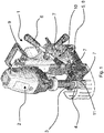
- Figure 1 shows a perspective view of a core drilling machine 1 which includes an electric drive 2 with which a tool holder 3 can be driven in rotation.
- a core drill bit 4 is detachably fastened in the tool holder 3.
- the core drilling machine 1 can be attached to a workpiece to be machined by means of a magnetic base 5.
- the part of the core drilling machine 1, which contains the drive 2 and the tool holder 3, is axially adjusted with respect to an electronic part 10 containing the electronics by means of a rotary wheel 6.
- the core drilling machine 1 contains an information receiver 7 for identifying the core drilling bit 4. This can be attached to the core drilling machine 1 at various points.
- the figure shows the arrangement of the information receiver 7 on a magnet 8 of the magnetic base 5, on a housing 9 of the electronic part 10 and on a support bracket 11. It should be pointed out explicitly that for the identification of the core drill bit 4 it is sufficient to use only one of the information receivers 7 shown.
- the schematically indicated information receivers 7 are designed as RFID antennas, with which information carriers 12 assigned to the core drill bits 4, which are designed as passive RFID transmitters, can be detected.
- a sensor is arranged in the core drilling machine 1, which is used to detect a load variable on the core drilling bit 4 and the operating hours, the cumulative power consumption and the current consumption curve of the core drilling machine 1, the total advance of the core drilling machine 1 and / or the number of holes drilled.
- a wear value of the core drill bit 4 can be determined based on the value of the load size. If the wear value exceeds a wear limit value, an error value is output via an output unit and a signal is generated to inform the user that he must replace the core drill bit 4 promptly.
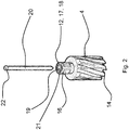
- Figure 2 shows the core drill bit 4 in a perspective view. This has a distal - that is, facing away from the tool holder 3 - first end 13 with a cutting edge 14 and a proximal - that is, the tool holder 3 - second end 15 with a shaft 16 for coupling the core drill bit 4 with a core drill 1.
- the information carrier 12 identifying the core drill bit 4 is assigned to the shaft 16. In the exemplary embodiment shown, this is embodied as an annular passive RFID transmitter which is received in a recess 17 embodied on the proximal end of the shaft 16.
- the recess 17 is designed as an annular groove 18 into which the information carrier 12 is inserted.
- the one shown in the drawing also has a central through opening 19, into which an axially displaceable guide pin 20 is inserted.
- an axially displaceable guide pin 20 is inserted into which an axially displaceable guide pin 20 is inserted.
- the latter rests with its head 22 on an edge 21 formed by the recess 17.
- one of the The information carrier 12 assigned to the core drilling bit 4 and an information receiver 7 assigned to the core drilling machine 1 identifies the core drilling bit 4 received in the tool holder 3 of the core drilling machine 1. If the information receiver 7 is arranged on the magnet 8 of the magnetic base 5, the identification takes place when the user inserts the core drill bit 4 into the tool holder 3 of the core drill 1, since the core drill bit 4 is moved past the information receiver 7 contained in the magnet 8 and is identified in the process. During operation, a load size on the core drill bit 4 is then recorded and a wear value is determined based on the value of the load size.
- This signal is sent from the core drilling machine 1 to a receiver by means of a transmitter.
- the core drill bit 4 is identified on the core drill 1 by means of RFID.
- at least one operating parameter of the core drilling machine 1 is adapted to the core drilling bit 4 used and the optimum feed rate is set for the respective core drilling bit 4 used.
Landscapes
- Engineering & Computer Science (AREA)
- Mechanical Engineering (AREA)
- Drilling Tools (AREA)
- Processing Of Stones Or Stones Resemblance Materials (AREA)
Abstract
Description
- Die Erfindung betrifft ein Verfahren zum Betreiben einer Kernbohrmaschine. Außerdem betrifft die Erfindung eine Kernbohrmaschine und eine Kernbohrkrone zur Durchführung des Verfahrens.
- Zum Bohren von Löchern mit großen Durchmessern in Stahlblechen oder Stahlträgern werden üblicherweise nicht handgeführte Bohrmaschinen mit einem Spiralbohrer, sondern Kernbohrmaschinen mit einer Kernbohrkrone verwendet. Diese Kernbohrmaschinen werden dabei mittels eines Magnetfußes auf dem Werkstück befestigt und dann automatisch oder manuell vorgetrieben. Durch die Kernbohrkrone, die eine hohlzylindrische Form hat, muss dabei nicht das Material des kompletten Lochdurchmessers aufgebohrt werden, sondern es wird letztlich durch die Schneide der Kernbohrkrone nur ein Hohlzylinder ausgeschnitten. Der zylinderförmige Rest fällt dann aus dem Stahlblech heraus oder bleibt in der Kernbohrkrone hängen. Bei Kernbohrmaschinen hat es sich jedoch als problematisch erwiesen, dass die verwendeten Kernbohrkronen durch die auftretende Hitze einem sehr starken Verschleiß unterliegen und damit nur eine begrenzte Standdauer aufweisen. Hierbei ist es für den Nutzer jedoch nur sehr schwer zu erkennen, wann die Schneidleistung der Kernbohrkrone nachlässt und wann er diese also letztlich wechseln bzw. nachschleifen muss. Zudem gibt es eine Vielzahl unterschiedlicher Kernbohrkronen, die sich alle hinsichtlich ihrer Standzeiten voneinander unterscheiden. So wird die Standzeit maßgeblich von dem Durchmesser der Kernbohrkrone sowie von dem verwendeten Material beeinflusst, aus dem die Kernbohrkrone oder deren Schneide gebildet ist. Auch weisen die einzelnen Kernbohrkronen unterschiedliche optimale Betriebsparameter auf. Ein Abweichen hiervon führt zu einem erhöhten Verschleiß und zu längeren Prozesszeiten.
- Der Erfindung liegt daher die Aufgabe zugrunde, ein verbessertes Betriebsverfahren für eine Kernbohrmaschine bereitzustellen. Außerdem ist es Aufgabe der vorliegenden Erfindung, eine verbesserte Kernbohrmaschine und eine verbesserte Bohrkrone bereitzustellen, mit denen das erfindungsgemäße Verfahren durchgeführt werden kann.
- Die das Betriebsverfahren betreffende Aufgabe wird gemäß der Erfindung durch ein Verfahren zum Betreiben einer elektrischen Kernbohrmaschine gelöst, das die folgenden Schritte umfasst:
- Identifizieren einer mit der Kernbohrmaschine lösbar verbundenen Kernbohrkrone mittels eines der Kernbohrkrone zugeordneten Informationsträgers und einem der Kernbohrmaschine zugeordneten Informationsempfänger,
- Erfassen einer Belastungsgröße der Kernbohrkrone,
- Bestimmen eines Verschleißwertes der Kernbohrkrone anhand des Wertes der Belastungsgröße,
- Ausgeben eines Fehlerwertes, wenn der Verschleißwert einen Verschleißgrenzwert überschreitet, und
- Ausgeben eines Signals zur Anzeige der Notwendigkeit, die Kernbohrkrone auszutauschen und/oder zu reparieren.
- Hierdurch wird letztlich ein Betriebsverfahren bereitgestellt, durch das die in der Kernbohrmaschine verwendete Kernbohrkrone automatisch identifiziert wird. Indem dann die Belastungsgröße der Kernbohrkrone erfasst wird, kann ein Verschleißwert anhand des Wertes dieser Belastungsgröße bestimmt werden. Überschreitet dieser Verschleißwert dann den Verschleißgrenzwert, so wird der Fehlerwert ausgegeben, mit welchem dem Nutzer angezeigt werden kann, dass dieser die Kernbohrkrone auswechseln und gegen eine neue Kernbohrkrone austauschen muss. Der Verschleißgrenzwert kann dabei auch explizit deutlich vor dem Lebensdauerende der Kernbohrkrone erreicht werden, um dem Nutzer durch das Signal mitzuteilen, dass er sich zeitnah um Ersatz für die Kernbohrkrone kümmern muss. Auch kann diese Information dazu genutzt werden, dem Nutzer automatisch eine neue oder reparierte Kernbohrkrone zukommen zu lassen, bevor die aktuell verwendete Kernbohrkrone ihre maximale Lebensdauer erreicht, wenn diese Information an den Hersteller übermittelt wird. Dies kann im Rahmen eines Leasings- oder Abo-Models erfolgen. Die Identifizierung der verwendeten Kernbohrkrone erfolgt dabei besonders bevorzugt simultan mit dem Einsetzen der Kernbohrkrone in eine Werkzeugaufnahme, kann aber auch davon vor- bzw. nachgelagert erfolgen. Insbesondere bei hochwertigen Kernbohrkronen ist dabei auch eine Reparatur möglich, indem die Schneide nachgeschliffen wird. Auf dem Informationsträger können dabei neben einer Seriennummer oder einer anderen Information, mit der sich die Kernbohrkrone identifizieren lässt, insbesondere sämtliche Produktionsparameter abgelegt sein. Damit kann dann bei Nachbestellungen oder Reklamationen auf das Produktionslos, das -datum, der Arbeiter, den Herstellungsort zurückgegriffen werden.
- Als günstig hat es sich hierbei auch erwiesen, wenn das Identifizieren der Kernbohrkrone an der Kernbohrmaschine mittels NFC, RFID und/oder Bluetooth erfolgt. Hierdurch wird eine berührungslose Identifizierung der Kernbohrkrone an der Kernbohrmaschine ermöglicht, was sich positiv auf die Benutzerfreundlichkeit des erfindungsgemäßen Betriebsverfahrens auswirkt. Von dem Begriff "RFID" sind dabei sowohl die Varianten UHF (868MHz) und HF (13.56MHz) umfasst. Alternativ ist es im Rahmen der Erfindung auch vorgesehen, dass die Identifizierung durch einen Barcode, der den Informationsträgers bildet und einen korrespondierenden Scanner, der als Informationsempfänger dient, erfolgt.
- Als besonders vorteilhat hat es sich auch erwiesen, wenn ein mindestens ein Betriebsparameter der Kernbohrmaschine an die verwendete Kernbohrkrone angepasst wird. Dies kann insbesondere die Drehzahl der Kernbohrmaschine sein. Hierdurch wird der Arbeitsfortschritt optimiert, da die Kernbohrmaschine stets im optimalen Drehzahlbereich arbeiten kann. Zudem lässt sich hierdurch auch die Lebensdauer der verwendeten Kernbohrkrone steigern. Auch die Kühlmittelzufuhr ist als ein Betriebsparameter aufzufassen.
- Bewährt hat es sich zudem auch, wenn abhängig von der verwendeten Kernbohrkrone der optimale Vorschub angezeigt und/oder eingestellt wird. Hierdurch wird insbesondere berücksichtigt, dass unterschiedliche Kernbohrkronen unterschiedliche optimale Vorschübe aufweisen, sodass es möglich ist, den Vorschub entweder auf den optimalen Wert einzustellen, was bei einem automatischen Vorschub möglich ist, oder dem Nutzer den optimalen Wert bzw. Abweichungen davon anzuzeigen, wodurch das Arbeitsergebnis und die Arbeitsleistung verbessern werden.
- Als günstig hat es sich auch gezeigt, wenn der Verschleißwert durch einen Vergleich zwischen dem erfassten Wert der Belastungsgröße und Kontrolldaten ermittelt wird, die auf einem Speicher hinterlegt sind. Somit kann beispielsweise mittels einer Vergleichsmessung zunächst das Abnutzungsverhalten verschiedener Kernbohrkronen einzeln erfasst und dann in dem Speicher hinterlegt werden. Wird nun die Kernbohrmaschine mit einer dieser Kernbohrkronen verwendet, so kann automatisch aus dem Vergleich zwischen dem Wert der Belastungsgröße und dem Kontrollwert auf den Verschleißwert rückgeschlossen werden.
- Als vorteilhat hat es sich auch gezeigt, wenn die Belastungsgröße ausgewählt ist aus einer Gruppe, die die Betriebsstunden, die kumulierte Leistungsaufnahme, den Verlauf der Stromaufnahme der Kernbohrmaschine, den Gesamtvortrieb der Kernbohrmaschine und/oder die Anzahl der gebohrten Löcher umfasst. Diese Belastungsgrößen lassen sich dabei besonders einfach erfassen.
- Bewährt hat es sich weiterhin, wenn das Signal mittels eines Senders von der Kernbohrmaschine an einen Empfänger versendet wird. Hierbei kann insbesondere der Fehlerwert und/oder der Wert der Belastungsgröße übermittelt werden. Alternativ und/oder ergänzend wird der Fehlerwert und/oder der Wert der Belastungsgröße in einer Speichereinheit der Kernbohrmaschine gespeichert. Auch hat es sich in diesem Zusammenhang bewährt, wenn der Wert der Belastungsgröße und/oder der Fehlerwert vom Nutzer ausgelesen wird. Das Signal kann aber auch akustisch oder optisch sein. Im Rahmen der Erfindung ist es dabei auch vorgesehen, dass der Nutzer den Wert der Belastungsgröße und/oder den Verschleißwert kontinuierlich oder bei Bedarf übermittelt und/oder angezeigt bekommt. Beispielsweise auf einem Smartphone.
- Die die Kernbohrmaschine betreffende Aufgabe wird gemäß der Erfindung gelöst durch eine Kernbohrmaschine, umfassend einen elektrischen Antrieb, mit dem eine Werkzeugaufnahme rotierend antreibbar ist, in der eine Kernbohrkrone lösbar befestigbar ist, einen Informationsempfänger zur Identifizierung der Kernbohrkrone, einen Sensor zur Erfassung einer Belastungsgröße der Kernbohrkrone, eine Auswerteeinheit zur Bestimmung eines Verschleißwertes der Kernbohrkrone anhand des Wertes der Belastungsgröße und eine Ausgabeeinheit zur Ausgabe eines Fehlerwertes beim Überschreiten eines Verschleißgrenzwerts. Hierdurch wird eine Kernbohrmaschine bereitgestellt, die es auf besonders einfache Art und Weise ermöglicht, die verwendete Kernbohrkrone zu identifizieren und deren Verschleiß zu erfassen.
- Bewährt hat es sich dabei besonders auch, wenn der Sensor ausgelegt ist, die Betriebsstunden, die kumulierte Leistungsaufnahme, den Verlauf der Stromaufnahme der Kernbohrmaschine, den Gesamtvortrieb der Kernbohrmaschine und/oder die Anzahl der gebohrten Löcher zu erfassen. Hierdurch wird eine auf die Kernbohrkrone wirkende Belastungsgröße zuverlässig erfasst.
- Als günstig hat es sich auch erwiesen, wenn der Informationsempfänger an einem Magnetfuß der Kernbohrmaschine, an einem Stützbügel der Kernbohrmaschine oder an einem Gehäuse der Kernbohrmaschine angeordnet ist. Besonders bewährt hat es sich in diesem Zusammenhang, wenn der Informationsempfänger dabei so angeordnet ist, dass die Identifizierung der Kernbohrkrone beim Einsetzen in die Werkzeugaufnahme erfolgt, wodurch verhindert wird, dass der Nutzer zwar eine erste Kernbohrkrone mit der Kernbohrmaschine koppelt, dann aber eine zweite Kernbohrkrone in die Werkzeugaufnahme einsetzt und mit dieser arbeitet.
- Die die Kernbohrkrone betreffende Aufgabe wird gemäß der Erfindung gelöst durch eine Kernbohrkrone, umfassend ein distales erstes Ende mit einer Schneide und ein proximales zweites Ende mit einem Schaft zum Koppeln der Kernbohrkrone mit einer Kernbohrmaschine, wobei dem Schaft ein die Kernbohrkrone identifizierender Informationsträger zugeordnet ist. Hierdurch wird eine Kernbohrkrone geschaffen, die in einer entsprechenden Kernbohrmaschine identifiziert werden kann, um den Verschleiß der Kernbohrkrone überwachen zu können.
- Als vorteilhaft hat es sich hierbei auch erwiesen, wenn der Informationsträger als ein ringförmiger passiver Sender ausgebildet ist, der in einer an dem proximalen Ende des Schafts ausgebildeten Aussparung aufgenommen ist. Hierdurch lässt sich der Informationsträger, der beispielweise als ein passiver RFID-Sender gebildet ist, sicher an dem Schaft aufnehmen. Der Informationsträger kann dabei in die Aussparung eingeklebt werden.
- Besonders bewährt hat es sich dabei auch, wenn die Aussparung als eine Ringnut ausgebildet ist. Hierdurch werden Beschädigungen des Informationsträgers vermieden.
- Im Folgenden wird die Erfindung an einem in den Zeichnungen dargestellten Ausführungsbeispiel näher erläutert; es zeigen:
- Fig. 1
- eine perspektivische Ansicht einer erfindungsgemäßen Kernbohrmaschine, und
- Fig. 2
- eine perspektivische Ansicht einer erfindungsgemäßen Kernbohrkrone.
-
Figur 1 zeigt in einer perspektivischen Ansicht eine Kernbohrmaschine 1, die einen elektrischen Antrieb 2 umfasst, mit dem eine Werkzeugaufnahme 3 rotierend antreibbar ist. In der Werkzeugaufnahme 3 ist eine Kernbohrkrone 4 lösbar befestigt. Mittels eines Magnetfußes 5 lässt sich die Kernbohrmaschine 1 auf einem zu bearbeitenden Werkstück befestigen. Durch ein Drehrad 6 wird der Teil der Kernbohrmaschine 1, der den Antrieb 2 und die Werkzeugaufnahme 3 beinhaltet, gegenüber einem die Elektronik enthaltenden Elektronikteil 10 axial verstellen. In der Kernbohrmaschine 1 ist ein Informationsempfänger 7 zur Identifizierung der Kernbohrkrone 4 enthalten. Dieser kann dabei an verschiedenen Stellen an der Kernbohrmaschine 1 befestigt sein. Exemplarisch ist in der Figur die Anordnung des Informationsempfängers 7 an einem Magnet 8 des Magnetfußes 5, an einem Gehäuse 9 des Elektronikteils 10 sowie an einem Stützbügel 11 gezeigt. Explizit sei darauf hingewiesen, dass es für die Identifizierung der Kernbohrkrone 4 ausreichend ist, lediglich einen der gezeigten Informationsempfänger 7 zu verwenden. In dem gezeigten Ausführungsbeispiel sind die schematisch angedeuteten Informationsempfänger 7 als RFID-Antennen ausgebildet, mit denen den Kernbohrkronen 4 zugeordnete Informationsträger 12, die als passive RFID-Sender ausgebildet sind, erfasst werden können. In der Kernbohrmaschine 1 ist ein Sensor angeordnet, der zur Erfassung einer Belastungsgröße der Kernbohrkrone 4 dient und die Betriebsstunden, die kumulierte Leistungsaufnahme, den Verlauf der Stromaufnahme der Kernbohrmaschine 1, den Gesamtvortrieb der Kernbohrmaschine 1 und/oder die Anzahl der gebohrten Löcher erfasst. Mit einer Auswerteeinheit lässt sich ein Verschleißwert der Kernbohrkrone 4 anhand des Wertes der Belastungsgröße bestimmen. Überschreitet der Verschleißwert einen Verschleißgrenzwert, so wird über eine Ausgabeeinheit ein Fehlerwert ausgegeben und ein Signal erzeugt, um dem Nutzer mitzuteilen, dass er die Kernbohrkrone 4 zeitnah austauschen muss. -
Figur 2 zeigt in einer perspektivischen Ansicht die Kernbohrkrone 4. Diese weist ein distales - also von der Werkzeugaufnahme 3 abgewandtes - erstes Ende 13 mit einer Schneide 14 sowie ein proximales - also der Werkzeugaufnahme 3 zugewandtes - zweites Ende 15 mit einem Schaft 16 zum Koppeln der Kernbohrkrone 4 mit einer Kernbohrmaschine 1 auf. Dem Schaft 16 ist dabei der die Kernbohrkrone 4 identifizierende Informationsträger 12 zugeordnet. Dieser ist in dem gezeigten Ausführungsbeispiel als ein ringförmiger passiver RFID-Sender ausgebildet, der in einer an dem proximalen Ende des Schafts 16 ausgebildeten Aussparung 17 aufgenommen ist. Die Aussparung 17 ist hierbei als eine Ringnut 18 ausgebildet, in die der Informationsträger 12 eingesetzt ist. Wie bei Kernbohrkronen 4 üblich, weist auch die in der Zeichnung dargestellte eine zentrale Durchgangsöffnung 19 auf, in die ein axial verschiebbarer Führungsstift 20 eingesetzt wird. Um ein Abschirmen des Informationsträgers 12 durch den Führungsstift 20 zu verhindern, liegt dieser im eingesetzten Zustand mit seinem Kopf 22 auf einem durch die Aussparung 17 gebildeten Rand 21 auf. - Im Folgenden wird noch einmal das erfindungsgemäße Verfahren zum Betreiben einer Kernbohrmaschine 1 anhand der in der
Figur 1 dargestellten Kernbohrmaschine 1 näher erläutert. Zunächst wird mittels eines der Kernbohrkrone 4 zugeordneten Informationsträgers 12 und einem der Kernbohrmaschine 1 zugeordneten Informationsempfänger 7 die in der Werkzeugaufnahme 3 der Kernbohrmaschine 1 aufgenommene Kernbohrkrone 4 identifiziert. Wenn der Informationsempfänger 7 an dem Magneten 8 des Magnetfußes 5 angeordnet ist, so erfolgt die Identifizierung, wenn der Nutzer die Kernbohrkrone 4 in die Werkzeugaufnahme 3 der Kernbohrmaschine 1 einsetzt, da hierbei die Kernbohrkrone 4 an dem in dem Magneten 8 enthaltenen Informationsempfänger 7 vorbeigeführt wird und dabei identifiziert wird. Im Betrieb wird dann eine Belastungsgröße der Kernbohrkrone 4 erfasst und anhand des Wertes der Belastungsgröße ein Verschleißwert bestimmt. Dies erfolgt durch einen Vergleich zwischen dem Wert der erfassten Belastungsgröße und zuvor ermittelten Kontrolldaten, die auf einem Speicher hinterlegt sind. Überschreitet dieser Verschleißwert einen Verschleißgrenzwert, so wird ein Fehlerwert ausgegeben und dann als letzter Schritt dem Nutzer ein Signal ausgegeben, das ihm die Notwendigkeit anzeigt, die Kernbohrkrone 4 auszutauschen bzw. zu reparieren also bspw. nachzuschleifen. Dieses Signal wird dabei mittels eines Senders von der Kernbohrmaschine 1 an einen Empfänger versendet. Bei dem gezeigten Ausführungsbeispiel erfolgt das Identifizieren der Kernbohrkrone 4 an der Kernbohrmaschine 1 mittels RFID. Neben der Verschleißüberwachung wird mindestens ein Betriebsparameter der Kernbohrmaschine 1 an die verwendete Kernbohrkrone 4 angepasst und der für die jeweils verwendete Kernbohrkrone 4 optimale Vorschub eingestellt. -
- 1
- Kernbohrmaschine
- 2
- Antrieb
- 3
- Werkzeugaufnahme
- 4
- Kernbohrkrone
- 5
- Magnetfuß
- 6
- Drehrad
- 7
- Informationsempfänger
- 8
- Magnet
- 9
- Gehäuse
- 10
- Elektronikteil
- 11
- Stützbügel
- 12
- Informationsträger
- 13
- erstes Ende
- 14
- Schneide
- 15
- zweites Ende
- 16
- Schaft
- 17
- Aussparung
- 18
- Ringnut
- 19
- Durchgangsöffnung
- 20
- Führungsstift
- 21
- Rand
- 22
- Kopf
Claims (13)
- Verfahren zum Betreiben einer elektrischen Kernbohrmaschine (1), insbesondere einer Magnetkernbohrmaschine, umfassend die Schritte:- Identifizieren einer mit der Kernbohrmaschine (1) lösbar verbundenen Kernbohrkrone (4) mittels eines der Kernbohrkrone (4) zugeordneten Informationsträgers (12) und einem der Kernbohrmaschine (1) zugeordneten Informationsempfänger (7),- Erfassen einer Belastungsgröße der Kernbohrkrone (4),- Bestimmen eines Verschleißwertes der Kernbohrkrone (4) anhand des Werts der Belastungsgröße, und- Ausgeben eines Fehlerwertes, wenn der Verschleißwert einen Verschleißgrenzwert überschreitet, und- Ausgeben eines Signals zur Anzeige der Notwendigkeit, die Kernbohrkrone (4) auszutauschen und/oder zu reparieren.
- Verfahren nach Anspruch 1, dadurch gekennzeichnet, dass das Identifizieren der Kernbohrkrone (4) an der Kernbohrmaschine (1) mittels NFC, RFID und/oder Bluetooth erfolgt.
- Verfahren nach Anspruch 1 oder 2, dadurch gekennzeichnet, dass mindestens ein Betriebsparameter der Kernbohrmaschine (1) an die verwendete Kernbohrkrone (4) angepasst wird.
- Verfahren nach einem der Ansprüche 1 bis 3, dadurch gekennzeichnet, dass abhängig von der verwendeten Kernbohrkrone (4) der optimale Vorschub angezeigt und/oder eingestellt wird.
- Verfahren nach einem der Ansprüche 1 bis 4, dadurch gekennzeichnet, dass der Verschleißwert durch einen Vergleich zwischen dem Wert der erfassten Belastungsgröße und Kontrolldaten ermittelt wird, die auf einem Speicher hinterlegt sind.
- Verfahren nach einem der Ansprüche 1 bis 5, dadurch gekennzeichnet, dass die Belastungsgröße ausgewählt ist aus einer Gruppe, die die Betriebsstunden, die kumulierte Leistungsaufnahme, den Verlauf der Stromaufnahme der Kernbohrmaschine (1), den Gesamtvortrieb der Kernbohrmaschine (1) und/oder die Anzahl der gebohrten Löcher umfasst.
- Verfahren nach einem der Ansprüche 1 bis 6, dadurch gekennzeichnet, dass das Signal mittels eines Senders von der Kernbohrmaschine (1) an einen Empfänger versendet wird.
- Kernbohrmaschine (1) zur Durchführung des Verfahrens nach einem der Ansprüche 1 bis 7, umfassend einen elektrischen Antrieb (2), mit dem eine Werkzeugaufnahme (3) rotierend antreibbar ist, in die eine Kernbohrkrone (4) lösbar befestigbar ist, einen Informationsempfänger (7) zur Identifizierung der Kernbohrkrone (4), einen Sensor zur Erfassung von einer Belastungsgröße der Kernbohrkrone (4), eine Auswerteeinheit zur Bestimmung eines Verschleißwertes der Kernbohrkrone (4) anhand des Wertes der Belastungsgröße und eine Ausgabeeinheit zur Ausgabe eines Fehlerwertes beim Überschreiten eines Verschleißgrenzwerts.
- Kernbohrmaschine (1) nach Anspruch 8, dadurch gekennzeichnet, dass der Sensor ausgelegt ist, die Betriebsstunden, die kumulierte Leistungsaufnahme, den Verlauf der Stromaufnahme der Kernbohrmaschine (1), den Gesamtvortrieb der Kernbohrmaschine (1) und/oder die Anzahl der gebohrten Löcher zu erfassen.
- Kernbohrmaschine (1) nach Anspruch 8 oder 9, dadurch gekennzeichnet, dass der Informationsempfänger (7) an einem Magneten (8) der Kernbohrmaschine (1), an einem Stützbügel (11) der Kernbohrmaschine (1) oder an einem Gehäuse (9) der Kernbohrmaschine (1) angeordnet ist.
- Kernbohrkrone (4) zur Durchführung des Verfahrens nach einem der Ansprüche 1 bis 7, umfassend ein distales erstes Ende (13) mit einer Schneide (14) und ein proximales zweites Ende (15) mit einem Schaft (16) zum Koppeln der Kernbohrkrone (4) mit einer Kernbohrmaschine (1), wobei dem Schaft (16) ein die Kernbohrkrone (4) identifizierender Informationsträger (12) zugeordnet ist.
- Kernbohrkrone (4) nach Anspruch 11, dadurch gekennzeichnet, dass der Informationsträger (12) als ein ringförmiger passiver Sender ausgebildet ist, der in einer an dem proximalen Ende des Schafts (16) ausgebildeten Aussparung (17) aufgenommen ist.
- Kernbohrkrone (4) nach Anspruch 11 oder 12, dadurch gekennzeichnet, dass die Aussparung (17) als eine Ringnut (18) ausgebildet ist.
Applications Claiming Priority (1)
| Application Number | Priority Date | Filing Date | Title |
|---|---|---|---|
| DE102019112999.0A DE102019112999A1 (de) | 2019-05-16 | 2019-05-16 | Verfahren zum Betreiben einer Kernbohrmaschine sowie Kernbohrmaschine und Kernbohrkrone zur Durchführung des Verfahrens |
Publications (2)
| Publication Number | Publication Date |
|---|---|
| EP3738703A1 true EP3738703A1 (de) | 2020-11-18 |
| EP3738703B1 EP3738703B1 (de) | 2023-08-16 |
Family
ID=70292831
Family Applications (1)
| Application Number | Title | Priority Date | Filing Date |
|---|---|---|---|
| EP20169791.9A Active EP3738703B1 (de) | 2019-05-16 | 2020-04-16 | Verfahren zum betreiben einer kernbohrmaschine sowie kernbohrmaschine und kernbohrkrone zur durchführung des verfahrens |
Country Status (4)
| Country | Link |
|---|---|
| US (1) | US11148211B2 (de) |
| EP (1) | EP3738703B1 (de) |
| CN (1) | CN111940791B (de) |
| DE (1) | DE102019112999A1 (de) |
Families Citing this family (6)
| Publication number | Priority date | Publication date | Assignee | Title |
|---|---|---|---|---|
| SE543975C2 (en) * | 2020-04-06 | 2021-10-12 | Husqvarna Ab | RFID arrangements for rotatable work tools |
| DE102020216459A1 (de) * | 2020-12-22 | 2022-06-23 | Robert Bosch Gesellschaft mit beschränkter Haftung | Elektronikmodul, Einsatzwerkzeugsystem mit einem derartigen Elektronikmodul und Verfahren zu einem Betrieb eines derartigen Elektronikmoduls |
| EP4101602A1 (de) * | 2021-06-11 | 2022-12-14 | Hilti Aktiengesellschaft | Verfahren zur analyse eines werkzeugs und mobile werkzeugmaschine |
| US12703073B2 (en) | 2023-01-25 | 2026-08-11 | Milwaukee Electric Tool Corporation | Systems and methods for identification of power tool accessories |
| IT202400002410A1 (it) * | 2024-02-06 | 2025-08-06 | Bizcode S R L | Un metodo di identificazione e tracciamento |
| CN119216633B (zh) * | 2024-12-04 | 2025-03-28 | 山建大工程技术(山东)有限公司 | 一种消防施工用管道切割开孔设备 |
Citations (3)
| Publication number | Priority date | Publication date | Assignee | Title |
|---|---|---|---|---|
| US7431682B2 (en) * | 2004-12-17 | 2008-10-07 | Milwaukee Electric Tool Corporation | Smart accessories for power tools |
| US20090175694A1 (en) * | 2007-12-11 | 2009-07-09 | Karen Anne Craig | Cutting tool with integrated circuit chip |
| EP3299100A1 (de) * | 2016-09-23 | 2018-03-28 | HILTI Aktiengesellschaft | Kernbohrmeissel |
Family Cites Families (15)
| Publication number | Priority date | Publication date | Assignee | Title |
|---|---|---|---|---|
| FR2368336A1 (fr) * | 1976-10-20 | 1978-05-19 | Irigny Mecanique | Porte-outil pour machines automatiques d'usinage |
| DE2906892A1 (de) * | 1979-02-22 | 1980-09-11 | Kurt Manfred Dipl Phys Tischer | Anordnung fuer eine werkzeugueberwachung und -bruchkontrolle mit hilfe von piezoxiden |
| CA1243744A (en) * | 1984-06-18 | 1988-10-25 | Borg-Warner Corporation | Cutting tool wear monitor |
| DE4238338A1 (de) * | 1992-11-13 | 1994-05-19 | Heller Geb Gmbh Maschf | Überwachungseinrichtung für Werkzeuge einer Bearbeitungsmaschine |
| US5940787A (en) * | 1993-12-10 | 1999-08-17 | U.S. Tech Corporation | Apparatuses and methods of monitoring the condition of tools and workpieces |
| JP3644129B2 (ja) * | 1996-05-20 | 2005-04-27 | ブラザー工業株式会社 | 切削加工装置およびその異常検出方法 |
| DE10304405B4 (de) * | 2003-02-01 | 2012-10-04 | Hilti Aktiengesellschaft | Verfahren zur Regelung einer Kernbohrmaschine |
| DE102004033361A1 (de) * | 2004-07-02 | 2006-01-19 | C. & E. Fein Gmbh | Bohrmaschine, insbesondere Kernlochbohrmaschine |
| FR2904446B1 (fr) * | 2006-07-28 | 2008-10-03 | Snecma Sa | Procede de detection et de quantification d'anomalies de percage |
| DE102009040513A1 (de) * | 2009-09-02 | 2011-03-03 | C. & E. Fein Gmbh | Kernbohrmaschine mit austauschbarer Bohrkrone |
| CN102847976A (zh) * | 2012-08-28 | 2013-01-02 | 方荣泉 | 快速钻孔自动断削磁力空芯钻 |
| EP3180160B1 (de) * | 2014-08-15 | 2025-11-05 | Baron Investments LLC | Datenerfassung, übertragung und rückmeldung in arbeitswerkzeugen |
| EP3088151A1 (de) * | 2015-04-28 | 2016-11-02 | HILTI Aktiengesellschaft | Rückfahrmodus für kernbohrsysteme |
| US20180178293A1 (en) * | 2015-06-27 | 2018-06-28 | Yamamoto Metal Technos Co., Ltd. | Rotary machine tool equipped with sensor for real-time detection of state |
| FR3046809B1 (fr) * | 2016-01-20 | 2019-06-28 | Seti-Tec | Procede de determination de l'etat d'usage d'un foret, et dispositif correspondant |
-
2019
- 2019-05-16 DE DE102019112999.0A patent/DE102019112999A1/de not_active Withdrawn
-
2020
- 2020-04-16 EP EP20169791.9A patent/EP3738703B1/de active Active
- 2020-05-15 CN CN202010412707.9A patent/CN111940791B/zh not_active Expired - Fee Related
- 2020-05-18 US US16/876,645 patent/US11148211B2/en not_active Expired - Fee Related
Patent Citations (3)
| Publication number | Priority date | Publication date | Assignee | Title |
|---|---|---|---|---|
| US7431682B2 (en) * | 2004-12-17 | 2008-10-07 | Milwaukee Electric Tool Corporation | Smart accessories for power tools |
| US20090175694A1 (en) * | 2007-12-11 | 2009-07-09 | Karen Anne Craig | Cutting tool with integrated circuit chip |
| EP3299100A1 (de) * | 2016-09-23 | 2018-03-28 | HILTI Aktiengesellschaft | Kernbohrmeissel |
Also Published As
| Publication number | Publication date |
|---|---|
| CN111940791B (zh) | 2023-02-28 |
| EP3738703B1 (de) | 2023-08-16 |
| US20200361008A1 (en) | 2020-11-19 |
| CN111940791A (zh) | 2020-11-17 |
| DE102019112999A1 (de) | 2020-11-19 |
| US11148211B2 (en) | 2021-10-19 |
Similar Documents
| Publication | Publication Date | Title |
|---|---|---|
| EP3738703B1 (de) | Verfahren zum betreiben einer kernbohrmaschine sowie kernbohrmaschine und kernbohrkrone zur durchführung des verfahrens | |
| DE102010056524B4 (de) | Tragbares Werkzeug und Verfahren zum Durchführen von Arbeitsvorgängen mit diesem Werkzeug | |
| EP0300317B2 (de) | Einrichtung für in zahnärztliche Behandlungsinstrumente einsetzbare Werkzeuge | |
| EP3027359B1 (de) | Anordnung mit einer handgeführten werkzeugmaschine und einer schruppscheibe | |
| DE60130971T2 (de) | Intelligentes werkzeugmaschinensystem | |
| DE19916710B4 (de) | Werkzeugantriebseinrichtung, insbesondere für Werkzeugmaschinen | |
| EP3482859B1 (de) | System für einen optimierten betrieb einer werkzeugmaschine | |
| EP1255627A1 (de) | Spindel mit einem datenspeicherelement | |
| EP2065988A2 (de) | Verfahren und Vorrichtung zur Reparatur eines Schleifringes im eingebauten Zustand | |
| DE102007063200A1 (de) | Verfahren und Vorrichtung zur Feinbearbeitung eines Werkstücks mit einem vielschneidigen Rotationswerkzeug sowie Verwendung eines Körperschallsensors | |
| DE102016217251A1 (de) | Verfahren zum Bearbeiten eines Werkstücks aus Hartmetall für die Herstellung eines Werkzeuggrundkörpers an einer numerisch gesteuerten Werkzeugmaschine mit werkzeugtragender Arbeitsspindel | |
| DE202017105356U1 (de) | Aufbau eines intelligenten Induktionswerkzeugs | |
| EP2025445B1 (de) | Spindel mit einem per Funk auslesbaren Datenerfassungselement | |
| DE102006008395A1 (de) | Rotierendes Werkzeug mit elektronischem Datenträger | |
| EP3339996A1 (de) | Gerätesystem mit einem werkzeug- oder messgerät | |
| EP2545876A2 (de) | Antriebseinheit | |
| DE102006052602B4 (de) | Verfahren und Vorrichtung zur Kühlmittelversorgung spanender Werkzeuge | |
| EP3455683A1 (de) | System und verfahren zur verarbeitung von werkzeugbezogenen daten | |
| EP2347846A1 (de) | Zirkularsäge | |
| DE102018001527B4 (de) | Numerische Steuervorrichtung einer Werkzeugmaschine | |
| DE212018000196U1 (de) | Bearbeitungsspindel | |
| EP4316736A1 (de) | Verfahren zum steuern und regeln einer werkzeugmaschine und erfassungsvorringung sowie system zur durchführung des verfahrens | |
| EP4011547A1 (de) | Verfahren zur überwachung einer temperatur in einem arbeitsbereich einer werkzeugmaschine und werkzeugmaschine | |
| DE10046529A1 (de) | Bohrsystem mit elektronischer Durchmesserüberwachung | |
| DE10127972C1 (de) | Vorrichtung und ein Verfahren zum spanabhebenden Bearbeiten von Werkstücken |
Legal Events
| Date | Code | Title | Description |
|---|---|---|---|
| PUAI | Public reference made under article 153(3) epc to a published international application that has entered the european phase |
Free format text: ORIGINAL CODE: 0009012 |
|
| STAA | Information on the status of an ep patent application or granted ep patent |
Free format text: STATUS: THE APPLICATION HAS BEEN PUBLISHED |
|
| AK | Designated contracting states |
Kind code of ref document: A1 Designated state(s): AL AT BE BG CH CY CZ DE DK EE ES FI FR GB GR HR HU IE IS IT LI LT LU LV MC MK MT NL NO PL PT RO RS SE SI SK SM TR |
|
| AX | Request for extension of the european patent |
Extension state: BA ME |
|
| STAA | Information on the status of an ep patent application or granted ep patent |
Free format text: STATUS: REQUEST FOR EXAMINATION WAS MADE |
|
| 17P | Request for examination filed |
Effective date: 20201207 |
|
| RBV | Designated contracting states (corrected) |
Designated state(s): AL AT BE BG CH CY CZ DE DK EE ES FI FR GB GR HR HU IE IS IT LI LT LU LV MC MK MT NL NO PL PT RO RS SE SI SK SM TR |
|
| RIC1 | Information provided on ipc code assigned before grant |
Ipc: B23Q 17/09 20060101ALI20230428BHEP Ipc: B25H 1/00 20060101ALI20230428BHEP Ipc: B25F 5/00 20060101ALI20230428BHEP Ipc: B23B 51/04 20060101AFI20230428BHEP |
|
| GRAP | Despatch of communication of intention to grant a patent |
Free format text: ORIGINAL CODE: EPIDOSNIGR1 |
|
| STAA | Information on the status of an ep patent application or granted ep patent |
Free format text: STATUS: GRANT OF PATENT IS INTENDED |
|
| GRAS | Grant fee paid |
Free format text: ORIGINAL CODE: EPIDOSNIGR3 |
|
| INTG | Intention to grant announced |
Effective date: 20230613 |
|
| GRAA | (expected) grant |
Free format text: ORIGINAL CODE: 0009210 |
|
| STAA | Information on the status of an ep patent application or granted ep patent |
Free format text: STATUS: THE PATENT HAS BEEN GRANTED |
|
| P01 | Opt-out of the competence of the unified patent court (upc) registered |
Effective date: 20230703 |
|
| AK | Designated contracting states |
Kind code of ref document: B1 Designated state(s): AL AT BE BG CH CY CZ DE DK EE ES FI FR GB GR HR HU IE IS IT LI LT LU LV MC MK MT NL NO PL PT RO RS SE SI SK SM TR |
|
| REG | Reference to a national code |
Ref country code: CH Ref legal event code: EP Ref country code: DE Ref legal event code: R096 Ref document number: 502020004702 Country of ref document: DE |
|
| REG | Reference to a national code |
Ref country code: IE Ref legal event code: FG4D Free format text: LANGUAGE OF EP DOCUMENT: GERMAN |
|
| REG | Reference to a national code |
Ref country code: LT Ref legal event code: MG9D |
|
| REG | Reference to a national code |
Ref country code: NL Ref legal event code: MP Effective date: 20230816 |
|
| PG25 | Lapsed in a contracting state [announced via postgrant information from national office to epo] |
Ref country code: GR Free format text: LAPSE BECAUSE OF FAILURE TO SUBMIT A TRANSLATION OF THE DESCRIPTION OR TO PAY THE FEE WITHIN THE PRESCRIBED TIME-LIMIT Effective date: 20231117 |
|
| PG25 | Lapsed in a contracting state [announced via postgrant information from national office to epo] |
Ref country code: IS Free format text: LAPSE BECAUSE OF FAILURE TO SUBMIT A TRANSLATION OF THE DESCRIPTION OR TO PAY THE FEE WITHIN THE PRESCRIBED TIME-LIMIT Effective date: 20231216 |
|
| PG25 | Lapsed in a contracting state [announced via postgrant information from national office to epo] |
Ref country code: SE Free format text: LAPSE BECAUSE OF FAILURE TO SUBMIT A TRANSLATION OF THE DESCRIPTION OR TO PAY THE FEE WITHIN THE PRESCRIBED TIME-LIMIT Effective date: 20230816 Ref country code: RS Free format text: LAPSE BECAUSE OF FAILURE TO SUBMIT A TRANSLATION OF THE DESCRIPTION OR TO PAY THE FEE WITHIN THE PRESCRIBED TIME-LIMIT Effective date: 20230816 Ref country code: PT Free format text: LAPSE BECAUSE OF FAILURE TO SUBMIT A TRANSLATION OF THE DESCRIPTION OR TO PAY THE FEE WITHIN THE PRESCRIBED TIME-LIMIT Effective date: 20231218 Ref country code: NO Free format text: LAPSE BECAUSE OF FAILURE TO SUBMIT A TRANSLATION OF THE DESCRIPTION OR TO PAY THE FEE WITHIN THE PRESCRIBED TIME-LIMIT Effective date: 20231116 Ref country code: NL Free format text: LAPSE BECAUSE OF FAILURE TO SUBMIT A TRANSLATION OF THE DESCRIPTION OR TO PAY THE FEE WITHIN THE PRESCRIBED TIME-LIMIT Effective date: 20230816 Ref country code: LV Free format text: LAPSE BECAUSE OF FAILURE TO SUBMIT A TRANSLATION OF THE DESCRIPTION OR TO PAY THE FEE WITHIN THE PRESCRIBED TIME-LIMIT Effective date: 20230816 Ref country code: LT Free format text: LAPSE BECAUSE OF FAILURE TO SUBMIT A TRANSLATION OF THE DESCRIPTION OR TO PAY THE FEE WITHIN THE PRESCRIBED TIME-LIMIT Effective date: 20230816 Ref country code: IS Free format text: LAPSE BECAUSE OF FAILURE TO SUBMIT A TRANSLATION OF THE DESCRIPTION OR TO PAY THE FEE WITHIN THE PRESCRIBED TIME-LIMIT Effective date: 20231216 Ref country code: HR Free format text: LAPSE BECAUSE OF FAILURE TO SUBMIT A TRANSLATION OF THE DESCRIPTION OR TO PAY THE FEE WITHIN THE PRESCRIBED TIME-LIMIT Effective date: 20230816 Ref country code: GR Free format text: LAPSE BECAUSE OF FAILURE TO SUBMIT A TRANSLATION OF THE DESCRIPTION OR TO PAY THE FEE WITHIN THE PRESCRIBED TIME-LIMIT Effective date: 20231117 Ref country code: FI Free format text: LAPSE BECAUSE OF FAILURE TO SUBMIT A TRANSLATION OF THE DESCRIPTION OR TO PAY THE FEE WITHIN THE PRESCRIBED TIME-LIMIT Effective date: 20230816 |
|
| PG25 | Lapsed in a contracting state [announced via postgrant information from national office to epo] |
Ref country code: PL Free format text: LAPSE BECAUSE OF FAILURE TO SUBMIT A TRANSLATION OF THE DESCRIPTION OR TO PAY THE FEE WITHIN THE PRESCRIBED TIME-LIMIT Effective date: 20230816 |
|
| PG25 | Lapsed in a contracting state [announced via postgrant information from national office to epo] |
Ref country code: ES Free format text: LAPSE BECAUSE OF FAILURE TO SUBMIT A TRANSLATION OF THE DESCRIPTION OR TO PAY THE FEE WITHIN THE PRESCRIBED TIME-LIMIT Effective date: 20230816 |
|
| PG25 | Lapsed in a contracting state [announced via postgrant information from national office to epo] |
Ref country code: SM Free format text: LAPSE BECAUSE OF FAILURE TO SUBMIT A TRANSLATION OF THE DESCRIPTION OR TO PAY THE FEE WITHIN THE PRESCRIBED TIME-LIMIT Effective date: 20230816 Ref country code: RO Free format text: LAPSE BECAUSE OF FAILURE TO SUBMIT A TRANSLATION OF THE DESCRIPTION OR TO PAY THE FEE WITHIN THE PRESCRIBED TIME-LIMIT Effective date: 20230816 Ref country code: ES Free format text: LAPSE BECAUSE OF FAILURE TO SUBMIT A TRANSLATION OF THE DESCRIPTION OR TO PAY THE FEE WITHIN THE PRESCRIBED TIME-LIMIT Effective date: 20230816 Ref country code: EE Free format text: LAPSE BECAUSE OF FAILURE TO SUBMIT A TRANSLATION OF THE DESCRIPTION OR TO PAY THE FEE WITHIN THE PRESCRIBED TIME-LIMIT Effective date: 20230816 Ref country code: DK Free format text: LAPSE BECAUSE OF FAILURE TO SUBMIT A TRANSLATION OF THE DESCRIPTION OR TO PAY THE FEE WITHIN THE PRESCRIBED TIME-LIMIT Effective date: 20230816 Ref country code: CZ Free format text: LAPSE BECAUSE OF FAILURE TO SUBMIT A TRANSLATION OF THE DESCRIPTION OR TO PAY THE FEE WITHIN THE PRESCRIBED TIME-LIMIT Effective date: 20230816 Ref country code: SK Free format text: LAPSE BECAUSE OF FAILURE TO SUBMIT A TRANSLATION OF THE DESCRIPTION OR TO PAY THE FEE WITHIN THE PRESCRIBED TIME-LIMIT Effective date: 20230816 |
|
| REG | Reference to a national code |
Ref country code: DE Ref legal event code: R097 Ref document number: 502020004702 Country of ref document: DE |
|
| PLBE | No opposition filed within time limit |
Free format text: ORIGINAL CODE: 0009261 |
|
| STAA | Information on the status of an ep patent application or granted ep patent |
Free format text: STATUS: NO OPPOSITION FILED WITHIN TIME LIMIT |
|
| PGFP | Annual fee paid to national office [announced via postgrant information from national office to epo] |
Ref country code: CH Payment date: 20240501 Year of fee payment: 5 |
|
| 26N | No opposition filed |
Effective date: 20240517 |
|
| PG25 | Lapsed in a contracting state [announced via postgrant information from national office to epo] |
Ref country code: SI Free format text: LAPSE BECAUSE OF FAILURE TO SUBMIT A TRANSLATION OF THE DESCRIPTION OR TO PAY THE FEE WITHIN THE PRESCRIBED TIME-LIMIT Effective date: 20230816 |
|
| PGFP | Annual fee paid to national office [announced via postgrant information from national office to epo] |
Ref country code: FR Payment date: 20240417 Year of fee payment: 5 |
|
| PGFP | Annual fee paid to national office [announced via postgrant information from national office to epo] |
Ref country code: IT Payment date: 20240430 Year of fee payment: 5 |
|
| PG25 | Lapsed in a contracting state [announced via postgrant information from national office to epo] |
Ref country code: BG Free format text: LAPSE BECAUSE OF FAILURE TO SUBMIT A TRANSLATION OF THE DESCRIPTION OR TO PAY THE FEE WITHIN THE PRESCRIBED TIME-LIMIT Effective date: 20230816 |
|
| PG25 | Lapsed in a contracting state [announced via postgrant information from national office to epo] |
Ref country code: MC Free format text: LAPSE BECAUSE OF FAILURE TO SUBMIT A TRANSLATION OF THE DESCRIPTION OR TO PAY THE FEE WITHIN THE PRESCRIBED TIME-LIMIT Effective date: 20230816 |
|
| PG25 | Lapsed in a contracting state [announced via postgrant information from national office to epo] |
Ref country code: MC Free format text: LAPSE BECAUSE OF FAILURE TO SUBMIT A TRANSLATION OF THE DESCRIPTION OR TO PAY THE FEE WITHIN THE PRESCRIBED TIME-LIMIT Effective date: 20230816 Ref country code: BG Free format text: LAPSE BECAUSE OF FAILURE TO SUBMIT A TRANSLATION OF THE DESCRIPTION OR TO PAY THE FEE WITHIN THE PRESCRIBED TIME-LIMIT Effective date: 20230816 |
|
| PG25 | Lapsed in a contracting state [announced via postgrant information from national office to epo] |
Ref country code: LU Free format text: LAPSE BECAUSE OF NON-PAYMENT OF DUE FEES Effective date: 20240416 |
|
| GBPC | Gb: european patent ceased through non-payment of renewal fee |
Effective date: 20240416 |
|
| REG | Reference to a national code |
Ref country code: BE Ref legal event code: MM Effective date: 20240430 |
|
| PG25 | Lapsed in a contracting state [announced via postgrant information from national office to epo] |
Ref country code: LU Free format text: LAPSE BECAUSE OF NON-PAYMENT OF DUE FEES Effective date: 20240416 |
|
| PG25 | Lapsed in a contracting state [announced via postgrant information from national office to epo] |
Ref country code: BE Free format text: LAPSE BECAUSE OF NON-PAYMENT OF DUE FEES Effective date: 20240430 |
|
| PG25 | Lapsed in a contracting state [announced via postgrant information from national office to epo] |
Ref country code: GB Free format text: LAPSE BECAUSE OF NON-PAYMENT OF DUE FEES Effective date: 20240416 |
|
| PG25 | Lapsed in a contracting state [announced via postgrant information from national office to epo] |
Ref country code: GB Free format text: LAPSE BECAUSE OF NON-PAYMENT OF DUE FEES Effective date: 20240416 Ref country code: BE Free format text: LAPSE BECAUSE OF NON-PAYMENT OF DUE FEES Effective date: 20240430 |
|
| PG25 | Lapsed in a contracting state [announced via postgrant information from national office to epo] |
Ref country code: IE Free format text: LAPSE BECAUSE OF NON-PAYMENT OF DUE FEES Effective date: 20240416 |
|
| PGFP | Annual fee paid to national office [announced via postgrant information from national office to epo] |
Ref country code: AT Payment date: 20250721 Year of fee payment: 5 |
|
| PG25 | Lapsed in a contracting state [announced via postgrant information from national office to epo] |
Ref country code: CY Free format text: LAPSE BECAUSE OF FAILURE TO SUBMIT A TRANSLATION OF THE DESCRIPTION OR TO PAY THE FEE WITHIN THE PRESCRIBED TIME-LIMIT; INVALID AB INITIO Effective date: 20200416 |
|
| PG25 | Lapsed in a contracting state [announced via postgrant information from national office to epo] |
Ref country code: HU Free format text: LAPSE BECAUSE OF FAILURE TO SUBMIT A TRANSLATION OF THE DESCRIPTION OR TO PAY THE FEE WITHIN THE PRESCRIBED TIME-LIMIT; INVALID AB INITIO Effective date: 20200416 |
|
| REG | Reference to a national code |
Ref country code: CH Ref legal event code: H13 Free format text: ST27 STATUS EVENT CODE: U-0-0-H10-H13 (AS PROVIDED BY THE NATIONAL OFFICE) Effective date: 20251125 |
|
| PG25 | Lapsed in a contracting state [announced via postgrant information from national office to epo] |
Ref country code: FR Free format text: LAPSE BECAUSE OF NON-PAYMENT OF DUE FEES Effective date: 20250430 |
|
| PG25 | Lapsed in a contracting state [announced via postgrant information from national office to epo] |
Ref country code: CH Free format text: LAPSE BECAUSE OF NON-PAYMENT OF DUE FEES Effective date: 20250430 |
|
| PG25 | Lapsed in a contracting state [announced via postgrant information from national office to epo] |
Ref country code: IT Free format text: LAPSE BECAUSE OF NON-PAYMENT OF DUE FEES Effective date: 20250416 |
|
| PG25 | Lapsed in a contracting state [announced via postgrant information from national office to epo] |
Ref country code: TR Free format text: LAPSE BECAUSE OF FAILURE TO SUBMIT A TRANSLATION OF THE DESCRIPTION OR TO PAY THE FEE WITHIN THE PRESCRIBED TIME-LIMIT Effective date: 20230816 |
|
| REG | Reference to a national code |
Ref country code: AT Ref legal event code: MM01 Ref document number: 1599548 Country of ref document: AT Kind code of ref document: T Effective date: 20250416 |
|
| PGFP | Annual fee paid to national office [announced via postgrant information from national office to epo] |
Ref country code: DE Payment date: 20260420 Year of fee payment: 7 |
|
| PG25 | Lapsed in a contracting state [announced via postgrant information from national office to epo] |
Ref country code: AT Free format text: LAPSE BECAUSE OF NON-PAYMENT OF DUE FEES Effective date: 20250416 |