EP3088151A1 - Rückfahrmodus für kernbohrsysteme - Google Patents
Rückfahrmodus für kernbohrsysteme Download PDFInfo
- Publication number
- EP3088151A1 EP3088151A1 EP15165313.6A EP15165313A EP3088151A1 EP 3088151 A1 EP3088151 A1 EP 3088151A1 EP 15165313 A EP15165313 A EP 15165313A EP 3088151 A1 EP3088151 A1 EP 3088151A1
- Authority
- EP
- European Patent Office
- Prior art keywords
- core drilling
- machine
- drilling
- rotational speed
- feed device
- Prior art date
- Legal status (The legal status is an assumption and is not a legal conclusion. Google has not performed a legal analysis and makes no representation as to the accuracy of the status listed.)
- Withdrawn
Links
Images


Classifications
-
- B—PERFORMING OPERATIONS; TRANSPORTING
- B23—MACHINE TOOLS; METAL-WORKING NOT OTHERWISE PROVIDED FOR
- B23B—TURNING; BORING
- B23B35/00—Methods for boring or drilling, or for working essentially requiring the use of boring or drilling machines; Use of auxiliary equipment in connection with such methods
-
- B—PERFORMING OPERATIONS; TRANSPORTING
- B23—MACHINE TOOLS; METAL-WORKING NOT OTHERWISE PROVIDED FOR
- B23B—TURNING; BORING
- B23B49/00—Measuring or gauging equipment on boring machines for positioning or guiding the drill; Devices for indicating failure of drills during boring; Centering devices for holes to be bored
-
- B—PERFORMING OPERATIONS; TRANSPORTING
- B23—MACHINE TOOLS; METAL-WORKING NOT OTHERWISE PROVIDED FOR
- B23B—TURNING; BORING
- B23B51/00—Tools for drilling machines
- B23B51/04—Drills for trepanning
-
- B—PERFORMING OPERATIONS; TRANSPORTING
- B23—MACHINE TOOLS; METAL-WORKING NOT OTHERWISE PROVIDED FOR
- B23Q—DETAILS, COMPONENTS, OR ACCESSORIES FOR MACHINE TOOLS, e.g. ARRANGEMENTS FOR COPYING OR CONTROLLING; MACHINE TOOLS IN GENERAL CHARACTERISED BY THE CONSTRUCTION OF PARTICULAR DETAILS OR COMPONENTS; COMBINATIONS OR ASSOCIATIONS OF METAL-WORKING MACHINES, NOT DIRECTED TO A PARTICULAR RESULT
- B23Q5/00—Driving or feeding mechanisms; Control arrangements therefor
- B23Q5/02—Driving main working members
- B23Q5/04—Driving main working members rotary shafts, e.g. working-spindles
- B23Q5/20—Adjusting or stopping working-spindles in a predetermined position
-
- B—PERFORMING OPERATIONS; TRANSPORTING
- B28—WORKING CEMENT, CLAY, OR STONE
- B28D—WORKING STONE OR STONE-LIKE MATERIALS
- B28D1/00—Working stone or stone-like materials, e.g. brick, concrete or glass, not provided for elsewhere; Machines, devices, tools therefor
- B28D1/02—Working stone or stone-like materials, e.g. brick, concrete or glass, not provided for elsewhere; Machines, devices, tools therefor by sawing
- B28D1/04—Working stone or stone-like materials, e.g. brick, concrete or glass, not provided for elsewhere; Machines, devices, tools therefor by sawing with circular or cylindrical saw-blades or saw-discs
- B28D1/041—Working stone or stone-like materials, e.g. brick, concrete or glass, not provided for elsewhere; Machines, devices, tools therefor by sawing with circular or cylindrical saw-blades or saw-discs with cylinder saws, e.g. trepanning; saw cylinders, e.g. having their cutting rim equipped with abrasive particles
-
- B—PERFORMING OPERATIONS; TRANSPORTING
- B28—WORKING CEMENT, CLAY, OR STONE
- B28D—WORKING STONE OR STONE-LIKE MATERIALS
- B28D1/00—Working stone or stone-like materials, e.g. brick, concrete or glass, not provided for elsewhere; Machines, devices, tools therefor
- B28D1/14—Working stone or stone-like materials, e.g. brick, concrete or glass, not provided for elsewhere; Machines, devices, tools therefor by boring or drilling
-
- B—PERFORMING OPERATIONS; TRANSPORTING
- B28—WORKING CEMENT, CLAY, OR STONE
- B28D—WORKING STONE OR STONE-LIKE MATERIALS
- B28D7/00—Accessories specially adapted for use with machines or devices of the preceding groups
-
- B—PERFORMING OPERATIONS; TRANSPORTING
- B28—WORKING CEMENT, CLAY, OR STONE
- B28D—WORKING STONE OR STONE-LIKE MATERIALS
- B28D7/00—Accessories specially adapted for use with machines or devices of the preceding groups
- B28D7/005—Devices for the automatic drive or the program control of the machines
-
- E—FIXED CONSTRUCTIONS
- E21—EARTH DRILLING; MINING
- E21B—EARTH DRILLING, e.g. DEEP DRILLING; OBTAINING OIL, GAS, WATER, SOLUBLE OR MELTABLE MATERIALS OR A SLURRY OF MINERALS FROM WELLS
- E21B44/00—Automatic control systems specially adapted for drilling operations, i.e. self-operating systems which function to carry out or modify a drilling operation without intervention of a human operator, e.g. computer-controlled drilling systems; Systems specially adapted for monitoring a plurality of drilling variables or conditions
-
- B—PERFORMING OPERATIONS; TRANSPORTING
- B23—MACHINE TOOLS; METAL-WORKING NOT OTHERWISE PROVIDED FOR
- B23B—TURNING; BORING
- B23B2226/00—Materials of tools or workpieces not comprising a metal
- B23B2226/75—Stone, rock or concrete
-
- B—PERFORMING OPERATIONS; TRANSPORTING
- B23—MACHINE TOOLS; METAL-WORKING NOT OTHERWISE PROVIDED FOR
- B23B—TURNING; BORING
- B23B2260/00—Details of constructional elements
- B23B2260/128—Sensors
-
- B—PERFORMING OPERATIONS; TRANSPORTING
- B23—MACHINE TOOLS; METAL-WORKING NOT OTHERWISE PROVIDED FOR
- B23B—TURNING; BORING
- B23B2270/00—Details of turning, boring or drilling machines, processes or tools not otherwise provided for
- B23B2270/32—Use of electronics
-
- B—PERFORMING OPERATIONS; TRANSPORTING
- B23—MACHINE TOOLS; METAL-WORKING NOT OTHERWISE PROVIDED FOR
- B23B—TURNING; BORING
- B23B2270/00—Details of turning, boring or drilling machines, processes or tools not otherwise provided for
- B23B2270/48—Measuring or detecting
- B23B2270/483—Measurement of force
-
- B—PERFORMING OPERATIONS; TRANSPORTING
- B23—MACHINE TOOLS; METAL-WORKING NOT OTHERWISE PROVIDED FOR
- B23B—TURNING; BORING
- B23B2270/00—Details of turning, boring or drilling machines, processes or tools not otherwise provided for
- B23B2270/48—Measuring or detecting
- B23B2270/486—Measurement of rotational speed
-
- B—PERFORMING OPERATIONS; TRANSPORTING
- B23—MACHINE TOOLS; METAL-WORKING NOT OTHERWISE PROVIDED FOR
- B23B—TURNING; BORING
- B23B2270/00—Details of turning, boring or drilling machines, processes or tools not otherwise provided for
- B23B2270/54—Methods of turning, boring or drilling not otherwise provided for
Definitions
- the present invention relates to a control method for using a core drilling system including a core drilling machine and a feed device for driving the core drilling machine along a machine holding device.
- the invention relates to a feed device for driving a core drilling machine along a machine holding device for using the method according to the invention.
- the invention relates to a core drilling machine for use of the method according to the invention.
- the invention relates to a core drilling system comprising a core drilling machine and a feed device for driving the core drilling machine along a machine holding device for using the method according to the invention.
- the actual core drilling process is usually completed so that either a so-called breakthrough or a certain hole depth is reached in a material to be machined.
- the material to be worked on is usually a mineral material, e.g. Concrete, brickwork or similar materials.
- a breakthrough is when the material to be machined is completely cut or pierced by the drilling tool configured as a drill bit.
- the separated or cut out material is in the form of a so-called drill core in the interior of the drill bit and can be removed together with the drill bit from the borehole.
- a cylindrical ring is cut into the material to be machined.
- no drilling core detached from the material is produced, which can be removed from the borehole together with the drill bit.
- the drill core remains after the drilling process as a pillar in the borehole and must be separated in a separate operation after removal of the drill bit from the remaining material and removed from the borehole.
- drill bits drilled through core drilling systems are not absolutely straight, drill bits are already running on the surface of the material to be machined at the beginning of the core drilling operation, i. can not be correctly centered to the later well or bend during the core drilling process and may be individual rocks or pieces of reinforcing iron in the well, the removal of the drill bit after completion of the drilling process can be significantly more difficult. It is even possible that due to the above circumstances, the drill bit and / or the core drill in the attempt to remove the drill bit from the well are damaged.
- the object of the present invention is to solve the problems described above, and more particularly to provide a control method for using a core drilling system comprising a core drilling machine and a feed device for driving the core drilling machine along a machine holding device with which the removal of the drill bit after completion of the drilling operation is improved.
- the object of the present invention is to provide a feed device for driving a core drilling machine along a machine holding device, a core drilling machine and a core drilling system including a core drilling machine and a feed device for driving the core drilling machine along a machine holding device for using the method.
- a control method for using a core drilling system comprising a core drilling machine and a feed device for driving the core drilling machine along a machine holding device.
- the drilling tool and also the core drilling machine are more robust and thus less susceptible to damage by irregularities, a deformed drilling tool and rocks or pieces of rebar in the drilled hole.
- the return rotational speed corresponds to a multiple of the Anbohrfilter Norwegian.
- the return rotational speed may correspond to 3 to 4 times the tapping rotational speed or equal to half the value of an idle rotational speed.
- the Anbohrmosteil depends on the diameter of the drilling tool used.
- the drilling parameter may correspond to a rotational speed value of a drive of the core drilling machine, a torque value generated by the drive and transmitted to the drilling tool, or a current value of the drive.
- the predetermined threshold value may correspond to a predetermined percentage of the corresponding drilling parameter.
- Fig. 1 1 shows a core drilling system 1 as an association of a machine tool 10, a feed device 30, a drilling tool 50 in the form of a drill bit and a machine holding device in the form of a machine stand 70.
- the machine tool 10 is configured in the form of a core drilling machine and contains a housing 12, a drive 14, a transmission 16, a first control unit 18, sensors 20 and a drive shaft 22.
- the drive 14 is designed in the form of an electric motor. Alternatively, any other suitable type of drive can be selected.
- the drive 14 may be formed by a high-frequency motor.
- the first control unit 18 is designed such that it detects all parameters of the machine tool 10 and in particular all parameters of the drive 14, which are measured by the sensors 20 of the machine tool 10. These parameters include, for example, the engaged gear of the transmission 16, the rotational speed of the electric motor 14, the torque generated by the electric motor 14, the rotational speed of the drilling tool 50, the applied and / or output power of the electric motor 14, the applied current of the electric motor 14, Etc.
- the housing 12 has an upper side 12a, a lower side 12b, a left side 12c and a right side 12d.
- the drive 14 is located in the interior of the housing 12.
- the drive shaft 22 has a first end 22a and a second end 22b.
- the first end 22a of the drive shaft 22 is connected to the drive 14 so that the configured as an electric motor drive 14, the drive shaft 22 in a first rotational movement A or second rotational movement B can put.
- the second end 22b of the drive shaft 22 protrudes from the core drilling machine 10 at the lower side 12b of the housing 12.
- the drilling tool 50 has a first end 50a and a second end 50b in the form of a cylindrical drill bit.
- the first end 50 a of the drilling tool 50 is non-rotatably connected to the second end 22 b of the drive shaft 22. Via the drive shaft 22, the machine tool 10 offset the drilling tool 50 in the first rotational movement A or in the second rotational movement B.
- the feed device 30 includes a housing 32 in which a feed drive 34, a second control unit 36, sensors 38 and a drive pinion 40 are positioned.
- the second Control unit 36 is designed such that it detects all the parameters of the feed device 30 and in particular the parameters of the feed drive 34, which are measured by the sensors 38 of the feed device 30. These measured parameters include, for example, the feed rate of the feed device 30 to the machine stand 70 or workpiece 80, the already traveled distance of the feed device 30 since the beginning of drilling process measured from a starting point to be defined (also called zero point), the position of the feed device 30 along the machine stand 70, the rotation angle of the feed drive 34, etc.
- a variety of parameters can be calculated by the control unit 36 of the feed device 30.
- the parameter calculation is based on a comparison between the parameters detected by the sensors 38, e.g. the angle of rotation of the drive pinion 40, and the predetermined (i.e., preset) parameters. From the parameter calculation, among other things, the feed rate of the feed device 30 to the machine frame 70, the relative and / or absolute position of the feed device 30, the already traveled distance of the feed device 30 since the beginning of drilling and the time and / or the distance to reach the stop of the drilling tool 50 are determined.
- the feed drive 34 is, as in Fig. 1 shown configured according to a first embodiment in the form of an electric motor.
- the feed drive 34 drives the drive pinion 40 and thus the feed device 30 relative to the machine stand 70 under control of the control unit 36.
- the feed device 30 is designed such that it can be mounted on the machine stand 70 (as described below) and can be moved with the aid of the drive pinion 40 along the machine stand 70 in the direction of arrow C.
- the sensors 38 are in the form of angle, rotation angle, acceleration, speed or position sensors, and designed so that this either incrementally directly on the feed drive 34 or absolutely along the machine stand 70, the acceleration, the feed rate, the angle, detect the angle of rotation and the position of the feed device 30.
- the machine stand 70 includes a guide rail 72, a brace 74, and a base 76.
- the guide rail 72 is positioned on the base 76 and supported by the brace 74 so that the guide rail 72 is oriented vertically or at a predetermined angle. Furthermore, the guide rail 72 at a Side a rack 78 on.
- the bracing element 74 is optional and may also be omitted according to an alternative embodiment of the machine stand.
- the housing 12 of the machine tool 10 is attached to the housing 32 of the feed device 30.
- the feed device 30 is mounted on the machine stand 70, that the drive pinion 40 of the feed device 30 engages the rack 78 of the machine stand 70. If under control of the control unit 36 of the feed drive 34, the drive gear 40 is set in a rotational movement, the feed device 30 is reversibly along the machine stand 70 in the direction of arrow C or C 'moves. As a result of the machine tool 10 being fastened to the feed device 30, moving the feed device 30 along the machine stand 70 in the direction of the arrow C also moves the machine tool 10 along the machine stand 70 in the direction of the arrow C.
- the drilling tool 50 attached to the machine tool 10 in the form of the cylindrical drill bit is moved vertically into the workpiece 80 to be machined, i. into the underground, whereby a hole is drilled in the workpiece 80.
- the material 80 is designed as a mineral material, in particular as concrete with reinforcing bars 81.
- the respective sensors 38 of the feed device 30 measure the parameters of the feed device 30.
- the respective sensors 38 of the machine tool 10 measure the parameters of the machine tool 10 Fig. 3 illustrated, the feed device 30 and the machine tool 10 are connected by connecting elements 90 such that all detectable parameters of the feed device 30 can be sent to the machine tool 10 and all detectable parameters of the machine tool 10 can be sent to the feed device 30.
- the feed device 30 and the machine tool 10 are connected by connecting elements 90 such that all detectable parameters of the feed device 30 can be sent to the machine tool 10 and all detectable parameters of the machine tool 10 can be sent to the feed device 30.
- the information flow ie the bidirectional transmission of the parameters
- the bidirectional transmission of the parameters from the power cable 100 via the machine tool 10 to the feed device 30 can take place.
- Fig. 1 to 5 1 schematically illustrates a core drilling system 1 and illustrates a core drilling process for producing a borehole 100 in a mineral material 80 with individual method steps.
- Fig. 1 the core drilling system 1 is shown at the beginning of a core drilling operation.
- the drill bit 50 is for this purpose above in the direction of C 'above the material 80.
- the core drilling system 1 is operated with a Anbohrmodus.
- the drive 14 operates the drill bit 50 at a predetermined tapping rotational speed for rotation in the direction of rotation A or B.
- the tapping rotational speed is dependent on the diameter of the drill bit 50 used for the particular drilling operation.
- the drill bit 50 which rotates in the Anbohrmodus with the Anbohrfilter Norwegian, then moved by the feed device 30 in the direction of C on the material 80.
- the drill bit 50 in particular the cutting segments of the drill bit 50, not shown, begins to cut the material 80 and produce a borehole 100.
- the core drilling system 1 is switched from the drilling mode to a drilling mode.
- the rotational speed of the drill bit 50 is increased from the relatively low tapping rotational speed of the tapping mode to the drilling speed of the drilling mode.
- the drill bit 50 is rotated until the completion of the borehole 100 and advanced by the feed device 30 in the direction of C.
- the core drilling system 1 is changed over from the drilling mode to a reinforcing iron mode (so-called Iron Boost).
- Iron Boost reinforcing iron mode
- predetermined drilling parameters of the core drilling system 1 are changed or adapted to the changed conditions when cutting a reinforcing iron.
- the drilling rotational speed is reduced to a Arm michseisenfire founded and increases the generated by the drive 14 and transmitted to the drill bit 50 torque.
- the drilling parameters adapted to the rebar mode may be set to predetermined values Reinforcing bars are cut faster and more efficiently. Overall, with the help of the reinforcing iron mode, the entire core drilling process also becomes faster and more efficient.
- the core drilling system 1 If it is detected by the core drilling system 1 according to correspondingly changing drilling parameters that the reinforcing iron 81 has been cut through the drill bit 50 and subsequently only the mineral material 80 is cut again by the drill bit 50 (cf. Fig. 5 ), the core drilling system 1 is reverted from the reinforcing iron mode to the drilling mode. For this purpose, for example, the drilling rotational speed is increased to the drilling speed and the torque generated by the drive 14 and transmitted to the drill bit 50 is reduced.
- the core drilling system is switched from the drilling mode in a reverse mode.
- Achieving the desired wellbore depth may be determined by achieving a predetermined threshold for at least one corresponding predetermined drilling parameter.
- the drilling parameters may be e.g. to the feed speed of the feed device 30, the rotational speed of the drive 14, the rotational speed of the drill bit 50, the motor current of the drive 14, the torque generated by the drive 14 and the drill bit 50 transmitting torque or the like act.
- the core drilling system 1 determines the reaching of a predetermined drilling depth or breakthrough on the basis of a decreasing feed rate of the feed device 30, a reduced torque of the drive 14 and an increased rotational speed of the drive 14 and of the drill bit 50.
- the rotational speed of the drill bit 50 is set to a reversing rotational speed and the drill bit 50 is pulled by the feed device 30 in the direction C 'from the borehole 100.
- the return rotation speed corresponds to a multiple of the Anbohrfilter embod the drill bit at the beginning of Kernbohrvorgangs.
- the piercing rotational speed is the rotational speed set by the core drilling system 1 for the bit 50 at the first contact with the mineral material 80 and until a drilling depth of approximately 20 mm is reached.
- a value for the reversing rotational speed has proven to be particularly advantageous, which corresponds to 3 to 4 times the piecing rotational speed of the drill bit at the beginning of the drilling operation.
- the reverse rotation speed may also correspond to half the value of the idle rotation speed.
Abstract
Regelverfahren zur Verwendung eines Kernbohrsystems enthaltend eine Kernbohrmaschine und eine Vorschubeinrichtung zum Antreiben der Kernbohrmaschine entlang einer Maschinenhalteeinrichtung,
gekennzeichnet durch die folgenden Verfahrensschritte
- Bestimmen des Endes eines Kernbohrvorgangs anhand eines Erreichens eines vorbestimmten Schwellwerts für wenigstens einen entsprechenden vorbestimmten Bohrparameter; und
- Auswählen eines Rückfahrmodus zum Zurückfahren eines Bohrwerkzeugs aus einem Bohrloch mit einer Rückfahrdrehgeschwindigkeit, welche einem Vielfachen einer vorbestimmten Anbohrdrehgeschwindigkeit des Bohrwerkzeugs zu Beginn des Kernbohrvorgangs entspricht. Sowie eine Vorschubeinrichtung zum Antreiben einer Kernbohrmaschine entlang einer Maschinenhalteeinrichtung zur Verwendung des Verfahrens, ein Kernbohrmaschine zur Verwendung des Verfahrens als auch ein Kernbohrsystem enthaltend eine Kernbohrmaschine und eine Vorschubeinrichtung zum Antreiben der Kernbohrmaschine entlang einer Maschinenhalteeinrichtung zur Verwendung des Verfahrens.
Description
- Die vorliegende Erfindung bezieht sich auf ein Regelverfahren zur Verwendung eines Kernbohrsystems enthaltend eine Kernbohrmaschine und eine Vorschubeinrichtung zum Antreiben der Kernbohrmaschine entlang einer Maschinenhalteeinrichtung.
- Des Weiteren bezieht sich die Erfindung auf eine Vorschubeinrichtung zum Antreiben einer Kernbohrmaschine entlang einer Maschinenhalteeinrichtung zur Verwendung des erfindungsgemäßen Verfahrens.
- Außerdem bezieht sich die Erfindung auf eine Kernbohrmaschine zur Verwendung des erfindungsgemäßen Verfahrens.
- Darüber hinaus bezieht sich die Erfindung auf ein Kernbohrsystem enthaltend eine Kernbohrmaschine und eine Vorschubeinrichtung zum Antreiben der Kernbohrmaschine entlang einer Maschinenhalteeinrichtung zur Verwendung des erfindungsgemäßen Verfahrens.
- Der eigentliche Kernbohrvorgang ist üblicherweise damit beendet, dass entweder ein sogenannter Durchbruch oder aber eine bestimmte Bohrlochtiefe in einem zu bearbeitenden Werkstoff erreicht ist. Bei dem zu bearbeitenden Werkstoff handelt es sich für gewöhnlich um ein mineralisches Material, wie z.B. Beton, Ziegelwerk oder ähnliche Materialien.
- Bei einem Durchbruch handelt es sich, wenn der zu bearbeitende Werkstoff vollständig von dem als Bohrkrone ausgestalteten Bohrwerkzeug durchschnitten bzw. durchbohrt ist. Hierbei befindet sich das abgetrennte bzw. herausgeschnittene Material in Form eines sogenannten Bohrkerns im Inneren der Bohrkrone und kann zusammen mit der Bohrkrone aus dem Bohrloch entnommen werden. Bei dem bloßen Erreichen einer bestimmten Bohrlochtiefe wird lediglich ein zylindrischer Ring in den zu bearbeitenden Werkstoff geschnitten. Es wird hierbei kein aus dem Werkstoff losgelöster Bohrkern erzeugt, der zusammen mit der Bohrkrone aus dem Bohrloch entnommen werden kann. Der Bohrkern bleibt nach dem Bohrvorgang als Säule in dem Bohrloch bestehen und muss in einem separaten Arbeitsgang nach Entnahme der Bohrkrone von dem restlichen Werkstoff abgetrennt sowie aus dem Bohrloch entnommen werden.
- Nachdem der Kernbohrvorgang zum Erzeugen eines zylindrischen Bohrlochs abgeschlossen ist, wird üblicherweise die zum Kühlen und Spülen notwendige Wasserversorgung des Kernbohrsystems abgeschaltet, der Antrieb des Kernbohrmaschine gestoppt und die Bohrkrone aus dem erzeugten Bohrloch gezogen.
- Aufgrund der Tatsache, dass durch Kernbohrsysteme gebohrte Bohrlöcher nicht absolut gerade verlaufen, Bohrkronen schon zu Beginn des Kernbohrvorgangs auf der Oberfläche des zu bearbeitenden Werkstoffs verlaufen, d.h. nicht korrekt zum späteren Bohrloch zentriert sind oder während des Kernbohrvorgangs verbiegen können und sich einzelne Gesteinsbrocken oder Teile von Armierungseisen in dem Bohrloch befinden können, kann die Entnahme der Bohrkrone nach Beendigung des Bohrvorgangs erheblich erschwert werden. Es ist sogar möglich, dass aufgrund der vorstehend genannten Gegebenheiten, die Bohrkrone und/oder die Kernbohrmaschine bei dem Versuch die Bohrkrone aus dem Bohrloch zu entnehmen beschädigt werden.
- Es ist daher Aufgabe der der vorliegenden Erfindung die vorstehend beschriebenen Probleme zu lösen und insbesondere ein Regelverfahrens zur Verwendung eines Kernbohrsystems enthaltend eine Kernbohrmaschine und eine Vorschubeinrichtung zum Antreiben der Kernbohrmaschine entlang einer Maschinenhalteeinrichtung zur Verfügung zu stellen, mit dem die Entnahme der Bohrkrone nach Beendigung des Bohrvorgangs verbessert wird. Darüber hinaus besteht die Aufgabe der vorliegenden Erfindung im Bereitstellen einer Vorschubeinrichtung zum Antreiben einer Kernbohrmaschine entlang einer Maschinenhalteeinrichtung, einer Kernbohrmaschine sowie eines Kernbohrsystems enthaltend eine Kernbohrmaschine und eine Vorschubeinrichtung zum Antreiben der Kernbohrmaschine entlang einer Maschinenhalteeinrichtung zur Verwendung des Verfahrens.
- Die Aufgabe wird im Wesentlichen durch die Merkmale der unabhängigen Ansprüche 1, 6, 7 und 8 gelöst. Vorteilhafte Weiterentwicklungen ergeben sich aus den entsprechenden Unteransprüchen.
- Demnach wird ein Regelverfahren bereitgestellt zur Verwendung eines Kernbohrsystems umfassend eine Kernbohrmaschine und eine Vorschubeinrichtung zum Antreiben der Kernbohrmaschine entlang einer Maschinenhalteeinrichtung.
- Erfindungsgemäss enthält das Verfahren die Schritte
- Bestimmen des Endes eines Kernbohrvorgangs anhand eines Erreichens eines vorbestimmten Schwellwerts für wenigstens einen entsprechenden vorbestimmten Bohrparameter; und
- Auswählen eines Rückfahrmodus zum Zurückfahren eines Bohrwerkzeugs aus einem Bohrloch mit einer Rückfahrdrehgeschwindigkeit, welche einem Vielfachen einer vorbestimmten Anbohrdrehgeschwindigkeit des Bohrwerkzeugs zu Beginn des Kernbohrvorgangs entspricht.
- Durch das Betreiben des Bohrwerkzeugs in dem Rückfahrmodus mit der entsprechenden Rückfahrdrehgeschwindigkeit ist das Bohrwerkzeug und auch die Kernbohrmaschine robuster und damit weniger anfällig für Beschädigungen durch Unebenheiten bzw. Unregelmäßigkeiten, ein verformtes Bohrwerkzeug sowie Gesteinsbrocken oder Teile von Armierungseisen in dem gebohrten Bohrloch.
- Um eine optimale Drehgeschwindigkeit für das Bohrwerkzeug zu erreichen, kann gemäß einer vorteilhaften Ausführungsform der vorliegenden Erfindung vorgesehen sein, dass die Rückfahrdrehgeschwindigkeit einem Vielfachen der Anbohrdrehgeschwindigkeit entspricht. Alternativ dazu kann gemäß einer weiteren vorteilhaften Ausführungsform die Rückfahrdrehgeschwindigkeit einem 3- bis 4-fachen der Anbohrdrehgeschwindigkeit entsprechen oder dem halben Wert einer Leerlaufdrehgeschwindigkeit entsprechen.
- Entsprechend einer weiteren Ausführungsform der vorliegenden Erfindung kann es vorteilhaft sein, dass die Anbohrdrehgeschwindigkeit von dem Durchmesser des verwendeten Bohrwerkzeugs abhängig ist.
- Gemäß einer vorteilhaften Ausführungsform der vorliegenden Erfindung kann es dienlich sein, dass der Bohrparameter einem Drehzahlwert eines Antriebs der Kernbohrmaschine, einem von dem Antrieb erzeugten und auf das Bohrwerkzeug übertragenen Drehmomentwert oder einem Stromstärkenwert des Antriebs entspricht.
- Entsprechend einer weiteren Ausführungsform der vorliegenden Erfindung kann es vorteilhaft sein, dass der vorbestimmte Schwellwert einem vorbestimmten prozentualen Anteil an dem entsprechenden Bohrparameter entspricht.
- Die Erfindung wird bezüglich vorteilhafter Ausführungsbeispiele näher erläutert, hierbei zeigt
- Fig. 1
- ein erfindungsgemässes Kernbohrsystem mit einer Kernbohrmaschine, einer Vorschubeinrichtung und einer Maschinenhalteeinrichtung in einer Ausgangsposition;
- Fig. 2
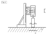
- das erfindungsgemässe Kernbohrsystem mit der Kernbohrmaschine, der Vorschubeinrichtung und der Maschinenhalteeinrichtung zu Beginn eines Kernbohrvorgangs in einen mineralischen Werkstoff;
- Fig. 3
- das erfindungsgemässe Kernbohrsystem mit der Kernbohrmaschine, der Vorschubeinrichtung und der Maschinenhalteeinrichtung mit einer Bohrkrone in dem mineralischen Werkstoff;
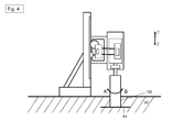
- Fig. 4
- das erfindungsgemässe Kernbohrsystem mit der Kernbohrmaschine, der Vorschubeinrichtung und der Maschinenhalteeinrichtung mit der Bohrkrone beim einem Auftreffen auf ein Armierungseisen in dem mineralischen Werkstoff; und
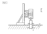
- Fig. 5
- das erfindungsgemässe Kernbohrsystem mit der Kernbohrmaschine, der Vorschubeinrichtung und der Maschinenhalteeinrichtung mit der Bohrkrone nach einem Zerschneiden eines Armierungseisens in dem mineralischen Werkstoff.
-
Fig. 1 zeigt ein Kernbohrsystem 1 als einen Zusammenschluss aus einer Werkzeugmaschine 10, einer Vorschubeinrichtung 30, einem Bohrwerkzeug 50 in Form eine Bohrkrone und eine Maschinenhalteeinrichtung in Form eines Maschinenständers 70. - Die Werkzeugmaschine 10 ist in Form einer Kernbohrmaschine ausgestaltet und enthält ein Gehäuse 12, einen Antrieb 14, ein Getriebe 16, eine erste Steuerungseinheit 18, Sensoren 20 und eine Antriebswelle 22. Der Antrieb 14 ist in Form eines Elektromotors gestaltet. Alternativ kann auch jede andere geeignete Antriebsart gewählt werden.
- Gemäss einer speziellen Ausgestaltungsform der vorliegenden Erfindung kann der Antrieb 14 durch einen Hochfrequenzmotor gebildet sein.
- Die erste Steuerungseinheit 18 ist so ausgestaltet, dass diese sämtliche Parameter der Werkzeugmaschine 10 und insbesondere sämtliche Parameter des Antriebs 14, welche von den Sensoren 20 der Werkzeugmaschine 10 gemessen werden, erfasst. Zu diesen Parametern zählt beispielsweise der eingelegte Gang des Getriebes 16, die Drehzahl des Elektromotors 14, das von dem Elektromotor 14 erzeugte Drehmoment, die Drehzahl des Bohrwerkzeugs 50, die anliegende und/oder abgegebene Leistung des Elektromotors 14, die anliegende Stromstärke des Elektromotors 14, etc.
- Das Gehäuse 12 weist eine obere Seite 12a, eine untere Seite 12b, eine linke Seite 12c und eine rechte Seite 12d auf. Der Antrieb 14 befindet sich im Inneren des Gehäuses 12.
- Die Antriebswelle 22 weist ein erstes Ende 22a und ein zweites Ende 22b auf. Das erste Ende 22a der Antriebswelle 22 ist so mit dem Antrieb 14 verbunden, dass der als Elektromotor ausgestaltete Antrieb 14 die Antriebswelle 22 in eine erste Drehbewegung A oder zweite Drehbewegung B versetzen kann. Das zweite Ende 22b der Antriebswelle 22 ragt an der unteren Seite 12b des Gehäuses 12 aus der Kernbohrmaschine 10 heraus. Des Weiteren weist das Bohrwerkzeug 50 in Gestalt einer zylindrischen Bohrkrone ein erstes Ende 50a und ein zweites Ende 50b auf. Das erste Ende 50a des Bohrwerkzeugs 50 ist drehfest mit dem zweiten Ende 22b der Antriebswelle 22 verbunden. Über die Antriebswelle 22 kann die Werkzeugmaschine 10 das Bohrwerkzeug 50 in die erste Drehbewegung A oder in die zweite Drehbewegung B versetzten.
- Die Vorschubeinrichtung 30 enthält ein Gehäuse 32, in dem ein Vorschubantrieb 34, eine zweite Steuerungseinheit 36, Sensoren 38 sowie ein Antriebsritzel 40 positioniert sind. Die zweite Steuerungseinheit 36 ist so ausgestaltet, dass diese sämtliche Parameter der Vorschubeinrichtung 30 und insbesondere die Parameter des Vorschubantriebs 34, welche von den Sensoren 38 der Vorschubeinrichtung 30 gemessen werden, erfasst. Zu diesen gemessenen Parametern zählt beispielsweise die Vorschubgeschwindigkeit der Vorschubeinrichtung 30 zum Maschinenständer 70 bzw. Werkstück 80, die bereits zurückgelegte Wegstrecke der Vorschubeinrichtung 30 seit Beginn des Bohrvorgangs gemessen von einem zu definierenden Startpunkt (auch Nullpunkt genannt), die Position der Vorschubeinrichtung 30 entlang des Maschinenständers 70, der Drehwinkel des Vorschubantriebs 34, etc.
- Darüber hinaus kann eine Vielzahl an Parametern von der Steuerungseinheit 36 der Vorschubeinrichtung 30 berechnet werden. Die Parameterberechnung erfolgt dabei anhand eines Vergleichs zwischen den von den Sensoren 38 erfassten Parameter, wie z.B. dem Drehwinkel des Antriebsritzels 40, und den vorgegebenen (d.h. voreingestellten) Parametern. Aus der Parameterberechnung kann unter anderem die Vorschubgeschwindigkeit der Vorschubeinrichtung 30 zum Maschinenständer 70, die relative und/oder absolute Position der Vorschubeinrichtung 30, die bereits zurückgelegte Wegstrecke der Vorschubeinrichtung 30 seit Beginn des Bohrvorgangs sowie der Zeitpunkt und/oder die Wegstrecke bis zum Erreichen des Anschlags des Bohrwerkzeugs 50 ermittelt werden.
- Der Vorschubantrieb 34 ist dabei, wie in
Fig. 1 gezeigt, gemäss einer ersten Ausgestaltung in Form eines Elektromotors ausgestaltet. - Der Vorschubantrieb 34 treibt unter Kontrolle der Steuerungseinheit 36 das Antriebsritzel 40 und damit die Vorschubeinrichtung 30 relativ zum Maschinenständer 70 an.
- Die Vorschubeinrichtung 30 ist derartig ausgestaltet, dass diese an den Maschinenständer 70 montiert werden kann (wie nachfolgend beschrieben) und mit Hilfe des Antriebsritzels 40 entlang des Maschinenständers 70 in Pfeilrichtung C bewegt werden kann. Die Sensoren 38 sind in Gestalt von Winkel-, Drehwinkel-, Beschleunigungs-, Geschwindigkeits- bzw. Positionssensoren, und dabei so ausgestaltet, dass diese entweder inkrementell direkt am Vorschubantrieb 34 oder absolut entlang des Maschinenständers 70 die Beschleunigung, die Vorschubgeschwindigkeit, den Winkel, den Drehwinkel sowie die Position der Vorschubeinrichtung 30 erfassen.
- Der Maschinenständer 70 enthält eine Führungsschiene 72, ein Verstrebungselement 74 sowie eine Grundplatte 76. Die Führungsschiene 72 ist so auf der Grundplatte 76 positioniert und von dem Verstrebungselement 74 gestützt, dass die Führungsschiene 72 vertikal oder im vorgegebenen Winkel ausgerichtet ist. Des Weiteren weist die Führungsschiene 72 an einer Seite eine Zahnstange 78 auf. Das Verstrebungselement 74 ist dabei optional und kann gemäss einer alternativen Ausgestaltungsform des Maschinenständers auch weggelassen sein.
- Wie ebenfalls in
Fig. 1 dargestellt, ist das Gehäuse 12 der Werkzeugmaschine 10 an dem Gehäuse 32 der Vorschubeinrichtung 30 befestigt. - Die Vorschubeinrichtung 30 ist so an dem Maschinenständer 70 montiert, dass das Antriebsritzel 40 der Vorschubeinrichtung 30 in die Zahnstange 78 des Maschinenständers 70 eingreift. Wenn unter Kontrolle der Steuerungseinheit 36 der Vorschubantrieb 34 das Antriebsritzel 40 in eine Drehbewegung versetzt, wird die Vorschubeinrichtung 30 reversibel entlang des Maschinenständers 70 in Pfeilrichtung C bzw. C' bewegt. Dadurch, dass die Werkzeugmaschine 10 an der Vorschubeinrichtung 30 befestigt ist, wird durch das Bewegen der Vorschubeinrichtung 30 entlang des Maschinenständers 70 in Pfeilrichtung C auch die Werkzeugmaschine 10 entlang des Maschinenständers 70 in Pfeilrichtung C bewegt. Durch dieses vertikale Bewegen der Werkzeugmaschine 10 wird das an der Werkzeugmaschine 10 befestigte Bohrwerkzeug 50 in Gestalt der zylindrischen Bohrkrone vertikal in das zu bearbeitenden Werkstück 80, d.h. in den Untergrund, befördert, wodurch ein Loch in das Werkstück 80 gebohrt wird. Der Werkstoff 80 ist dabei als mineralischer Werkstoff, insbesondere als Beton mit Armierungseisen 81 ausgestaltet.
- Wie bereits vorstehend beschrieben, messen die jeweiligen Sensoren 38 der Vorschubeinrichtung 30 die Parameter der Vorschubeinrichtung 30. Darüber hinaus messen die jeweiligen Sensoren 38 der Werkzeugmaschine 10 die Parameter der Werkzeugmaschine 10. Wie in
Fig. 3 dargestellt, sind die Vorschubeinrichtung 30 sowie die Werkzeugmaschine 10 durch Verbindungselemente 90 derartig miteinander verbunden, dass sämtliche erfassbare Parameter der Vorschubeinrichtung 30 zu der Werkzeugmaschine 10 gesendet werden können und sämtliche erfassbare Parameter der Werkzeugmaschine 10 zu der Vorschubeinrichtung 30 gesendet werden können. Es liegt somit eine bidirektionale Kommunikation zwischen Vorschubeinrichtung 30 und der Werkzeugmaschine 10 vor. Aufgrund dieser bidirektionalen Kommunikation ist es unter anderem möglich, dass beispielsweise über einen nicht gezeigten Startschalter an der Werkzeugmaschine 10 die Vorschubeinrichtung 30 gestartet und in Betrieb genommen wird. - Darüber hinaus ist es insbesondere möglich, dass der Informationsfluss, d.h. die bidirektionale Übertragung der Parameter, zwischen der Vorschubeinrichtung 30 und der Werkzeugmaschine 10 mit Hilfe eines nicht gezeigten Stromkabels erfolgt. Gemäss einer vorteilhaften Ausgestaltungsform kann dabei die bidirektionale Übertragung der Parameter von dem Stromkabel 100 über die Werkzeugmaschine 10 zu der Vorschubeinrichtung 30 erfolgen.
- Wie bereits vorstehend beschrieben, ist in den
Fig. 1 bis 5 ein Kernbohrsystem 1 schematisch dargestellt und ein Kernbohrvorgang zum Erzeugen eines Bohrlochs 100 in einen mineralischen Werkstoff 80 mit einzelnen Verfahrensschritten illustriert. - In
Fig. 1 ist das Kernbohrsystem 1 zu Beginn eines Kernbohrvorgangs dargestellt. Die Bohrkrone 50 befindet sich hierzu oberhalb in Richtung C' über dem Werkstoff 80. Hierbei wird das Kernbohrsystem 1 mit einem Anbohrmodus betrieben. In dem Anbohrmodus betreibt der Antrieb 14 die Bohrkrone 50 in einer vorbestimmten Anbohrdrehgeschwindigkeit zum Drehen in die Drehrichtung A oder B. Die Anbohrdrehgeschwindigkeit ist abhängig von dem Durchmesser der für den jeweiligen Bohrvorgang verwendeten Bohrkrone 50. - Wie in
Fig. 2 gezeigt, wird anschließend die Bohrkrone 50, die sich in dem Anbohrmodus mit der Anbohrdrehgeschwindigkeit dreht, durch die Vorschubeinrichtung 30 in Richtung C auf den Werkstoff 80 zubewegt. Wenn das zweite Ende 50b der Bohrkrone 50 mit dem Werkstoff 80 in Kontakt tritt, beginnt die Bohrkrone 50, insbesondere die nicht dargestellten Schneidesegmente der Bohrkrone 50, den Werkstoff 80 zu verschneiden und ein Bohrloch 100 zu erzeugen. - Nachdem ein Anbohren des Werkstoffs 80 abgeschlossen ist, d.h. mit der Bohrkrone 50 in Richtung C eine Tiefe von ungefähr 20 mm in den Werkstoff 80 geschnitten wurde, beginnt der restliche Bohrvorgang zur Fertigstellung des Bohrlochs 100. Hierzu wird das Kernbohrsystem 1 von dem Anbohrmodus in einen Bohrmodus umgestellt. Hierzu wird die Drehgeschwindigkeit der Bohrkrone 50 von der relativ niedrigen Anbohrdrehgeschwindigkeit des Anbohrmodus zu der Bohrgeschwindigkeit des Bohrmodus erhöht. Mit dieser Bohrgeschwindigkeit des Bohrmodus wird die Bohrkrone 50 bis zur Fertigstellung des Bohrlochs 100 gedreht und von der Vorschubeinrichtung 30 in Richtung C vorangetrieben.
- Wenn, wie in
Fig. 4 dargestellt, die Bohrkrone 50 auf ein im mineralischen Werkstoff 80 vorkommendes Armierungseisen 81 trifft, wird dies aufgrund von sich verändernden Bohrparametern durch das Kernbohrsystem 1 detektiert. Als Folge daraus wird das Kernbohrsystem 1 von dem Bohrmodus in einen Armierungseisenmodus (sog. Iron Boost) umgestellt. In dem Armierungseisenmodus werden vorbestimmte Bohrparameter des Kernbohrsystems 1 auf die geänderten Bedingungen bei dem Zerschneiden eines Armierungseisens verändert bzw. angepasst. So wird beispielsweise die Bohrdrehgeschwindigkeit auf eine Armierungseisendrehgeschwindigkeit reduziert sowie das von dem Antrieb 14 erzeugte und auf die Bohrkrone 50 übertragende Drehmoment erhöht. Durch die für den Armierungseisenmodus angepassten Bohrparameter auf vorbestimmte Werte kann ein Armierungseisen schneller und effizienter zerschnitten werden. Insgesamt wird mit Hilfe des Armierungseisenmodus der gesamte Kernbohrvorgang ebenfalls schneller und effizienter. - Wenn anhand von sich entsprechend verändernden Bohrparametern durch das Kernbohrsystem 1 detektiert wird, dass das Armierungseisen 81 durch die Bohrkrone 50 durchschnitten wurde und im Anschluss daran wieder lediglich der mineralische Werkstoff 80 durch die Bohrkrone 50 zerschnitten wird (vgl.
Fig. 5 ), wird das Kernbohrsystem 1 von dem Armierungseisenmodus wieder in den Bohrmodus umgestellt. Hierzu wird beispielsweise die Bohrdrehgeschwindigkeit auf Bohrgeschwindigkeit erhöht sowie das von dem Antrieb 14 erzeugte und auf die Bohrkrone 50 übertragende Drehmoment reduziert. - Nachdem die Bohrkrone 50 entweder die gewünschte Bohrtiefe in Richtung C in den mineralischen Werkstoff 80 geschnitten hat oder ein Durchbruch durch den mineralischen Werkstoff 80 erreicht wurde, wird das Kernbohrsystem von dem Bohrmodus in einen Rückfahrmodus umgestellt.
- Das Erreichen der gewünschten Bohrlochtiefe kann anhand eines Erreichens eines vorbestimmten Schwellwerts für wenigstens einen entsprechenden vorbestimmten Bohrparameter bestimmt werden. Bei den Bohrparametern kann es sich z.B. um die Vorschubgeschwindigkeit der Vorschubeinrichtung 30, die Drehzahl der Antriebs 14, die Drehzahl der Bohrkrone 50, die Motorstromstärke des Antriebs 14, das von dem Antrieb 14 erzeugte und auf die Bohrkrone 50 übertragende Drehmoment oder dergleichen handeln. So wird beispielsweise von dem Kernbohrsystem 1 anhand einer abnehmenden Vorschubgeschwindigkeit der Vorschubeinrichtung 30, eines reduzierten Drehmoments des Antriebs 14 und einer erhöhten Drehzahl des Antriebs 14 sowie der Bohrkrone 50 das Erreichen einer vorbestimmten Bohrtiefe oder ein Durchbruch ermittelt.
- Mit Hilfe des Rückfahrmodus kann die Möglichkeit die Bohrkrone und/oder die Kernbohrmaschine bei der Entnahme der Bohrkrone aus dem Bohrloch 100 zu beschädigen reduziert werden.
- Hierzu wird für die Einstellung des Kernbohrsystems in den Rückfahrmodus die Drehzahl der Bohrkrone 50 auf eine Rückfahrdrehgeschwindigkeit eingestellt und die Bohrkrone 50 von der Vorschubeinrichtung 30 in Richtung C' aus dem Bohrloch 100 gezogen. Die Rückfahrdrehgeschwindigkeit entspricht dabei einem Vielfachen der Anbohrdrehgeschwindigkeit der Bohrkrone zu Beginn des Kernbohrvorgangs. Wie bereits vorstehend beschrieben handelt es sich bei der Anbohrdrehgeschwindigkeit um die Drehgeschwindigkeit, die von dem Kernbohrsystem 1 für die Bohrkrone 50 bei dem ersten Kontakt mit dem mineralischen Werkstoff 80 und bis zum Erreichen einer Bohrtiefe von ungefähr 20 mm festgelegt wird. Als besonders vorteilhaft hat sich dabei ein Wert für die Rückfahrdrehgeschwindigkeit herausgestellt, der einem 3- bis 4-fachen der Anbohrdrehgeschwindigkeit der Bohrkrone bei Beginn des Bohrvorgangs entspricht. Alternativ kann die Rückfahrdrehgeschwindigkeit auch dem halben Wert der Leerlaufdrehgeschwindigkeit entsprechen.
Claims (10)
- Regelverfahren zur Verwendung eines Kernbohrsystems (1) enthaltend eine Kernbohrmaschine (10) und eine Vorschubeinrichtung (30) zum Antreiben der Kernbohrmaschine (10) entlang einer Maschinenhalteeinrichtung (70),
gekennzeichnet durch die folgenden Verfahrensschritte- Bestimmen des Endes eines Kernbohrvorgangs anhand eines Erreichens eines vorbestimmten Schwellwerts für wenigstens einen entsprechenden vorbestimmten Bohrparameter; und- Auswählen eines Rückfahrmodus zum Zurückfahren eines Bohrwerkzeugs (50) aus einem Bohrloch (100) mit einer Rückfahrdrehgeschwindigkeit, welche einem Vielfachen einer vorbestimmten Anbohrdrehgeschwindigkeit des Bohrwerkzeugs (50) zu Beginn des Kernbohrvorgangs entspricht. - Verfahren nach Anspruch 1,
wobei die Rückfahrdrehgeschwindigkeit einem Vielfachen der Anbohrdrehgeschwindigkeit entspricht. - Verfahren nach Anspruch 1,
wobei die Rückfahrdrehgeschwindigkeit einem 3- bis 4-fachen der Anbohrdrehgeschwindigkeit entspricht. - Verfahren nach Anspruch 1,
wobei die Rückfahrdrehgeschwindigkeit dem halben Wert der Leerlaufdrehgeschwindigkeit entspricht. - Verfahren nach wenigstens einem der Ansprüche 1 bis 4,
wobei die Anbohrdrehgeschwindigkeit von dem Durchmesser des verwendeten Bohrwerkzeugs (50) abhängig ist. - Verfahren nach wenigstens einem der Ansprüche 1 bis 5,
wobei der Bohrparameter einem Drehzahlwert eines Antriebs (14) der Kernbohrmaschine (10), einem von dem Antrieb (14) erzeugten und auf das Bohrwerkzeug (50) übertragenen Drehmomentwert oder einem Stromstärkenwert des Antriebs (14) entspricht. - Verfahren nach wenigstens einem der Ansprüche 1 bis 6,
wobei der vorbestimmte Schwellwert einem vorbestimmten prozentualen Anteil an dem entsprechenden Bohrparameter entspricht. - Vorschubeinrichtung zum Antreiben einer Kernbohrmaschine (10) entlang einer Maschinenhalteeinrichtung (70) zur Verwendung des Verfahrens nach wenigstens einem der Ansprüche 1 bis 7.
- Kernbohrmaschine zur Verwendung des Verfahrens nach wenigstens einem der Ansprüche 1 bis 7.
- Kernbohrsystem (1) enthaltend eine Kernbohrmaschine (10) und eine Vorschubeinrichtung (30) zum Antreiben der Kernbohrmaschine (10) entlang einer Maschinenhalteeinrichtung (70) zur Verwendung des Verfahrens nach wenigstens einem der Ansprüche 1 bis 7.
Priority Applications (5)
| Application Number | Priority Date | Filing Date | Title |
|---|---|---|---|
| EP15165313.6A EP3088151A1 (de) | 2015-04-28 | 2015-04-28 | Rückfahrmodus für kernbohrsysteme |
| RU2017141170A RU2711170C2 (ru) | 2015-04-28 | 2016-04-22 | Режим возврата для систем колонкового сверления |
| EP16720074.0A EP3288733A1 (de) | 2015-04-28 | 2016-04-22 | Rückfahrmodus für kernbohrsysteme |
| PCT/EP2016/059020 WO2016173943A1 (de) | 2015-04-28 | 2016-04-22 | Rückfahrmodus für kernbohrsysteme |
| US15/569,354 US10583499B2 (en) | 2015-04-28 | 2016-04-22 | Reversing mode for core drilling systems |
Applications Claiming Priority (1)
| Application Number | Priority Date | Filing Date | Title |
|---|---|---|---|
| EP15165313.6A EP3088151A1 (de) | 2015-04-28 | 2015-04-28 | Rückfahrmodus für kernbohrsysteme |
Publications (1)
| Publication Number | Publication Date |
|---|---|
| EP3088151A1 true EP3088151A1 (de) | 2016-11-02 |
Family
ID=53039276
Family Applications (2)
| Application Number | Title | Priority Date | Filing Date |
|---|---|---|---|
| EP15165313.6A Withdrawn EP3088151A1 (de) | 2015-04-28 | 2015-04-28 | Rückfahrmodus für kernbohrsysteme |
| EP16720074.0A Withdrawn EP3288733A1 (de) | 2015-04-28 | 2016-04-22 | Rückfahrmodus für kernbohrsysteme |
Family Applications After (1)
| Application Number | Title | Priority Date | Filing Date |
|---|---|---|---|
| EP16720074.0A Withdrawn EP3288733A1 (de) | 2015-04-28 | 2016-04-22 | Rückfahrmodus für kernbohrsysteme |
Country Status (4)
| Country | Link |
|---|---|
| US (1) | US10583499B2 (de) |
| EP (2) | EP3088151A1 (de) |
| RU (1) | RU2711170C2 (de) |
| WO (1) | WO2016173943A1 (de) |
Cited By (4)
| Publication number | Priority date | Publication date | Assignee | Title |
|---|---|---|---|---|
| FR3078908A1 (fr) * | 2018-03-16 | 2019-09-20 | Safran Nacelles | Dispositif de mesure de la longueur percer dans un assemblage aeronautique |
| EP3919208A1 (de) * | 2020-06-02 | 2021-12-08 | Hilti Aktiengesellschaft | Bohrsystem, das ein kernbohrgerät und eine vorschubvorrichtung umfasst, und verfahren zur erkennung und beseitigung einer blockade einer bohrkrone |
| WO2022043151A1 (de) * | 2020-08-26 | 2022-03-03 | Hilti Aktiengesellschaft | Werkzeugmaschine zur bearbeitung eines untergrunds und verfahren zur analyse einer zusammensetzung des untergrunds |
| EP4289533A1 (de) * | 2022-06-07 | 2023-12-13 | Hilti Aktiengesellschaft | Verfahren zum betrieb einer werkzeugmaschine und werkzeugmaschine |
Families Citing this family (3)
| Publication number | Priority date | Publication date | Assignee | Title |
|---|---|---|---|---|
| CN208644148U (zh) | 2018-04-24 | 2019-03-26 | 米沃奇电动工具公司 | 电钻台架 |
| CN109915014B (zh) * | 2019-04-23 | 2024-02-09 | 安徽理工大学 | 用于链条进给结构钻机的钻孔自动计长装置及使用方法 |
| DE102019112999A1 (de) * | 2019-05-16 | 2020-11-19 | C. & E. Fein Gmbh | Verfahren zum Betreiben einer Kernbohrmaschine sowie Kernbohrmaschine und Kernbohrkrone zur Durchführung des Verfahrens |
Citations (5)
| Publication number | Priority date | Publication date | Assignee | Title |
|---|---|---|---|---|
| US5558476A (en) * | 1992-07-16 | 1996-09-24 | Hitachi Koki Co., Ltd. | Dual-motor-driven drilling machine and method of controlling currents flowing in motors |
| DE102007053350A1 (de) * | 2007-10-30 | 2009-05-07 | Chiron-Werke Gmbh & Co Kg | Verfahren zur spanabhebenden Bearbeitung von Werkstücken |
| CN102294499A (zh) * | 2011-07-19 | 2011-12-28 | 深圳市大族激光科技股份有限公司 | 一种pcb板钻机的钻孔加工方法 |
| DE102013205827A1 (de) * | 2013-04-03 | 2014-10-09 | Hilti Aktiengesellschaft | Vorschubeinrichtung |
| EP2835198A1 (de) * | 2013-08-09 | 2015-02-11 | HILTI Aktiengesellschaft | Intuitive, adaptive Anbohrfunktion |
Family Cites Families (7)
| Publication number | Priority date | Publication date | Assignee | Title |
|---|---|---|---|---|
| US3248629A (en) * | 1960-03-14 | 1966-04-26 | Dyna Systems Inc | Motor control system and torque indicating means |
| US3894809A (en) * | 1973-07-16 | 1975-07-15 | Hollins J R | Drill press arrangement |
| SU739219A1 (ru) | 1977-12-21 | 1980-06-05 | Киевский Ордена Ленина Геологоразведочный Трест "Киевгеология" | Система автоматического управлени процессом механического колонкового бурени |
| RU2059464C1 (ru) | 1991-06-28 | 1996-05-10 | Арендное предприятие "Центральный научно-исследовательский и проектно-экспериментальный институт организации, механизации и технической помощи строительству" | Сверлильный станок |
| US5628594A (en) * | 1995-08-14 | 1997-05-13 | Fetty; James R. | Horizontal insert for universal turret milling machines |
| DE10304405B4 (de) * | 2003-02-01 | 2012-10-04 | Hilti Aktiengesellschaft | Verfahren zur Regelung einer Kernbohrmaschine |
| EP2826609A1 (de) | 2013-07-18 | 2015-01-21 | HILTI Aktiengesellschaft | Automatische Anbohrhilfe |
-
2015
- 2015-04-28 EP EP15165313.6A patent/EP3088151A1/de not_active Withdrawn
-
2016
- 2016-04-22 US US15/569,354 patent/US10583499B2/en active Active
- 2016-04-22 WO PCT/EP2016/059020 patent/WO2016173943A1/de active Application Filing
- 2016-04-22 EP EP16720074.0A patent/EP3288733A1/de not_active Withdrawn
- 2016-04-22 RU RU2017141170A patent/RU2711170C2/ru active
Patent Citations (5)
| Publication number | Priority date | Publication date | Assignee | Title |
|---|---|---|---|---|
| US5558476A (en) * | 1992-07-16 | 1996-09-24 | Hitachi Koki Co., Ltd. | Dual-motor-driven drilling machine and method of controlling currents flowing in motors |
| DE102007053350A1 (de) * | 2007-10-30 | 2009-05-07 | Chiron-Werke Gmbh & Co Kg | Verfahren zur spanabhebenden Bearbeitung von Werkstücken |
| CN102294499A (zh) * | 2011-07-19 | 2011-12-28 | 深圳市大族激光科技股份有限公司 | 一种pcb板钻机的钻孔加工方法 |
| DE102013205827A1 (de) * | 2013-04-03 | 2014-10-09 | Hilti Aktiengesellschaft | Vorschubeinrichtung |
| EP2835198A1 (de) * | 2013-08-09 | 2015-02-11 | HILTI Aktiengesellschaft | Intuitive, adaptive Anbohrfunktion |
Cited By (5)
| Publication number | Priority date | Publication date | Assignee | Title |
|---|---|---|---|---|
| FR3078908A1 (fr) * | 2018-03-16 | 2019-09-20 | Safran Nacelles | Dispositif de mesure de la longueur percer dans un assemblage aeronautique |
| EP3919208A1 (de) * | 2020-06-02 | 2021-12-08 | Hilti Aktiengesellschaft | Bohrsystem, das ein kernbohrgerät und eine vorschubvorrichtung umfasst, und verfahren zur erkennung und beseitigung einer blockade einer bohrkrone |
| WO2022043151A1 (de) * | 2020-08-26 | 2022-03-03 | Hilti Aktiengesellschaft | Werkzeugmaschine zur bearbeitung eines untergrunds und verfahren zur analyse einer zusammensetzung des untergrunds |
| EP4289533A1 (de) * | 2022-06-07 | 2023-12-13 | Hilti Aktiengesellschaft | Verfahren zum betrieb einer werkzeugmaschine und werkzeugmaschine |
| WO2023237364A1 (de) * | 2022-06-07 | 2023-12-14 | Hilti Aktiengesellschaft | Verfahren zum betrieb einer werkzeugmaschine und werkzeugmaschine |
Also Published As
| Publication number | Publication date |
|---|---|
| RU2017141170A (ru) | 2019-05-28 |
| WO2016173943A1 (de) | 2016-11-03 |
| US20180297126A1 (en) | 2018-10-18 |
| US10583499B2 (en) | 2020-03-10 |
| RU2711170C2 (ru) | 2020-01-15 |
| RU2017141170A3 (de) | 2019-11-01 |
| EP3288733A1 (de) | 2018-03-07 |
Similar Documents
| Publication | Publication Date | Title |
|---|---|---|
| EP3288733A1 (de) | Rückfahrmodus für kernbohrsysteme | |
| EP3081737B1 (de) | Bohrgerät zum erstellen einer verrohrten bohrung und verfahren zum betreiben eines bohrgerätes | |
| EP3288485B1 (de) | Intelligente oberflächenerkennung und kernbohrbeginn | |
| EP3288717B1 (de) | Regelverfahren zur verwendung eines kernbohrsystems und kernbohrsystem | |
| EP3113910B1 (de) | Adaptive getriebeschaltung | |
| EP3113911B1 (de) | Adaptive leistungsanzeige | |
| WO2016173941A1 (de) | Adaptive generierung von bohrparametern beim automatisierten kernbohren | |
| EP3299523B1 (de) | Verfahren und baugerät zur baugrundbearbeitung | |
| DE102013205827A1 (de) | Vorschubeinrichtung | |
| DE19644694A1 (de) | Vorrichtung zur Steuerung einer Bohr-Gewindeschneide-Maschine | |
| EP3022027B1 (de) | Verfahren zum steuern einer werkzeugmaschine | |
| EP3084537B1 (de) | Verfahren zur steuerung eines gerätesystems mit einem werkzeuggerät und einer motorischen vorschubeinrichtung | |
| EP3030368B1 (de) | Intuitive, adaptive anbohrfunktion | |
| EP0744526A1 (de) | Verfahren zum Steuern eines Bohrwerkzeugs | |
| DE202008003538U1 (de) | Bohreinrichtung zur Herstellung einer Präzisions-Durchgangsbohrung | |
| EP4124413A1 (de) | Verfahren zum steuern und regeln einer werkzeugmaschine | |
| EP3756823A1 (de) | Verfahren zur erkennung eines zustands einer werkzeugmaschine, sowie eine werkzeugmaschine | |
| EP4316736A1 (de) | Verfahren zum steuern und regeln einer werkzeugmaschine und erfassungsvorringung sowie system zur durchführung des verfahrens | |
| EP3429788A1 (de) | Verfahren zum betreiben einer werkzeugmaschine und werkzeugmaschine betreibbar mit dem vefahren | |
| DE202010010848U1 (de) | Bohrautomat | |
| EP3664059A1 (de) | Verfahren zum betreiben eines systems und system |
Legal Events
| Date | Code | Title | Description |
|---|---|---|---|
| PUAI | Public reference made under article 153(3) epc to a published international application that has entered the european phase |
Free format text: ORIGINAL CODE: 0009012 |
|
| AK | Designated contracting states |
Kind code of ref document: A1 Designated state(s): AL AT BE BG CH CY CZ DE DK EE ES FI FR GB GR HR HU IE IS IT LI LT LU LV MC MK MT NL NO PL PT RO RS SE SI SK SM TR |
|
| AX | Request for extension of the european patent |
Extension state: BA ME |
|
| STAA | Information on the status of an ep patent application or granted ep patent |
Free format text: STATUS: THE APPLICATION IS DEEMED TO BE WITHDRAWN |
|
| 18D | Application deemed to be withdrawn |
Effective date: 20170503 |