EP3737593B1 - Wischblattvorrichtung - Google Patents
Wischblattvorrichtung Download PDFInfo
- Publication number
- EP3737593B1 EP3737593B1 EP18800902.1A EP18800902A EP3737593B1 EP 3737593 B1 EP3737593 B1 EP 3737593B1 EP 18800902 A EP18800902 A EP 18800902A EP 3737593 B1 EP3737593 B1 EP 3737593B1
- Authority
- EP
- European Patent Office
- Prior art keywords
- channel
- spoiler
- unit
- wiper
- channel element
- Prior art date
- Legal status (The legal status is an assumption and is not a legal conclusion. Google has not performed a legal analysis and makes no representation as to the accuracy of the status listed.)
- Active
Links
Images


Classifications
-
- B—PERFORMING OPERATIONS; TRANSPORTING
- B60—VEHICLES IN GENERAL
- B60S—SERVICING, CLEANING, REPAIRING, SUPPORTING, LIFTING, OR MANOEUVRING OF VEHICLES, NOT OTHERWISE PROVIDED FOR
- B60S1/00—Cleaning of vehicles
- B60S1/02—Cleaning windscreens, windows or optical devices
- B60S1/46—Cleaning windscreens, windows or optical devices using liquid; Windscreen washers
- B60S1/48—Liquid supply therefor
- B60S1/52—Arrangement of nozzles; Liquid spreading means
- B60S1/522—Arrangement of nozzles; Liquid spreading means moving liquid spreading means, e.g. arranged in wiper arms
- B60S1/524—Arrangement of nozzles; Liquid spreading means moving liquid spreading means, e.g. arranged in wiper arms arranged in wiper blades
-
- B—PERFORMING OPERATIONS; TRANSPORTING
- B60—VEHICLES IN GENERAL
- B60S—SERVICING, CLEANING, REPAIRING, SUPPORTING, LIFTING, OR MANOEUVRING OF VEHICLES, NOT OTHERWISE PROVIDED FOR
- B60S1/00—Cleaning of vehicles
- B60S1/02—Cleaning windscreens, windows or optical devices
- B60S1/04—Wipers or the like, e.g. scrapers
- B60S1/32—Wipers or the like, e.g. scrapers characterised by constructional features of wiper blade arms or blades
- B60S1/38—Wiper blades
- B60S1/3806—Means, or measures taken, for influencing the aerodynamic quality of the wiper blades
- B60S1/381—Spoilers mounted on the squeegee or on the vertebra
Definitions
- a wiper blade device for a windshield wiper with a spoiler unit has already been proposed, which has at least one soft spoiler component and at least one hard spoiler component, the hard spoiler component at least partially forming a receiving area for a spring rail, and with a spray unit.
- EP 2 415 645 A1 discloses a similar wiper blade device.
- WO 2007/000346 A1 discloses a wiper blade device according to the preamble of claim 1.
- the invention is based on a wiper blade device for a windshield wiper with a spoiler unit that has at least one soft spoiler component and at least one hard spoiler component, the hard spoiler component at least partially forming a receiving area for a spring rail, and with a spray unit.
- the spray unit has at least one first channel element that is at least partially molded onto the hard spoiler component.
- the spoiler unit is preferably made from at least two different materials, in particular from at least two different plastics.
- the soft spoiler component of the spoiler unit is preferably made of a first material, in particular a first plastic.
- the hard spoiler component of the spoiler unit is preferably made from a second material, in particular from a second plastic.
- the second material is harder, in particular more torsion-resistant, than the first material.
- the spoiler unit is preferably produced in a coextrusion process, in which in particular the first material and the second material are brought together.
- the soft spoiler component and the hard spoiler component are integrally connected to one another, in particular designed in one piece.
- the soft spoiler component preferably forms a spoiler extension, which is provided in particular to generate a contact pressure as a result of a relative wind, which is aligned in the direction of a surface to be wiped, in particular a windshield.
- the soft spoiler component can preferably be configured asymmetrically, in particular viewed along a main extension direction of the wiper blade device.
- a "main extension direction" of an object is to be understood in particular as a direction which runs parallel to a longest edge of a smallest geometric cuboid which just about completely encloses the object.
- the soft spoiler component is preferably provided for generating a contact pressure from a headwind.
- the receiving area for the spring rail is designed in particular as a recess in the hard spoiler component.
- the receiving area preferably has a polygonal, in particular rectangular, cross section.
- the receiving area preferably extends at least essentially along an entire extent of the wiper blade device along the main direction of extent of the wiper blade device.
- the receiving area is preferably provided for at least partially receiving a wiper strip. “Provided” is to be understood in particular as being specially designed and/or equipped. The fact that an object is provided for a specific function is to be understood in particular to mean that the object fulfills and/or executes this specific function in at least one application and/or operating state.
- the spray unit in particular the first channel element of the spray unit, is preferably provided for dispensing and/or guiding a cleaning fluid, in particular a cleaning water.
- the spray unit preferably has a multiplicity of first channel elements.
- the first channel elements are preferably arranged along the main extension direction of the wiper blade device, in particular equidistant from one another.
- the first Channel elements designed as tubular recesses.
- the first channel elements are partially arranged inside the hard spoiler component, preferably completely inside the hard spoiler component.
- at least discharge openings of the first channel elements are arranged entirely within the hard spoiler component.
- the configuration of the wiper blade device according to the invention advantageously makes it possible to provide a wiper blade device with particularly dimensionally stable first channel elements.
- the first channel elements can be designed to be at least essentially resistant to closure, in particular resistant to calcification.
- a low-maintenance wiper blade device can advantageously be provided, which enables a particularly precise dispensing of a cleaning fluid.
- the first channel element which is at least partially formed on, at least partially forms a spray nozzle element of the spray unit. All of the first channel elements that are at least partially molded on preferably form at least partially spray nozzle elements of the spray unit.
- the first channel elements preferably form spray nozzle elements in a region of the dispensing openings of the first channel elements.
- the cleaning fluid is preferably dispensed through the first channel elements forming spray nozzle elements under an overpressure which is in particular higher than an ambient pressure of an environment surrounding the wiper blade device.
- the spray nozzle elements can be designed in such a way that the cleaning fluid is atomized when it is discharged from the spray nozzle elements.
- the cleaning fluid can be dispensed in a targeted manner and at the same time over a large area.
- the first channel element has a main extension direction at least essentially parallel to a vertical extension direction of the spoiler unit.
- all the first channel elements have a main extension direction at least essentially parallel to the vertical extension direction of the spoiler unit.
- the vertical extension direction of the spoiler unit runs in particular at least essentially perpendicularly to a main extension plane of the receiving area for the spring rail.
- "Essentially parallel” is to be understood in particular as meaning an orientation of a direction relative to a reference direction, in particular in a plane, with the direction relative to the reference direction deviating in particular by less than 8°, advantageously less than 5° and particularly advantageously less than 2 ° has.
- the expression “essentially perpendicular” is intended to define in particular an alignment of a direction relative to a reference direction, with the direction and the reference direction, viewed in particular in one plane, enclosing an angle of 90° and the angle has a maximum deviation of, in particular, less than 8° , advantageously less than 5° and particularly advantageously less than 2°.
- a "main extension plane" of an object is to be understood in particular as a plane which is parallel to a largest side face of an imaginary cuboid which just about completely encloses the structural unit and in particular runs through the center point of the cuboid.
- the main extension direction of the first channel elements preferably runs at least essentially perpendicular to a surface of the motor vehicle window when the wiper blade device is mounted on a motor vehicle window.
- the cleaning fluid can be dispensed at least substantially perpendicularly onto the motor vehicle window.
- the first channel element is arranged at least partially overlapping the receiving area of the spring rail in a vertical extension direction of the spoiler unit. All of the first channel elements are preferably arranged in the vertical direction of extension of the spoiler unit so that they at least partially overlap the receiving area of the spring rail.
- the first channel elements have a main extension direction along a vertical extension direction of the receiving area.
- the vertical direction of extent of the receiving area runs in particular at least essentially parallel to the vertical direction of extent of the spoiler unit.
- the main extension direction of the first channel elements preferably runs at least essentially parallel to the vertical extension direction of the receiving area. Precise guidance of the cleaning fluid through the first channel elements can advantageously be achieved.
- the first channel element is arranged at least partially offset in a direction of transverse extent of the spoiler unit with respect to the receiving area of the spring rail. All first channel elements are preferably arranged at least partially offset in the direction of transverse extension of the spoiler unit with respect to the receiving area of the spring rail.
- the direction of transverse extension of the spoiler unit runs in particular at least essentially perpendicular to the main direction of extension of the wiper blade device and in particular at least essentially perpendicular to the direction of vertical extension of the spoiler unit.
- the first channel elements are preferably at least partially separated from the receiving area by the hard spoiler component in the direction of transverse extension of the spoiler unit.
- the first channel elements can be completely separated from the receiving area by the hard spoiler component in the direction of transverse extent of the spoiler unit.
- the first channel elements are at least partially separated from the receiving area by the soft spoiler component in the direction of transverse extent of the spoiler unit.
- a spatial separation between the first channel elements and the receiving area can advantageously be achieved.
- the first channel elements can advantageously be made robust.
- the soft spoiler component at least partially forms at least one channel of the spray unit, which is directly connected to the first channel element.
- the soft spoiler component at least partially forms at least one channel of the spray unit, which is directly connected to all of the first channel elements.
- the channel preferably runs at least essentially parallel to the main direction of extension of the wiper blade device.
- the channel preferably extends at least essentially along the entire extent of the spoiler unit along the main direction of extent of the wiper blade device.
- the channel is in particular designed as a preferably tubular recess in the soft spoiler component.
- the channel is preferably provided for a passage of the cleaning fluid.
- the cleaning fluid can be conveyed, in particular pumped, through the channel, for example from a reservoir unit of a motor vehicle or the like.
- the channel preferably has exactly two end pieces.
- the channel is at least at a first end portion sealed substantially fluid-tight.
- the channel is preferably connected at a second end piece to a feed element, such as a hose, a pipe or the like.
- the cleaning fluid for example from the reservoir unit, is fed to the channel through the feed element.
- the duct is preferably arranged above the first duct elements, viewed along the vertical extension direction of the spoiler unit.
- the cleaning fluid which is under an overpressure, in particular in comparison to an ambient pressure of the environment surrounding the wiper blade device, is preferably pressed out of the channel into the first channel elements and discharged through the first channel elements.
- the first channel elements are preferably arranged at least essentially along the entire channel, in particular equidistant from one another. Efficient supply of the cleaning fluid to the first channel elements can advantageously be made possible.
- the first channel element be delimited by a wall of the receiving area of the spring rail, the wall at least partially delimiting the receiving area on a side of the wall facing away from the spray nozzle element. All of the first channel elements are preferably delimited by the wall of the receiving area of the spring rail, with the wall at least partially delimiting the receiving area on the side of the wall facing away from the spray nozzle elements.
- the wall delimits the receiving area on the side of the wall facing away from the spray nozzle elements, preferably along the direction of transverse extent of the spoiler unit.
- the first channel elements can be formed at least partially, preferably along a complete vertical extent of the first channel elements, on the wall of the receiving area.
- the vertical extent of the first channel elements is in particular an extent of the first channel elements along the main direction of extent of the first channel elements.
- the spray unit has at least one second channel element, which is located on a channel element facing away from the first Side of the recording area is arranged.
- the spray unit preferably has a multiplicity of second channel elements which are arranged on the side of the receiving area which is remote from the first channel element.
- the second channel elements are designed at least essentially analogously to the first channel elements.
- the second channel elements are preferably provided for dispensing the cleaning fluid.
- the spray unit preferably comprises a second channel, which is arranged in particular on the side of the receiving region which is remote from the first channel elements.
- the second channel is preferably designed at least essentially analogously to the channel connected to the first channel elements.
- the second channel is directly connected to the second channel elements.
- the second channel is preferably provided for a passage of the cleaning fluid.
- the second channel elements and the second channel are arranged at least essentially mirror-symmetrically to the first channel elements and the channel connected to the first channel elements around the receiving area.
- Cleaning fluid can advantageously be dispensed on two sides of the receiving area, in particular simultaneously.
- the cleaning fluid can advantageously be dispensed spatially in front of a wiper lip of a windshield wiper. A particularly thorough cleaning of a motor vehicle window can advantageously be achieved.
- the invention is based on a wiper blade with a wiper blade device according to the invention.
- the wiper blade preferably includes other components that are necessary in particular for operation of the wiper blade.
- the wiper blade comprises the spring rail, which is pushed in particular into the receiving area.
- the spring rail is preferably formed at least partially from spring steel.
- the spring rail In an unloaded state, the spring rail preferably essentially has the shape of a curved rod and particularly advantageously a flattened curved rod.
- a curvature of the spring rail along a longitudinal extent in an unloaded state is particularly advantageously greater than a curvature of a vehicle surface of a motor vehicle, in particular a motor vehicle window, over which the spring rail is guided in at least one operating state.
- an “extension” of an element is intended in particular to mean a maximum distance between two Points of a perpendicular projection of the element onto a plane.
- the wiper blade comprises a wiper strip, which is in particular pushed at least partially into the receiving area.
- a “wiper strip” is to be understood in particular as a unit made of an elastic material with a wiper lip, which is intended to be moved in contact over the surface to be cleaned in order to clean a surface to be cleaned, in particular a window surface, preferably a vehicle window will.
- the wiper strip is preferably made of a natural or artificial elastomer, in particular rubber.
- a low-maintenance wiper blade can advantageously be provided, which enables a cleaning fluid to be dispensed particularly precisely.
- the invention is based on a windshield wiper with a wiper blade according to the invention.
- the windshield wiper preferably includes other components that are required in particular for operation of the windshield wiper.
- the windshield wiper includes an adapter unit for mounting the wiper blade on a windshield wiper drive unit of a motor vehicle.
- a windshield wiper with an integrated cleaning fluid dispensing function can advantageously be provided.
- the wiper blade device according to the invention, the wiper blade according to the invention, the spoiler unit according to the invention, the spray unit according to the invention and/or the windscreen wiper according to the invention should/should not be limited to the application and embodiment described above.
- the spoiler unit according to the invention, the spray unit according to the invention and/or the windshield wiper according to the invention can/can have a number of individual elements, components and units that differs from the number specified here in order to fulfill a function described herein.
- values lying within the specified limits should also be considered disclosed and can be used as desired.
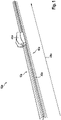
- FIG 1 shows a windshield wiper 12a in a perspective view.
- the wiper 12a includes a wiper blade 42a.
- the windshield wiper 12a includes an adapter unit 44a for mounting the wiper blade 42a on a windshield wiper drive unit of a motor vehicle.
- the wiper blade 42a has a wiper blade device 10a.
- the wiper blade 42a has a spring rail, not shown in any more detail.
- the wiper blade 42a has a wiper strip 46a. The spring rail and part of the wiper strip 46a are pushed into a receiving area 20a of the wiper blade device 10a, which is not shown in any more detail.
- FIG 2 shows the wiper blade device 10a for the windshield wiper 12a in a schematic sectional view.
- a sectional plane shown is perpendicular to a main extension direction 48a of the wiper blade device 10a (cf. figure 1 ).
- the wiper blade device 10a includes a spoiler unit 14a.
- the spoiler unit 14a has a soft spoiler component 16a and a hard spoiler component 18a.
- the soft spoiler component 16a is along a vertical extension direction 28a of the spoiler unit 14a viewed above the hard spoiler component 18a.
- the soft spoiler component 16a and the hard spoiler component 18a are made of different plastics. The different plastics are brought together in a coextrusion process.
- the soft spoiler component 16a and the hard spoiler component 18a are formed in one piece.
- the hard spoiler component 18a partially forms the receiving area 20a for the spring rail.
- the receiving area 20a is designed as a recess in the hard spoiler component 18a.
- the receiving area 20a has a rectangular cross section.
- the receiving area 20a extends along the entire main extension direction 48a of the wiper blade device 10a.
- the soft spoiler component 16a forms a spoiler extension.
- the soft spoiler component 16a is configured asymmetrically viewed along the main extension direction 48a of the wiper blade device 10a.
- the soft spoiler component 16a is provided for generating a contact pressure from a relative wind.
- the wiper blade device 10a has a spray unit 22a.
- the spray unit 22a includes a first channel element 24a.
- the first channel element 24a is molded onto the hard spoiler component 18a.
- the first channel element 24a is completely formed onto the hard spoiler component 18a.
- the spray unit 22a has a multiplicity of first channel elements 24a.
- the first channel elements 24a are arranged along the main extension direction 48a of the wiper blade device 10a.
- the first channel elements 24a are arranged equidistantly from one another along the main extension direction 48a of the wiper blade device 10a.
- the first channel element 24a is formed as a tubular recess.
- the first channel member 24a is formed as a tubular recess within the hard spoiler component 18a.
- the first channel element 24a is provided for dispensing and/or guiding a cleaning fluid.
- the cleaning fluid is designed as a cleaning water.
- the first channel element 24a is partially designed as a spray nozzle element 26a of the spray unit 22a.
- the first channel element 24a is designed as a spray nozzle element 26a at a discharge opening of the first channel element 24a.
- the cleaning fluid is discharged through the spray nozzle element 26a under an overpressure.
- the overpressure is higher than an ambient pressure of an environment surrounding the wiper blade device 10a.
- the first channel element 24a has a main extension direction essentially parallel to the vertical extension direction 28a of the spoiler unit 14a.
- the main extension direction of the first channel element 24a runs essentially perpendicular to a surface of the motor vehicle window when the windshield wiper 12a is mounted on a motor vehicle window.
- the first channel element 24a is arranged in the vertical extension direction 28a of the spoiler unit 14a so that it overlaps with the receiving region 20a of the spring rail.
- the first channel element 24a is arranged in the vertical extension direction 28a of the spoiler unit 14a so that it completely overlaps with the receiving area 20a of the spring rail.
- the first channel element 24a is arranged in the vertical extension direction 28a of the spoiler unit 14a partially overlapping the receiving area 20a of the spring rail.
- the main extension direction of the first channel element 24a runs essentially parallel to a vertical extension direction of the receiving area 20a.
- the vertical direction of extent of the receiving region 20a runs essentially parallel to the vertical direction of extent 28a of the spoiler unit 14a.
- the first channel element 24a is arranged offset in a direction of transverse extent 30a of the spoiler unit 14a in relation to the receiving region 20a of the spring rail.
- the first channel element 24a is arranged completely offset in the direction of transverse extent 30a of the spoiler unit 14a in relation to the receiving area 20a of the spring rail.
- the first channel element 24a is arranged partially offset in the direction of transverse extent 30a of the spoiler unit 14a with respect to the receiving area 20a of the spring rail.
- the first channel element 24a is completely separated from the receiving region 20a by the hard spoiler component 18a in the direction of transverse extension 30a of the spoiler unit 14a.
- the soft spoiler component 16a forms a channel 32a of the spray unit 22a.
- the soft spoiler component 16a completely forms the channel 32a of the spray unit 22a.
- the soft spoiler component 16a partially forms the channel 32a of the spray unit 22a.
- the channel 32a is directly connected to the first channel element 24a.
- the channel 32a runs essentially parallel to the main extension direction 48a of the wiper blade device 10a.
- the channel 32a extends essentially along an entire extension of the spoiler unit 14a along the main extension direction 48a of the wiper blade device 10a.
- the channel 32a is formed as a recess in the soft spoiler component 16a.
- the channel 32a is designed as a tubular recess in the soft spoiler component 16a.
- the channel 32a is provided for a passage of the cleaning fluid.
- the cleaning fluid can be conveyed through the channel 32a.
- the cleaning fluid is fed to the channel 32a by a feed element that is not shown in any more detail.
- the duct 32a is arranged above the first duct element 24a, viewed along the vertical extension direction 28a of the spoiler unit 14a.
- the cleaning fluid which is under an overpressure compared to an ambient pressure of the environment surrounding the wiper blade device 10a, is pressed out of the channel 32a into the first channel element 24a and discharged through the first channel element 24a.
- the plurality of first channel elements 24a are arranged substantially equidistant from one another along the entire channel 32a.
- the first channel element 24a is delimited by a wall 34a of the receiving area 20a of the spring rail.
- the wall 34a partially delimits the receiving region 20a on a side 36a of the wall 34a facing away from the spray nozzle element 26a.
- the wall 34a delimits the receiving region 20a along the direction of transverse extension 30a of the spoiler unit 14a on the side 36a of the wall 34a facing away from the spray nozzle element 26a.
- the spray unit 22a has a second channel element 38a.
- the second channel element 38a is arranged on a side 40a of the receiving area 20a that faces away from the first channel element 24a.
- the spray unit 22a has a multiplicity of second channel elements 38a.
- the second channel elements 38a are arranged along the entire main extension direction 48a of the wiper blade device 10a.
- the second channel elements 38a are arranged equidistantly from one another along the main extension direction 48a of the wiper blade device 10a.
- the second channel element 38a is designed essentially analogously to the first channel element 24a.
- the second channel element 38a is provided for dispensing the cleaning fluid.
- the spray unit 22a includes a second channel 50a.
- the second channel 50a is on top of the first channel member 24a arranged opposite side 40a of the receiving area 20a.
- the second channel 50a is designed essentially analogously to the channel 32a connected to the first channel element 24a.
- the second channel 50a is directly connected to the second channel element 38a.
- the second channel 50a is provided for conducting the cleaning fluid.
- the second channel element 38a and the second channel 50a are arranged essentially mirror-symmetrically to the first channel element 24a and the channel 32a connected to the first channel element 24a around the receiving area 20a.
- FIG 3 shows a part of an alternative wiper blade device 10b in a schematic sectional view.
- the wiper blade device 10b includes a spoiler unit 14b.
- the spoiler unit 14b has a soft spoiler component 16b and a hard spoiler component 18b.
- the hard spoiler component 18b partially forms a receiving area 20b for a spring rail.
- the wiper blade device 10b includes a spray unit 22b.
- the spray unit 22b has a first channel element 24b.
- the first channel element 24b is partially molded onto the hard spoiler component 18b.
- the first channel element 24b is partially formed onto the soft spoiler component 16b.
- the partially molded first channel element 24b partially forms a spray nozzle element 26b of the spray unit 22b.
- the first channel element 24b forms a spray nozzle element 26b of the spray unit 22b in a section of the first channel element 24b in which the first channel element 24b is molded onto the hard spoiler component 18b.
- the first channel element 24b is in a transverse direction 30b of the spoiler unit 14b to the receiving area 20b of the spring rail staggered.
- the first channel element 24b is partially separated from the receiving area 20b by the soft spoiler component 16b in the direction of transverse extent 30b of the spoiler unit 14b.
- the first channel element 24b is partially separated from the receiving area 20b by the hard spoiler component 18b in the direction of transverse extension 30b of the spoiler unit 14b.
- the spray unit 22b has a second channel element 38b.
- the second channel element 38b is designed essentially analogously to the first channel element 24b.
- the second channel element 38b is arranged on a side 40b of the receiving area 20b facing away from the first channel element 24b.
- the spray unit 22b has a second channel 50b.
- the second channel 50b is designed essentially analogously to the channel 32b connected to the first channel element 24b.
- the second channel 50b is arranged on the side 40b of the receiving area 20b facing away from the first channel element 24b.
- the side 40b of the receiving area 20b facing away from the first channel element 24b is not shown in any more detail.
- FIG 4 10 shows part of a further alternative wiper blade device 10c in a schematic sectional view.
- the wiper blade device 10c includes a spoiler unit 14c.
- the spoiler unit 14c has a soft spoiler component 16c and a hard spoiler component 18c.
- the hard spoiler component 18c partially forms a receiving area 20c for a spring rail.
- the wiper blade device 10c includes a spray unit 22c.
- the spray unit 22c has a first channel element 24c.
- the first channel element 24c is partially molded onto the hard spoiler component 18c.
- the first channel element 24c is partially formed around the half circumference of the hard spoiler component 18c.
- the first channel element 24c is partially molded onto the soft spoiler component 16c.
- the partially molded first channel element 24c partially forms a spray nozzle element 26c of the spray unit 22c.
- the first channel element 24c forms a spray nozzle element 26c of the spray unit 22c in a section of the first channel element 24c in which the first channel element 24c is formed completely onto the hard spoiler component 18c.
- the first channel element 24c is delimited by a wall 34c of the receiving area 20c of the spring rail.
- the wall 34c delimits the receiving area on a side 36c of the wall 34c facing away from the spray nozzle element 26c 20c partially.
- the wall 34c delimits the receiving region 20c along the direction of transverse extension 30c of the spoiler unit 14c on the side 36c of the wall 34c facing away from the spray nozzle element 26c.
- the spray unit 22c has a second channel element 38c.
- the second channel element 38c is designed essentially analogously to the first channel element 24c.
- the second channel element 38c is arranged on a side 40c of the receiving area 20c facing away from the first channel element 24c.
- the spray unit 22c has a second channel 50c.
- the second channel 50c is designed essentially analogously to the channel 32c connected to the first channel element 24c.
- the second channel 50c is arranged on the side 40c of the receiving area 20c facing away from the first channel element 24c.
- the side 40c of the receiving area 20c facing away from the first channel element 24c is not shown in any more detail.
Landscapes
- Engineering & Computer Science (AREA)
- Mechanical Engineering (AREA)
- Water Supply & Treatment (AREA)
- Physics & Mathematics (AREA)
- Fluid Mechanics (AREA)
- Quality & Reliability (AREA)
- Nozzles (AREA)
- Cleaning Implements For Floors, Carpets, Furniture, Walls, And The Like (AREA)
- Ink Jet (AREA)
Description
- Es ist bereits eine Wischblattvorrichtung für einen Scheibenwischer mit einer Spoilereinheit, die zumindest eine weiche Spoilerkomponente und zumindest eine harte Spoilerkomponente aufweist, wobei die harte Spoilerkomponente einen Aufnahmebereich für eine Federschiene zumindest teilweise ausbildet, und mit einer Sprüheinheit vorgeschlagen worden.
EP 2 415 645 A1 offenbart eine ähnliche Wischblattvorrichtung. -
WO 2007/000346 A1 offenbart eine Wischblattvorrichtung gemäß dem Oberbegriff des Anspruchs 1. - Die Erfindung geht aus von einer Wischblattvorrichtung für einen Scheibenwischer mit einer Spoilereinheit, die zumindest eine weiche Spoilerkomponente und zumindest eine harte Spoilerkomponente aufweist, wobei die harte Spoilerkomponente einen Aufnahmebereich für eine Federschiene zumindest teilweise ausbildet, und mit einer Sprüheinheit.
- Es wird vorgeschlagen, dass die Sprüheinheit zumindest ein zumindest teilweise an die harte Spoilerkomponente angeformtes erstes Kanalelement aufweist.
- Die Spoilereinheit ist vorzugsweise aus zumindest zwei verschiedenen Materialien, insbesondere aus zumindest zwei verschiedenen Kunststoffen, ausgebildet. Vorzugsweise ist die weiche Spoilerkomponente der Spoilereinheit aus einem ersten Material, insbesondere aus einem ersten Kunststoff, ausgebildet. Vorzugsweise ist die harte Spoilerkomponente der Spoilereinheit aus einem zweiten Material, insbesondere aus einem zweiten Kunststoff ausgebildet. Insbesondere ist das zweite Material härter, insbesondere verwindungssteifer, als das erste Material. Vorzugsweise ist die Spoilereinheit in einem Koextrusionsverfahren hergestellt, bei dem insbesondere das erste Material und das zweite Material zusammengeführt werden. Insbesondere sind die weiche Spoilerkomponente und die harte Spoilerkomponente stoffschlüssig miteinander verbunden, insbesondere einstückig ausgebildet. Die weiche Spoilerkomponente bildet vorzugsweise einen Spoilerfortsatz aus, der insbesondere dazu vorgesehen ist, infolge eines Fahrtwinds eine Anpresskraft zu erzeugen, die in Richtung einer zu wischenden Fläche, insbesondere einer Windschutzscheibe, ausgerichtet ist. Vorzugsweise kann die weiche Spoilerkomponente, insbesondere entlang einer Haupterstreckungsrichtung der Wischblattvorrichtung betrachtet, asymmetrisch ausgebildet sein. Unter einer "Haupterstreckungsrichtung" eines Objekts soll insbesondere eine Richtung verstanden werden, welche parallel zu einer längsten Kante eines kleinsten geometrischen Quaders verläuft, welcher das Objekt gerade noch vollständig umschließt. Die weiche Spoilerkomponente ist vorzugsweise zu einer Generierung eines Anpressdrucks aus einem Fahrtwind vorgesehen. Der Aufnahmebereich für die Federschiene ist insbesondere als eine Ausnehmung in der harten Spoilerkomponente ausgebildet. Vorzugsweise weist der Aufnahmebereich einen polygonalen, insbesondere rechteckigen, Querschnitt auf. Vorzugsweise erstreckt sich der Aufnahmebereich zumindest im Wesentlichen entlang einer Gesamterstreckung der Wischblattvorrichtung entlang der Haupterstreckungsrichtung der Wischblattvorrichtung. Der Aufnahmebereich ist vorzugsweise zu einer zumindest teilweisen Aufnahme einer Wischleiste vorgesehen. Unter "vorgesehen" soll insbesondere speziell ausgelegt und/oder ausgestattet verstanden werden. Darunter, dass ein Objekt zu einer bestimmten Funktion vorgesehen ist, soll insbesondere verstanden werden, dass das Objekt diese bestimmte Funktion in zumindest einem Anwendungs- und/oder Betriebszustand erfüllt und/oder ausführt.
- Die Sprüheinheit, insbesondere das erste Kanalelement der Sprüheinheit, ist vorzugsweise zu einer Ausgabe und/oder Führung eines Reinigungsfluids, insbesondere eines Wischwassers, vorgesehen. Vorzugsweise weist die Sprüheinheit eine Vielzahl von ersten Kanalelementen auf. Die ersten Kanalelemente sind vorzugsweise entlang der Haupterstreckungsrichtung der Wischblattvorrichtung, insbesondere äquidistant zueinander, angeordnet. Vorzugsweise sind die ersten Kanalelemente als röhrenförmige Ausnehmungen ausgebildet. Insbesondere sind die ersten Kanalelemente teilweise innerhalb der harten Spoilerkomponente, bevorzugt vollständig innerhalb der harten Spoilerkomponente, angeordnet. Vorzugsweise sind zumindest Ausgabeöffnungen der ersten Kanalelemente vollständig innerhalb der harten Spoilerkomponente angeordnet.
- Durch die erfindungsgemäße Ausgestaltung der Wischblattvorrichtung kann vorteilhaft eine Wischblattvorrichtung mit besonders formstabilen ersten Kanalelementen bereitgestellt werden. Vorteilhaft können die ersten Kanalelemente zumindest im Wesentlichen verschlussresistent, insbesondere verkalkungsresistent, ausgebildet werden. Vorteilhaft kann eine wartungsarme Wischblattvorrichtung bereitgestellt werden, welche eine besonders präzise Ausgabe eines Reinigungsfluids ermöglicht.
- Des Weiteren wird vorgeschlagen, dass das zumindest teilweise angeformte erste Kanalelement zumindest teilweise ein Sprühdüsenelement der Sprüheinheit ausbildet. Vorzugsweise bilden alle zumindest teilweise angeformten ersten Kanalelemente zumindest teilweise Sprühdüsenelemente der Sprüheinheit aus. Vorzugsweise bilden die ersten Kanalelemente in einem Bereich der Ausgabeöffnungen der ersten Kanalelemente Sprühdüsenelemente aus. Vorzugsweise erfolgt eine Ausgabe des Reinigungsfluids durch die Sprühdüsenelemente ausbildenden ersten Kanalelemente unter einem Überdruck, welcher insbesondere höher ist als ein Umgebungsdruck einer die Wischblattvorrichtung umgebenden Umwelt. Insbesondere können die Sprühdüsenelemente derart ausgebildet sein, dass das Reinigungsfluid bei der Ausgabe aus den Sprühdüsenelementen zerstäubt wird. Vorteilhaft kann eine zielgerichtete und gleichzeitig großflächige Ausgabe des Reinigungsfluids erreicht werden.
- Erfindungsgemäß weist das erste Kanalelement eine Haupterstreckungsrichtung zumindest im Wesentlichen parallel zu einer Vertikalerstreckungsrichtung der Spoilereinheit auf. Insbesondere weisen alle ersten Kanalelemente eine Haupterstreckungsrichtung zumindest im Wesentlichen parallel zu der Vertikalerstreckungsrichtung der Spoilereinheit auf. Die Vertikalerstreckungsrichtung der Spoilereinheit verläuft insbesondere zumindest im Wesentlichen senkrecht zu einer Haupterstreckungsebene des Aufnahmebereichs für die Federschiene. Unter "im Wesentlichen parallel" soll insbesondere eine Ausrichtung einer Richtung relativ zu einer Bezugsrichtung, insbesondere in einer Ebene, verstanden werden, wobei die Richtung gegenüber der Bezugsrichtung eine Abweichung insbesondere kleiner als 8°, vorteilhaft kleiner als 5° und besonders vorteilhaft kleiner als 2° aufweist. Der Ausdruck "im Wesentlichen senkrecht" soll insbesondere eine Ausrichtung einer Richtung relativ zu einer Bezugsrichtung definieren, wobei die Richtung und die Bezugsrichtung, insbesondere in einer Ebene betrachtet, einen Winkel von 90° einschließen und der Winkel eine maximale Abweichung von insbesondere kleiner als 8°, vorteilhaft kleiner als 5° und besonders vorteilhaft kleiner als 2° aufweist. Unter einer "Haupterstreckungsebene" eines Objekts soll insbesondere eine Ebene verstanden werden, welche parallel zu einer größten Seitenfläche eines kleinsten gedachten Quaders ist, welcher die Baueinheit gerade noch vollständig umschließt, und insbesondere durch den Mittelpunkt des Quaders verläuft. Vorzugsweise verläuft die Haupterstreckungsrichtung der ersten Kanalelemente in einem an einer Kraftfahrzeugscheibe montierten Zustand der Wischblattvorrichtung zumindest im Wesentlichen senkrecht zu einer Oberfläche der Kraftfahrzeugscheibe. Vorteilhaft kann eine zumindest im Wesentlichen senkrechte Ausgabe des Reinigungsfluids auf die Kraftfahrzeugscheibe erreicht werden.
- Weiterhin wird vorgeschlagen, dass das erste Kanalelement in einer Vertikalerstreckungsrichtung der Spoilereinheit zumindest teilweise überlappend zu dem Aufnahmebereich der Federschiene angeordnet ist. Vorzugsweise sind alle ersten Kanalelemente in der Vertikalerstreckungsrichtung der Spoilereinheit zumindest teilweise überlappend zu dem Aufnahmebereich der Federschiene angeordnet. Insbesondere weisen die ersten Kanalelemente eine Haupterstreckungsrichtung entlang einer Vertikalerstreckungsrichtung des Aufnahmebereichs auf. Die Vertikalerstreckungsrichtung des Aufnahmebereichs verläuft insbesondere zumindest im Wesentlichen parallel zu der Vertikalerstreckungsrichtung der Spoilereinheit. Vorzugsweise verläuft die Haupterstreckungsrichtung der ersten Kanalelemente zumindest im Wesentlichen parallel zu der Vertikalerstreckungsrichtung des Aufnahmebereichs. Vorteilhaft kann eine präzise Leitung des Reinigungsfluids durch die ersten Kanalelemente erreicht werden.
- Zudem wird vorgeschlagen, dass das erste Kanalelement in einer Quererstreckungsrichtung der Spoilereinheit zu dem Aufnahmebereich der Federschiene zumindest teilweise versetzt angeordnet ist. Vorzugsweise sind alle ersten Kanalelemente in der Quererstreckungsrichtung der Spoilereinheit zu dem Aufnahmebereich der Federschiene zumindest teilweise versetzt angeordnet. Die Quererstreckungsrichtung der Spoilereinheit verläuft insbesondere zumindest im Wesentlichen senkrecht zu der Haupterstreckungsrichtung der Wischblattvorrichtung und insbesondere zumindest im Wesentlichen senkrecht zu der Vertikalerstreckungsrichtung der Spoilereinheit. Vorzugsweise sind die ersten Kanalelemente in der Quererstreckungsrichtung der Spoilereinheit zumindest teilweise durch die harte Spoilerkomponente von dem Aufnahmebereich getrennt. Insbesondere können die ersten Kanalelemente in der Quererstreckungsrichtung der Spoilereinheit vollständig durch die harte Spoilerkomponente von dem Aufnahmebereich getrennt sein. Alternativ ist denkbar, dass die ersten Kanalelemente in der Quererstreckungsrichtung der Spoilereinheit zumindest teilweise durch die weiche Spoilerkomponente von dem Aufnahmebereich getrennt sind. Vorteilhaft kann eine räumliche Trennung zwischen den ersten Kanalelementen und dem Aufnahmebereich erreicht werden. Die ersten Kanalelemente können vorteilhaft robust ausgebildet werden.
- Des Weiteren wird vorgeschlagen, dass die weiche Spoilerkomponente zumindest einen Kanal der Sprüheinheit zumindest teilweise ausbildet, der direkt mit dem ersten Kanalelement verbunden ist. Vorzugsweise bildet die weiche Spoilerkomponente zumindest einen Kanal der Sprüheinheit zumindest teilweise aus, der direkt mit allen ersten Kanalelementen verbunden ist. Vorzugsweise verläuft der Kanal zumindest im Wesentlichen parallel zu der Haupterstreckungsrichtung der Wischblattvorrichtung. Vorzugsweise erstreckt sich der Kanal zumindest im Wesentlichen entlang einer Gesamterstreckung der Spoilereinheit entlang der Haupterstreckungsrichtung der Wischblattvorrichtung. Der Kanal ist insbesondere als eine, vorzugsweise schlauchförmige, Ausnehmung in der weichen Spoilerkomponente ausgebildet. Der Kanal ist vorzugsweise zu einer Durchleitung des Reinigungsfluids vorgesehen. Insbesondere kann das Reinigungsfluid, beispielsweise aus einer Reservoireinheit eines Kraftfahrzeugs o. dgl., durch den Kanal befördert, insbesondere gepumpt werden. Vorzugsweise weist der Kanal genau zwei Endstücke auf. Vorzugsweise ist der Kanal an einem ersten Endstück zumindest im Wesentlichen fluiddicht abgedichtet. Vorzugsweise ist der Kanal an einem zweiten Endstück mit einem Zuleitungselement, wie beispielsweise einem Schlauch, einem Rohr o. dgl., verbunden. Insbesondere wird dem Kanal durch das Zuleitungselement das Reinigungsfluid, beispielsweise aus der Reservoireinheit, zugeleitet. Vorzugsweise ist der Kanal entlang der Vertikalerstreckungsrichtung der Spoilereinheit betrachtet oberhalb der ersten Kanalelemente angeordnet. Vorzugsweise wird das unter einem, insbesondere im Vergleich zu einem Umgebungsdruck der die Wischblattvorrichtung umgebenden Umgebung, Überdruck stehende Reinigungsfluid aus dem Kanal in die ersten Kanalelemente gedrückt und durch die ersten Kanalelemente ausgegeben. Vorzugsweise sind die ersten Kanalelemente zumindest im Wesentlichen entlang des kompletten Kanals, insbesondere äquidistant zueinander, angeordnet. Vorteilhaft kann eine effiziente Zuleitung des Reinigungsfluids zu den ersten Kanalelementen ermöglicht werden.
- Ferner wird vorgeschlagen, dass das erste Kanalelement von einer Wandung des Aufnahmebereichs der Federschiene begrenzt ist, wobei die Wandung auf einer dem Sprühdüsenelement abgewandten Seite der Wandung den Aufnahmebereich zumindest teilweise begrenzt. Vorzugsweise sind alle ersten Kanalelemente von der Wandung des Aufnahmebereichs der Federschiene begrenzt, wobei die Wandung auf der den Sprühdüsenelementen abgewandten Seite der Wandung den Aufnahmebereich zumindest teilweise begrenzt. Die Wandung begrenzt auf der den Sprühdüsenelementen abgewandten Seite der Wandung den Aufnahmebereich vorzugsweise entlang der Quererstreckungsrichtung der Spoilereinheit. Insbesondere können die ersten Kanalelemente zumindest teilweise, vorzugsweise entlang einer kompletten Vertikalerstreckung der ersten Kanalelemente, an die Wandung des Aufnahmebereichs angeformt sein. Die Vertikalerstreckung der ersten Kanalelemente ist insbesondere eine Erstreckung der ersten Kanalelemente entlang der Haupterstreckungsrichtung der ersten Kanalelemente. Es kann eine entlang der Quererstreckungsrichtung der Spoilereinheit vorteilhaft schmale und insbesondere aerodynamische Wischblattvorrichtung bereitgestellt werden.
- Weiterhin wird vorgeschlagen, dass die Sprüheinheit zumindest ein zweites Kanalelement aufweist, welches auf einer dem ersten Kanalelement abgewandten Seite des Aufnahmebereichs angeordnet ist. Vorzugsweise weist die Sprüheinheit eine Vielzahl von zweiten Kanalelementen auf, welche auf der dem ersten Kanalelement abgewandten Seite des Aufnahmebereichs angeordnet sind. Insbesondere sind die zweiten Kanalelemente zumindest im Wesentlichen analog zu den ersten Kanalelementen ausgebildet. Die zweiten Kanalelemente sind vorzugsweise zu einer Ausgabe des Reinigungsfluids vorgesehen. Vorzugsweise umfasst die Sprüheinheit einen zweiten, insbesondere auf der den ersten Kanalelementen abgewandten Seite des Aufnahmebereichs angeordneten, Kanal. Vorzugsweise ist der zweite Kanal zumindest im Wesentlichen analog zu dem mit den ersten Kanalelementen verbundenen Kanal ausgebildet. Insbesondere ist der zweite Kanal direkt mit den zweiten Kanalelementen verbunden. Der zweite Kanal ist vorzugsweise zu einer Durchleitung des Reinigungsfluids vorgesehen. Vorzugsweise sind die zweiten Kanalelemente und der zweite Kanal zumindest im Wesentlichen spiegelsymmetrisch zu den ersten Kanalelementen und den mit den ersten Kanalelementen verbundenen Kanal um den Aufnahmebereich herum angeordnet. Vorteilhaft kann eine Reinigungsfluidausgabe auf zwei Seiten des Aufnahmebereichs, insbesondere gleichzeitig, erfolgen. Vorteilhaft kann in einem Betrieb der Wischblattvorrichtung in beiden Wischrichtungen die Reinigungsfluidausgabe räumlich vor einer Wischlippe eines Scheibenwischers erfolgen. Vorteilhaft kann eine besonders gründliche Reinigung einer Kraftfahrzeugscheibe erreicht werden.
- Zudem geht die Erfindung aus von einem Wischblatt mit einer erfindungsgemäßen Wischblattvorrichtung. Vorzugsweise umfasst das Wischblatt weitere, insbesondere für einen Betrieb des Wischblatts nötige, Bauteile. Insbesondere umfasst das Wischblatt die, insbesondere in den Aufnahmebereich eingeschobene, Federschiene. Vorzugsweise ist die Federschiene zumindest teilweise aus einem Federstahl ausgebildet. Vorzugsweise weist die Federschiene in einem unbelasteten Zustand im Wesentlichen eine Form eines gebogenen Stabs und besonders vorteilhaft eines abgeflachten gebogenen Stabs auf. Besonders vorteilhaft ist eine Krümmung der Federschiene entlang einer Längserstreckung in einem unbelasteten Zustand größer als eine Krümmung einer Fahrzeugoberfläche eines Kraftfahrzeugs, insbesondere einer Kraftfahrzeugscheibe, über welche die Federschiene in wenigstens einem Betriebszustand geführt wird. Unter einer "Erstreckung" eines Elements soll insbesondere ein maximaler Abstand zweier Punkte einer senkrechten Projektion des Elements auf eine Ebene verstanden werden. Insbesondere umfasst das Wischblatt eine, insbesondere zumindest teilweise in den Aufnahmebereich eingeschobene, Wischleiste. Unter einer "Wischleiste" soll insbesondere eine Einheit aus einem elastischen Material mit einer Wischlippe verstanden werden, die dazu vorgesehen ist, zu einer Reinigung einer zu reinigenden Fläche, insbesondere einer Scheibenfläche, vorzugsweise einer Fahrzeugscheibe, in einem Kontakt über die zu reinigende Fläche bewegt zu werden. Bevorzugt ist die Wischleiste aus einem natürlichen oder künstlichen Elastomer, insbesondere aus Gummi, hergestellt. Vorteilhaft kann ein wartungsarmes Wischblatt bereitgestellt werden, welches eine besonders präzise Ausgabe eines Reinigungsfluids ermöglicht.
- Des Weiteren geht die Erfindung aus von einem Scheibenwischer mit einem erfindungsgemäßen Wischblatt. Vorzugsweise umfasst der Scheibenwischer weitere, insbesondere für einen Betrieb des Scheibenwischers benötigte, Bauteile. Insbesondere umfasst der Scheibenwischer eine Adaptereinheit zu einer Montage des Wischblatts an einer Scheibenwischerantriebseinheit eines Kraftfahrzeugs. Vorteilhaft kann ein Scheibenwischer mit einer integrierten Reinigungsfluidausgabefunktion bereitgestellt werden.
- Die erfindungsgemäße Wischblattvorrichtung, das erfindungsgemäße Wischblatt, die erfindungsgemäße Spoilereinheit, die erfindungsgemäße Sprüheinheit und/oder der erfindungsgemäße Scheibenwischer sollen/soll hierbei nicht auf die oben beschriebene Anwendung und Ausführungsform beschränkt sein. Insbesondere können/kann die erfindungsgemäße Spoilereinheit, die erfindungsgemäße Sprüheinheit und/oder der erfindungsgemäße Scheibenwischer zu einer Erfüllung einer hierin beschriebenen Funktionsweise eine von einer hierin genannten Anzahl von einzelnen Elementen, Bauteilen und Einheiten abweichende Anzahl aufweisen. Zudem sollen bei den in dieser Offenbarung angegebenen Wertebereichen auch innerhalb der genannten Grenzen liegende Werte als offenbart und als beliebig einsetzbar gelten.
- Weitere Vorteile ergeben sich aus der folgenden Zeichnungsbeschreibung. In der Zeichnung sind drei Ausführungsbeispiele der Erfindung dargestellt. Die Zeichnung, die Beschreibung und die Ansprüche enthalten zahlreiche Merkmale in Kombination. Der Fachmann wird die Merkmale zweckmäßigerweise auch einzeln betrachten und zu sinnvollen weiteren Kombinationen zusammenfassen.
- Es zeigen:
- Fig. 1
- einen erfindungsgemäßen Scheibenwischer in einer perspektivischen Darstellung,
- Fig. 2
- eine erfindungsgemäße Wischblattvorrichtung in einer schematischen Schnittdarstellung,
- Fig. 3
- einen Teil einer alternativen Wischblattvorrichtung in einer schematischen Schnittdarstellung und
- Fig. 4
- einen Teil einer weiteren alternativen Wischblattvorrichtung in einer schematischen Schnittdarstellung.
-
Figur 1 zeigt einen Scheibenwischer 12a in einer perspektivischen Darstellung. Der Scheibenwischer 12a umfasst ein Wischblatt 42a. Der Scheibenwischer 12a umfasst eine Adaptereinheit 44a zu einer Montage des Wischblatts 42a an einer Scheibenwischerantriebseinheit eines Kraftfahrzeugs. Das Wischblatt 42a weist eine Wischblattvorrichtung 10a auf. Das Wischblatt 42a weist eine nicht weiter dargestellte Federschiene auf. Das Wischblatt 42a weist eine Wischleiste 46a auf. Die Federschiene und ein Teil der Wischleiste 46a sind in einen nicht weiter dargestellten Aufnahmebereich 20a der Wischblattvorrichtung 10a eingeschoben. -
Figur 2 zeigt die Wischblattvorrichtung 10a für den Scheibenwischer 12a in einer schematischen Schnittdarstellung. Eine dargestellte Schnittebene liegt senkrecht zu einer Haupterstreckungsrichtung 48a der Wischblattvorrichtung 10a (vgl.Figur 1 ). Die Wischblattvorrichtung 10a umfasst eine Spoilereinheit 14a. Die Spoilereinheit 14a weist eine weiche Spoilerkomponente 16a und eine harte Spoilerkomponente 18a auf. Die weiche Spoilerkomponente 16a ist entlang einer Vertikalerstreckungsrichtung 28a der Spoilereinheit 14a betrachtet oberhalb der harten Spoilerkomponente 18a angeordnet. Die weiche Spoilerkomponente 16a und die harte Spoilerkomponente 18a sind aus unterschiedlichen Kunststoffen hergestellt. Die unterschiedlichen Kunststoffe sind in einem Koextrusionsverfahren zusammengeführt. Die weiche Spoilerkomponente 16a und die harte Spoilerkomponente 18a sind einstückig ausgebildet. Die harte Spoilerkomponente 18a bildet teilweise den Aufnahmebereich 20a für die Federschiene aus. Der Aufnahmebereich 20a ist als eine Ausnehmung in der harten Spoilerkomponente 18a ausgebildet. Der Aufnahmebereich 20a weist einen rechteckigen Querschnitt auf. Der Aufnahmebereich 20a erstreckt sich entlang der kompletten Haupterstreckungsrichtung 48a der Wischblattvorrichtung 10a. Die weiche Spoilerkomponente 16a bildet einen Spoilerfortsatz aus. Die weiche Spoilerkomponente 16a ist entlang der Haupterstreckungsrichtung 48a der Wischblattvorrichtung 10a betrachtet asymmetrisch ausgebildet. Die weiche Spoilerkomponente 16a ist zu einer Generierung eines Anpressdrucks aus einem Fahrtwind vorgesehen. - Die Wischblattvorrichtung 10a weist eine Sprüheinheit 22a auf. Die Sprüheinheit 22a umfasst ein erstes Kanalelement 24a. Das erste Kanalelement 24a ist an die harte Spoilerkomponente 18a angeformt. Das erste Kanalelement 24a ist vollständig an die harte Spoilerkomponente 18a angeformt. Die Sprüheinheit 22a weist eine Vielzahl von ersten Kanalelementen 24a auf. Die ersten Kanalelemente 24a sind entlang der Haupterstreckungsrichtung 48a der Wischblattvorrichtung 10a angeordnet. Die ersten Kanalelemente 24a sind entlang der Haupterstreckungsrichtung 48a der Wischblattvorrichtung 10a äquidistant zueinander angeordnet. Das erste Kanalelement 24a ist als eine röhrenförmige Ausnehmung ausgebildet. Das erste Kanalelement 24a ist als eine röhrenförmige Ausnehmung innerhalb der harten Spoilerkomponente 18a ausgebildet. Das erste Kanalelement 24a ist zu einer Ausgabe und/oder Führung eines Reinigungsfluids vorgesehen. Das Reinigungsfluid ist als ein Wischwasser ausgebildet. Das erste Kanalelement 24a ist teilweise als ein Sprühdüsenelement 26a der Sprüheinheit 22a ausgebildet. Das erste Kanalelement 24a ist an einer Ausgabeöffnung des ersten Kanalelements 24a als ein Sprühdüsenelement 26a ausgebildet. Die Ausgabe des Reinigungsfluids durch das Sprühdüsenelement 26a erfolgt unter einem Überdruck. Der Überdruck ist höher als ein Umgebungsdruck einer die Wischblattvorrichtung 10a umgebenden Umgebung.
- Das erste Kanalelement 24a weist eine Haupterstreckungsrichtung im Wesentlichen parallel zu der Vertikalerstreckungsrichtung 28a der Spoilereinheit 14a auf. Die Haupterstreckungsrichtung des ersten Kanalelements 24a verläuft in einem an einer Kraftfahrzeugscheibe montierten Zustand des Scheibenwischers 12a im Wesentlichen senkrecht zu einer Oberfläche der Kraftfahrzeugscheibe. Das erste Kanalelement 24a ist in der Vertikalerstreckungsrichtung 28a der Spoilereinheit 14a überlappend zu dem Aufnahmebereich 20a der Federschiene angeordnet. Das erste Kanalelement 24a ist in der Vertikalerstreckungsrichtung 28a der Spoilereinheit 14a vollständig überlappend zu dem Aufnahmebereich 20a der Federschiene angeordnet. Alternativ ist vorstellbar, dass das erste Kanalelement 24a in der Vertikalerstreckungsrichtung 28a der Spoilereinheit 14a teilweise überlappend zu dem Aufnahmebereich 20a der Federschiene angeordnet ist. Die Haupterstreckungsrichtung des ersten Kanalelements 24a verläuft im Wesentlichen parallel zu einer Vertikalerstreckungsrichtung des Aufnahmebereichs 20a. Die Vertikalerstreckungsrichtung des Aufnahmebereichs 20a verläuft im Wesentlichen parallel zu der Vertikalerstreckungsrichtung 28a der Spoilereinheit 14a.
- Das erste Kanalelement 24a ist in einer Quererstreckungsrichtung 30a der Spoilereinheit 14a zu dem Aufnahmebereich 20a der Federschiene versetzt angeordnet. Das erste Kanalelement 24a ist in der Quererstreckungsrichtung 30a der Spoilereinheit 14a zu dem Aufnahmebereich 20a der Federschiene vollständig versetzt angeordnet. Alternativ ist denkbar, dass das erste Kanalelement 24a in der Quererstreckungsrichtung 30a der Spoilereinheit 14a zu dem Aufnahmebereich 20a der Federschiene teilweise versetzt angeordnet ist. Das erste Kanalelement 24a ist in der Quererstreckungsrichtung 30a der Spoilereinheit 14a vollständig durch die harte Spoilerkomponente 18a von dem Aufnahmebereich 20a getrennt.
- Die weiche Spoilerkomponente 16a bildet einen Kanal 32a der Sprüheinheit 22a aus. Die weiche Spoilerkomponente 16a bildet den Kanal 32a der Sprüheinheit 22a vollständig aus. Alternativ ist denkbar, dass die weiche Spoilerkomponente 16a den Kanal 32a der Sprüheinheit 22a teilweise ausbildet. Der Kanal 32a ist direkt mit dem ersten Kanalelement 24a verbunden. Der Kanal 32a verläuft im Wesentlichen parallel zu der Haupterstreckungsrichtung 48a der Wischblattvorrichtung 10a. Der Kanal 32a erstreckt sich im Wesentlichen entlang einer Gesamterstreckung der Spoilereinheit 14a entlang der Haupterstreckungsrichtung 48a der Wischblattvorrichtung 10a. Der Kanal 32a ist als eine Ausnehmung in der weichen Spoilerkomponente 16a ausgebildet. Der Kanal 32a ist als eine schlauchförmige Ausnehmung in der weichen Spoilerkomponente 16a ausgebildet. Der Kanal 32a ist zu einer Durchleitung des Reinigungsfluids vorgesehen. Das Reinigungsfluid kann durch den Kanal 32a befördert werden. Das Reinigungsfluid wird dem Kanal 32a durch ein nicht weiter dargestelltes Zuleitungselement zugeleitet. Der Kanal 32a ist entlang der Vertikalerstreckungsrichtung 28a der Spoilereinheit 14a betrachtet oberhalb des ersten Kanalelements 24a angeordnet. Das unter einem im Vergleich zu einem Umgebungsdruck der die Wischblattvorrichtung 10a umgebenden Umgebung unter einem Überdruck stehende Reinigungsfluid wird aus dem Kanal 32a in das erste Kanalelement 24a gedrückt und durch das erste Kanalelement 24a ausgegeben. Die mehreren ersten Kanalelemente 24a sind im Wesentlichen entlang des kompletten Kanals 32a äquidistant zueinander angeordnet.
- Das erste Kanalelement 24a ist von einer Wandung 34a des Aufnahmebereichs 20a der Federschiene begrenzt. Die Wandung 34a begrenzt auf einer dem Sprühdüsenelement 26a abgewandten Seite 36a der Wandung 34a den Aufnahmebereich 20a teilweise. Die Wandung 34a begrenzt auf der dem Sprühdüsenelement 26a abgewandten Seite 36a der Wandung 34a den Aufnahmebereich 20a entlang der Quererstreckungsrichtung 30a der Spoilereinheit 14a.
- Die Sprüheinheit 22a weist ein zweites Kanalelement 38a auf. Das zweite Kanalelement 38a ist auf einer dem ersten Kanalelement 24a abgewandten Seite 40a des Aufnahmebereichs 20a angeordnet. Die Sprüheinheit 22a weist eine Vielzahl von zweiten Kanalelementen 38a auf. Die zweiten Kanalelemente 38a sind entlang der kompletten Haupterstreckungsrichtung 48a der Wischblattvorrichtung 10a angeordnet. Die zweiten Kanalelemente 38a sind entlang der Haupterstreckungsrichtung 48a der Wischblattvorrichtung 10a äquidistant zueinander angeordnet. Das zweite Kanalelement 38a ist im Wesentlichen analog zu dem ersten Kanalelement 24a ausgebildet. Das zweite Kanalelement 38a ist zu einer Ausgabe des Reinigungsfluids vorgesehen. Die Sprüheinheit 22a umfasst einen zweiten Kanal 50a. Der zweite Kanal 50a ist auf der dem ersten Kanalelement 24a abgewandten Seite 40a des Aufnahmebereichs 20a angeordnet. Der zweite Kanal 50a ist im Wesentlichen analog zu dem mit dem ersten Kanalelement 24a verbundenen Kanal 32a ausgebildet. Der zweite Kanal 50a ist direkt mit dem zweiten Kanalelement 38a verbunden. Der zweite Kanal 50a ist zu einer Durchleitung des Reinigungsfluids vorgesehen. Das zweite Kanalelement 38a und der zweite Kanal 50a sind im Wesentlichen spiegelsymmetrisch zu dem ersten Kanalelement 24a und dem mit dem ersten Kanalelement 24a verbundenen Kanal 32a um den Aufnahmebereich 20a herum angeordnet.
- In den
Figuren 3 und4 sind zwei weitere Ausführungsbeispiele der Erfindung gezeigt. Die nachfolgenden Beschreibungen und die Zeichnungen beschränken sich im Wesentlichen auf die Unterschiede zwischen den Ausführungsbeispielen, wobei bezüglich gleich bezeichneter Bauteile, insbesondere in Bezug auf Bauteile mit gleichen Bezugszeichen, grundsätzlich auch auf die Zeichnungen und/oder die Beschreibung der anderen Ausführungsbeispiele, insbesondere derFiguren 1 und2 , verwiesen werden kann. Zur Unterscheidung der Ausführungsbeispiele ist der Buchstabe a den Bezugszeichen des Ausführungsbeispiels in denFiguren 1 und2 nachgestellt. In den Ausführungsbeispielen derFiguren 3 und4 ist der Buchstabe a durch die Buchstaben b und c ersetzt. -
Figur 3 zeigt einen Teil einer alternativen Wischblattvorrichtung 10b in einer schematischen Schnittdarstellung. Die Wischblattvorrichtung 10b umfasst eine Spoilereinheit 14b. Die Spoilereinheit 14b weist eine weiche Spoilerkomponente 16b und eine harte Spoilerkomponente 18b auf. Die harte Spoilerkomponente 18b bildet teilweise einen Aufnahmebereich 20b für eine Federschiene aus. Die Wischblattvorrichtung 10b umfasst eine Sprüheinheit 22b. Die Sprüheinheit 22b weist ein erstes Kanalelement 24b auf. Das erste Kanalelement 24b ist teilweise an die harte Spoilerkomponente 18b angeformt. Das erste Kanalelement 24b ist teilweise an die weiche Spoilerkomponente 16b angeformt. Das teilweise angeformte erste Kanalelement 24b bildet teilweise ein Sprühdüsenelement 26b der Sprüheinheit 22b aus. Das erste Kanalelement 24b bildet in einem Abschnitt des ersten Kanalelements 24b, in dem das erste Kanalelement 24b an die harte Spoilerkomponente 18b angeformt ist, ein Sprühdüsenelement 26b der Sprüheinheit 22b aus. Das erste Kanalelement 24b ist in einer Quererstreckungsrichtung 30b der Spoilereinheit 14b zu dem Aufnahmebereich 20b der Federschiene versetzt angeordnet. Das erste Kanalelement 24b ist in der Quererstreckungsrichtung 30b der Spoilereinheit 14b teilweise durch die weiche Spoilerkomponente 16b von dem Aufnahmebereich 20b getrennt. Das erste Kanalelement 24b ist in der Quererstreckungsrichtung 30b der Spoilereinheit 14b teilweise durch die harte Spoilerkomponente 18b von dem Aufnahmebereich 20b getrennt. - Die Sprüheinheit 22b weist ein zweites Kanalelement 38b auf. Das zweite Kanalelement 38b ist im Wesentlichen analog zu dem ersten Kanalelement 24b ausgebildet. Das zweite Kanalelement 38b ist auf einer dem ersten Kanalelement 24b abgewandten Seite 40b des Aufnahmebereichs 20b angeordnet. Die Sprüheinheit 22b weist einen zweiten Kanal 50b auf. Der zweite Kanal 50b ist im Wesentlichen analog zu dem mit dem ersten Kanalelement 24b verbundenen Kanal 32b ausgebildet. Der zweite Kanal 50b ist auf der dem ersten Kanalelement 24b abgewandten Seite 40b des Aufnahmebereichs 20b angeordnet. Die dem ersten Kanalelement 24b abgewandte Seite 40b des Aufnahmebereichs 20b ist nicht weiter dargestellt.
-
Figur 4 zeigt einen Teil einer weiteren alternativen Wischblattvorrichtung 10c in einer schematischen Schnittdarstellung. Die Wischblattvorrichtung 10c umfasst eine Spoilereinheit 14c. Die Spoilereinheit 14c weist eine weiche Spoilerkomponente 16c und eine harte Spoilerkomponente 18c auf. Die harte Spoilerkomponente 18c bildet teilweise einen Aufnahmebereich 20c für eine Federschiene aus. Die Wischblattvorrichtung 10c umfasst eine Sprüheinheit 22c. Die Sprüheinheit 22c weist ein erstes Kanalelement 24c auf. Das erste Kanalelement 24c ist teilweise an die harte Spoilerkomponente 18c angeformt. Das erste Kanalelement 24c ist abschnittsweise halbumfänglich an die harte Spoilerkomponente 18c angeformt. Das erste Kanalelement 24c ist teilweise an die weiche Spoilerkomponente 16c angeformt. Das teilweise angeformte erste Kanalelement 24c bildet teilweise ein Sprühdüsenelement 26c der Sprüheinheit 22c aus. Das erste Kanalelement 24c bildet in einem Abschnitt des ersten Kanalelements 24c, in dem das erste Kanalelement 24c vollständig an die harte Spoilerkomponente 18c angeformt ist, ein Sprühdüsenelement 26c der Sprüheinheit 22c aus. Das erste Kanalelement 24c ist von einer Wandung 34c des Aufnahmebereichs 20c der Federschiene begrenzt. Die Wandung 34c begrenzt auf einer dem Sprühdüsenelement 26c abgewandten Seite 36c der Wandung 34c den Aufnahmebereich 20c teilweise. Die Wandung 34c begrenzt auf der dem Sprühdüsenelement 26c abgewandten Seite 36c der Wandung 34c den Aufnahmebereich 20c entlang der Quererstreckungsrichtung 30c der Spoilereinheit 14c. - Die Sprüheinheit 22c weist ein zweites Kanalelement 38c auf. Das zweite Kanalelement 38c ist im Wesentlichen analog zu dem ersten Kanalelement 24c ausgebildet. Das zweite Kanalelement 38c ist auf einer dem ersten Kanalelement 24c abgewandten Seite 40c des Aufnahmebereichs 20c angeordnet. Die Sprüheinheit 22c weist einen zweiten Kanal 50c auf. Der zweite Kanal 50c ist im Wesentlichen analog zu dem mit dem ersten Kanalelement 24c verbundenen Kanal 32c ausgebildet. Der zweite Kanal 50c ist auf der dem ersten Kanalelement 24c abgewandten Seite 40c des Aufnahmebereichs 20c angeordnet. Die dem ersten Kanalelement 24c abgewandte Seite 40c des Aufnahmebereichs 20c ist nicht weiter dargestellt.
Claims (9)
- Wischblattvorrichtung für einen Scheibenwischer (12a) mit einer Spoilereinheit (14a; 14b; 14c), die zumindest eine weiche Spoilerkomponente (16a; 16b; 16c) und zumindest eine harte Spoilerkomponente (18a; 18b; 18c) aufweist, wobei die harte Spoilerkomponente (16a; 16b; 16c) einen Aufnahmebereich (20a; 20b; 20c) für eine Federschiene zumindest teilweise ausbildet, und mit einer Sprüheinheit (22a; 22b; 22c), wobei die Sprüheinheit (22a; 22b; 22c) zumindest ein zumindest teilweise an die harte Spoilerkomponente (18a; 18b; 18c) angeformtes erstes Kanalelement (24a; 24b; 24c) aufweist, dadurch gekennzeichnet, dass das erste Kanalelement (24a; 24b; 24c) eine Haupterstreckungsrichtung zumindest im Wesentlichen parallel zu einer Vertikalerstreckungsrichtung (28a; 28b; 28c) der Spoilereinheit (14a; 14b; 14c) aufweist.
- Wischblattvorrichtung nach Anspruch 1, dadurch gekennzeichnet, dass das zumindest teilweise angeformte erste Kanalelement (24a; 24b; 24c) zumindest teilweise ein Sprühdüsenelement (26a; 26b; 26c) der Sprüheinheit (22a; 22b; 22c) ausbildet.
- Wischblattvorrichtung nach einem der vorhergehenden Ansprüche, dadurch gekennzeichnet, dass das erste Kanalelement (24a; 24b; 24c) in einer Vertikalerstreckungsrichtung (28a; 28b; 28c) der Spoilereinheit (14a; 14b; 14c) zumindest teilweise überlappend zu dem Aufnahmebereich (20a; 20b; 20c) der Federschiene angeordnet ist.
- Wischblattvorrichtung nach einem der vorhergehenden Ansprüche, dadurch gekennzeichnet, dass das erste Kanalelement (24a; 24b; 24c) in einer Quererstreckungsrichtung (30a; 30b; 30c) der Spoilereinheit (14a; 14b; 14c) zu dem Aufnahmebereich (20a; 20b; 20c) der Federschiene zumindest teilweise versetzt angeordnet ist.
- Wischblattvorrichtung nach einem der vorhergehenden Ansprüche, dadurch gekennzeichnet, dass die weiche Spoilerkomponente (16a; 16b; 16c) zumindest einen Kanal (32a; 32b; 32c) der Sprüheinheit (22a; 22b; 22c) zumindest teilweise ausbildet, der direkt mit dem ersten Kanalelement (24a; 24b; 24c) verbunden ist.
- Wischblattvorrichtung nach einem der vorhergehenden Ansprüche, dadurch gekennzeichnet, dass das erste Kanalelement (24a; 24c) von einer Wandung (34a; 34c) des Aufnahmebereichs (20a; 20c) der Federschiene begrenzt ist, wobei die Wandung (34a; 34c) auf einer dem Sprühdüsenelement (26a; 26c) abgewandten Seite (36a; 36c) der Wandung (34a; 34c) den Aufnahmebereich (20a; 20c) zumindest teilweise begrenzt.
- Wischblattvorrichtung nach einem der Ansprüche 1 bis 5, dadurch gekennzeichnet, dass die Sprüheinheit (22a; 22b; 22c) zumindest ein zweites Kanalelement (38a; 38b; 38c) aufweist, welches auf einer dem ersten Kanalelement (24a; 24b; 24c) abgewandten Seite (40a; 40b; 40c) des Aufnahmebereichs (20a; 20b; 20c) angeordnet ist.
- Wischblatt mit einer Wischblattvorrichtung (10a; 10b; 10c) nach einem der vorhergehenden Ansprüche.
- Scheibenwischer (12a) mit einem Wischblatt (42a) nach Anspruch 8.
Applications Claiming Priority (2)
| Application Number | Priority Date | Filing Date | Title |
|---|---|---|---|
| DE102018200316.5A DE102018200316A1 (de) | 2018-01-11 | 2018-01-11 | Wischblattvorrichtung |
| PCT/EP2018/080559 WO2019137649A1 (de) | 2018-01-11 | 2018-11-08 | Wischblattvorrichtung |
Publications (2)
| Publication Number | Publication Date |
|---|---|
| EP3737593A1 EP3737593A1 (de) | 2020-11-18 |
| EP3737593B1 true EP3737593B1 (de) | 2023-01-11 |
Family
ID=64277673
Family Applications (1)
| Application Number | Title | Priority Date | Filing Date |
|---|---|---|---|
| EP18800902.1A Active EP3737593B1 (de) | 2018-01-11 | 2018-11-08 | Wischblattvorrichtung |
Country Status (6)
| Country | Link |
|---|---|
| US (1) | US11498528B2 (de) |
| EP (1) | EP3737593B1 (de) |
| JP (1) | JP7073503B2 (de) |
| CN (1) | CN111565982A (de) |
| DE (1) | DE102018200316A1 (de) |
| WO (1) | WO2019137649A1 (de) |
Families Citing this family (2)
| Publication number | Priority date | Publication date | Assignee | Title |
|---|---|---|---|---|
| DE102021210090A1 (de) | 2021-09-13 | 2023-03-16 | Robert Bosch Gesellschaft mit beschränkter Haftung | Wischblatt |
| DE102022211640A1 (de) | 2022-11-04 | 2024-05-08 | Robert Bosch Gesellschaft mit beschränkter Haftung | Wischblatt, insbesondere für ein Kraftfahrzeug |
Family Cites Families (23)
| Publication number | Priority date | Publication date | Assignee | Title |
|---|---|---|---|---|
| DE10120467A1 (de) * | 2001-04-26 | 2002-10-31 | Bosch Gmbh Robert | Wischblatt zum Reinigen von Scheiben, insbesondere von Kraftfahrzeugen |
| CN1729116A (zh) | 2002-12-17 | 2006-02-01 | 株式会社美姿把 | 刮水片 |
| DE10323998A1 (de) * | 2003-05-27 | 2004-12-23 | Valeo Systèmes d`Essuyage | Wischblatt |
| DE102004056835B4 (de) * | 2004-11-25 | 2018-02-15 | Valeo Systèmes d'Essuyage | Wischblatt |
| DE102005030201A1 (de) * | 2005-06-29 | 2007-01-11 | Valeo Systèmes d`Essuyage | Wischvorrichtung |
| DE102005030972A1 (de) * | 2005-06-30 | 2007-01-11 | Valeo Systèmes d`Essuyage | Wischvorrichtung |
| DE102006013900A1 (de) | 2006-03-25 | 2007-09-27 | Valeo Systèmes d`Essuyage | Wischblatt |
| DE102007030169A1 (de) * | 2007-06-27 | 2009-01-08 | Valeo Systèmes d'Essuyage | Flaches Wischblatt |
| FR2923785B1 (fr) * | 2007-11-19 | 2009-12-25 | Valeo Systemes Dessuyage | Balai d'essuyage pour vitres de vehicule. |
| US7540061B1 (en) * | 2008-02-20 | 2009-06-02 | Shih-Hsien Huang | Array combinational type of windshield wiper |
| FR2929215B1 (fr) * | 2008-03-26 | 2010-04-02 | Valeo Systemes Dessuyage | Balai d'essuyage pour vitres de vehicule |
| FR2929904B1 (fr) * | 2008-04-15 | 2011-12-16 | Valeo Systemes Dessuyage | Dispositif de projection de liquide de lavage sur une vitre de vehicule. |
| DE102008049269B4 (de) | 2008-09-26 | 2020-08-27 | Valeo Systèmes d'Essuyage | Wischarm/Wischblatt-Verbindung sowie Wischblatt |
| DE102008049270A1 (de) | 2008-09-26 | 2010-04-01 | Valeo Systèmes d'Essuyage | Wischarm/Wischblatt-Verbindung, Wischblatt sowie Scheibenwischanlage |
| DE102009004943A1 (de) * | 2009-01-16 | 2010-07-22 | Daimler Ag | Beheizbares Wischerblatt |
| DE102009014313A1 (de) * | 2009-03-25 | 2010-09-30 | Valeo Systèmes d'Essuyage | Wischblatt |
| DE102009059117A1 (de) * | 2009-12-19 | 2011-06-22 | Daimler AG, 70327 | Wischanlage für einen Kraftwagen und Verfahren zum Betreiben einer Wischanlage |
| FR2963595B1 (fr) * | 2010-08-05 | 2013-09-27 | Valeo Systemes Dessuyage | Balai d'essuie-glace |
| DE102011078197A1 (de) * | 2011-06-28 | 2013-01-03 | Robert Bosch Gmbh | Wischvorrichtung, insbesondere Kraftfahrzeugscheibenwischvorrichtung |
| DE102011054123A1 (de) * | 2011-09-30 | 2013-04-04 | Valeo Wischersysteme Gmbh | Wischblatt zum Reinigen von Fahrzeugscheiben |
| FR2991950B1 (fr) * | 2012-06-13 | 2018-03-09 | Valeo Systemes D'essuyage | Balai d'essuyage comprenant un dispositif et un moyen de projection de liquide de lavage |
| KR20150037849A (ko) * | 2012-08-02 | 2015-04-08 | 페더랄-모굴 에스.아. | 윈드스크린 와이퍼 장치 |
| FR3017847B1 (fr) * | 2014-02-24 | 2017-08-18 | Valeo Systemes Dessuyage | Element de raclage pour balai d'essuie-glace |
-
2018
- 2018-01-11 DE DE102018200316.5A patent/DE102018200316A1/de active Pending
- 2018-11-08 EP EP18800902.1A patent/EP3737593B1/de active Active
- 2018-11-08 WO PCT/EP2018/080559 patent/WO2019137649A1/de not_active Ceased
- 2018-11-08 JP JP2020538533A patent/JP7073503B2/ja active Active
- 2018-11-08 US US16/961,269 patent/US11498528B2/en active Active
- 2018-11-08 CN CN201880086199.0A patent/CN111565982A/zh active Pending
Also Published As
| Publication number | Publication date |
|---|---|
| DE102018200316A1 (de) | 2019-07-11 |
| EP3737593A1 (de) | 2020-11-18 |
| JP2021510353A (ja) | 2021-04-22 |
| US20210061236A1 (en) | 2021-03-04 |
| BR112020013837A2 (pt) | 2020-12-01 |
| US11498528B2 (en) | 2022-11-15 |
| CN111565982A (zh) | 2020-08-21 |
| JP7073503B2 (ja) | 2022-05-23 |
| WO2019137649A1 (de) | 2019-07-18 |
Similar Documents
| Publication | Publication Date | Title |
|---|---|---|
| EP1846275B1 (de) | Wischblatt | |
| EP3717312B1 (de) | Wischarmsprühvorrichtung | |
| EP3727959B1 (de) | Wischarmvorrichtung | |
| EP3475128B1 (de) | Wischblattadaptervorrichtung | |
| EP0860336B1 (de) | Scheibenwischblatt, insbesondere für eine Fahrzeugscheiben-wischvorrichtung | |
| DE10000373A1 (de) | Wischblatt zum Reinigen von Scheiben an Fahrzeugen sowie Abschlußstück für ein derartiges Wischblatt | |
| EP0847346B1 (de) | Wischblatt mit windleitfläche für scheibenwischanlagen von kraftfahrzeugen | |
| DE102018251742A1 (de) | Wischblattvorrichtung | |
| EP3737593B1 (de) | Wischblattvorrichtung | |
| DE102015110987A1 (de) | Reinigungseinrichtung für einen Wischarm einer Scheibenwischanlage, Wischarm und Scheibenwischanlage | |
| DE102015218682B4 (de) | Wischblattvorrichtung | |
| EP2782800B1 (de) | Wischvorrichtung mit zumindest einem wischarm und mit zumindest einem düsenelement | |
| EP3392098B1 (de) | Wischervorrichtung | |
| DE10312979A1 (de) | Wischblatt zum Reinigen von Scheiben insbesondere von Kraftfahrzeugen | |
| WO2020136120A1 (de) | Wischblattvorrichtung | |
| DE102005059730A1 (de) | Wischeranordnung für Fahrzeugscheiben sowie Spoilerelement zur Verwendung bei einer Wischeranordnung | |
| DE102015217405B4 (de) | Wischblattvorrichtung | |
| DE102013215194A1 (de) | Wischvorrichtung | |
| DE102013016421A1 (de) | Optimierter Scheibenwischer | |
| EP3436317A1 (de) | Sprühvorrichtung für ein wischblatt | |
| DE102019220611A1 (de) | Wischblattvorrichtung | |
| EP3902711B1 (de) | Wischblattvorrichtung | |
| DE102018110057A1 (de) | Wischanlage zum Reinigen einer Fahrzeugscheibe | |
| DE102017128803A1 (de) | Scheibenwischvorrichtung für eine Fahrzeugscheibe eines Kraftfahrzeugs | |
| WO2017097598A1 (de) | Wischblattvorrichtung |
Legal Events
| Date | Code | Title | Description |
|---|---|---|---|
| STAA | Information on the status of an ep patent application or granted ep patent |
Free format text: STATUS: UNKNOWN |
|
| STAA | Information on the status of an ep patent application or granted ep patent |
Free format text: STATUS: THE INTERNATIONAL PUBLICATION HAS BEEN MADE |
|
| PUAI | Public reference made under article 153(3) epc to a published international application that has entered the european phase |
Free format text: ORIGINAL CODE: 0009012 |
|
| STAA | Information on the status of an ep patent application or granted ep patent |
Free format text: STATUS: REQUEST FOR EXAMINATION WAS MADE |
|
| 17P | Request for examination filed |
Effective date: 20200811 |
|
| AK | Designated contracting states |
Kind code of ref document: A1 Designated state(s): AL AT BE BG CH CY CZ DE DK EE ES FI FR GB GR HR HU IE IS IT LI LT LU LV MC MK MT NL NO PL PT RO RS SE SI SK SM TR |
|
| AX | Request for extension of the european patent |
Extension state: BA ME |
|
| DAV | Request for validation of the european patent (deleted) | ||
| DAX | Request for extension of the european patent (deleted) | ||
| STAA | Information on the status of an ep patent application or granted ep patent |
Free format text: STATUS: EXAMINATION IS IN PROGRESS |
|
| 17Q | First examination report despatched |
Effective date: 20210721 |
|
| GRAP | Despatch of communication of intention to grant a patent |
Free format text: ORIGINAL CODE: EPIDOSNIGR1 |
|
| STAA | Information on the status of an ep patent application or granted ep patent |
Free format text: STATUS: GRANT OF PATENT IS INTENDED |
|
| INTG | Intention to grant announced |
Effective date: 20220816 |
|
| GRAS | Grant fee paid |
Free format text: ORIGINAL CODE: EPIDOSNIGR3 |
|
| GRAA | (expected) grant |
Free format text: ORIGINAL CODE: 0009210 |
|
| STAA | Information on the status of an ep patent application or granted ep patent |
Free format text: STATUS: THE PATENT HAS BEEN GRANTED |
|
| AK | Designated contracting states |
Kind code of ref document: B1 Designated state(s): AL AT BE BG CH CY CZ DE DK EE ES FI FR GB GR HR HU IE IS IT LI LT LU LV MC MK MT NL NO PL PT RO RS SE SI SK SM TR |
|
| REG | Reference to a national code |
Ref country code: GB Ref legal event code: FG4D Free format text: NOT ENGLISH |
|
| REG | Reference to a national code |
Ref country code: CH Ref legal event code: EP |
|
| REG | Reference to a national code |
Ref country code: DE Ref legal event code: R096 Ref document number: 502018011430 Country of ref document: DE |
|
| REG | Reference to a national code |
Ref country code: IE Ref legal event code: FG4D Free format text: LANGUAGE OF EP DOCUMENT: GERMAN |
|
| REG | Reference to a national code |
Ref country code: AT Ref legal event code: REF Ref document number: 1543251 Country of ref document: AT Kind code of ref document: T Effective date: 20230215 |
|
| REG | Reference to a national code |
Ref country code: LT Ref legal event code: MG9D |
|
| REG | Reference to a national code |
Ref country code: NL Ref legal event code: MP Effective date: 20230111 |
|
| PG25 | Lapsed in a contracting state [announced via postgrant information from national office to epo] |
Ref country code: NL Free format text: LAPSE BECAUSE OF FAILURE TO SUBMIT A TRANSLATION OF THE DESCRIPTION OR TO PAY THE FEE WITHIN THE PRESCRIBED TIME-LIMIT Effective date: 20230111 |
|
| PG25 | Lapsed in a contracting state [announced via postgrant information from national office to epo] |
Ref country code: RS Free format text: LAPSE BECAUSE OF FAILURE TO SUBMIT A TRANSLATION OF THE DESCRIPTION OR TO PAY THE FEE WITHIN THE PRESCRIBED TIME-LIMIT Effective date: 20230111 Ref country code: PT Free format text: LAPSE BECAUSE OF FAILURE TO SUBMIT A TRANSLATION OF THE DESCRIPTION OR TO PAY THE FEE WITHIN THE PRESCRIBED TIME-LIMIT Effective date: 20230511 Ref country code: NO Free format text: LAPSE BECAUSE OF FAILURE TO SUBMIT A TRANSLATION OF THE DESCRIPTION OR TO PAY THE FEE WITHIN THE PRESCRIBED TIME-LIMIT Effective date: 20230411 Ref country code: LV Free format text: LAPSE BECAUSE OF FAILURE TO SUBMIT A TRANSLATION OF THE DESCRIPTION OR TO PAY THE FEE WITHIN THE PRESCRIBED TIME-LIMIT Effective date: 20230111 Ref country code: LT Free format text: LAPSE BECAUSE OF FAILURE TO SUBMIT A TRANSLATION OF THE DESCRIPTION OR TO PAY THE FEE WITHIN THE PRESCRIBED TIME-LIMIT Effective date: 20230111 Ref country code: HR Free format text: LAPSE BECAUSE OF FAILURE TO SUBMIT A TRANSLATION OF THE DESCRIPTION OR TO PAY THE FEE WITHIN THE PRESCRIBED TIME-LIMIT Effective date: 20230111 Ref country code: ES Free format text: LAPSE BECAUSE OF FAILURE TO SUBMIT A TRANSLATION OF THE DESCRIPTION OR TO PAY THE FEE WITHIN THE PRESCRIBED TIME-LIMIT Effective date: 20230111 |
|
| PG25 | Lapsed in a contracting state [announced via postgrant information from national office to epo] |
Ref country code: SE Free format text: LAPSE BECAUSE OF FAILURE TO SUBMIT A TRANSLATION OF THE DESCRIPTION OR TO PAY THE FEE WITHIN THE PRESCRIBED TIME-LIMIT Effective date: 20230111 Ref country code: PL Free format text: LAPSE BECAUSE OF FAILURE TO SUBMIT A TRANSLATION OF THE DESCRIPTION OR TO PAY THE FEE WITHIN THE PRESCRIBED TIME-LIMIT Effective date: 20230111 Ref country code: IS Free format text: LAPSE BECAUSE OF FAILURE TO SUBMIT A TRANSLATION OF THE DESCRIPTION OR TO PAY THE FEE WITHIN THE PRESCRIBED TIME-LIMIT Effective date: 20230511 Ref country code: GR Free format text: LAPSE BECAUSE OF FAILURE TO SUBMIT A TRANSLATION OF THE DESCRIPTION OR TO PAY THE FEE WITHIN THE PRESCRIBED TIME-LIMIT Effective date: 20230412 Ref country code: FI Free format text: LAPSE BECAUSE OF FAILURE TO SUBMIT A TRANSLATION OF THE DESCRIPTION OR TO PAY THE FEE WITHIN THE PRESCRIBED TIME-LIMIT Effective date: 20230111 |
|
| REG | Reference to a national code |
Ref country code: DE Ref legal event code: R097 Ref document number: 502018011430 Country of ref document: DE |
|
| PG25 | Lapsed in a contracting state [announced via postgrant information from national office to epo] |
Ref country code: SM Free format text: LAPSE BECAUSE OF FAILURE TO SUBMIT A TRANSLATION OF THE DESCRIPTION OR TO PAY THE FEE WITHIN THE PRESCRIBED TIME-LIMIT Effective date: 20230111 Ref country code: RO Free format text: LAPSE BECAUSE OF FAILURE TO SUBMIT A TRANSLATION OF THE DESCRIPTION OR TO PAY THE FEE WITHIN THE PRESCRIBED TIME-LIMIT Effective date: 20230111 Ref country code: EE Free format text: LAPSE BECAUSE OF FAILURE TO SUBMIT A TRANSLATION OF THE DESCRIPTION OR TO PAY THE FEE WITHIN THE PRESCRIBED TIME-LIMIT Effective date: 20230111 Ref country code: DK Free format text: LAPSE BECAUSE OF FAILURE TO SUBMIT A TRANSLATION OF THE DESCRIPTION OR TO PAY THE FEE WITHIN THE PRESCRIBED TIME-LIMIT Effective date: 20230111 Ref country code: CZ Free format text: LAPSE BECAUSE OF FAILURE TO SUBMIT A TRANSLATION OF THE DESCRIPTION OR TO PAY THE FEE WITHIN THE PRESCRIBED TIME-LIMIT Effective date: 20230111 |
|
| PLBE | No opposition filed within time limit |
Free format text: ORIGINAL CODE: 0009261 |
|
| STAA | Information on the status of an ep patent application or granted ep patent |
Free format text: STATUS: NO OPPOSITION FILED WITHIN TIME LIMIT |
|
| PG25 | Lapsed in a contracting state [announced via postgrant information from national office to epo] |
Ref country code: SK Free format text: LAPSE BECAUSE OF FAILURE TO SUBMIT A TRANSLATION OF THE DESCRIPTION OR TO PAY THE FEE WITHIN THE PRESCRIBED TIME-LIMIT Effective date: 20230111 |
|
| 26N | No opposition filed |
Effective date: 20231012 |
|
| PG25 | Lapsed in a contracting state [announced via postgrant information from national office to epo] |
Ref country code: SI Free format text: LAPSE BECAUSE OF FAILURE TO SUBMIT A TRANSLATION OF THE DESCRIPTION OR TO PAY THE FEE WITHIN THE PRESCRIBED TIME-LIMIT Effective date: 20230111 |
|
| PG25 | Lapsed in a contracting state [announced via postgrant information from national office to epo] |
Ref country code: IT Free format text: LAPSE BECAUSE OF FAILURE TO SUBMIT A TRANSLATION OF THE DESCRIPTION OR TO PAY THE FEE WITHIN THE PRESCRIBED TIME-LIMIT Effective date: 20230111 |
|
| REG | Reference to a national code |
Ref country code: CH Ref legal event code: PL |
|
| PG25 | Lapsed in a contracting state [announced via postgrant information from national office to epo] |
Ref country code: MC Free format text: LAPSE BECAUSE OF FAILURE TO SUBMIT A TRANSLATION OF THE DESCRIPTION OR TO PAY THE FEE WITHIN THE PRESCRIBED TIME-LIMIT Effective date: 20230111 |
|
| PG25 | Lapsed in a contracting state [announced via postgrant information from national office to epo] |
Ref country code: LU Free format text: LAPSE BECAUSE OF NON-PAYMENT OF DUE FEES Effective date: 20231108 |
|
| PG25 | Lapsed in a contracting state [announced via postgrant information from national office to epo] |
Ref country code: CH Free format text: LAPSE BECAUSE OF NON-PAYMENT OF DUE FEES Effective date: 20231130 |
|
| GBPC | Gb: european patent ceased through non-payment of renewal fee |
Effective date: 20231108 |
|
| PG25 | Lapsed in a contracting state [announced via postgrant information from national office to epo] |
Ref country code: MC Free format text: LAPSE BECAUSE OF FAILURE TO SUBMIT A TRANSLATION OF THE DESCRIPTION OR TO PAY THE FEE WITHIN THE PRESCRIBED TIME-LIMIT Effective date: 20230111 Ref country code: LU Free format text: LAPSE BECAUSE OF NON-PAYMENT OF DUE FEES Effective date: 20231108 Ref country code: CH Free format text: LAPSE BECAUSE OF NON-PAYMENT OF DUE FEES Effective date: 20231130 |
|
| REG | Reference to a national code |
Ref country code: BE Ref legal event code: MM Effective date: 20231130 |
|
| REG | Reference to a national code |
Ref country code: IE Ref legal event code: MM4A |
|
| PG25 | Lapsed in a contracting state [announced via postgrant information from national office to epo] |
Ref country code: IE Free format text: LAPSE BECAUSE OF NON-PAYMENT OF DUE FEES Effective date: 20231108 |
|
| PG25 | Lapsed in a contracting state [announced via postgrant information from national office to epo] |
Ref country code: GB Free format text: LAPSE BECAUSE OF NON-PAYMENT OF DUE FEES Effective date: 20231108 |
|
| PG25 | Lapsed in a contracting state [announced via postgrant information from national office to epo] |
Ref country code: BE Free format text: LAPSE BECAUSE OF NON-PAYMENT OF DUE FEES Effective date: 20231130 |
|
| PG25 | Lapsed in a contracting state [announced via postgrant information from national office to epo] |
Ref country code: IE Free format text: LAPSE BECAUSE OF NON-PAYMENT OF DUE FEES Effective date: 20231108 Ref country code: GB Free format text: LAPSE BECAUSE OF NON-PAYMENT OF DUE FEES Effective date: 20231108 Ref country code: BE Free format text: LAPSE BECAUSE OF NON-PAYMENT OF DUE FEES Effective date: 20231130 |
|
| PG25 | Lapsed in a contracting state [announced via postgrant information from national office to epo] |
Ref country code: BG Free format text: LAPSE BECAUSE OF FAILURE TO SUBMIT A TRANSLATION OF THE DESCRIPTION OR TO PAY THE FEE WITHIN THE PRESCRIBED TIME-LIMIT Effective date: 20230111 |
|
| PG25 | Lapsed in a contracting state [announced via postgrant information from national office to epo] |
Ref country code: BG Free format text: LAPSE BECAUSE OF FAILURE TO SUBMIT A TRANSLATION OF THE DESCRIPTION OR TO PAY THE FEE WITHIN THE PRESCRIBED TIME-LIMIT Effective date: 20230111 |
|
| REG | Reference to a national code |
Ref country code: AT Ref legal event code: MM01 Ref document number: 1543251 Country of ref document: AT Kind code of ref document: T Effective date: 20231108 |
|
| PG25 | Lapsed in a contracting state [announced via postgrant information from national office to epo] |
Ref country code: AT Free format text: LAPSE BECAUSE OF NON-PAYMENT OF DUE FEES Effective date: 20231108 |
|
| PG25 | Lapsed in a contracting state [announced via postgrant information from national office to epo] |
Ref country code: AT Free format text: LAPSE BECAUSE OF NON-PAYMENT OF DUE FEES Effective date: 20231108 |
|
| PG25 | Lapsed in a contracting state [announced via postgrant information from national office to epo] |
Ref country code: CY Free format text: LAPSE BECAUSE OF FAILURE TO SUBMIT A TRANSLATION OF THE DESCRIPTION OR TO PAY THE FEE WITHIN THE PRESCRIBED TIME-LIMIT; INVALID AB INITIO Effective date: 20181108 |
|
| PG25 | Lapsed in a contracting state [announced via postgrant information from national office to epo] |
Ref country code: HU Free format text: LAPSE BECAUSE OF FAILURE TO SUBMIT A TRANSLATION OF THE DESCRIPTION OR TO PAY THE FEE WITHIN THE PRESCRIBED TIME-LIMIT; INVALID AB INITIO Effective date: 20181108 |
|
| PG25 | Lapsed in a contracting state [announced via postgrant information from national office to epo] |
Ref country code: TR Free format text: LAPSE BECAUSE OF FAILURE TO SUBMIT A TRANSLATION OF THE DESCRIPTION OR TO PAY THE FEE WITHIN THE PRESCRIBED TIME-LIMIT Effective date: 20230111 |
|
| PGFP | Annual fee paid to national office [announced via postgrant information from national office to epo] |
Ref country code: FR Payment date: 20251125 Year of fee payment: 8 |
|
| PGFP | Annual fee paid to national office [announced via postgrant information from national office to epo] |
Ref country code: DE Payment date: 20260126 Year of fee payment: 8 |