EP3737255B1 - Gurtverstellsystem - Google Patents
Gurtverstellsystem Download PDFInfo
- Publication number
- EP3737255B1 EP3737255B1 EP18899598.9A EP18899598A EP3737255B1 EP 3737255 B1 EP3737255 B1 EP 3737255B1 EP 18899598 A EP18899598 A EP 18899598A EP 3737255 B1 EP3737255 B1 EP 3737255B1
- Authority
- EP
- European Patent Office
- Prior art keywords
- strap
- base body
- adjustment system
- protrusion
- side walls
- Prior art date
- Legal status (The legal status is an assumption and is not a legal conclusion. Google has not performed a legal analysis and makes no representation as to the accuracy of the status listed.)
- Active
Links
Images

Classifications
-
- A—HUMAN NECESSITIES
- A44—HABERDASHERY; JEWELLERY
- A44B—BUTTONS, PINS, BUCKLES, SLIDE FASTENERS, OR THE LIKE
- A44B11/00—Buckles; Similar fasteners for interconnecting straps or the like, e.g. for safety belts
- A44B11/02—Buckles; Similar fasteners for interconnecting straps or the like, e.g. for safety belts frictionally engaging surface of straps
- A44B11/06—Buckles; Similar fasteners for interconnecting straps or the like, e.g. for safety belts frictionally engaging surface of straps with clamping devices
- A44B11/12—Buckles; Similar fasteners for interconnecting straps or the like, e.g. for safety belts frictionally engaging surface of straps with clamping devices turnable clamp
- A44B11/125—Buckles; Similar fasteners for interconnecting straps or the like, e.g. for safety belts frictionally engaging surface of straps with clamping devices turnable clamp with strap tightening means
-
- A—HUMAN NECESSITIES
- A44—HABERDASHERY; JEWELLERY
- A44B—BUTTONS, PINS, BUCKLES, SLIDE FASTENERS, OR THE LIKE
- A44B11/00—Buckles; Similar fasteners for interconnecting straps or the like, e.g. for safety belts
- A44B11/02—Buckles; Similar fasteners for interconnecting straps or the like, e.g. for safety belts frictionally engaging surface of straps
- A44B11/06—Buckles; Similar fasteners for interconnecting straps or the like, e.g. for safety belts frictionally engaging surface of straps with clamping devices
- A44B11/065—Buckles; Similar fasteners for interconnecting straps or the like, e.g. for safety belts frictionally engaging surface of straps with clamping devices with strap tightening means
-
- A—HUMAN NECESSITIES
- A44—HABERDASHERY; JEWELLERY
- A44B—BUTTONS, PINS, BUCKLES, SLIDE FASTENERS, OR THE LIKE
- A44B11/00—Buckles; Similar fasteners for interconnecting straps or the like, e.g. for safety belts
- A44B11/02—Buckles; Similar fasteners for interconnecting straps or the like, e.g. for safety belts frictionally engaging surface of straps
- A44B11/06—Buckles; Similar fasteners for interconnecting straps or the like, e.g. for safety belts frictionally engaging surface of straps with clamping devices
- A44B11/12—Buckles; Similar fasteners for interconnecting straps or the like, e.g. for safety belts frictionally engaging surface of straps with clamping devices turnable clamp
-
- Y—GENERAL TAGGING OF NEW TECHNOLOGICAL DEVELOPMENTS; GENERAL TAGGING OF CROSS-SECTIONAL TECHNOLOGIES SPANNING OVER SEVERAL SECTIONS OF THE IPC; TECHNICAL SUBJECTS COVERED BY FORMER USPC CROSS-REFERENCE ART COLLECTIONS [XRACs] AND DIGESTS
- Y10—TECHNICAL SUBJECTS COVERED BY FORMER USPC
- Y10T—TECHNICAL SUBJECTS COVERED BY FORMER US CLASSIFICATION
- Y10T24/00—Buckles, buttons, clasps, etc.
- Y10T24/40—Buckles
- Y10T24/4002—Harness
- Y10T24/4012—Clamping
- Y10T24/4016—Pivoted part or lever
Definitions
- the present invention relates to a strap adjustment system.
- the invention relates to a strap adjustment system that can provide an adjustable degree of friction on the strap when the system is in an unlocked position, depending on the use of the system.
- Strap adjustment systems often include a hinged element that can be pivoted downward onto a strap and hold the strap in place via friction. In an unlocked state, the strap can slide freely through the system with little or no friction.
- US 4 881 303 relates to a strap adjustment system and discloses the preamble of claim 1.
- US 9 155 359 discloses a ratchet buckle system including an elongate adjustment strap having a plurality of inclined teeth transverse to a length of the strap.
- a ratchet mechanism is provided for engaging the teeth of the adjustment strap comprising a lever having a first end and a distal end having an adjustment pawl for selectively engaging the teeth of the adjustment strap.
- a release mechanism having a release button lever is recessed in an opening in the first end of the lever and a locking pawl distal from the release button adjacent the adjustment pawl of the lever.
- the release button lever is pivotally mounted on a second axis transverse to the adjustment strap for locking engagement of the locking pawl and teeth of the adjustment strap.
- a strap adjustment system in which a component with an adjustable height is connected to the strap adjuster to add friction underneath the strap and prevent the strap from coming loose even when the strap is unsecured.
- the adjustment system comprises a base body having a bottom wall, two side walls and a strap retaining bar extending between the two side walls, the bottom wall having an aperture therethrough with screw threads extending around an inside surface, and a screw disc having a central protrusion and screw threads extending around the central protrusion.
- the central protrusion fits through the aperture in the base body by rotating the screw disc so that the threads in the screw disc mate with the threads in the aperture, such that a height of the protrusion above the bottom wall of the base body is adjustable by turning the screw disc.
- the protrusion can be positioned at a maximum height through the aperture, and in situations where a low degree of friction is desired, the protrusion can be positioned lower.
- the protrusion is located directly under the strap retaining bar, and thus decreases the space that is allotted for the strap to slide - the smaller the space, the harder it is for the strap to slide freely.
- the protrusion and the surface of the bar start touching the strap, thereby creating additional friction and the friction will slow down the sliding of the strap
- the strap adjustment system includes a cam lid pivotally connected to the two side walls.
- the cam lid has a top surface and a bottom surface, the bottom surface containing friction-creating elements configured for gripping a strap placed through the base body when the cam lid is lowered.
- the cam lid can be held in a lowered position by a torsion spring to eliminate the need for manual closing of the cam lid.
- the friction-creating elements are teeth.
- the cam lid can be connected to the side walls via a pivot rod extending through apertures in the side walls and cam lid.
- the adjustable friction system of the invention is especially useful in combination with the cam lock system described above.
- a user carrying a loaded backpack, especially large outdoor backpack may need to adjust the shoulder strap, for example, to a comfortable level via a cam lock.
- the need to do adjustment is even higher.
- the user always needs to repeat these two actions - releasing and tightening the strap system to reach a comfortable level.
- a traditional cam lock does not provide the fine tuning option described above.
- the strap slides very quickly once the cam is opened, and the speed of sliding is so fast that the user does not have the chance to sense the comfortable level and to stop the sliding of the strap by closing the cam.
- the heavier the loading the faster the strap slides.
- the present invention solves this problem by slowing down the speed in which the strap can slide freely.
- the base body can be formed by a male portion of a side-release buckle having locking legs that can snap into side openings of a corresponding female portion.
- a strap is attached to the male portion by wrapping it around the bar. The protrusion acts to prevent the strap from slipping during adjustment.
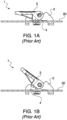
- FIGS 1A and 1B show a prior art cam lock system 1 having a base 2 and a cam lid 3 with teeth 4 that clamp down on a strap 20 that is fed through base 2.
- FIG. 2 once cam lid 3 is raised, there is too much clearance above strap 20, and strap 20 can now slide freely with very little friction.
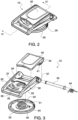
- Cam lid 40 is equipped with teeth 41 on an underside to grip a strap 20 when cam lid 40 is in the lowered position.
- Screw disc 50 has a central protrusion 51 with a rounded top surface that is equipped with ridges 52 or grooves.
- Protrusion 51 has screw threads 53 surrounding protrusion 51 at least on a lower portion thereof. These screw threads 53 mate with screw threads 36 in aperture 35 in base body 30 to attach screw disc 50 to base body 30.
- Rotating screw disc 50 a desired amount causes protrusion 51 to be raised and lowered with respect to base body 30.
- a stop 54 prevents over-turning of screw disc 50 when it is mounted to base body 30.
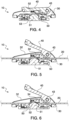
- Strap adjustment system 10 is shown in use in FIGS. 5 and 6 , where here, a strap 20 is placed through base body 30 underneath strap retaining bar 34.
- screw disc 50 is rotated so that protrusion 51 is at a lower point, providing only minor additional friction to keep strap 20 in place, as can be seen by the only minor deformation of the strap 20 as it is pressed toward bar 34.
- screw disc 50 is rotated in such a way that protrusion 51 is raised to a higher level, providing additional friction to strap 20, as can be seen by the greater deformation of strap 20 as it presses against bar 34.
- the user can position protrusion 51 at any desired height to provide the optimal sliding of strap 20 within base body 30.
- FIGS. 7 and 8 show additional embodiments of the strap adjustment system not according to the invention.
- the cam lid is not used, and a strap is tensioned around bars 71, 72 of base body 70.
- Screw disc 50 extends through aperture 74 equipped with screw threads (not shown). Screw disc 50 operates the same way as described above with respect to FIGS. 5 and 6 .
- the base body is in the form of a male buckle portion 80 that is connected to a female buckle portion 90.
- Male buckle portion 80 has a pair of locking legs 81 that extend into a cavity of female buckle portion 90 and snap into locking slots 92 of female buckle portion 90.
- Male buckle portion 80 has a strap retaining bar 84 against which a strap is pressed by protrusion 51 of screw disc 50, which extends through aperture 86 in bottom wall 83 of male portion 80. This aperture 86 is equipped with internal screw threads (not shown). The height of protrusion 51 can be adjusted in the same manner as described above with respect to FIGS. 5 and 6 .
Landscapes
- Buckles (AREA)
- Purses, Travelling Bags, Baskets, Or Suitcases (AREA)
Claims (6)
- Gurtverstellsystem, umfassend:einen Grundkörper (30) mit einer Bodenwand (31), zwei Seitenwänden (32, 33) und einer sich zwischen den zwei Seitenwänden (32, 33) erstreckenden Gurthaltestange (34), wobei die Bodenwand (31) eine durch sie hindurchgehende Öffnung (35) aufweist, wobei die Öffnung (35) Schraubgewindegänge (36) aufweist, die sich um eine Innenfläche davon erstrecken; undeinen Nockendeckel (40), der schwenkbar mit den zwei Seitenwänden (32, 33) verbunden ist, wobei der Nockendeckel (40) eine obere Fläche und eine untere Fläche aufweist, wobei die untere Fläche reibungserzeugende Elemente (41) enthält, die dafür ausgelegt sind, einen durch den Grundkörper (30) geführten Gurt zu ergreifen, wenn der Nockendeckel (40) abgesenkt wird, gekennzeichnet durcheine Schraubscheibe (50) mit einem mittigen Vorsprung (51) und sich um den mittigen Vorsprung (51) erstreckenden Schraubgewindegängen (53), wobei der mittige Vorsprung (51) dafür eingerichtet ist, durch die Öffnung (35) in dem Grundkörper (30) zu passen, indem die Schraubscheibe (50) derart gedreht wird, dass die Gewindegänge (53) in der Schraubscheibe mit den Gewindegängen (36) in der Öffnung ineinandergreifen, sodass eine Höhe des Vorsprungs (51) über der Bodenwand (31) des Grundkörpers durch Drehen der Schraubscheibe (50) einstellbar ist.
- Gurtverstellsystem nach Anspruch 1, wobei der Nockendeckel (40) durch eine Torsionsfeder (44) in einer abgesenkten Position gehalten wird.
- Gurtverstellsystem nach Anspruch 1, wobei die reibungserzeugenden Elemente (41) Zähne sind.
- Gurtverstellsystem nach Anspruch 1, wobei der Nockendeckel (40) über eine Schwenkstange (43), die sich durch Öffnungen in den Seitenwänden und im Nockendeckel erstreckt, mit den Seitenwänden (32, 33) verbunden ist.
- Gurtverstellsystem nach Anspruch 1, wobei der Vorsprung (51) eine abgerundete obere Fläche mit umlaufenden Rippen (52) aufweist, um Reibung gegen einen Gurt zu erzeugen, wenn sich der Gurt durch den Grundkörper (30) erstreckt.
- Gurtverstellsystem nach Anspruch 1, wobei der Grundkörper (30) ferner einen männlichen Schnallenabschnitt (80) mit Verriegelungsbeinen (81) umfasst und ferner einen weiblichen Abschnitt (90) umfasst, wobei die Verriegelungsbeine (81) dafür eingerichtet sind, in Verriegelungsschlitze (92) des weiblichen Abschnitts einzuschnappen.
Applications Claiming Priority (2)
| Application Number | Priority Date | Filing Date | Title |
|---|---|---|---|
| US15/867,861 US10433619B2 (en) | 2018-01-11 | 2018-01-11 | Strap adjustment system |
| PCT/CN2018/110401 WO2019137053A1 (en) | 2018-01-11 | 2018-10-16 | Strap adjustment system |
Publications (3)
| Publication Number | Publication Date |
|---|---|
| EP3737255A1 EP3737255A1 (de) | 2020-11-18 |
| EP3737255A4 EP3737255A4 (de) | 2021-11-10 |
| EP3737255B1 true EP3737255B1 (de) | 2023-07-26 |
Family
ID=67139203
Family Applications (1)
| Application Number | Title | Priority Date | Filing Date |
|---|---|---|---|
| EP18899598.9A Active EP3737255B1 (de) | 2018-01-11 | 2018-10-16 | Gurtverstellsystem |
Country Status (4)
| Country | Link |
|---|---|
| US (1) | US10433619B2 (de) |
| EP (1) | EP3737255B1 (de) |
| CN (1) | CN111565594B (de) |
| WO (1) | WO2019137053A1 (de) |
Families Citing this family (5)
| Publication number | Priority date | Publication date | Assignee | Title |
|---|---|---|---|---|
| US11857032B1 (en) | 2017-08-20 | 2024-01-02 | Team Nexbelt Operating, Inc. | Belt buckle system with threaded retainers |
| US10918169B2 (en) * | 2018-03-02 | 2021-02-16 | Illinois Tool Works Inc. | Locking position adjustment device |
| CN111184600A (zh) * | 2020-03-04 | 2020-05-22 | 张德柳 | 一种产后月子调养理疗仪 |
| AT524761B1 (de) * | 2021-02-15 | 2022-10-15 | Aba Hoertnagl Gmbh | Schnallenbauteil |
| US12156573B2 (en) * | 2022-10-27 | 2024-12-03 | Zipzon, Llc | Fastening system and method(s) |
Family Cites Families (34)
| Publication number | Priority date | Publication date | Assignee | Title |
|---|---|---|---|---|
| US909399A (en) * | 1908-02-10 | 1909-01-12 | Bluford P Greenwood | Letter-tying device. |
| US1037613A (en) * | 1912-03-01 | 1912-09-03 | Benjamin Gizzi | Hitching-strap. |
| US3276085A (en) * | 1962-02-08 | 1966-10-04 | Alfred F Spranger | Safety belt and buckle construction |
| US3741496A (en) * | 1971-07-13 | 1973-06-26 | Allied Chem | Safety seat belt retractor |
| US3794019A (en) * | 1973-01-29 | 1974-02-26 | G Ritland | Finger support |
| US3883928A (en) * | 1974-07-08 | 1975-05-20 | Gerald L Blake | Belt buckle |
| NL7908715A (nl) * | 1979-12-03 | 1981-07-01 | Hennekam Anton Peter | Schroefklemsluiting. |
| US4782425A (en) * | 1985-12-02 | 1988-11-01 | Semtronics Corporation | Conductive elastic strap closure |
| JPH0531925Y2 (de) * | 1986-07-18 | 1993-08-17 | ||
| US4881303A (en) * | 1989-02-17 | 1989-11-21 | Martini M Vey | Quickly adjustable stirrup buckle |
| JPH10117813A (ja) | 1996-10-17 | 1998-05-12 | Miyao Yajima | バンド用バックル |
| GB2329215A (en) * | 1997-09-11 | 1999-03-17 | Kim Ging Hui Enterprise Limite | Adjustable clamp for a drag strap for a dog |
| US5920963A (en) * | 1998-06-17 | 1999-07-13 | Chou; An-Chuan | Rope fastener |
| US5983463A (en) * | 1998-06-17 | 1999-11-16 | Breed Automotive Technology, Inc. | Latchplate or tongue assembly with dual mode of operation |
| US6938925B2 (en) * | 2002-03-14 | 2005-09-06 | Lap Belt Cinch, Inc. | Apparatus for use on a safety belt system for restraining the movement of an occupant or child seat |
| JP3780219B2 (ja) | 2002-03-18 | 2006-05-31 | Ykk株式会社 | バックル |
| US7182370B2 (en) * | 2002-05-13 | 2007-02-27 | Key Safety Systems, Inc. | Height adjuster or adjustable turning loop |
| US7000438B1 (en) * | 2002-05-20 | 2006-02-21 | Restraint Systems Technologies, Inc. | Restraint system and lockable fastener |
| US7185919B2 (en) * | 2003-01-08 | 2007-03-06 | Lap Belt Cinch, Inc. | Method and apparatus for use on a safety belt system for restraining the movement of an occupant or child seat |
| JP4253624B2 (ja) | 2004-08-12 | 2009-04-15 | 株式会社タバタ | 浮力調整器のシリンダバンド |
| US20070193006A1 (en) * | 2006-02-17 | 2007-08-23 | Katsushi Kitano | One-way safety locking buckles |
| US8181319B2 (en) * | 2009-03-30 | 2012-05-22 | D B Industries, Inc. | Buckle |
| WO2012106374A1 (en) * | 2011-02-01 | 2012-08-09 | Bio Cybernetics International, Inc. | Secure adjustable orthotic device |
| US8938862B2 (en) * | 2011-04-26 | 2015-01-27 | Andre' Grasso | Tie-down strap with braking system and method |
| JP6336907B2 (ja) | 2012-09-07 | 2018-06-06 | Ykk株式会社 | ベルトアジャスター |
| US8522402B1 (en) * | 2012-12-11 | 2013-09-03 | James D. Spooler | Cargo strap collector |
| GB2515293B (en) * | 2013-06-18 | 2015-06-03 | Hcl Fasteners Ltd | Fastener |
| US9622532B2 (en) * | 2013-08-02 | 2017-04-18 | Riddell, Inc. | Sports helmet with adjustable chin strap system |
| US9155359B1 (en) | 2013-09-16 | 2015-10-13 | Dennis Morgan Bailey | Ratchet buckle with locking mechanism |
| CN203828198U (zh) | 2014-03-13 | 2014-09-17 | 裘里斯杨 | 带扣以及长度可调的带状物 |
| US9827480B2 (en) * | 2014-03-14 | 2017-11-28 | Home Team Sports, Llc | Strap latching device |
| US9307807B2 (en) * | 2014-06-19 | 2016-04-12 | Wen-Sheng Huang | Tie locking device |
| CN204070955U (zh) | 2014-09-24 | 2015-01-07 | 胡金花 | 一种锁扣 |
| ES1131955Y (es) * | 2014-10-23 | 2015-01-28 | Bresco Arturo Puig | Dispositivo de desplazamiento guiado para puntos de fijacion de los medios de inmovilizacion de personas |
-
2018
- 2018-01-11 US US15/867,861 patent/US10433619B2/en active Active
- 2018-10-16 EP EP18899598.9A patent/EP3737255B1/de active Active
- 2018-10-16 CN CN201880085567.XA patent/CN111565594B/zh active Active
- 2018-10-16 WO PCT/CN2018/110401 patent/WO2019137053A1/en not_active Ceased
Also Published As
| Publication number | Publication date |
|---|---|
| EP3737255A4 (de) | 2021-11-10 |
| US10433619B2 (en) | 2019-10-08 |
| US20190208868A1 (en) | 2019-07-11 |
| EP3737255A1 (de) | 2020-11-18 |
| CN111565594B (zh) | 2023-06-30 |
| WO2019137053A1 (en) | 2019-07-18 |
| CN111565594A (zh) | 2020-08-21 |
Similar Documents
| Publication | Publication Date | Title |
|---|---|---|
| EP3737255B1 (de) | Gurtverstellsystem | |
| US9664479B1 (en) | Adjustable firearm stock | |
| US9664476B1 (en) | Adjustable firearm stock | |
| US7478735B2 (en) | Secure removable gripping device | |
| US5774947A (en) | Anti-slip webbing adjuster | |
| US5357939A (en) | Bow string release with continuous loop wrist strap and reversible trigger mechanism | |
| US4438669A (en) | Adjustable ratchet pliers | |
| US6227080B1 (en) | Vice-grip pliers | |
| US20080157450A1 (en) | Auto-advance bar clamp | |
| US7866321B2 (en) | Reusable restraining apparatus with double lock | |
| US7007909B2 (en) | Locking device for a telescopic tube assembly | |
| US20020154943A1 (en) | Quick release clasping device for rake or other tools | |
| US4901609A (en) | Adjustable pliers | |
| US20100282032A1 (en) | Self-adjusting pliers | |
| US10066659B2 (en) | Hook | |
| US6408725B1 (en) | Pliers | |
| US20210045499A1 (en) | Compact Ratcheting Buckle Mechanism | |
| US20040107804A1 (en) | Open end wrench | |
| US10219441B2 (en) | Multi-position lock for pruning device | |
| US12364322B2 (en) | Adjustable mount for a backpack or schoolbag | |
| DE4240926A1 (de) | ||
| EP3238558A1 (de) | Schnalle für helm | |
| US6848342B2 (en) | Adjustable self-locking wrench | |
| CN114556042B (zh) | 手枪枪套 | |
| US20040033117A1 (en) | Cargo bar |
Legal Events
| Date | Code | Title | Description |
|---|---|---|---|
| STAA | Information on the status of an ep patent application or granted ep patent |
Free format text: STATUS: THE INTERNATIONAL PUBLICATION HAS BEEN MADE |
|
| PUAI | Public reference made under article 153(3) epc to a published international application that has entered the european phase |
Free format text: ORIGINAL CODE: 0009012 |
|
| STAA | Information on the status of an ep patent application or granted ep patent |
Free format text: STATUS: REQUEST FOR EXAMINATION WAS MADE |
|
| 17P | Request for examination filed |
Effective date: 20200630 |
|
| AK | Designated contracting states |
Kind code of ref document: A1 Designated state(s): AL AT BE BG CH CY CZ DE DK EE ES FI FR GB GR HR HU IE IS IT LI LT LU LV MC MK MT NL NO PL PT RO RS SE SI SK SM TR |
|
| AX | Request for extension of the european patent |
Extension state: BA ME |
|
| DAV | Request for validation of the european patent (deleted) | ||
| DAX | Request for extension of the european patent (deleted) | ||
| A4 | Supplementary search report drawn up and despatched |
Effective date: 20211011 |
|
| RIC1 | Information provided on ipc code assigned before grant |
Ipc: A44B 11/12 20060101ALI20211005BHEP Ipc: A44B 11/06 20060101AFI20211005BHEP |
|
| GRAP | Despatch of communication of intention to grant a patent |
Free format text: ORIGINAL CODE: EPIDOSNIGR1 |
|
| STAA | Information on the status of an ep patent application or granted ep patent |
Free format text: STATUS: GRANT OF PATENT IS INTENDED |
|
| INTG | Intention to grant announced |
Effective date: 20230411 |
|
| GRAS | Grant fee paid |
Free format text: ORIGINAL CODE: EPIDOSNIGR3 |
|
| GRAA | (expected) grant |
Free format text: ORIGINAL CODE: 0009210 |
|
| STAA | Information on the status of an ep patent application or granted ep patent |
Free format text: STATUS: THE PATENT HAS BEEN GRANTED |
|
| AK | Designated contracting states |
Kind code of ref document: B1 Designated state(s): AL AT BE BG CH CY CZ DE DK EE ES FI FR GB GR HR HU IE IS IT LI LT LU LV MC MK MT NL NO PL PT RO RS SE SI SK SM TR |
|
| REG | Reference to a national code |
Ref country code: CH Ref legal event code: EP |
|
| REG | Reference to a national code |
Ref country code: DE Ref legal event code: R096 Ref document number: 602018054310 Country of ref document: DE |
|
| REG | Reference to a national code |
Ref country code: IE Ref legal event code: FG4D |
|
| P01 | Opt-out of the competence of the unified patent court (upc) registered |
Effective date: 20230910 |
|
| REG | Reference to a national code |
Ref country code: LT Ref legal event code: MG9D |
|
| REG | Reference to a national code |
Ref country code: NL Ref legal event code: MP Effective date: 20230726 |
|
| REG | Reference to a national code |
Ref country code: AT Ref legal event code: MK05 Ref document number: 1590880 Country of ref document: AT Kind code of ref document: T Effective date: 20230726 |
|
| PG25 | Lapsed in a contracting state [announced via postgrant information from national office to epo] |
Ref country code: NL Free format text: LAPSE BECAUSE OF FAILURE TO SUBMIT A TRANSLATION OF THE DESCRIPTION OR TO PAY THE FEE WITHIN THE PRESCRIBED TIME-LIMIT Effective date: 20230726 |
|
| PG25 | Lapsed in a contracting state [announced via postgrant information from national office to epo] |
Ref country code: GR Free format text: LAPSE BECAUSE OF FAILURE TO SUBMIT A TRANSLATION OF THE DESCRIPTION OR TO PAY THE FEE WITHIN THE PRESCRIBED TIME-LIMIT Effective date: 20231027 |
|
| PG25 | Lapsed in a contracting state [announced via postgrant information from national office to epo] |
Ref country code: IS Free format text: LAPSE BECAUSE OF FAILURE TO SUBMIT A TRANSLATION OF THE DESCRIPTION OR TO PAY THE FEE WITHIN THE PRESCRIBED TIME-LIMIT Effective date: 20231126 |
|
| PG25 | Lapsed in a contracting state [announced via postgrant information from national office to epo] |
Ref country code: SE Free format text: LAPSE BECAUSE OF FAILURE TO SUBMIT A TRANSLATION OF THE DESCRIPTION OR TO PAY THE FEE WITHIN THE PRESCRIBED TIME-LIMIT Effective date: 20230726 Ref country code: RS Free format text: LAPSE BECAUSE OF FAILURE TO SUBMIT A TRANSLATION OF THE DESCRIPTION OR TO PAY THE FEE WITHIN THE PRESCRIBED TIME-LIMIT Effective date: 20230726 Ref country code: PT Free format text: LAPSE BECAUSE OF FAILURE TO SUBMIT A TRANSLATION OF THE DESCRIPTION OR TO PAY THE FEE WITHIN THE PRESCRIBED TIME-LIMIT Effective date: 20231127 Ref country code: NO Free format text: LAPSE BECAUSE OF FAILURE TO SUBMIT A TRANSLATION OF THE DESCRIPTION OR TO PAY THE FEE WITHIN THE PRESCRIBED TIME-LIMIT Effective date: 20231026 Ref country code: LV Free format text: LAPSE BECAUSE OF FAILURE TO SUBMIT A TRANSLATION OF THE DESCRIPTION OR TO PAY THE FEE WITHIN THE PRESCRIBED TIME-LIMIT Effective date: 20230726 Ref country code: LT Free format text: LAPSE BECAUSE OF FAILURE TO SUBMIT A TRANSLATION OF THE DESCRIPTION OR TO PAY THE FEE WITHIN THE PRESCRIBED TIME-LIMIT Effective date: 20230726 Ref country code: IS Free format text: LAPSE BECAUSE OF FAILURE TO SUBMIT A TRANSLATION OF THE DESCRIPTION OR TO PAY THE FEE WITHIN THE PRESCRIBED TIME-LIMIT Effective date: 20231126 Ref country code: HR Free format text: LAPSE BECAUSE OF FAILURE TO SUBMIT A TRANSLATION OF THE DESCRIPTION OR TO PAY THE FEE WITHIN THE PRESCRIBED TIME-LIMIT Effective date: 20230726 Ref country code: GR Free format text: LAPSE BECAUSE OF FAILURE TO SUBMIT A TRANSLATION OF THE DESCRIPTION OR TO PAY THE FEE WITHIN THE PRESCRIBED TIME-LIMIT Effective date: 20231027 Ref country code: FI Free format text: LAPSE BECAUSE OF FAILURE TO SUBMIT A TRANSLATION OF THE DESCRIPTION OR TO PAY THE FEE WITHIN THE PRESCRIBED TIME-LIMIT Effective date: 20230726 Ref country code: AT Free format text: LAPSE BECAUSE OF FAILURE TO SUBMIT A TRANSLATION OF THE DESCRIPTION OR TO PAY THE FEE WITHIN THE PRESCRIBED TIME-LIMIT Effective date: 20230726 |
|
| PG25 | Lapsed in a contracting state [announced via postgrant information from national office to epo] |
Ref country code: PL Free format text: LAPSE BECAUSE OF FAILURE TO SUBMIT A TRANSLATION OF THE DESCRIPTION OR TO PAY THE FEE WITHIN THE PRESCRIBED TIME-LIMIT Effective date: 20230726 |
|
| PG25 | Lapsed in a contracting state [announced via postgrant information from national office to epo] |
Ref country code: ES Free format text: LAPSE BECAUSE OF FAILURE TO SUBMIT A TRANSLATION OF THE DESCRIPTION OR TO PAY THE FEE WITHIN THE PRESCRIBED TIME-LIMIT Effective date: 20230726 |
|
| REG | Reference to a national code |
Ref country code: DE Ref legal event code: R097 Ref document number: 602018054310 Country of ref document: DE |
|
| PG25 | Lapsed in a contracting state [announced via postgrant information from national office to epo] |
Ref country code: SM Free format text: LAPSE BECAUSE OF FAILURE TO SUBMIT A TRANSLATION OF THE DESCRIPTION OR TO PAY THE FEE WITHIN THE PRESCRIBED TIME-LIMIT Effective date: 20230726 Ref country code: RO Free format text: LAPSE BECAUSE OF FAILURE TO SUBMIT A TRANSLATION OF THE DESCRIPTION OR TO PAY THE FEE WITHIN THE PRESCRIBED TIME-LIMIT Effective date: 20230726 Ref country code: ES Free format text: LAPSE BECAUSE OF FAILURE TO SUBMIT A TRANSLATION OF THE DESCRIPTION OR TO PAY THE FEE WITHIN THE PRESCRIBED TIME-LIMIT Effective date: 20230726 Ref country code: EE Free format text: LAPSE BECAUSE OF FAILURE TO SUBMIT A TRANSLATION OF THE DESCRIPTION OR TO PAY THE FEE WITHIN THE PRESCRIBED TIME-LIMIT Effective date: 20230726 Ref country code: DK Free format text: LAPSE BECAUSE OF FAILURE TO SUBMIT A TRANSLATION OF THE DESCRIPTION OR TO PAY THE FEE WITHIN THE PRESCRIBED TIME-LIMIT Effective date: 20230726 Ref country code: CZ Free format text: LAPSE BECAUSE OF FAILURE TO SUBMIT A TRANSLATION OF THE DESCRIPTION OR TO PAY THE FEE WITHIN THE PRESCRIBED TIME-LIMIT Effective date: 20230726 Ref country code: SK Free format text: LAPSE BECAUSE OF FAILURE TO SUBMIT A TRANSLATION OF THE DESCRIPTION OR TO PAY THE FEE WITHIN THE PRESCRIBED TIME-LIMIT Effective date: 20230726 |
|
| PG25 | Lapsed in a contracting state [announced via postgrant information from national office to epo] |
Ref country code: IT Free format text: LAPSE BECAUSE OF FAILURE TO SUBMIT A TRANSLATION OF THE DESCRIPTION OR TO PAY THE FEE WITHIN THE PRESCRIBED TIME-LIMIT Effective date: 20230726 Ref country code: MC Free format text: LAPSE BECAUSE OF FAILURE TO SUBMIT A TRANSLATION OF THE DESCRIPTION OR TO PAY THE FEE WITHIN THE PRESCRIBED TIME-LIMIT Effective date: 20230726 |
|
| PLBE | No opposition filed within time limit |
Free format text: ORIGINAL CODE: 0009261 |
|
| REG | Reference to a national code |
Ref country code: CH Ref legal event code: PL |
|
| STAA | Information on the status of an ep patent application or granted ep patent |
Free format text: STATUS: NO OPPOSITION FILED WITHIN TIME LIMIT |
|
| REG | Reference to a national code |
Ref country code: BE Ref legal event code: MM Effective date: 20231031 |
|
| PG25 | Lapsed in a contracting state [announced via postgrant information from national office to epo] |
Ref country code: LU Free format text: LAPSE BECAUSE OF NON-PAYMENT OF DUE FEES Effective date: 20231016 |
|
| GBPC | Gb: european patent ceased through non-payment of renewal fee |
Effective date: 20231026 |
|
| PG25 | Lapsed in a contracting state [announced via postgrant information from national office to epo] |
Ref country code: LU Free format text: LAPSE BECAUSE OF NON-PAYMENT OF DUE FEES Effective date: 20231016 |
|
| 26N | No opposition filed |
Effective date: 20240429 |
|
| PG25 | Lapsed in a contracting state [announced via postgrant information from national office to epo] |
Ref country code: GB Free format text: LAPSE BECAUSE OF NON-PAYMENT OF DUE FEES Effective date: 20231026 |
|
| PG25 | Lapsed in a contracting state [announced via postgrant information from national office to epo] |
Ref country code: CH Free format text: LAPSE BECAUSE OF NON-PAYMENT OF DUE FEES Effective date: 20231031 |
|
| PG25 | Lapsed in a contracting state [announced via postgrant information from national office to epo] |
Ref country code: SI Free format text: LAPSE BECAUSE OF FAILURE TO SUBMIT A TRANSLATION OF THE DESCRIPTION OR TO PAY THE FEE WITHIN THE PRESCRIBED TIME-LIMIT Effective date: 20230726 Ref country code: GB Free format text: LAPSE BECAUSE OF NON-PAYMENT OF DUE FEES Effective date: 20231026 Ref country code: CH Free format text: LAPSE BECAUSE OF NON-PAYMENT OF DUE FEES Effective date: 20231031 |
|
| PG25 | Lapsed in a contracting state [announced via postgrant information from national office to epo] |
Ref country code: BE Free format text: LAPSE BECAUSE OF NON-PAYMENT OF DUE FEES Effective date: 20231031 |
|
| PG25 | Lapsed in a contracting state [announced via postgrant information from national office to epo] |
Ref country code: IE Free format text: LAPSE BECAUSE OF NON-PAYMENT OF DUE FEES Effective date: 20231016 |
|
| PG25 | Lapsed in a contracting state [announced via postgrant information from national office to epo] |
Ref country code: IE Free format text: LAPSE BECAUSE OF NON-PAYMENT OF DUE FEES Effective date: 20231016 |
|
| PG25 | Lapsed in a contracting state [announced via postgrant information from national office to epo] |
Ref country code: BG Free format text: LAPSE BECAUSE OF FAILURE TO SUBMIT A TRANSLATION OF THE DESCRIPTION OR TO PAY THE FEE WITHIN THE PRESCRIBED TIME-LIMIT Effective date: 20230726 |
|
| PG25 | Lapsed in a contracting state [announced via postgrant information from national office to epo] |
Ref country code: BG Free format text: LAPSE BECAUSE OF FAILURE TO SUBMIT A TRANSLATION OF THE DESCRIPTION OR TO PAY THE FEE WITHIN THE PRESCRIBED TIME-LIMIT Effective date: 20230726 |
|
| PG25 | Lapsed in a contracting state [announced via postgrant information from national office to epo] |
Ref country code: CY Free format text: LAPSE BECAUSE OF FAILURE TO SUBMIT A TRANSLATION OF THE DESCRIPTION OR TO PAY THE FEE WITHIN THE PRESCRIBED TIME-LIMIT; INVALID AB INITIO Effective date: 20181016 |
|
| PG25 | Lapsed in a contracting state [announced via postgrant information from national office to epo] |
Ref country code: HU Free format text: LAPSE BECAUSE OF FAILURE TO SUBMIT A TRANSLATION OF THE DESCRIPTION OR TO PAY THE FEE WITHIN THE PRESCRIBED TIME-LIMIT; INVALID AB INITIO Effective date: 20181016 |
|
| PG25 | Lapsed in a contracting state [announced via postgrant information from national office to epo] |
Ref country code: TR Free format text: LAPSE BECAUSE OF FAILURE TO SUBMIT A TRANSLATION OF THE DESCRIPTION OR TO PAY THE FEE WITHIN THE PRESCRIBED TIME-LIMIT Effective date: 20230726 |
|
| PGFP | Annual fee paid to national office [announced via postgrant information from national office to epo] |
Ref country code: DE Payment date: 20251010 Year of fee payment: 8 |
|
| PGFP | Annual fee paid to national office [announced via postgrant information from national office to epo] |
Ref country code: FR Payment date: 20251014 Year of fee payment: 8 |