EP3736852A1 - Alignement d'une structure de support de composants avec des sections réputées bonnes et d'une section critique avec un autre support de composants comportant des composants et des dispositifs factices - Google Patents
Alignement d'une structure de support de composants avec des sections réputées bonnes et d'une section critique avec un autre support de composants comportant des composants et des dispositifs factices Download PDFInfo
- Publication number
- EP3736852A1 EP3736852A1 EP19173014.2A EP19173014A EP3736852A1 EP 3736852 A1 EP3736852 A1 EP 3736852A1 EP 19173014 A EP19173014 A EP 19173014A EP 3736852 A1 EP3736852 A1 EP 3736852A1
- Authority
- EP
- European Patent Office
- Prior art keywords
- component carrier
- component
- section
- carrier structure
- functional
- Prior art date
- Legal status (The legal status is an assumption and is not a legal conclusion. Google has not performed a legal analysis and makes no representation as to the accuracy of the status listed.)
- Pending
Links
- 238000000034 method Methods 0.000 claims abstract description 68
- 238000012360 testing method Methods 0.000 claims abstract description 65
- 238000004519 manufacturing process Methods 0.000 claims abstract description 55
- 239000000969 carrier Substances 0.000 claims abstract description 54
- 238000003475 lamination Methods 0.000 claims description 31
- 239000000463 material Substances 0.000 claims description 30
- 229920005989 resin Polymers 0.000 claims description 25
- 239000011347 resin Substances 0.000 claims description 25
- 239000011265 semifinished product Substances 0.000 claims description 25
- RYGMFSIKBFXOCR-UHFFFAOYSA-N Copper Chemical compound [Cu] RYGMFSIKBFXOCR-UHFFFAOYSA-N 0.000 claims description 24
- 238000007639 printing Methods 0.000 claims description 23
- 229910052802 copper Inorganic materials 0.000 claims description 21
- 239000010949 copper Substances 0.000 claims description 21
- 239000000758 substrate Substances 0.000 claims description 16
- 230000003014 reinforcing effect Effects 0.000 claims description 13
- 239000000654 additive Substances 0.000 claims description 10
- 230000000996 additive effect Effects 0.000 claims description 10
- 239000004020 conductor Substances 0.000 claims description 10
- 238000010030 laminating Methods 0.000 claims description 10
- 239000002699 waste material Substances 0.000 claims description 10
- 239000002245 particle Substances 0.000 claims description 9
- 239000011521 glass Substances 0.000 claims description 8
- 239000004593 Epoxy Substances 0.000 claims description 7
- 238000012545 processing Methods 0.000 claims description 7
- 239000003822 epoxy resin Substances 0.000 claims description 6
- 229920000647 polyepoxide Polymers 0.000 claims description 6
- -1 polyphenylene Polymers 0.000 claims description 5
- 238000007650 screen-printing Methods 0.000 claims description 5
- 229920000106 Liquid crystal polymer Polymers 0.000 claims description 4
- 239000004977 Liquid-crystal polymers (LCPs) Substances 0.000 claims description 4
- PXHVJJICTQNCMI-UHFFFAOYSA-N Nickel Chemical compound [Ni] PXHVJJICTQNCMI-UHFFFAOYSA-N 0.000 claims description 4
- KDLHZDBZIXYQEI-UHFFFAOYSA-N Palladium Chemical compound [Pd] KDLHZDBZIXYQEI-UHFFFAOYSA-N 0.000 claims description 4
- 238000004590 computer program Methods 0.000 claims description 4
- 230000005291 magnetic effect Effects 0.000 claims description 4
- 239000004642 Polyimide Substances 0.000 claims description 3
- 229910052782 aluminium Inorganic materials 0.000 claims description 3
- XAGFODPZIPBFFR-UHFFFAOYSA-N aluminium Chemical compound [Al] XAGFODPZIPBFFR-UHFFFAOYSA-N 0.000 claims description 3
- 239000000919 ceramic Substances 0.000 claims description 3
- 239000004643 cyanate ester Substances 0.000 claims description 3
- 229920001721 polyimide Polymers 0.000 claims description 3
- 229920001343 polytetrafluoroethylene Polymers 0.000 claims description 3
- 239000012783 reinforcing fiber Substances 0.000 claims description 3
- 238000003860 storage Methods 0.000 claims description 3
- OKTJSMMVPCPJKN-UHFFFAOYSA-N Carbon Chemical compound [C] OKTJSMMVPCPJKN-UHFFFAOYSA-N 0.000 claims description 2
- 239000004952 Polyamide Substances 0.000 claims description 2
- 229920000265 Polyparaphenylene Polymers 0.000 claims description 2
- BQCADISMDOOEFD-UHFFFAOYSA-N Silver Chemical compound [Ag] BQCADISMDOOEFD-UHFFFAOYSA-N 0.000 claims description 2
- 239000003990 capacitor Substances 0.000 claims description 2
- PCHJSUWPFVWCPO-UHFFFAOYSA-N gold Chemical compound [Au] PCHJSUWPFVWCPO-UHFFFAOYSA-N 0.000 claims description 2
- 229910052737 gold Inorganic materials 0.000 claims description 2
- 239000010931 gold Substances 0.000 claims description 2
- 229910021389 graphene Inorganic materials 0.000 claims description 2
- 238000003306 harvesting Methods 0.000 claims description 2
- 238000007641 inkjet printing Methods 0.000 claims description 2
- 229910044991 metal oxide Inorganic materials 0.000 claims description 2
- 150000004706 metal oxides Chemical class 0.000 claims description 2
- 229910052759 nickel Inorganic materials 0.000 claims description 2
- 230000005693 optoelectronics Effects 0.000 claims description 2
- 229910052763 palladium Inorganic materials 0.000 claims description 2
- 229920002647 polyamide Polymers 0.000 claims description 2
- 239000004810 polytetrafluoroethylene Substances 0.000 claims description 2
- 229910052709 silver Inorganic materials 0.000 claims description 2
- 239000004332 silver Substances 0.000 claims description 2
- 238000012546 transfer Methods 0.000 claims description 2
- WFKWXMTUELFFGS-UHFFFAOYSA-N tungsten Chemical compound [W] WFKWXMTUELFFGS-UHFFFAOYSA-N 0.000 claims description 2
- 229910052721 tungsten Inorganic materials 0.000 claims description 2
- 239000010937 tungsten Substances 0.000 claims description 2
- 239000000306 component Substances 0.000 description 509
- 239000010410 layer Substances 0.000 description 116
- 230000006870 function Effects 0.000 description 17
- 238000011990 functional testing Methods 0.000 description 8
- 238000000059 patterning Methods 0.000 description 8
- 239000003365 glass fiber Substances 0.000 description 7
- 238000013461 design Methods 0.000 description 6
- 230000008901 benefit Effects 0.000 description 5
- 230000015572 biosynthetic process Effects 0.000 description 5
- 238000005553 drilling Methods 0.000 description 4
- 230000006798 recombination Effects 0.000 description 4
- 238000005215 recombination Methods 0.000 description 4
- 239000004065 semiconductor Substances 0.000 description 4
- 238000013459 approach Methods 0.000 description 3
- 239000012876 carrier material Substances 0.000 description 3
- 150000001875 compounds Chemical class 0.000 description 3
- 230000008878 coupling Effects 0.000 description 3
- 238000010168 coupling process Methods 0.000 description 3
- 238000005859 coupling reaction Methods 0.000 description 3
- 238000005516 engineering process Methods 0.000 description 3
- 229910052751 metal Inorganic materials 0.000 description 3
- 239000002184 metal Substances 0.000 description 3
- 229920000642 polymer Polymers 0.000 description 3
- 238000003825 pressing Methods 0.000 description 3
- 230000008569 process Effects 0.000 description 3
- XUIMIQQOPSSXEZ-UHFFFAOYSA-N Silicon Chemical compound [Si] XUIMIQQOPSSXEZ-UHFFFAOYSA-N 0.000 description 2
- 239000000443 aerosol Substances 0.000 description 2
- QXJJQWWVWRCVQT-UHFFFAOYSA-K calcium;sodium;phosphate Chemical compound [Na+].[Ca+2].[O-]P([O-])([O-])=O QXJJQWWVWRCVQT-UHFFFAOYSA-K 0.000 description 2
- 238000003486 chemical etching Methods 0.000 description 2
- 239000000470 constituent Substances 0.000 description 2
- 239000011889 copper foil Substances 0.000 description 2
- 238000004132 cross linking Methods 0.000 description 2
- 230000003247 decreasing effect Effects 0.000 description 2
- 230000007547 defect Effects 0.000 description 2
- 230000005670 electromagnetic radiation Effects 0.000 description 2
- 239000011888 foil Substances 0.000 description 2
- 238000007689 inspection Methods 0.000 description 2
- 230000010354 integration Effects 0.000 description 2
- 230000003287 optical effect Effects 0.000 description 2
- 239000000047 product Substances 0.000 description 2
- 238000012797 qualification Methods 0.000 description 2
- 230000004044 response Effects 0.000 description 2
- 238000000926 separation method Methods 0.000 description 2
- 239000010703 silicon Substances 0.000 description 2
- 229910052710 silicon Inorganic materials 0.000 description 2
- 239000002904 solvent Substances 0.000 description 2
- 239000000853 adhesive Substances 0.000 description 1
- 230000001070 adhesive effect Effects 0.000 description 1
- 230000005290 antiferromagnetic effect Effects 0.000 description 1
- 238000003491 array Methods 0.000 description 1
- UMIVXZPTRXBADB-UHFFFAOYSA-N benzocyclobutene Chemical compound C1=CC=C2CCC2=C1 UMIVXZPTRXBADB-UHFFFAOYSA-N 0.000 description 1
- 230000015556 catabolic process Effects 0.000 description 1
- 238000004891 communication Methods 0.000 description 1
- 238000010276 construction Methods 0.000 description 1
- 238000001816 cooling Methods 0.000 description 1
- 239000008358 core component Substances 0.000 description 1
- 238000005520 cutting process Methods 0.000 description 1
- 238000012517 data analytics Methods 0.000 description 1
- 238000006731 degradation reaction Methods 0.000 description 1
- 238000009826 distribution Methods 0.000 description 1
- 238000001312 dry etching Methods 0.000 description 1
- 239000012777 electrically insulating material Substances 0.000 description 1
- 238000002813 epsilometer test Methods 0.000 description 1
- 238000005530 etching Methods 0.000 description 1
- 230000005293 ferrimagnetic effect Effects 0.000 description 1
- 230000005294 ferromagnetic effect Effects 0.000 description 1
- 239000000835 fiber Substances 0.000 description 1
- 238000003384 imaging method Methods 0.000 description 1
- 230000001976 improved effect Effects 0.000 description 1
- 230000006872 improvement Effects 0.000 description 1
- 238000002347 injection Methods 0.000 description 1
- 239000007924 injection Substances 0.000 description 1
- 238000003698 laser cutting Methods 0.000 description 1
- 239000007788 liquid Substances 0.000 description 1
- 238000001459 lithography Methods 0.000 description 1
- 238000005259 measurement Methods 0.000 description 1
- 230000005226 mechanical processes and functions Effects 0.000 description 1
- 238000005457 optimization Methods 0.000 description 1
- 239000011368 organic material Substances 0.000 description 1
- 230000005298 paramagnetic effect Effects 0.000 description 1
- 239000004033 plastic Substances 0.000 description 1
- 229920003023 plastic Polymers 0.000 description 1
- 229920002577 polybenzoxazole Polymers 0.000 description 1
- 238000012805 post-processing Methods 0.000 description 1
- 230000001737 promoting effect Effects 0.000 description 1
- 230000001902 propagating effect Effects 0.000 description 1
- 238000004064 recycling Methods 0.000 description 1
- 239000012779 reinforcing material Substances 0.000 description 1
- 230000008439 repair process Effects 0.000 description 1
- 230000000630 rising effect Effects 0.000 description 1
- 239000002356 single layer Substances 0.000 description 1
- 238000005245 sintering Methods 0.000 description 1
- 238000005476 soldering Methods 0.000 description 1
- 239000007787 solid Substances 0.000 description 1
- 239000000243 solution Substances 0.000 description 1
- 230000003746 surface roughness Effects 0.000 description 1
- 238000011179 visual inspection Methods 0.000 description 1
- 229910000859 α-Fe Inorganic materials 0.000 description 1
Images

Classifications
-
- H—ELECTRICITY
- H01—ELECTRIC ELEMENTS
- H01L—SEMICONDUCTOR DEVICES NOT COVERED BY CLASS H10
- H01L22/00—Testing or measuring during manufacture or treatment; Reliability measurements, i.e. testing of parts without further processing to modify the parts as such; Structural arrangements therefor
- H01L22/20—Sequence of activities consisting of a plurality of measurements, corrections, marking or sorting steps
-
- H—ELECTRICITY
- H05—ELECTRIC TECHNIQUES NOT OTHERWISE PROVIDED FOR
- H05K—PRINTED CIRCUITS; CASINGS OR CONSTRUCTIONAL DETAILS OF ELECTRIC APPARATUS; MANUFACTURE OF ASSEMBLAGES OF ELECTRICAL COMPONENTS
- H05K3/00—Apparatus or processes for manufacturing printed circuits
- H05K3/30—Assembling printed circuits with electric components, e.g. with resistor
-
- H—ELECTRICITY
- H01—ELECTRIC ELEMENTS
- H01L—SEMICONDUCTOR DEVICES NOT COVERED BY CLASS H10
- H01L21/00—Processes or apparatus adapted for the manufacture or treatment of semiconductor or solid state devices or of parts thereof
- H01L21/02—Manufacture or treatment of semiconductor devices or of parts thereof
- H01L21/04—Manufacture or treatment of semiconductor devices or of parts thereof the devices having potential barriers, e.g. a PN junction, depletion layer or carrier concentration layer
- H01L21/48—Manufacture or treatment of parts, e.g. containers, prior to assembly of the devices, using processes not provided for in a single one of the subgroups H01L21/06 - H01L21/326
- H01L21/4814—Conductive parts
- H01L21/4846—Leads on or in insulating or insulated substrates, e.g. metallisation
- H01L21/4857—Multilayer substrates
-
- H—ELECTRICITY
- H01—ELECTRIC ELEMENTS
- H01L—SEMICONDUCTOR DEVICES NOT COVERED BY CLASS H10
- H01L21/00—Processes or apparatus adapted for the manufacture or treatment of semiconductor or solid state devices or of parts thereof
- H01L21/02—Manufacture or treatment of semiconductor devices or of parts thereof
- H01L21/04—Manufacture or treatment of semiconductor devices or of parts thereof the devices having potential barriers, e.g. a PN junction, depletion layer or carrier concentration layer
- H01L21/48—Manufacture or treatment of parts, e.g. containers, prior to assembly of the devices, using processes not provided for in a single one of the subgroups H01L21/06 - H01L21/326
- H01L21/4814—Conductive parts
- H01L21/4846—Leads on or in insulating or insulated substrates, e.g. metallisation
- H01L21/4867—Applying pastes or inks, e.g. screen printing
-
- H—ELECTRICITY
- H01—ELECTRIC ELEMENTS
- H01L—SEMICONDUCTOR DEVICES NOT COVERED BY CLASS H10
- H01L22/00—Testing or measuring during manufacture or treatment; Reliability measurements, i.e. testing of parts without further processing to modify the parts as such; Structural arrangements therefor
- H01L22/10—Measuring as part of the manufacturing process
- H01L22/14—Measuring as part of the manufacturing process for electrical parameters, e.g. resistance, deep-levels, CV, diffusions by electrical means
-
- H—ELECTRICITY
- H01—ELECTRIC ELEMENTS
- H01L—SEMICONDUCTOR DEVICES NOT COVERED BY CLASS H10
- H01L23/00—Details of semiconductor or other solid state devices
- H01L23/28—Encapsulations, e.g. encapsulating layers, coatings, e.g. for protection
- H01L23/31—Encapsulations, e.g. encapsulating layers, coatings, e.g. for protection characterised by the arrangement or shape
- H01L23/3107—Encapsulations, e.g. encapsulating layers, coatings, e.g. for protection characterised by the arrangement or shape the device being completely enclosed
- H01L23/3121—Encapsulations, e.g. encapsulating layers, coatings, e.g. for protection characterised by the arrangement or shape the device being completely enclosed a substrate forming part of the encapsulation
-
- H—ELECTRICITY
- H01—ELECTRIC ELEMENTS
- H01L—SEMICONDUCTOR DEVICES NOT COVERED BY CLASS H10
- H01L23/00—Details of semiconductor or other solid state devices
- H01L23/48—Arrangements for conducting electric current to or from the solid state body in operation, e.g. leads, terminal arrangements ; Selection of materials therefor
- H01L23/488—Arrangements for conducting electric current to or from the solid state body in operation, e.g. leads, terminal arrangements ; Selection of materials therefor consisting of soldered or bonded constructions
- H01L23/498—Leads, i.e. metallisations or lead-frames on insulating substrates, e.g. chip carriers
- H01L23/49822—Multilayer substrates
-
- H—ELECTRICITY
- H01—ELECTRIC ELEMENTS
- H01L—SEMICONDUCTOR DEVICES NOT COVERED BY CLASS H10
- H01L24/00—Arrangements for connecting or disconnecting semiconductor or solid-state bodies; Methods or apparatus related thereto
- H01L24/01—Means for bonding being attached to, or being formed on, the surface to be connected, e.g. chip-to-package, die-attach, "first-level" interconnects; Manufacturing methods related thereto
- H01L24/18—High density interconnect [HDI] connectors; Manufacturing methods related thereto
- H01L24/19—Manufacturing methods of high density interconnect preforms
-
- H—ELECTRICITY
- H01—ELECTRIC ELEMENTS
- H01L—SEMICONDUCTOR DEVICES NOT COVERED BY CLASS H10
- H01L24/00—Arrangements for connecting or disconnecting semiconductor or solid-state bodies; Methods or apparatus related thereto
- H01L24/01—Means for bonding being attached to, or being formed on, the surface to be connected, e.g. chip-to-package, die-attach, "first-level" interconnects; Manufacturing methods related thereto
- H01L24/18—High density interconnect [HDI] connectors; Manufacturing methods related thereto
- H01L24/23—Structure, shape, material or disposition of the high density interconnect connectors after the connecting process
- H01L24/24—Structure, shape, material or disposition of the high density interconnect connectors after the connecting process of an individual high density interconnect connector
-
- H—ELECTRICITY
- H01—ELECTRIC ELEMENTS
- H01L—SEMICONDUCTOR DEVICES NOT COVERED BY CLASS H10
- H01L24/00—Arrangements for connecting or disconnecting semiconductor or solid-state bodies; Methods or apparatus related thereto
- H01L24/80—Methods for connecting semiconductor or other solid state bodies using means for bonding being attached to, or being formed on, the surface to be connected
- H01L24/82—Methods for connecting semiconductor or other solid state bodies using means for bonding being attached to, or being formed on, the surface to be connected by forming build-up interconnects at chip-level, e.g. for high density interconnects [HDI]
-
- H—ELECTRICITY
- H01—ELECTRIC ELEMENTS
- H01L—SEMICONDUCTOR DEVICES NOT COVERED BY CLASS H10
- H01L24/00—Arrangements for connecting or disconnecting semiconductor or solid-state bodies; Methods or apparatus related thereto
- H01L24/93—Batch processes
- H01L24/95—Batch processes at chip-level, i.e. with connecting carried out on a plurality of singulated devices, i.e. on diced chips
- H01L24/96—Batch processes at chip-level, i.e. with connecting carried out on a plurality of singulated devices, i.e. on diced chips the devices being encapsulated in a common layer, e.g. neo-wafer or pseudo-wafer, said common layer being separable into individual assemblies after connecting
-
- H—ELECTRICITY
- H01—ELECTRIC ELEMENTS
- H01L—SEMICONDUCTOR DEVICES NOT COVERED BY CLASS H10
- H01L24/00—Arrangements for connecting or disconnecting semiconductor or solid-state bodies; Methods or apparatus related thereto
- H01L24/93—Batch processes
- H01L24/95—Batch processes at chip-level, i.e. with connecting carried out on a plurality of singulated devices, i.e. on diced chips
- H01L24/97—Batch processes at chip-level, i.e. with connecting carried out on a plurality of singulated devices, i.e. on diced chips the devices being connected to a common substrate, e.g. interposer, said common substrate being separable into individual assemblies after connecting
-
- H—ELECTRICITY
- H05—ELECTRIC TECHNIQUES NOT OTHERWISE PROVIDED FOR
- H05K—PRINTED CIRCUITS; CASINGS OR CONSTRUCTIONAL DETAILS OF ELECTRIC APPARATUS; MANUFACTURE OF ASSEMBLAGES OF ELECTRICAL COMPONENTS
- H05K1/00—Printed circuits
- H05K1/18—Printed circuits structurally associated with non-printed electric components
- H05K1/182—Printed circuits structurally associated with non-printed electric components associated with components mounted in the printed circuit board, e.g. insert mounted components [IMC]
- H05K1/185—Components encapsulated in the insulating substrate of the printed circuit or incorporated in internal layers of a multilayer circuit
-
- H—ELECTRICITY
- H05—ELECTRIC TECHNIQUES NOT OTHERWISE PROVIDED FOR
- H05K—PRINTED CIRCUITS; CASINGS OR CONSTRUCTIONAL DETAILS OF ELECTRIC APPARATUS; MANUFACTURE OF ASSEMBLAGES OF ELECTRICAL COMPONENTS
- H05K3/00—Apparatus or processes for manufacturing printed circuits
- H05K3/0097—Processing two or more printed circuits simultaneously, e.g. made from a common substrate, or temporarily stacked circuit boards
-
- B—PERFORMING OPERATIONS; TRANSPORTING
- B33—ADDITIVE MANUFACTURING TECHNOLOGY
- B33Y—ADDITIVE MANUFACTURING, i.e. MANUFACTURING OF THREE-DIMENSIONAL [3-D] OBJECTS BY ADDITIVE DEPOSITION, ADDITIVE AGGLOMERATION OR ADDITIVE LAYERING, e.g. BY 3-D PRINTING, STEREOLITHOGRAPHY OR SELECTIVE LASER SINTERING
- B33Y10/00—Processes of additive manufacturing
-
- B—PERFORMING OPERATIONS; TRANSPORTING
- B33—ADDITIVE MANUFACTURING TECHNOLOGY
- B33Y—ADDITIVE MANUFACTURING, i.e. MANUFACTURING OF THREE-DIMENSIONAL [3-D] OBJECTS BY ADDITIVE DEPOSITION, ADDITIVE AGGLOMERATION OR ADDITIVE LAYERING, e.g. BY 3-D PRINTING, STEREOLITHOGRAPHY OR SELECTIVE LASER SINTERING
- B33Y80/00—Products made by additive manufacturing
-
- H—ELECTRICITY
- H01—ELECTRIC ELEMENTS
- H01L—SEMICONDUCTOR DEVICES NOT COVERED BY CLASS H10
- H01L2224/00—Indexing scheme for arrangements for connecting or disconnecting semiconductor or solid-state bodies and methods related thereto as covered by H01L24/00
- H01L2224/01—Means for bonding being attached to, or being formed on, the surface to be connected, e.g. chip-to-package, die-attach, "first-level" interconnects; Manufacturing methods related thereto
- H01L2224/02—Bonding areas; Manufacturing methods related thereto
- H01L2224/04—Structure, shape, material or disposition of the bonding areas prior to the connecting process
- H01L2224/04105—Bonding areas formed on an encapsulation of the semiconductor or solid-state body, e.g. bonding areas on chip-scale packages
-
- H—ELECTRICITY
- H01—ELECTRIC ELEMENTS
- H01L—SEMICONDUCTOR DEVICES NOT COVERED BY CLASS H10
- H01L2224/00—Indexing scheme for arrangements for connecting or disconnecting semiconductor or solid-state bodies and methods related thereto as covered by H01L24/00
- H01L2224/01—Means for bonding being attached to, or being formed on, the surface to be connected, e.g. chip-to-package, die-attach, "first-level" interconnects; Manufacturing methods related thereto
- H01L2224/10—Bump connectors; Manufacturing methods related thereto
- H01L2224/12—Structure, shape, material or disposition of the bump connectors prior to the connecting process
- H01L2224/12105—Bump connectors formed on an encapsulation of the semiconductor or solid-state body, e.g. bumps on chip-scale packages
-
- H—ELECTRICITY
- H01—ELECTRIC ELEMENTS
- H01L—SEMICONDUCTOR DEVICES NOT COVERED BY CLASS H10
- H01L2224/00—Indexing scheme for arrangements for connecting or disconnecting semiconductor or solid-state bodies and methods related thereto as covered by H01L24/00
- H01L2224/01—Means for bonding being attached to, or being formed on, the surface to be connected, e.g. chip-to-package, die-attach, "first-level" interconnects; Manufacturing methods related thereto
- H01L2224/18—High density interconnect [HDI] connectors; Manufacturing methods related thereto
- H01L2224/23—Structure, shape, material or disposition of the high density interconnect connectors after the connecting process
- H01L2224/24—Structure, shape, material or disposition of the high density interconnect connectors after the connecting process of an individual high density interconnect connector
- H01L2224/2401—Structure
- H01L2224/24011—Deposited, e.g. MCM-D type
-
- H—ELECTRICITY
- H01—ELECTRIC ELEMENTS
- H01L—SEMICONDUCTOR DEVICES NOT COVERED BY CLASS H10
- H01L2224/00—Indexing scheme for arrangements for connecting or disconnecting semiconductor or solid-state bodies and methods related thereto as covered by H01L24/00
- H01L2224/01—Means for bonding being attached to, or being formed on, the surface to be connected, e.g. chip-to-package, die-attach, "first-level" interconnects; Manufacturing methods related thereto
- H01L2224/18—High density interconnect [HDI] connectors; Manufacturing methods related thereto
- H01L2224/23—Structure, shape, material or disposition of the high density interconnect connectors after the connecting process
- H01L2224/24—Structure, shape, material or disposition of the high density interconnect connectors after the connecting process of an individual high density interconnect connector
- H01L2224/2401—Structure
- H01L2224/2402—Laminated, e.g. MCM-L type
-
- H—ELECTRICITY
- H01—ELECTRIC ELEMENTS
- H01L—SEMICONDUCTOR DEVICES NOT COVERED BY CLASS H10
- H01L2224/00—Indexing scheme for arrangements for connecting or disconnecting semiconductor or solid-state bodies and methods related thereto as covered by H01L24/00
- H01L2224/01—Means for bonding being attached to, or being formed on, the surface to be connected, e.g. chip-to-package, die-attach, "first-level" interconnects; Manufacturing methods related thereto
- H01L2224/18—High density interconnect [HDI] connectors; Manufacturing methods related thereto
- H01L2224/23—Structure, shape, material or disposition of the high density interconnect connectors after the connecting process
- H01L2224/25—Structure, shape, material or disposition of the high density interconnect connectors after the connecting process of a plurality of high density interconnect connectors
- H01L2224/251—Disposition
- H01L2224/2518—Disposition being disposed on at least two different sides of the body, e.g. dual array
-
- H—ELECTRICITY
- H01—ELECTRIC ELEMENTS
- H01L—SEMICONDUCTOR DEVICES NOT COVERED BY CLASS H10
- H01L2224/00—Indexing scheme for arrangements for connecting or disconnecting semiconductor or solid-state bodies and methods related thereto as covered by H01L24/00
- H01L2224/01—Means for bonding being attached to, or being formed on, the surface to be connected, e.g. chip-to-package, die-attach, "first-level" interconnects; Manufacturing methods related thereto
- H01L2224/26—Layer connectors, e.g. plate connectors, solder or adhesive layers; Manufacturing methods related thereto
- H01L2224/31—Structure, shape, material or disposition of the layer connectors after the connecting process
- H01L2224/32—Structure, shape, material or disposition of the layer connectors after the connecting process of an individual layer connector
- H01L2224/321—Disposition
- H01L2224/32151—Disposition the layer connector connecting between a semiconductor or solid-state body and an item not being a semiconductor or solid-state body, e.g. chip-to-substrate, chip-to-passive
- H01L2224/32221—Disposition the layer connector connecting between a semiconductor or solid-state body and an item not being a semiconductor or solid-state body, e.g. chip-to-substrate, chip-to-passive the body and the item being stacked
- H01L2224/32225—Disposition the layer connector connecting between a semiconductor or solid-state body and an item not being a semiconductor or solid-state body, e.g. chip-to-substrate, chip-to-passive the body and the item being stacked the item being non-metallic, e.g. insulating substrate with or without metallisation
-
- H—ELECTRICITY
- H01—ELECTRIC ELEMENTS
- H01L—SEMICONDUCTOR DEVICES NOT COVERED BY CLASS H10
- H01L2224/00—Indexing scheme for arrangements for connecting or disconnecting semiconductor or solid-state bodies and methods related thereto as covered by H01L24/00
- H01L2224/73—Means for bonding being of different types provided for in two or more of groups H01L2224/10, H01L2224/18, H01L2224/26, H01L2224/34, H01L2224/42, H01L2224/50, H01L2224/63, H01L2224/71
- H01L2224/732—Location after the connecting process
- H01L2224/73251—Location after the connecting process on different surfaces
- H01L2224/73267—Layer and HDI connectors
-
- H—ELECTRICITY
- H01—ELECTRIC ELEMENTS
- H01L—SEMICONDUCTOR DEVICES NOT COVERED BY CLASS H10
- H01L2224/00—Indexing scheme for arrangements for connecting or disconnecting semiconductor or solid-state bodies and methods related thereto as covered by H01L24/00
- H01L2224/80—Methods for connecting semiconductor or other solid state bodies using means for bonding being attached to, or being formed on, the surface to be connected
- H01L2224/82—Methods for connecting semiconductor or other solid state bodies using means for bonding being attached to, or being formed on, the surface to be connected by forming build-up interconnects at chip-level, e.g. for high density interconnects [HDI]
- H01L2224/821—Forming a build-up interconnect
- H01L2224/82101—Forming a build-up interconnect by additive methods, e.g. direct writing
- H01L2224/82102—Forming a build-up interconnect by additive methods, e.g. direct writing using jetting, e.g. ink jet
-
- H—ELECTRICITY
- H01—ELECTRIC ELEMENTS
- H01L—SEMICONDUCTOR DEVICES NOT COVERED BY CLASS H10
- H01L2224/00—Indexing scheme for arrangements for connecting or disconnecting semiconductor or solid-state bodies and methods related thereto as covered by H01L24/00
- H01L2224/80—Methods for connecting semiconductor or other solid state bodies using means for bonding being attached to, or being formed on, the surface to be connected
- H01L2224/82—Methods for connecting semiconductor or other solid state bodies using means for bonding being attached to, or being formed on, the surface to be connected by forming build-up interconnects at chip-level, e.g. for high density interconnects [HDI]
- H01L2224/821—Forming a build-up interconnect
- H01L2224/82101—Forming a build-up interconnect by additive methods, e.g. direct writing
- H01L2224/82104—Forming a build-up interconnect by additive methods, e.g. direct writing using screen printing
-
- H—ELECTRICITY
- H01—ELECTRIC ELEMENTS
- H01L—SEMICONDUCTOR DEVICES NOT COVERED BY CLASS H10
- H01L2224/00—Indexing scheme for arrangements for connecting or disconnecting semiconductor or solid-state bodies and methods related thereto as covered by H01L24/00
- H01L2224/91—Methods for connecting semiconductor or solid state bodies including different methods provided for in two or more of groups H01L2224/80 - H01L2224/90
- H01L2224/92—Specific sequence of method steps
- H01L2224/922—Connecting different surfaces of the semiconductor or solid-state body with connectors of different types
- H01L2224/9222—Sequential connecting processes
- H01L2224/92242—Sequential connecting processes the first connecting process involving a layer connector
- H01L2224/92244—Sequential connecting processes the first connecting process involving a layer connector the second connecting process involving a build-up interconnect
-
- H—ELECTRICITY
- H01—ELECTRIC ELEMENTS
- H01L—SEMICONDUCTOR DEVICES NOT COVERED BY CLASS H10
- H01L2224/00—Indexing scheme for arrangements for connecting or disconnecting semiconductor or solid-state bodies and methods related thereto as covered by H01L24/00
- H01L2224/93—Batch processes
- H01L2224/95—Batch processes at chip-level, i.e. with connecting carried out on a plurality of singulated devices, i.e. on diced chips
- H01L2224/97—Batch processes at chip-level, i.e. with connecting carried out on a plurality of singulated devices, i.e. on diced chips the devices being connected to a common substrate, e.g. interposer, said common substrate being separable into individual assemblies after connecting
-
- H—ELECTRICITY
- H01—ELECTRIC ELEMENTS
- H01L—SEMICONDUCTOR DEVICES NOT COVERED BY CLASS H10
- H01L2924/00—Indexing scheme for arrangements or methods for connecting or disconnecting semiconductor or solid-state bodies as covered by H01L24/00
- H01L2924/15—Details of package parts other than the semiconductor or other solid state devices to be connected
- H01L2924/151—Die mounting substrate
- H01L2924/1515—Shape
- H01L2924/15153—Shape the die mounting substrate comprising a recess for hosting the device
-
- H—ELECTRICITY
- H01—ELECTRIC ELEMENTS
- H01L—SEMICONDUCTOR DEVICES NOT COVERED BY CLASS H10
- H01L2924/00—Indexing scheme for arrangements or methods for connecting or disconnecting semiconductor or solid-state bodies as covered by H01L24/00
- H01L2924/30—Technical effects
- H01L2924/37—Effects of the manufacturing process
- H01L2924/37001—Yield
-
- H—ELECTRICITY
- H05—ELECTRIC TECHNIQUES NOT OTHERWISE PROVIDED FOR
- H05K—PRINTED CIRCUITS; CASINGS OR CONSTRUCTIONAL DETAILS OF ELECTRIC APPARATUS; MANUFACTURE OF ASSEMBLAGES OF ELECTRICAL COMPONENTS
- H05K2201/00—Indexing scheme relating to printed circuits covered by H05K1/00
- H05K2201/10—Details of components or other objects attached to or integrated in a printed circuit board
- H05K2201/10007—Types of components
- H05K2201/10204—Dummy component, dummy PCB or template, e.g. for monitoring, controlling of processes, comparing, scanning
-
- H—ELECTRICITY
- H05—ELECTRIC TECHNIQUES NOT OTHERWISE PROVIDED FOR
- H05K—PRINTED CIRCUITS; CASINGS OR CONSTRUCTIONAL DETAILS OF ELECTRIC APPARATUS; MANUFACTURE OF ASSEMBLAGES OF ELECTRICAL COMPONENTS
- H05K2203/00—Indexing scheme relating to apparatus or processes for manufacturing printed circuits covered by H05K3/00
- H05K2203/16—Inspection; Monitoring; Aligning
- H05K2203/162—Testing a finished product, e.g. heat cycle testing of solder joints
-
- H—ELECTRICITY
- H05—ELECTRIC TECHNIQUES NOT OTHERWISE PROVIDED FOR
- H05K—PRINTED CIRCUITS; CASINGS OR CONSTRUCTIONAL DETAILS OF ELECTRIC APPARATUS; MANUFACTURE OF ASSEMBLAGES OF ELECTRICAL COMPONENTS
- H05K3/00—Apparatus or processes for manufacturing printed circuits
- H05K3/0011—Working of insulating substrates or insulating layers
- H05K3/0044—Mechanical working of the substrate, e.g. drilling or punching
- H05K3/0052—Depaneling, i.e. dividing a panel into circuit boards; Working of the edges of circuit boards
-
- H—ELECTRICITY
- H05—ELECTRIC TECHNIQUES NOT OTHERWISE PROVIDED FOR
- H05K—PRINTED CIRCUITS; CASINGS OR CONSTRUCTIONAL DETAILS OF ELECTRIC APPARATUS; MANUFACTURE OF ASSEMBLAGES OF ELECTRICAL COMPONENTS
- H05K3/00—Apparatus or processes for manufacturing printed circuits
- H05K3/40—Forming printed elements for providing electric connections to or between printed circuits
- H05K3/4038—Through-connections; Vertical interconnect access [VIA] connections
- H05K3/4053—Through-connections; Vertical interconnect access [VIA] connections by thick-film techniques
- H05K3/4069—Through-connections; Vertical interconnect access [VIA] connections by thick-film techniques for via connections in organic insulating substrates
-
- H—ELECTRICITY
- H05—ELECTRIC TECHNIQUES NOT OTHERWISE PROVIDED FOR
- H05K—PRINTED CIRCUITS; CASINGS OR CONSTRUCTIONAL DETAILS OF ELECTRIC APPARATUS; MANUFACTURE OF ASSEMBLAGES OF ELECTRICAL COMPONENTS
- H05K3/00—Apparatus or processes for manufacturing printed circuits
- H05K3/46—Manufacturing multilayer circuits
- H05K3/4611—Manufacturing multilayer circuits by laminating two or more circuit boards
- H05K3/4614—Manufacturing multilayer circuits by laminating two or more circuit boards the electrical connections between the circuit boards being made during lamination
- H05K3/462—Manufacturing multilayer circuits by laminating two or more circuit boards the electrical connections between the circuit boards being made during lamination characterized by laminating only or mainly similar double-sided circuit boards
-
- H—ELECTRICITY
- H05—ELECTRIC TECHNIQUES NOT OTHERWISE PROVIDED FOR
- H05K—PRINTED CIRCUITS; CASINGS OR CONSTRUCTIONAL DETAILS OF ELECTRIC APPARATUS; MANUFACTURE OF ASSEMBLAGES OF ELECTRICAL COMPONENTS
- H05K3/00—Apparatus or processes for manufacturing printed circuits
- H05K3/46—Manufacturing multilayer circuits
- H05K3/4611—Manufacturing multilayer circuits by laminating two or more circuit boards
- H05K3/4623—Manufacturing multilayer circuits by laminating two or more circuit boards the circuit boards having internal via connections between two or more circuit layers before lamination, e.g. double-sided circuit boards
Definitions
- the invention relates to methods of manufacturing component carriers, a semifinished product, a component carrier, a computer readable medium, and a program element.
- component carriers equipped with one or more electronic components and increasing miniaturization of such electronic components as well as a rising number of electronic components to be mounted on the component carriers such as printed circuit boards
- increasingly more powerful array-like components or packages having several electronic components are being employed, which have a plurality of contacts or connections, with ever smaller spacing between these contacts. Removal of heat generated by such electronic components and the component carrier itself during operation also becomes an increasing issue.
- component carriers shall be mechanically robust and electrically reliable so as to be operable even under harsh conditions.
- US 2009/229862 A1 discloses that a plurality of double-sided boards using a film are attached to each other with a paste coupling layer sandwiched therebetween.
- a conductive paste is filled into a through hole formed in provisionally hardened resin, which is hardened.
- second wirings are electrically coupled to each other by using the hardened conductive paste filled in the through holes that have been previously formed in the paste coupling layer.
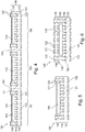
- a method of manufacturing component carriers comprises carrying out a test for each of multiple sections of a component carrier structure, inserting at least one functional component in each of further sections of a further component carrier structure to be connected with the component carrier structure so that each further section assigned to a respective section having successfully passed the test is provided with at least one functional component, and inserting at least one functionally inactive dummy component in each of the further sections assigned to a respective section having failed the test.
- a semifinished product obtainable or obtained during manufacturing component carriers comprises a component carrier structure comprising a plurality of functional sections and at least one non-functional section, a further component carrier structure connected with the component carrier structure and comprising a plurality of further sections, functional components each of which being inserted in a respective one of the further sections so that each further section assigned to a respective functional section is provided with at least one of the functional components, and at least one functionally inactive dummy component inserted in a respective one of the further sections so that each further section assigned to a respective non-functional section is provided with at least one dummy component.
- a component carrier comprising a component carrier section, a further component carrier section, a functional component embedded in the further component carrier section, and an additively manufactured (in particular a printed) connection structure by which the component carrier section and the further component carrier section are con nected.
- a method of manufacturing a component carrier comprises providing a component carrier section of a component carrier structure and a further component carrier section of a further component carrier structure being separate from said component carrier structure, embedding a functional component in the further component carrier section, forming by additive manufacturing (in particular printing) a connection structure on at least one of the component carrier section and the further component carrier section, and connecting the component carrier structure with the further component carrier structure so that the component carrier section and the further component carrier section are connected by the connection structure formed by additive manufacturing (in particular printing).
- a program element for instance a software routine, in source code or in executable code
- a processor such as a microprocessor or a CPU
- a computer-readable medium for instance a CD, a DVD, a USB stick, an SD card, a floppy disk or a hard disk, or any other (in particular also smaller) storage medium
- a computer program is stored which, when being executed by a processor (such as a microprocessor or a CPU), is adapted to control or carry out a method having the above mentioned features.
- Data processing which may be performed according to embodiments of the invention can be realized by a computer program, that is by software, or by using one or more special electronic optimization circuits, that is in hardware, or in hybrid form, that is by means of software components and hardware components.
- component carrier may particularly denote any support structure which is capable of accommodating one or more components thereon and/or therein for providing mechanical support and/or electrical connectivity.
- a component carrier may be configured as a mechanical and/or electronic carrier for components.
- a component carrier may be one of a printed circuit board, an organic interposer, and an IC (integrated circuit) substrate.
- a component carrier may also be a hybrid board combining different ones of the above mentioned types of component carriers.
- component carrier structure may particularly denote a preform of part of multiple component carriers as obtained during manufacturing component carriers.
- a component carrier structure may be a panel integrally comprising multiple preforms of component carriers being presently manufactured. It is also possible that such a panel is separated into multiple arrays (for instance into four quarter panels), wherein each array comprises multiple preforms of component carriers being presently manufactured.
- Such a panel or array may be a layer stack of multiple electrically conductive layer structures and/or electrically insulating layer structures, which may or may not have cavities and which may or may not be fully cured or at least partially uncured.
- a component carrier structure may particularly be any body (in particular layer stack) which may be used during the manufacture of component carriers and which may form part of a readily manufactured component carrier or multiple readily manufactured component carriers.
- the term "assigning" sections of the component carrier structures to be connected may particularly denote that the assigned sections are spatially assigned so as to face each other in a semifinished product composed of the component carrier structures. After singularization of the semifinished product, a corresponding functionally active or inactive component carrier may comprise the assigned sections.
- test of sections of a component carrier structure may particularly denote a functional test of the respective section.
- a test may be an electric test during which at least one electric stimulus signal is applied to an electrically conductive layer structure of the section and at least one electric response signal is detected being indicative of whether the section electrically functions or not.
- the test can be, additionally or alternatively, also a mechanical test testing the robustness, warpage properties, etc. of the section. Also a visual inspection is possible.
- connection structure may particularly denote any medium capable of connecting different component carrier structures with one another so as to obtain a common integral body.
- the term "component” may particularly denote any body, in particular having an electronic and/or thermal and/or mechanical function, being embedded in or surface-mounted on a layer stack, component carrier structure or component carrier.
- the component may be of a non-layer type, i.e. may not be as flat as the layer structures forming the stack.
- the component may extend vertically over multiple layer structures of a stack.
- the component may be made of a material at least partially deviating from component carrier material.
- the component may be a semiconductor chip.
- the term "functional component” may particularly denote a component which is capable of fulfilling a specific, in particular electronic or thermal, function.
- a functional component may be a semiconductor chip fulfilling a certain electronic function.
- a functional component may be a semiconductor package, i.e. bare die encapsulated in epoxy mold compound, fulfilling a certain electronic function.
- the functional component is a copper block for cooling purposes.
- the functional component may have already successfully passed a functioning test during which it has been successfully tested that the functional component is intact and thus capable of providing the assigned function.
- the term "dummy component" may particularly denote a physical body without function in terms of a component carrier.
- a dummy component may be simply a placeholder filling a cavity or recess of a component carrier structure for avoiding problems during processing (in particular lamination) which might arise if the cavities would not be filled by a functional component or a dummy component.
- the dummy component may be incapable of providing any function or at least the function provided by the functional components.
- a dummy component may be a body (for instance of plastic or silicon) being functionally inactive in a semifinished product or a readily manufactured component carrier.
- the dummy component may be incapable of providing any electric function.
- the dummy component may simply emulate the shape of a functional component.
- the dummy component may be shaped and dimensioned as a functional component however without providing the function of the functional component.
- the dummy component is a non-functional component, i.e. is a component which has however failed to pass a functioning test before being inserted in cavities of the further component carrier structure.
- the term "known-good” may particularly denote that a structure (such as a layer stack, a cavity, a component or a component carrier) being considered for manufacturing a component carrier or a system of multiple component carriers has already previously, i.e. before using, mounting or assembling the respective constituent, been successfully tested concerning its qualification to contribute to the formation of a failure-free component carrier or system and has therefore successfully passed such a test.
- a test may be a quality test testing this qualification.
- the quality test may test as to whether the respective structure fulfils a predefined specification, is within a predefined range of tolerances, and/or complies with a predefined functional requirement.
- Such a quality test may be an electric test which may for instance involve applying an electric stimulus signal and measuring an electric response signal which must fulfil certain conditions in order to consider the respective structure to have passed the test.
- Such a test may, additionally or alternatively, be also an inspection (for instance an optical inspection) measuring shape and/or dimension of a respective structure as at least part of the test.
- an inspection for instance an optical inspection
- the respective structure may for instance be disposed as waste, or may be made subject to a repair or post-processing procedure or may be used for another purpose.
- the term "layer stack” may particularly denote a stack of multiple planar layer structures being connected to one another.
- such layer structures may be electrically insulating layer structures and/or electrically conductive layer structures.
- the term "layer structure" may particularly denote one of a continuous layer, a patterned layer and an arrangement of multiple connected and/or non-connected islands within one plane.
- a layer structure may be a continuous foil or sheet, whereas such a foil or sheet may also be patterned.
- the layer structures or the stack as a whole may comprise component carrier material, i.e. material used for electrically conductive structures or electrically insulating structures of a component carrier such as a printed circuit board or an IC substrate.
- the individual layer structures of the stack may be connected in particular by lamination, i.e. the application of heat and/or pressure.
- additive manufacturing may particularly denote a manufacturing procedure of a connection structure according to which the connection structure is manufactured by the addition of material (in particular sequential addition of portions of material) which constitute the connection structure.
- Additive manufacturing may in particular encompass printing, more particularly three-dimensionally printing.
- a high yield manufacturing method for multilayer component carriers with embedded component in which a component carrier structure is connected with a further component carrier structure.
- functional components can be only inserted in sections of the further component carrier structure which will be connected with a known-good section of the component carrier structure.
- a successful test is completed indicating that said section of the component carrier structure functions properly.
- cavities in further sections of the further component carrier structure which correspond to or are assigned to sections of the component carrier structure having failed the test are filled with dummy components mimicking a respective functional component without requiring to fulfil a functional component's function.
- dummy components mimicking a respective functional component without requiring to fulfil a functional component's function.
- the reliability of the manufactured component carriers may be improved.
- a high yield of functionally active component carriers singularized from the semifinished product can be synergistically combined with a proper processability of the semifinished product during the manufacturing process.
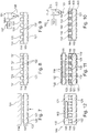
- a gist of an exemplary embodiment of the invention may be the recombination, in z-direction, of a fully tested circuit board, as first component carrier structure, with an embedded core circuit board, as second component carrier structure, having known-good components placed according to the known-good component carrier sections of the first component carrier structure.
- a combination of a fully tested core with a fully tested PCB may allow for a high yield production.
- a die-last embedding technology may be provided which allows obtaining specifically pronounced advantages where fan-out or formation of a redistribution layer is assembled last.
- the combination of a z-interconnection method and a layer with embedded components may be advantageous in order to match the known-good component carrier sections with known-good components.
- Combining pre-tested electronic blocks for example HDI (high density integration) and embedded cores) can bring substantial advantages in terms of higher yield, hence, costs.
- a dielectric layer of a connection structure for z-interconnection may be formed by additive manufacturing, in particular may be printed (for instance screen printed, inkjet printed, etc.). During such a printing procedure, openings (for instance via-like openings) may be formed in which conductive layers may be printed/dispensed or formed by another additive manufacturing process. In particular, one or more printed dielectric sheets with openings in which conductive layers may be printed and/or dispensed may be provided as vias for z-interconnection. However, also other additive manufacturing processes may be applied for forming the connection structure or part thereof.
- a corresponding software may provide a traceability and data analytics function to enable the method according to exemplary embodiments of the invention as well as communication in between involved machinery. Assembling of components, manufacturing a component carrier structure with functional components therein, etc., may be processed by referring to stored (in particular emap, etest, imaging, test and/or other) data. Known good components and/or dummies may then be chosen accordingly. In particular, such a software may also control or carry out a measurement of shape and/or dimension of a respective structure as at least part of the above-mentioned test.
- an exemplary embodiment of the invention provides a method of combining known-good electronic components.
- the re-combination or assembly of two or more component carrier structures may the obtained using (i) copper paste for establishing conductive paths in z-direction and (ii) a B-stage (i.e. not fully cured) resin sheet for mechanical adhesion, both in between the two component carrier structures.
- the mentioned PCB can be a substrate, a PCB with embedded component, a core with embedded components, etc.
- the component carrier structure is a panel, or an array comprising multiple preforms of component carriers.
- the term "panel" may particularly denote a planar layer stack of at least one electrically insulating layer structure and/or at least one electrically conductive layer structure and having a format capable of manufacturing multiple component carriers. For instance, such a panel may have an area of 18 x 12 inches 2 , or larger.
- An array may be a portion of a panel including multiple preforms of component carrier in a block.
- the further component carrier structure is a core having cavities in which the functional components and the dummy components are embedded.
- the term "core” may particularly denote a fully cured layer stack made of component carrier material.
- such a core may be made of FR4 material, optionally in combination with copper structures.
- formation of cavities in the core is possible without the risk of resin flowing into the cavities during a lamination procedure.
- the cavities may be sized and shaped so as to be capable of accommodating functional components or dummy components.
- the method comprises connecting the component carrier structure with the further component carrier structure by a connection structure.
- a layer stack with multiple layers can be formed by connecting the two component carrier structures with one another via the connection structure.
- the connection structure may establish a mechanical connection between the component carrier structure and the further component carrier structure.
- the connection structure additionally provides an electric connection between electrically conductive structures of the connected component carrier structures. For instance, such an electric connection may form an electrically conductive path from a functional component in the further component carrier structure into the component carrier structure. It has turned out that the yield of manufacturing component carriers with multiple layer structures is higher when connecting two (or more) component carrier structures each comprising a respective layer stack as compared to a build-up of a single layer stack by continued lamination or the like.
- each of the component carrier structures connected by the connection structure may have at least 6, in particular at least 10, more particularly at least 14 layer structures, thereby enabling to form component carriers of a very high number of layer structures with high yield.
- the method comprises printing the connection structure on one or both of the component carrier structure and the further component carrier structure.
- the connection structure may be printed on the respective component carrier structure.
- connection structure not only allows defining electrically insulating regions of the connection structure (for instance by applying dielectric adhesive).
- electrically conductive regions are defined by printing (for instance by printing an electrically conductive paste on desired portions of a respective one of the component carrier structures).
- the printing comprises one of the group consisting of ink jetting, screen printing, and dispensing.
- a medium supply device providing the medium of the connection structure.
- Such embodiments of the invention may be implemented with various kinds of medium supply devices such as dispensing devices, screen-printing devices, inkjet devices, aerosol jet devices, etc.
- the mentioned medium supply device may be configured for supplying material of the connection structure.
- any appropriate liquid, solid, aerosol, etc. medium can be applied to a connection surface of the respective component carrier structure.
- the medium supply device is a dispenser.
- a dispenser may comprise a tubular member with a hollow lumen through which medium to be dispensed or applied can be transported. At an open flange face of an end section of such a dispenser, the medium may pass out of the tubular member onto a surface portion of the respective component carrier structure.
- the medium supply device is a screen-printing device.
- a screen-printing device may comprise a screen with at least one through hole as medium supply opening through which medium to be dispensed or applied can be transported. At least part of the screen may be placed on the connection surface of the respective component carrier structure to partially cover the latter. Subsequently, medium to be applied may be supplied from an upper side of the screen and may pass at one or more defined positions through the at least one through hole (which may define a pattern according to which the medium shall be applied to only selective surface portions of the cavity wall). A squeegee may then move over the screen to promote passage of medium through the at least one through hole and to remove excessive medium from an upper side of the screen.
- the printed connection structure is free of a reinforcing structure, in particular free of reinforcing particles or reinforcing fibers.
- reinforcing glass fibers or glass spheres may not form part of the printed connection structure.
- the material of the printed connection structure may be different from prepreg or FR4 being applied as a layer of resin with reinforcing particles therein.
- the printed connection structure may for instance consist of resin or other materials such as epoxy derivatives which do not comprise a reinforcing structure.
- the method comprises laminating the connection structure, made of an at least partially uncured material, on one of the component carrier structure and the further component carrier structure so that the connection structure remains at least partially uncured after the laminating, and subsequently laminating together, by the connection structure, the component carrier structure and the further component carrier structure.
- the method may comprise substantially fully curing (in particular fully curing) the connection structure by the subsequent lamination.
- the polymer chains are highly crosslinked during curing so that the final component carrier cannot be thermally reformed.
- the connection structure may also be formed by soft lamination (i.e. lamination which does not fully cure the material of the connection structure) followed by an optional patterning of a layer forming the connection structure.
- the material of the connection structure may then be fully cured.
- Lamination may be carried out by applying thermal energy and/or mechanical pressure.
- the method comprises connecting another component carrier structure with the component carrier structure and the further component carrier structure by another connection structure (wherein the other connection structure may be configured in accordance with any of the embodiments described above for the connection structure connecting the component carrier structure with the further component carrier structure).
- the stacking architecture according to an exemplary embodiment of the invention may be continued by, subsequently or simultaneously, connecting at least one further component carrier structure to the component carrier structure and the further component carrier structure. Therefore, even highly complex component carriers with a high number of layer structures may be formed.
- individual sections of the other component carrier structure may be functionally tested before connecting it to the component carrier structure and the further component carrier structure.
- individual sections of the other component carrier structure assigned with the sections of the component carrier structure and the further sections of the further component carrier structure may be functionally tested before the connection.
- only sections of the component carrier structure and assigned sections of the other component carrier structure which have successfully passed the functional tests may then be connected with a corresponding further section of the further component carrier structure in which a functional component is embedded. If any of the mentioned sections turns out as functionally problematic, the respective cavity in the assigned further section of the further component carrier structure may be filled with a dummy component instead of filling it with a functional component.
- the further component carrier structure may be arranged between the component carrier structure and the other component carrier structure.
- the one or more functional components may be embedded deeply in an interior of a multilayer stacked component carrier.
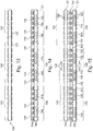
- the method comprises separating a semifinished product obtained by connecting the component carrier structure with the further component carrier structure into individual component carriers each comprising one of the sections and a one of the further sections and one of a functional component or a dummy component. Also a portion of the connection structure may form part of each component carrier.
- the separated sections comprising a functional component may then be used as readily manufactured component carriers.
- the obtained singularized bodies having a dummy component only will not be used as component carrier structures. They may be considered as waste or may be further processed to recover the embedded dummy component for further procedures.
- the loss of functional components due to functionally problematic connected sections may be significantly reduced, or even eliminated.
- the method comprises providing the connection structure as a patterned electrically insulating layer structure (in particular comprising at least partially uncured resin) having at least one recess filled with an electrically conductive material (in particular copper paste).
- an electrically conductive material in particular copper paste.
- the method comprises treating the component carriers comprising a dummy component as waste.
- the dummy components may also be recycled from these non-functional component carrier.
- the method comprises carrying out a test for each of the functional components before the inserting, and inserting the functional components in a respective one of the further sections only for those functional components having passed the testing.
- each of the component carrier structure and the further component carrier structure comprises a stack comprising at least one electrically insulating layer structure and/or at least one electrically conductive layer structure. This allows connecting multiple multi-layer stacks with one another to form component carriers having a high layer count.
- the component carrier comprises a stack of at least one electrically insulating layer structure and at least one electrically conductive layer structure.
- the component carrier may be a laminate of the mentioned electrically insulating layer structure(s) and electrically conductive layer structure(s), in particular formed by applying mechanical pressure and/or thermal energy.
- the mentioned stack may provide a plate-shaped component carrier capable of providing a large mounting surface for further components and being nevertheless very thin and compact.
- layer structure may particularly denote a continuous layer, a patterned layer or a plurality of non-consecutive islands within a common plane.
- the component carrier is shaped as a plate. This contributes to the compact design, wherein the component carrier nevertheless provides a large basis for mounting components thereon. Furthermore, in particular a naked die as example for an embedded electronic component, can be conveniently embedded, thanks to its small thickness, into a thin plate such as a printed circuit board.
- the component carrier is configured as one of the group consisting of a printed circuit board, a substrate (in particular an IC substrate), and an interposer.
- the term "printed circuit board” may particularly denote a plate-shaped component carrier which is formed by laminating several electrically conductive layer structures with several electrically insulating layer structures, for instance by applying pressure and/or by the supply of thermal energy.
- the electrically conductive layer structures are made of copper
- the electrically insulating layer structures may comprise resin and/or glass fibers, so-called prepreg or FR4 material.
- the various electrically conductive layer structures may be connected to one another in a desired way by forming through-holes through the laminate, for instance by laser drilling or mechanical drilling, and by filling them with electrically conductive material (in particular copper), thereby forming vias as through-hole connections.
- a printed circuit board is usually configured for accommodating one or more components on one or both opposing surfaces of the plate-shaped printed circuit board. They may be connected to the respective main surface by soldering.
- a dielectric part of a PCB may be composed of resin with reinforcing fibers (such as glass fibers).
- the term "substrate” may particularly denote a small component carrier having substantially the same size as a component (in particular an electronic component) to be mounted thereon. More specifically, a substrate can be understood as a carrier for electrical connections or electrical networks as well as component carrier comparable to a printed circuit board (PCB), however with a considerably higher density of laterally and/or vertically arranged connections. Lateral connections are for example conductive paths, whereas vertical connections may be for example drill holes. These lateral and/or vertical connections are arranged within the substrate and can be used to provide electrical and/or mechanical connections of housed components or unhoused components (such as bare dies), particularly of IC chips, with a printed circuit board or intermediate printed circuit board. Thus, the term “substrate” also includes "IC substrates". A dielectric part of a substrate may be composed of resin with reinforcing particles (such as reinforcing spheres, in particular glass spheres).
- the substrate or interposer may comprise or consist of at least a layer of glass, silicon (Si) or a photoimageable or dry-etchable organic material like epoxy-based build-up material (such as epoxy-based build-up film) or polymer compounds like polyimide, polybenzoxazole, or benzocyclobutene.
- Si silicon
- a photoimageable or dry-etchable organic material like epoxy-based build-up material (such as epoxy-based build-up film) or polymer compounds like polyimide, polybenzoxazole, or benzocyclobutene.
- the at least one electrically insulating layer structure comprises at least one of the group consisting of resin (such as reinforced or non-reinforced resins, for instance epoxy resin or Bismaleimide-Triazine resin), cyanate ester, polyphenylene derivate, glass (in particular glass fibers, multi-layer glass, glass-like materials), prepreg material (such as FR4 or FR5), polyimide, polyamide, liquid crystal polymer (LCP), epoxy-based build-up film, polytetrafluoroethylene (teflon), a ceramic, and a metal oxide.
- Reinforcing materials such as webs, fibers or spheres, for example made of glass (multi-layer glass) may be used as well.
- prepreg particularly FR4 are usually preferred for rigid PCBs
- other materials in particular epoxy-based build-up film for substrates may be used as well.
- highfrequency materials such as polytetrafluoroethylene, liquid crystal polymer and/or cyanate ester resins, low temperature cofired ceramics (LTCC) or other low, very low or ultra-low DK materials may be implemented in the component carrier as electrically insulating layer structure.
- At least one of the electrically conductive layer structures comprises at least one of the group consisting of copper, aluminum, nickel, silver, gold, palladium, and tungsten.
- copper is usually preferred, other materials or coated versions thereof are possible as well, in particular coated with supra-conductive material such as graphene.
- At least one functional component may embedded in the component carrier and can in particular be selected from a group consisting of an electrically non-conductive inlay, an electrically conductive inlay (such as a metal inlay, preferably comprising copper or aluminum), a heat transfer unit (for example a heat pipe), a light guiding element (for example an optical waveguide or a light conductor connection), an electronic component, or combinations thereof.
- an electrically non-conductive inlay such as a metal inlay, preferably comprising copper or aluminum
- a heat transfer unit for example a heat pipe
- a light guiding element for example an optical waveguide or a light conductor connection
- an electronic component or combinations thereof.
- the component can be an active electronic component, a passive electronic component, an electronic chip, a storage device (for instance a DRAM or another data memory), a filter, an integrated circuit, a signal processing component, a power management component, an optoelectronic interface element, a light emitting diode, a photocoupler, a voltage converter (for example a DC/DC converter or an AC/DC converter), a cryptographic component, a transmitter and/or receiver, an electromechanical transducer, a sensor, an actuator, a microelectromechanical system (MEMS), a microprocessor, a capacitor, a resistor, an inductance, a battery, a switch, a camera, an antenna, a logic chip, and an energy harvesting unit.
- a storage device for instance a DRAM or another data memory
- a filter for instance a DRAM or another data memory
- an integrated circuit for instance a DRAM or another data memory
- a signal processing component for instance a DC/DC converter or an AC/DC
- a magnetic element can be used as a component.
- a magnetic element may be a permanent magnetic element (such as a ferromagnetic element, an antiferromagnetic element or a ferrimagnetic element, for instance a ferrite core) or may be a paramagnetic element.
- the component may also be a substrate, an interposer or a further component carrier, for example in a board-in-board configuration.
- a component may be surface mounted on the component carrier and/or may be embedded in an interior thereof.
- other components in particular those which generate and emit electromagnetic radiation and/or are sensitive with regard to electromagnetic radiation propagating from an environment, may be used as component.
- the component carrier is a laminate-type component carrier.
- the component carrier is a compound of multiple layer structures which are stacked and connected together by applying a pressing force and/or heat.
- a method of combining known-good component carrier structures is provided.
- the total yield of highly complex component carrier systems can be significantly increased compared to conventional approaches.
- a die-last embedding architecture may be implemented, in particular where a fan-out structure or a redistribution layer is assembled last.
- a high layer count board recombination may be achieved, for instance based on advanced HDI (high density interconnect) technology.
- PCBs printed circuit boards
- Such a PCB can also be an IC (integrated circuit) substrate, a PCB with embedded component, a core with embedded component, etc.
- copper paste may be used in a connection structure between different component carrier structures for establishing conductive paths in vertical direction. It is also possible to use an at least partially uncured electrically insulating layer structure (such as a B-stage resin sheet) for mechanical adhesion between multiple component carrier structures, i.e. in between the electronic component carrier structures.
- an at least partially uncured electrically insulating layer structure such as a B-stage resin sheet
- a yield improvement obtainable according to exemplary embodiments of the invention may be described as follows: In case of high layer count PCBs, each additional layer (where the yield is not 100%) may lead to waste, what concerns full cards realized with the previous lay-up. Therefore, it is to be expected that manufacturing (for example) a 28 layer PCB by subsequent lamination procedures may lead to a lower yield compared to combining two 14 layer PCBs together.
- a fully tested component carrier structure such as a printed circuit board
- a further embedded core component carrier structure having known-good functional components placed according to the known-good parts in the first mentioned component carrier structure.
- a dielectric connection layer providing a vertical interconnection between the two mentioned component carrier structures may be printed (for instance screen printed, printed by inkjet, etc.). Openings (for instance via-like openings) may be left where the conductive layers may be printed or dispensed.
- the production of a high layer count component carrier is carried out by a recombination of two or more component carrier structures.
- a PCB structure with embedded components may be combined with a further PCB structure for interconnection purposes.
- a significant advantage which may be obtained by such a concept is to thoroughly test one PCB structure before lamination with the other PCB structure in order to identify possible failure zones. Therefore, identifying defect units on the whole panel is possible.
- an embedded core containing known-good (i.e. fully tested) components and dummy components may be prepared. The dummy components may be positioned on the carriers matching those defect units pre-tested on the PCB structure.
- An additional product which can be manufactured according to an exemplary embodiment of the invention is an electronic module based on different combination levels, for instance an embedded core in the middle and two PCB structures, i.e. one on top side and one on bottom side of the embedded core.
- the different component carrier structures may be connected to one another by soft lamination.
- a lamination layer i.e. a not fully cured layer
- the two component carrier structures may be connected with one another via the soft lamination layer. More specifically, this may be accomplished by fully curing the previously only partially cured lamination layer. This may be done by lamination, i.e. the application of thermal energy and/or mechanical pressure to the previously only partially cured electrically insulating layer structure between the two component carrier structures to be connected.
- the mentioned soft lamination process can be applied on either of the PCB structures (for instance to an embedded core). Further combinations of multiple level component carrier structures can be realized depending on how many modules shall be combined in a certain application.
- a chip-last manufacturing architecture may be provided in combination with center core embedding.
- center core embedding By softly laminating a resin sheet on the center core board of the PCB to be combined with, better design rules can be achieved than with conventional approaches.
- a chip-last architecture may decrease the waste of components by combining known-good dies with known-good sections or component carrier units.
- chip-last embedding can be carried out highly advantageously or in high layer boards. Exemplary applications of exemplary embodiments of the invention relate to Wi-Fi modules, Bluetooth modules, radio frequency power amplifiers, etc.
- an exemplary embodiment of the invention may provide a board-to-board connection manufacturing architecture combining a pre-tested electronic block (for instance a high density integration block) of a first component carrier structure and an embedded core as second component carrier structure for obtaining substantial advantages in terms of yield and manufacturing effort.
- a pre-tested electronic block for instance a high density integration block
- Figure 1 to Figure 4 illustrate cross-sectional views of structures obtained during carrying out a method of manufacturing component carriers 100 according to an exemplary embodiment of the invention.
- a panel type component carrier structure 104 is shown which is composed of multiple sections 102. Each of the sections 102 corresponds to a portion of the component carrier structure 104 which forms part of a readily manufactured separate component carrier 100 (compare Figure 4 and Figure 5 ).
- the component carrier structure 104 may be a panel or an array comprising multiple preforms of component carriers 100.
- the component carrier structure 104 comprises a planar laminated stack 118 comprising for instance a central electrically insulating layer structure 121 covered on both opposing main surfaces with a respective electrically conductive layer structure 122.
- the electrically insulating layer structure 121 may comprise resin (in particular epoxy resin), optionally comprising reinforcing particles such as glass fibers or glass particles.
- the electrically conductive layer structures 122 may for instance be metal layers such as copper foils.
- the stack 118 of the component carrier structure 104 comprises for example 14 layer structures.
- a function test may be carried out for each of multiple sections 102 of the component carrier structure 104 individually.
- the sections denoted with reference numeral 102 have successfully passed the functional test, whereas the section denoted with reference numeral 140 has failed the functional test.
- Figure 1 shows a component carrier structure 104 with multiple sections 102, 140 which have undergone an individual electric test concerning their functioning. The result of this test has been that the sections labelled 102 have passed this functional electric test and can therefore be used for manufacturing functionally intact component carriers 100. However, the section labelled 140 has failed this electric test and cannot be used as part of a functionally intact component carrier 100.
- Figure 2 the component carrier structure 104 of Figure 1 is shown together with an attached connection structure 114. Furthermore, Figure 2 illustrates a further component carrier structure 106 which is aligned with regard to the component carrier structure 104. The further component carrier structure 106 is to be connected with the component carrier structure 104 by the connection structure 114.
- the further component carrier structure 106 comprises a planar laminated stack 118 comprising for instance a central electrically insulating layer structure 121 covered on both opposing main surfaces with a respective electrically conductive layer structure 122.
- the stack 118 of the further component carrier structure 106 comprises for example 14 layer structures.
- the electrically insulating layer structure 121 of the further component carrier structure 106 may comprise resin (in particular epoxy resin), optionally comprising reinforcing particles such as glass fibers or glass particles.
- the electrically conductive layer structures 122 of the further component carrier structure 106 may for instance be metal layers such as copper foils.
- the further component carrier structure 106 comprises a core 124 having cavities 126 in which functional components 110 and dummy components 112 are embedded, as described below in detail. The core 124 corresponds to the stack 118 of the further component carrier structure 106.
- No dummy components 112 are inserted into further sections 108 corresponding to sections 102 having passed the function test.
- a functional test can also be carried out individually for each of the functional components 110 before inserting the functional components 110 in the cavities 126 of the further component carrier structure 106.
- the functional components 110 are inserted into respective ones of the further sections 108 only if the respective functional component 110 has previously passed the functional tests successfully.
- no functional component 110 is inserted in the further section 108 assigned to section 140 having failed the test.
- no dummy components 112 are inserted in each of the further sections 108 assigned to a respective section 102 having successfully passed the test.
- the process of embedding components in the cavities 126 of the further component carrier structure 106 can be adapted correspondingly.
- the further sections 108 of the further component carrier structure 106 which are aligned and therefore assigned to a corresponding section 102 of the component carrier structure 104 are filled with a known-good functional component 110, i.e. a component having passed a functional test before embedding.
- a known-good functional component 110 i.e. a component having passed a functional test before embedding.
- the functional components 110 are semiconductor chips which have successfully passed a corresponding functioning test which may be carried out by a test device (not shown).
- another section 108 of the further component carrier structure 106 which is spatially and functionally assigned to section labelled 140 of the component carrier structure 104 which has failed the electric test will only be equipped with a functionally inactive dummy component 112 rather than with a functional component 110.
- the dummy components 112 may be shaped and dimensioned like the functional components 110 but do not provide the function of the functional components 110. Since the corresponding section 140 is not usable for a component carrier 100, the corresponding section 108 of the further component carrier structure 106 will also be waste.
- the respective cavity 126 is not filled with an expensive functional component 110 but with an identically shaped and dimensioned, but functionally inactive further dummy component 112.
- known-good sections 102 are connected with sections 108 accommodating known-good functional components 110.
- known-bad sections 140 of the component carrier structure 104 are combined with dummy components 112 of the further component carrier structure 106.
- Dummy components 112 may be totally inactive space holders, as long as they are shaped and dimensioned as functional components 110.
- Dummy components 112 may show similar properties (for instance with regard to stability, rigidity or flexibility, surface roughness, thermal behavior, etc.) at the time of the component carrier 100 being fabricated. It may be possible to choose such dummy components 112 with the same properties as described above, but much shorter durability, degradation, easier recyclability, etc., as the dummy components 112 are only needed as space holders and may be optionally recycled afterwards.
- connection structure 114 is here embodied as a patterned electrically insulating layer structure 120 comprising at least partially uncured resin and having an array of recesses filled with an electrically conductive material 132 in form of copper paste.
- the connection structure 114 may be formed by printing, as illustrated and described in further detail in Figure 9 and Figure 10 . Printing the connection structure 114 on the component carrier structure 104 allows the precise definition of electrically insulating regions (compare reference numeral 120) and electrically conductive regions (compare reference numeral 132) of the connection structure 114.
- each of the functional component 110 comprises electrically conductive terminals 123 (such as pads) having an exterior non-copper surface connected to the printed connection structure 114.
- the embedded component 110 is not necessarily provided with a copper termination as normally needed for center core embedding.
- the contact termination material on component level is not an issue, as paste can be used to interconnect the two component carrier structures 104, 106. Additional effort involved with conventional PCB processes such as laser drilling, desmearing, electroless copper, etc., which are compatible only with copper terminated surfaces, may therefore be dispensable.
- connection structure 114 the result of the connection of the component carrier structures 104, 106 by the connection structure 114 described above is shown as semifinished product 134. This connection can be established by lamination.
- the semifinished product 134 comprises the component carrier structure 104 with the plurality of functional sections 102 and the non-functional section 140. Also the further component carrier structure 106, being connected with the component carrier structure 104, forms part of the semifinished product 134.
- the functional components 110 are inserted in some of the further sections 108 so that each further section 108 assigned to a respective functional section 102 is provided with one of the functional components 110.
- a functionally inactive dummy component 112 is inserted in further section 108 being assigned to non-functional section 140 having failed the functional test of the individual sections 102, 140 of the component carrier structure 104.
- the semifinished product 134 shown in Figure 3 can be obtained by laminating the structures shown in Figure 2 together, in particular by applying pressure and heat. Thereby, the electrically insulating layer structure 120 of the connection structure 114 may be cured.
- the electrically insulating layer structure 120 may be previously uncured resin with polymers which cross-link in the presence of heat and pressure. Thereby, the resin becomes fully cured and thereby adheres component carrier structures 104, 106 to one another.
- the electrically conductive material 132 in the shown embodiment a copper paste, may be cured by this lamination procedure. For instance, a solvent in the copper paste may evaporate so that the remaining copper particles are connected to one another by sintering and provide a reliable electric connection between the opposing component carrier structures 104, 106.
- the left-hand side of Figure 3 also illustrates (in contrast to Figure 1 and Figure 2 ) a further feature according to an exemplary embodiment of the invention.
- the component carrier 100 shown on the left-hand side which may be formed based on center core embedding, can have component pads or terminals 123 facing directly outside (i.e. without further layer on top).
- d i.e. the pad center to pad center distance
- the semifinished product 134 is singularized into multiple functionally active component carriers 100 and a functionally inactive component carrier 100'.
- Separation lines 199 indicate how the semifinished product 134 according to Figure 4 is separated into functionally active component carriers 100 and a functionally inactive component carrier 100'. Separation along lines 199 may be accomplished by mechanically cutting, by laser cutting, or by chemical etching.
- the component carrier 100' comprising the dummy component 112 may be classified as waste.
- the component carriers 100 may be operated in accordance with a corresponding application.
- the component carriers 100 In view of the combination of known-good sections 102 with known-good functional components 110, the component carriers 100 have a high likelihood of being functionally usable without reliability issues.
- the component carrier 100' in view of the combination of known-bad section 140 with known-bad dummy component 112, the component carrier 100' is functionally inactive and can be classified as waste.
- the component carrier 100' can be made subject to a recycling procedure, for instance for recovering the dummy component 112 to be used in a subsequent procedure of manufacturing a further batch of component carriers 100.
- Figure 5 illustrates a cross-sectional view of such a component carrier 100 according to an exemplary embodiment of the invention which has been obtained by the manufacturing procedure according to Figure 1 to Figure 4 .
- the shown component carrier 100 comprises a component carrier section 102, a further component carrier section 108, a functional component 110 embedded in the further component carrier section 108, and a part of printed and now cured connection structure 114 by which the component carrier section 102 and the further component carrier section 102 are connected.
- Figure 5 thus shows a component carrier 100 as obtained after the singularization procedure described referring to Figure 4 .
- Figure 6 illustrates a cross-sectional view of a component carrier 100 according to another exemplary embodiment of the invention.
- the component carrier 100 according to Figure 6 comprises an additional procedure during its manufacture.
- another component carrier structure 128 (which may be constructed in a similar way as component carrier structure 104 or a section 102 thereof) is connected with the semifinished product 134 composed of the component carrier structure 104 and the further component carrier structure 106 (or a portion thereof).
- another connection structure 130 may be used, which can be configured correspondingly to the connection structure 114 shown in Figure 2 or according to any other embodiment of the connection structure described herein.
- Figure 6 shows a component carrier 100 according to another exemplary embodiment in which not only two component carrier structures 104, 106 are interconnected during a batch manufacture of component carriers 100, but another component carrier structure 128 has been connected to the further component carrier structure 106 with the embedded functional components 110. Therefore, a particularly high layer account may be obtained in the component carrier 100 according to Figure 6 while nevertheless having a high yield. Also sections of the other component carrier structure 128 may be connected with sections having functional components 110 only after a successful functioning test of the respective section of the other component carrier structure 128.
- Figure 7 to Figure 12 show cross-sectional views of structures obtained during carrying out a method of manufacturing component carriers 100 according to an exemplary embodiment of the invention.
- connection structure 114 made of an at least partially uncured material such as not yet cross linked epoxy resin, is softly laminated on the component carrier structure 104 or section 102 thereof, so that the connection structure 114 remains at least partially uncured after the laminating. More precisely, this connection of the connection structure 114 to the component carrier structure 104 or section 102 may involve an only partial cross-linking and hence only partial curing of the material of the electrically insulating layer structure 120. Such a soft lamination may be accomplished by applying a sufficiently moderate amount of heat and/or a sufficiently moderate amount of pressure.
- the soft laminated electrically insulating layer structure 120 can still be used for interconnection of section 102 with further section 108 in a later lamination procedure (see Figure 11 ).
- Figure 8 shows the result of a patterning of the electrically insulating layer structure 120 so as to expose electrically conductive layer structure 122 on an exterior surface of the component carrier structure 104 or section 102.
- Patterning may be accomplished, for example, by laser drilling, optionally in combination with a subsequent dry etching procedure. Alternatively, the patterning may be carried out by lithography and chemical etching.
- the patterning and resulting exposure of the electrically conductive layer structures 122 allows for an electric connection of this now exposed electrically conductive layer structure 122 with a corresponding electrically conductive layer structure 122 of the further component carrier structure 104 or a section 108 thereof (compare Figure 11 and Figure 12 ).
- connection structure 114 is printed on the component carrier structure 104 or section 102 in an already patterned way.
- this printing may be embodied as a dispensing.
- the connection structure 114 may comprise uncured resin (in particular epoxy resin).
- the printed connection structure 114 may be free of a reinforcing structure, in particular free of reinforcing glass fibers.
- connection structure 114 may also be applied by printing.
- a medium supply device 197 filled with a medium 195 to be supplied to the component carrier structure 102 for forming the connection structure 114 may be used.
- the medium supply device 197 can be controlled by a control unit 193.
- the medium supply device 197 can be moved along a main surface of the component carrier structure 104 or the section 102 so as to apply the connection structure 114 in accordance with a desired pattern.
- medium 195 can be applied to desired surface portions of the component carrier structure 104 or section 102 to thereby define the patterned connection structure 114 without carrying out a patterning procedure.
- the electrically insulating layer structure 120 of the connection structure 114 may be formed.
- electrically conductive material 132 is printed (for instance dispensed) selectively into the recesses 131 extending through the electrically insulating layer structure 120 of the connection structure 114.
- a further medium supply device 185 may be used for applying an electrically conductive medium 183 selectively to exposed surface portions of the electrically conductive layer structure 122.
- the medium 183 may be copper paste, which may optionally comprise an evaporable solvent or any other sacrificial material promoting proper application of medium 183.
- exposed electrically conductive portions of the electrically conductive layer structure 122 may be selectively covered with the electrically conductive material 132.
- exposed portions of the electrically conductive layer structure 122 shown in Figure 8 can also be filled with the electrically conductive paste 132 by the procedure described according to Figure 10 .
- connection structure 114 a subsequent lamination of the component carrier structure 104 (or the section 102) and the further component carrier structure 106 (or the section 108) by the connection structure 114 is illustrated.
- Figure 11 illustrates the connection of the component carrier structure 102 covered with the connection structure 114 shown in Figure 10 on the one hand and further component carrier structure 106 on the other hand.
- This connection may be carried out for example by the application of pressure and/or heat.
- the electrically insulating layer structure 120 of the connection structure 114 has been applied by soft lamination, the component carrier structure 114 may be fully cured by the additional lamination according to Figure 11 .
- the connection according to Figure 11 may be carried out by curing the connection structure 114, which can be accomplished as well by mechanical pressure and/or heat.
- Figure 12 shows the result of the complete lamination described referring to Figure 11.
- Figure 12 shows the obtained component carrier 100.
- a semifinished product 134 is obtained which still needs to be singularized (for instance in the way shown in Figure 4 ) to obtain individual component carriers 100.
- Figure 13 , Figure 14 , and Figure 15 show cross-sectional views of component carrier structures 104, 106 connected during carrying out a method of manufacturing component carriers 100 according to an exemplary embodiment of the invention.
- Figure 13 to Figure 15 show that the manufacturing process described referring to Figure 7 to Figure 12 can be carried out in a corresponding way also with multiple integrally formed component carrier structures 104, 106, i.e. on panel or array level.
- two functional components 110 are embedded in each obtained component carrier 100
- two dummy components 112 are embedded in each obtained non-functional component carrier 100'.
- the component carrier structures 104 and 106 can also be without components 110 when being connected. This is especially applicable in the case of highly complex panel structures (for instance many layers) for reducing a bad card/bad unit multiplicator. In that case, all units or sections 102, 108 of both component carrier structures 104, 106 can be tested prior to connecting them with one another. In that case, it may be possible to singularize and reconstruct one of the component carrier structures 104 or 106 to adjust it to the locations of the known good units or sections 102, 108 of the respective other component carrier structure 104 or 106.
Landscapes
- Engineering & Computer Science (AREA)
- Microelectronics & Electronic Packaging (AREA)
- Computer Hardware Design (AREA)
- Power Engineering (AREA)
- Manufacturing & Machinery (AREA)
- Physics & Mathematics (AREA)
- Condensed Matter Physics & Semiconductors (AREA)
- General Physics & Mathematics (AREA)
- Ceramic Engineering (AREA)
- Production Of Multi-Layered Print Wiring Board (AREA)
Priority Applications (4)
| Application Number | Priority Date | Filing Date | Title |
|---|---|---|---|
| EP19173014.2A EP3736852A1 (fr) | 2019-05-07 | 2019-05-07 | Alignement d'une structure de support de composants avec des sections réputées bonnes et d'une section critique avec un autre support de composants comportant des composants et des dispositifs factices |
| US15/929,330 US11430703B2 (en) | 2019-05-07 | 2020-04-27 | Aligning component carrier structure with known-good sections and critical section with other component carrier with components and dummies |
| CN202010373086.8A CN111918488A (zh) | 2019-05-07 | 2020-05-06 | 制造部件承载件的方法以及部件承载件 |
| US17/817,256 US20220377911A1 (en) | 2019-05-07 | 2022-08-03 | Method of Manufacturing Component Carrier and Component Carrier Intermediate Product |
Applications Claiming Priority (1)
| Application Number | Priority Date | Filing Date | Title |
|---|---|---|---|
| EP19173014.2A EP3736852A1 (fr) | 2019-05-07 | 2019-05-07 | Alignement d'une structure de support de composants avec des sections réputées bonnes et d'une section critique avec un autre support de composants comportant des composants et des dispositifs factices |
Publications (1)
| Publication Number | Publication Date |
|---|---|
| EP3736852A1 true EP3736852A1 (fr) | 2020-11-11 |
Family
ID=66483822
Family Applications (1)
| Application Number | Title | Priority Date | Filing Date |
|---|---|---|---|
| EP19173014.2A Pending EP3736852A1 (fr) | 2019-05-07 | 2019-05-07 | Alignement d'une structure de support de composants avec des sections réputées bonnes et d'une section critique avec un autre support de composants comportant des composants et des dispositifs factices |
Country Status (3)
| Country | Link |
|---|---|
| US (1) | US11430703B2 (fr) |
| EP (1) | EP3736852A1 (fr) |
| CN (1) | CN111918488A (fr) |
Cited By (2)
| Publication number | Priority date | Publication date | Assignee | Title |
|---|---|---|---|---|
| EP4099807A1 (fr) * | 2021-06-01 | 2022-12-07 | AT & S Austria Technologie & Systemtechnik Aktiengesellschaft | Interconnexion de porte-composant et procédé de fabrication |
| EP4328028A1 (fr) * | 2022-08-23 | 2024-02-28 | AT & S Austria Technologie & Systemtechnik Aktiengesellschaft | Remplissage des trous d'une structure de support de composants avec un applicateur de support mobile contrôlable et alignable |
Citations (3)
| Publication number | Priority date | Publication date | Assignee | Title |
|---|---|---|---|---|
| US20090229862A1 (en) | 2005-11-07 | 2009-09-17 | Matsushita Electric Industrial Co., Ltd. | Multilayer printed wiring board and method of manufacturing the same |
| US20160118332A1 (en) * | 2014-10-24 | 2016-04-28 | Stats Chippac, Ltd. | Semiconductor Device and Method of Fabricating 3D Package With Short Cycle Time and High Yield |
| US20160118333A1 (en) * | 2014-10-24 | 2016-04-28 | Stats Chippac, Ltd. | Semiconductor Device and Method of Fabricating 3D Package with Short Cycle Time and High Yield |
Family Cites Families (10)
| Publication number | Priority date | Publication date | Assignee | Title |
|---|---|---|---|---|
| JP2601128B2 (ja) | 1992-05-06 | 1997-04-16 | 松下電器産業株式会社 | 回路形成用基板の製造方法および回路形成用基板 |
| US6703565B1 (en) | 1996-09-06 | 2004-03-09 | Matsushita Electric Industrial Co., Ltd. | Printed wiring board |
| JP2005340687A (ja) | 2004-05-31 | 2005-12-08 | Fujitsu Ltd | 積層基板及びその製造方法、かかる積層基板を有する電子機器 |
| US7759167B2 (en) | 2005-11-23 | 2010-07-20 | Imec | Method for embedding dies |
| JP5098646B2 (ja) | 2005-12-12 | 2012-12-12 | パナソニック株式会社 | 回路基板の製造方法 |
| EP2114579B1 (fr) | 2007-01-02 | 2019-09-11 | Ormet Circuits, Inc. | Procédés pour produire des cartes de circuits imprimés multicouches, haute densité à partir de circuits fabriqués en parallèle et trous d'interconnexion remplis |
| US9098646B2 (en) | 2007-08-10 | 2015-08-04 | Kyocera Corporation | Printed circuit board design system and method |
| CN103841771A (zh) | 2012-11-26 | 2014-06-04 | 北大方正集团有限公司 | 组合印制电路板和印制电路板的制造方法以及印制电路板 |
| US9545017B2 (en) | 2013-02-15 | 2017-01-10 | Ormet Circuits, Inc. | Structures for z-axis interconnection of multilayer electronic substrates |
| US10743422B2 (en) * | 2016-09-27 | 2020-08-11 | At&S Austria Technologie & Systemtechnik Aktiengesellschaft | Embedding a component in a core on conductive foil |
-
2019
- 2019-05-07 EP EP19173014.2A patent/EP3736852A1/fr active Pending
-
2020
- 2020-04-27 US US15/929,330 patent/US11430703B2/en active Active
- 2020-05-06 CN CN202010373086.8A patent/CN111918488A/zh active Pending
Patent Citations (3)
| Publication number | Priority date | Publication date | Assignee | Title |
|---|---|---|---|---|
| US20090229862A1 (en) | 2005-11-07 | 2009-09-17 | Matsushita Electric Industrial Co., Ltd. | Multilayer printed wiring board and method of manufacturing the same |
| US20160118332A1 (en) * | 2014-10-24 | 2016-04-28 | Stats Chippac, Ltd. | Semiconductor Device and Method of Fabricating 3D Package With Short Cycle Time and High Yield |
| US20160118333A1 (en) * | 2014-10-24 | 2016-04-28 | Stats Chippac, Ltd. | Semiconductor Device and Method of Fabricating 3D Package with Short Cycle Time and High Yield |
Cited By (2)
| Publication number | Priority date | Publication date | Assignee | Title |
|---|---|---|---|---|
| EP4099807A1 (fr) * | 2021-06-01 | 2022-12-07 | AT & S Austria Technologie & Systemtechnik Aktiengesellschaft | Interconnexion de porte-composant et procédé de fabrication |
| EP4328028A1 (fr) * | 2022-08-23 | 2024-02-28 | AT & S Austria Technologie & Systemtechnik Aktiengesellschaft | Remplissage des trous d'une structure de support de composants avec un applicateur de support mobile contrôlable et alignable |
Also Published As
| Publication number | Publication date |
|---|---|
| US11430703B2 (en) | 2022-08-30 |
| CN111918488A (zh) | 2020-11-10 |
| US20200357706A1 (en) | 2020-11-12 |
Similar Documents
| Publication | Publication Date | Title |
|---|---|---|
| US10790234B2 (en) | Embedding known-good component in known-good cavity of known-good component carrier material with pre-formed electric connection structure | |
| CN108231609B (zh) | 通过部件固定结构将部件嵌入部件承载件中 | |
| US10765005B2 (en) | Embedding component with pre-connected pillar in component carrier | |
| US11574849B2 (en) | Package with embedded electronic component being encapsulated in a pressureless way | |
| CN108235562B (zh) | 用于将部件嵌入部件承载件中的透气性临时载带 | |
| JP2008533751A (ja) | 埋め込み部品を備えた多層回路基板及び製造方法 | |
| US10743422B2 (en) | Embedding a component in a core on conductive foil | |
| US20210185816A1 (en) | Component Carrier and Method of Manufacturing the Same | |
| EP3349552A1 (fr) | Composant d'incorporation dans un support de composants par support temporaire rigide | |
| US20230369235A1 (en) | Component With Dielectric Layer for Embedding in Component Carrier | |
| CN111952193A (zh) | 具有嵌入层压叠置件中的表面可接触部件的部件承载件 | |
| US11324122B2 (en) | Component carrier and method of manufacturing the same | |
| US11430703B2 (en) | Aligning component carrier structure with known-good sections and critical section with other component carrier with components and dummies | |
| US11424179B2 (en) | Ultra-thin component carrier having high stiffness and method of manufacturing the same | |
| CN108463047B (zh) | 制造封装件的方法及板件和半成品 | |
| CN112996271A (zh) | 制造部件承载件的方法及部件承载件 | |
| US20220377911A1 (en) | Method of Manufacturing Component Carrier and Component Carrier Intermediate Product | |
| US11810844B2 (en) | Component carrier and method of manufacturing the same | |
| EP3846598A1 (fr) | Agencement doté d'un support central et de deux empilements de couche opposés, support de composant et procédé de fabrication | |
| EP3522685B1 (fr) | Couche métallique servant de support pour composant encastré dans la cavité d'un support de composant | |
| US20220346229A1 (en) | Component Carrier | |
| US20220399261A1 (en) | Ultra-Thin Component Carrier Having High Stiffness and Method of Manufacturing the Same | |
| EP3709779A1 (fr) | Support de composant et son procédé de fabrication | |
| EP3540766A1 (fr) | Empilement de couches de matériau de support de composants comportant des composants intégrés et une structure diélectrique commune robuste à haute température | |
| KR20130035018A (ko) | 전자부품 내장 인쇄회로기판의 제조방법 |
Legal Events
| Date | Code | Title | Description |
|---|---|---|---|
| PUAI | Public reference made under article 153(3) epc to a published international application that has entered the european phase |
Free format text: ORIGINAL CODE: 0009012 |
|
| STAA | Information on the status of an ep patent application or granted ep patent |
Free format text: STATUS: THE APPLICATION HAS BEEN PUBLISHED |
|
| AK | Designated contracting states |
Kind code of ref document: A1 Designated state(s): AL AT BE BG CH CY CZ DE DK EE ES FI FR GB GR HR HU IE IS IT LI LT LU LV MC MK MT NL NO PL PT RO RS SE SI SK SM TR |
|
| AX | Request for extension of the european patent |
Extension state: BA ME |
|
| STAA | Information on the status of an ep patent application or granted ep patent |
Free format text: STATUS: REQUEST FOR EXAMINATION WAS MADE |
|
| 17P | Request for examination filed |
Effective date: 20210302 |
|
| RBV | Designated contracting states (corrected) |
Designated state(s): AL AT BE BG CH CY CZ DE DK EE ES FI FR GB GR HR HU IE IS IT LI LT LU LV MC MK MT NL NO PL PT RO RS SE SI SK SM TR |
|
| STAA | Information on the status of an ep patent application or granted ep patent |
Free format text: STATUS: EXAMINATION IS IN PROGRESS |
|
| 17Q | First examination report despatched |
Effective date: 20211203 |