EP3736598A1 - Radar device - Google Patents
Radar device Download PDFInfo
- Publication number
- EP3736598A1 EP3736598A1 EP18904516.4A EP18904516A EP3736598A1 EP 3736598 A1 EP3736598 A1 EP 3736598A1 EP 18904516 A EP18904516 A EP 18904516A EP 3736598 A1 EP3736598 A1 EP 3736598A1
- Authority
- EP
- European Patent Office
- Prior art keywords
- window function
- transmission
- correlation matrix
- signal
- unnecessary
- Prior art date
- Legal status (The legal status is an assumption and is not a legal conclusion. Google has not performed a legal analysis and makes no representation as to the accuracy of the status listed.)
- Granted
Links
Images



Classifications
-
- G—PHYSICS
- G01—MEASURING; TESTING
- G01S—RADIO DIRECTION-FINDING; RADIO NAVIGATION; DETERMINING DISTANCE OR VELOCITY BY USE OF RADIO WAVES; LOCATING OR PRESENCE-DETECTING BY USE OF THE REFLECTION OR RERADIATION OF RADIO WAVES; ANALOGOUS ARRANGEMENTS USING OTHER WAVES
- G01S7/00—Details of systems according to groups G01S13/00, G01S15/00, G01S17/00
- G01S7/02—Details of systems according to groups G01S13/00, G01S15/00, G01S17/00 of systems according to group G01S13/00
- G01S7/28—Details of pulse systems
- G01S7/2813—Means providing a modification of the radiation pattern for cancelling noise, clutter or interfering signals, e.g. side lobe suppression, side lobe blanking, null-steering arrays
-
- H—ELECTRICITY
- H04—ELECTRIC COMMUNICATION TECHNIQUE
- H04B—TRANSMISSION
- H04B7/00—Radio transmission systems, i.e. using radiation field
- H04B7/02—Diversity systems; Multi-antenna system, i.e. transmission or reception using multiple antennas
- H04B7/04—Diversity systems; Multi-antenna system, i.e. transmission or reception using multiple antennas using two or more spaced independent antennas
- H04B7/0413—MIMO systems
-
- G—PHYSICS
- G01—MEASURING; TESTING
- G01S—RADIO DIRECTION-FINDING; RADIO NAVIGATION; DETERMINING DISTANCE OR VELOCITY BY USE OF RADIO WAVES; LOCATING OR PRESENCE-DETECTING BY USE OF THE REFLECTION OR RERADIATION OF RADIO WAVES; ANALOGOUS ARRANGEMENTS USING OTHER WAVES
- G01S13/00—Systems using the reflection or reradiation of radio waves, e.g. radar systems; Analogous systems using reflection or reradiation of waves whose nature or wavelength is irrelevant or unspecified
- G01S13/02—Systems using reflection of radio waves, e.g. primary radar systems; Analogous systems
- G01S13/06—Systems determining position data of a target
- G01S13/42—Simultaneous measurement of distance and other co-ordinates
-
- G—PHYSICS
- G01—MEASURING; TESTING
- G01S—RADIO DIRECTION-FINDING; RADIO NAVIGATION; DETERMINING DISTANCE OR VELOCITY BY USE OF RADIO WAVES; LOCATING OR PRESENCE-DETECTING BY USE OF THE REFLECTION OR RERADIATION OF RADIO WAVES; ANALOGOUS ARRANGEMENTS USING OTHER WAVES
- G01S7/00—Details of systems according to groups G01S13/00, G01S15/00, G01S17/00
- G01S7/02—Details of systems according to groups G01S13/00, G01S15/00, G01S17/00 of systems according to group G01S13/00
- G01S7/28—Details of pulse systems
- G01S7/282—Transmitters
-
- H—ELECTRICITY
- H04—ELECTRIC COMMUNICATION TECHNIQUE
- H04B—TRANSMISSION
- H04B7/00—Radio transmission systems, i.e. using radiation field
- H04B7/02—Diversity systems; Multi-antenna system, i.e. transmission or reception using multiple antennas
- H04B7/04—Diversity systems; Multi-antenna system, i.e. transmission or reception using multiple antennas using two or more spaced independent antennas
- H04B7/06—Diversity systems; Multi-antenna system, i.e. transmission or reception using multiple antennas using two or more spaced independent antennas at the transmitting station
- H04B7/0686—Hybrid systems, i.e. switching and simultaneous transmission
- H04B7/0689—Hybrid systems, i.e. switching and simultaneous transmission using different transmission schemes, at least one of them being a diversity transmission scheme
Definitions
- the present invention relates to a multiple input multiple output (hereinafter, referred to as MIMO) radar device.
- MIMO multiple input multiple output
- a MIMO beam pattern obtained by forming the MIMO beam matches a transmission/reception product beam that is a product of a transmission beam pattern from a transmission antenna and a reception beam pattern from a reception antenna.
- a transmission angle of a reflection signal hereinafter, referred to as DOD angle
- DOA angle an arrival angle of the reflection signal
- Patent Literature 1 describes a method for reducing side lobes of a MIMO beam pattern using a window function in order to reduce unnecessary reflection signals due to direct propagation (hereinafter, referred to as direct propagation clutters) included in a reception signal of a MIMO radar device.
- Patent Literature 1 JP 2016-90432 A
- a reception signal of an actual MIMO radar device also includes an unnecessary reflection signal due to multipath propagation (hereinafter, referred to as multipath clutter) in addition to the direct propagation clutter.
- multipath clutter an unnecessary reflection signal due to multipath propagation
- Patent Literature 1 cannot reduce multipath clutters included in a reception signal disadvantageously because the multipath clutters are not considered.
- the present invention solves the above problem, and an object of the present invention is to provide a radar device capable of reducing direct propagation clutters and multipath clutters included in a reception signal.
- a radar device includes N transmission signal generating units, wherein N indicates two or more, N transmission antennas, M reception antennas, wherein M indicates two or more, M matched filter banks, a correlation matrix calculating unit, a diagonal load processing. unit, a window function calculating unit, a window function applying unit, and a beam forming unit.
- the N transmission signal generating units generate transmission signals different from each other.
- the N transmission antennas are connected to the N transmission signal generating units one by one, and transmit transmission signals.
- the M reception antennas receive reflection waves of the transmission signals transmitted from the N transmission antennas, the reflection waves being formed by reflection off an object.
- the M matched filter banks are connected to the M reception antennas one by one, and each output a reception signal vector that is an output of a matched filter using the transmission signal generated by each of the N transmission signal generating units as a replica of the matched filter.
- the correlation matrix calculating unit calculates an unnecessary signal correlation matrix using a steering vector of an unnecessary signal defined on the basis of a DOD angle of the unnecessary signal and a DOA angle of the unnecessary signal.
- the diagonal load processing unit performs diagonal load processing on the unnecessary signal correlation matrix calculated by the correlation matrix calculating unit using a diagonal load amount, and calculates an unnecessary signal correlation matrix after the diagonal load processing.
- the window function calculating unit calculates a window function for obtaining a side lobe characteristic that reduces unnecessary signals on the basis of the unnecessary signal correlation matrix after the diagonal load processing, calculated by the diagonal load processing unit.
- the window function applying unit multiplies the reception signal vector output from the M matched filter banks by the window function calculated by the window function calculating unit, and outputs a reception signal vector to which the window function is applied.
- the beam forming unit forms a MIMO beam on the basis of the reception signal vector output from the window function applying unit and a beam directivity angle.
- a window function is derived on the basis of a principle of suppressing reflection signals belonging to a subspace of a space defined by steering vectors of direct propagation clutters and multipath clutters to be reduced.
- the radar device can reduce direct propagation clutters and multipath clutters included in a reception signal.
- FIG. 1 is a block diagram illustrating a configuration of a radar device 1 according to a first embodiment of the present invention.
- the radar device 1 is a MIMO radar device, and includes a transmitting system, a receiving system, and a signal processing unit.
- the transmitting system includes N transmission antennas 2-1 to 2-N where N indicates two or more and N transmission signal generating units 3-1 to 3-N
- the receiving system includes M reception antennas 4-1 to 4-M where M indicates two or more and M matched filter banks 5-1 to 5-M.
- the signal processing unit includes a correlation matrix calculating unit 6, a diagonal load processing unit 7, a window function calculating unit 8, a window function applying unit 9, and a beam forming unit 10.
- the transmission signal generating units 3-1 to 3-N are connected to the N transmission antennas 2-1 to 2-N one by one.
- the transmission signal generating units 3-1 to 3-N generate transmission signals different from each other. These transmission signals are separated by each of the M matched filter banks 5-1 to 5-M, and therefore are desirably orthogonal to each other.
- the transmission antennas 2-1 to 2-N transmit transmission signals generated by the transmission signal generating units 3-1 to 3-N, respectively.
- Each of the transmission signal generating units 3-1 to 3-N is also connected to each of the M matched filter banks 5-1 to 5-M.
- N transmission signals generated by the N transmission signal generating units 3-1 to 3-N are output to each of the matched filter banks 5-1 to 5-M.
- the matched filter bank 5-1 to 5-M are connected to the reception antennas 4-1 to 4-M one by one.
- the reception antennas 4-1 to 4-M receive reflection waves of transmission signals transmitted from the N transmission antennas 2-1 to 2-N, and output the reflection waves to the matched filter banks 5-1 to 5-M.
- the reflection waves of transmission signals are reflection waves propagated toward the radar device 1 by reflection of transmission signals transmitted from the transmission antennas 2-1 to 2-N off an object present outside the radar device 1.
- Each of the M matched filter banks 5-1 to 5-M outputs a reception signal vector that is an output of a matched filter using N transmission signals generated by the N transmission signal generating units 3-1 to 3-N, respectively, as a replica of the matched filter.
- a reception signal received by each of the reception antennas 4-1 to 4-M includes a mixture of reflection waves derived from N transmission signals.
- Each of the matched filter banks 5-1 to 5-M separates a reception signal into N reflection wave reception signals. In this separation process, a matched filter is used.
- Each of the matched filter banks 5-1 to 5-M uses N transmission signals generated by the transmission signal generating units 3-1 to 3-N, respectively, as a replica of a matched filter. Since a reception signal received by one matched filter bank is separated into N reflection wave reception signals, M ⁇ N reception signals are obtained by the matched filter banks 5-1 to 5-M.
- the correlation matrix calculating unit 6 calculates an unnecessary signal correlation matrix Rc using a steering vector of an unnecessary signal defined on the basis of a DOD angle of the unnecessary signal and a DOA angle of the unnecessary signal.
- the correlation matrix calculating unit 6 determines an area where achievement of reduction of side lobes is desired from a bidirectional beam pattern described later with reference to FIG. 2 .
- the correlation matrix calculating unit 6 determines a steering vector of an unnecessary signal corresponding to the determined area by setting a DOD angle belonging to the determined area as a DOD angle of an unnecessary signal and setting a DOA angle belonging to the determined area as a DOA angle of the unnecessary signal. After determining all the steering vectors of unnecessary signals corresponding to the determined area, the correlation matrix calculating unit 6 calculates an unnecessary signal correlation matrix Rc using the determined steering vectors.
- the diagonal load processing unit 7 performs diagonal load processing on the unnecessary signal correlation matrix Rc calculated by the correlation matrix calculating unit 6 using a diagonal load amount ⁇ , and calculates an unnecessary signal correlation matrix R after the diagonal load processing. For example, the diagonal load processing unit 7 calculates the unnecessary signal correlation matrix R by adding a diagonal load amount ⁇ to the unnecessary signal correlation matrix Rc.
- the window function calculating unit 8 calculates a window function for obtaining a side lobe characteristic that reduces unnecessary signals on the basis of the unnecessary signal correlation matrix R after the diagonal load processing, input by the diagonal load processing unit 7. For example, the window function calculating unit 8 determines a vector corresponding to a value of the window function from the unnecessary signal correlation matrix R, and calculates a diagonal matrix T w having the value of the window function as a diagonal component.
- the window function applying unit 9 multiplies a reception signal vector input from the M matched filter banks 5-1 to 5-M by the window function calculated by the window function calculating unit 8, and outputs a reception signal vector to which the window function is applied. For example, the window function applying unit 9 applies the window function to a reception signal vector by determining T w x obtained by multiplying the reception signal vector by a diagonal matrix T w .
- the beam forming unit 10 forms a MIMO beam on the basis of the reception signal vector input from the window function applying unit 9 and a beam directivity angle. For example, the beam forming unit 10 obtains a MIMO beam output by performing MIMO beam forming on a reception signal vector using a beam weight for a beam directivity angle.
- a steering vector in the radar device 1 is represented by the following formula (1).
- a T (u T ) is a transmission steering vector
- u T is a direction cosine corresponding to a DOD angle
- a R (u R ) is a reception steering vector
- u R is a direction cosine corresponding to a DOA angle.
- AMIMO beam response y(u T ,u R ) is calculated by the following formula (4).
- ⁇ determined by the following formula (5) is a normalization coefficient for keeping a white noise gain constant.
- a transmission beam response y T (u T ) in the following formula (4) is determined by the following formula (6), and a reception beam response y R (u R ) in the following formula (4) is determined by the following formula (7).
- a bidirectional beam pattern B(u T ,u R ) in the radar device 1 is determined by the following formula (8). As illustrated in the following formula (8), the bidirectional beam pattern B(u T ,u R ) can be decomposed into a transmission beam pattern
- the bidirectional beam pattern B(u T ,u R ) is evaluated in a two-dimensional map defined by u T and u R .
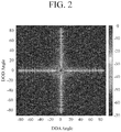
- FIG. 2 is a diagram illustrating an example of a bidirectional beam pattern in the radar device 1.
- the bidirectional beam pattern can be represented by a two-dimensional map defined by a direction cosine u T corresponding to a DOD angle and a direction cosine u R corresponding to a DOA angle.
- a conventional MIMO beam pattern has a characteristic that a DOD angle and a DOA angle are the same, and has a characteristic on the diagonal line extending from the lower left side to the upper right side in FIG. 2 .
- the bidirectional beam pattern in the radar device 1 can capture a side lobe level under a condition that a DOD angle and a DOA angle are different from each other, not clarified only by the conventional MIMO beam pattern.
- a side lobe level around a main beam area indicated in the center of FIG. 2 is higher than a side lobe level in the conventional MIMO beam pattern.
- a direction cosine u T corresponding to a DOD angle can be represented by the following formula (9)
- a direction cosine u R corresponding to a DOA angle can be represented by the following formula (10).
- ⁇ u T is an offset angle of a DOD angle based on a beam directivity angle uo
- ⁇ u R is an offset angle of a DOA angle based on the beam directivity angle u 0 .
- the MIMO steering vector a(u T ,u R ) can be represented by the following formula (13). As illustrated in the following formula (13), a(u T ,u R ) is determined as a matrix product of a matrix D(u 0 ) determined by a steering vector based on a beam directivity angle uo and a MIMO steering vector a( ⁇ u T , ⁇ u R ) based on offset angles ⁇ u T and ⁇ u R .
- FIG. 3A is a block diagram illustrating a hardware configuration for implementing a function of the radar device 1.
- FIG. 3B is a block diagram illustrating a hardware configuration for executing software for implementing the function of the radar device 1.
- a transmission device 100 includes the transmission antennas 2-1 to 2-N and the transmission signal generating units 3-1 to 3-N illustrated in FIG. 1 .
- a Reception device 101 includes the reception antennas 4-1 to 4-M and the matched filter banks 5-1 to 5-M illustrated in FIG. 1 .
- Each of functions of the correlation matrix calculating unit 6, the diagonal load processing unit 7, the window function calculating unit 8, the window function applying unit 9, and the beam forming unit 10 in the radar device 1 is implemented by a processing circuit.
- the radar device 1 includes a processing circuit for executing processes in steps ST1 to ST5 described later with reference to FIG. 4 .
- the processing circuit may be dedicated hardware or a central processing unit (CPU) for executing a program stored in a memory.
- CPU central processing unit
- the processing circuit is a processing circuit 102 of dedicated hardware illustrated in FIG. 3A , for example, a single circuit, a composite circuit, a programmed processor, a parallel programmed processor, an application specific integrated circuit (ASIC), a field-programmable gate array (FPGA), or a combination thereof corresponds to the processing circuit 102.
- the functions of the correlation matrix calculating unit 6, the diagonal load processing unit 7, the window function calculating unit 8, the window function applying unit 9, and the beam forming unit 10 may be implemented by separate processing circuits, respectively, or may be collectively implemented by a single processing circuit.
- each of the functions of the correlation matrix calculating unit 6, the diagonal load processing unit 7, the window function calculating unit 8, the window function applying unit 9, and the beam forming unit 10 is implemented by software, firmware, or a combination of software and firmware.
- the software or the firmware is described as a program and stored in a memory 104.
- the processor 103 reads and executes a program stored in the memory 104, and thereby implements each of the functions of the correlation matrix calculating unit 6, the diagonal load processing unit 7, the window function calculating unit 8, the window function applying unit 9, and the beam forming unit 10. That is, the radar device 1 includes the memory 104 for storing a program that causes processes in steps ST1 to ST5 illustrated in FIG. 4 to be executed as a result when the program is executed by the processor 103.
- the program causes a computer to execute procedures or methods of the correlation matrix calculating unit 6, the diagonal load processing unit 7, the window function calculating unit 8, the window function applying unit 9, and the beam forming unit 10.
- the memory 104 may be a computer-readable storage medium storing a program for causing a computer to function as the correlation matrix calculating unit 6, the diagonal load processing unit 7, the window function calculating unit 8, the window function applying unit 9, and the beam forming unit 10.
- a nonvolatile or volatile semiconductor memory such as random access memory (RAM), read only memory (ROM), a flash memory, erasable programmable read only memory (EPROM), or electrically-EPROM (EEPROM); a magnetic disk, a flexible disk, an optical disc, a compact disc, a mini disc, a digital versatile disk (DVD), or the like corresponds.
- RAM random access memory
- ROM read only memory
- EPROM erasable programmable read only memory
- EEPROM electrically-EPROM
- a magnetic disk a flexible disk, an optical disc, a compact disc, a mini disc, a digital versatile disk (DVD), or the like corresponds.
- Some of the functions of the correlation matrix calculating unit 6, the diagonal load processing unit 7, the window function calculating unit 8, the window function applying unit 9, and the beam forming unit 10 may be implemented by dedicated hardware, and some of the functions may be implemented by software or firmware.
- the functions of the correlation matrix calculating unit 6, the diagonal load processing unit 7, and the window function calculating unit 8 are implemented by a processing circuit as dedicated hardware.
- the functions of the window function applying unit 9 and the beam forming unit 10 may be implemented by causing the processor 103 to read and execute a program stored in the memory 104.
- the processing circuit can implement each pf the above functions by hardware, software, firmware, or a combination thereof.
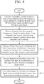
- FIG. 4 is a flowchart illustrating operation of the radar device 1, and illustrates a series of processes until a signal processing unit of the radar device 1 obtains a MIMO radar output.
- the correlation matrix calculating unit 6 calculates an unnecessary signal correlation matrix Rc using a steering vector of an unnecessary signal defined on the basis of a DOD angle of the unnecessary signal and a DOA angle of the unnecessary signal (step ST1). For example, the correlation matrix calculating unit 6 determines an area where achievement of reduction of side lobes is desired from a bidirectional beam pattern without consideration of a window function, illustrated in FIG. 2 .
- FIG. 5 is a diagram illustrating an example of an area where achievement of reduction of side lobes is desired in a bidirectional beam pattern.
- FIG. 6 is a diagram illustrating another example of the area where achievement of reduction of side lobes is desired in the bidirectional beam pattern.
- a gray area present around a main beam area a including a beam directing direction is an area where achievement of reduction of side lobes is desired.
- the area where achievement of reduction of side lobes is desired is an area having an arbitrary shape.
- an area b is a main beam area including a beam directing direction.
- the gray area in FIG. 6 corresponds to propagation in which a DOD angle falls within a main beam and a DOA angle falls within a side lobe, or propagation in which the DOD angle falls within the side lobe and the DOA angle falls within the main beam.
- This area will be referred to as an MS/SM propagation side lobe area.
- MS is an abbreviation of Mainbeam-to-Sidelobe
- SM is an abbreviation of Sidelobe-to-Mainbeam.
- b T , b R , U T , and U R are parameters that determine a region of a DOD angle of an unnecessary signal and a DOA angle of the unnecessary signal in the MS/SM propagation side lobe area.
- an unnecessary signal correlation matrix Rc can be represented by the following formula (14). Note that average power of an unnecessary signal is assumed to be unit power without loss of generality.
- R c ⁇ ⁇ U R ⁇ 0.5 b R ⁇ ⁇ 0.5 b T + 0.5 b T a ⁇ u T , ⁇ u R a H ⁇ u T , ⁇ u R d ⁇ u T d ⁇ u R + ⁇ + 0.5 b R + U R ⁇ ⁇ 0.5 b T + 0.5 b T a ⁇ u T , ⁇ u R a H ⁇ u T , ⁇ u R d ⁇ u T d ⁇ u R + ⁇ ⁇ 0.5 b R + 0.5 b R ⁇ ⁇ U T ⁇ 0.5 b T a ⁇ u T , ⁇ u R a H ⁇ u T , ⁇ u R d ⁇ u T d ⁇ u R + ⁇ ⁇ 0.5 b R + 0.5 b R ⁇ + U T a ⁇ u T , ⁇ u R a H
- the unnecessary signal correlation matrix Rc clearly has a low rank structure. That is, the area where achievement of reduction of side lobes is desired constitutes a subspace of a space where a MIMO steering vector is present.
- the diagonal load processing unit 7 performs diagonal load processing on the unnecessary signal correlation matrix Rc using a diagonal load amount ⁇ , and calculates an unnecessary signal correlation matrix R after the diagonal load processing (step ST2). For example, the diagonal load processing unit 7 determines the unnecessary signal correlation matrix R after the diagonal load processing by adding the diagonal load amount ⁇ to the unnecessary signal correlation matrix Rc according to the following formula (15).
- the diagonal load amount ⁇ virtually models a receiver noise matrix, and average power of an unnecessary signal is assumed to be unit power. Therefore, the diagonal load amount ⁇ is set so as to satisfy 0 ⁇ ⁇ ⁇ 1.
- I is a unit matrix.
- R Rc + ⁇ I
- the window function calculating unit 8 calculates a window function for obtaining a side lobe characteristic that reduces unnecessary signals on the basis of the unnecessary signal correlation matrix R after the diagonal load processing (step ST3). For example, the window function calculating unit 8 determines the window function for obtaining a side lobe characteristic that reduces unnecessary signals according to the following formula (16).
- l is a vector whose vector elements are all 1.
- R -1 l is a vector based on a value of the window function
- the transmission antennas 2-1 to 2-N transmit transmission signals generated by the transmission signal generating units 3-1 to 3-N, respectively.
- the transmission signals transmitted from the transmission antennas 2-1 to 2-N hit an object, and reflection waves thereof are received by the M reception antennas 4-1 to 4-M.
- a reception signal received by each of the reception antennas 4-1 to 4-M includes a mixture of reflection waves derived from N transmission signals.
- Each of the matched filter banks 5-1 to 5-M separates a reception signal into N reflection wave reception signals using N transmission signals generated by the transmission signal generating units 3-1 to 3-N, respectively, as a replica of a matched filter.
- reception signal vector x A vector including these M ⁇ N reception signals as vector elements is referred to as a reception signal vector x.
- the window function applying unit 9 multiplies a reception signal vector x input from the matched filter banks 5-1 to 5-M by a window function calculated by the window function calculating unit 8, and outputs a reception signal vector to which the window function is applied (step ST4).
- the window function applying unit 9 obtains a reception signal vector Twx after application of the window function by multiplying the reception signal vector x by a diagonal matrix Tw having a value of the window function as a diagonal component.
- the beam forming unit 10 forms a MIMO beam on the basis of the reception signal vector Twx input from the window function applying unit 9 and a beam directivity angle u 0 (step ST5).
- the beam forming unit 10 performs beam forming on the reception signal vector T W x after application of the window function on the basis of the following formula (17) using a beam weight a(u 0 ,u 0 ) for the beam directivity angle u 0 , and obtains a MIMO beam output y.
- y a u 0 u 0 H Twx
- the correlation matrix calculating unit 6 calculates an unnecessary signal correlation matrix Rc using a steering vector of an unnecessary signal defined on the basis of a DOD angle of the unnecessary signal and a DOA angle of the unnecessary signal.
- the correlation matrix calculating unit 6 defines a steering vector of an unnecessary signal on the basis of a DOD angle and a DOA angle of the unnecessary signal in an MS/SM propagation side lobe area, and calculates the unnecessary signal correlation matrix Rc.
- the diagonal load processing unit 7 performs diagonal load processing on the unnecessary signal correlation matrix Rc.
- the window function calculating unit 8 calculates a window function for obtaining a side lobe characteristic that reduces unnecessary signals on the basis of the unnecessary signal correlation matrix R after the diagonal load processing.
- the window function applying unit 9 applies the window function to the reception signal vector input from the matched filter banks 5-1 to 5-M.
- the beam forming unit 10 forms a MIMO beam on the basis of the reception signal vector to which the window function is applied and a beam directivity angle.
- the window function is derived on the basis of a principle of suppressing reflection signals (unnecessary signals) belonging to a subspace of a space defined by steering vectors of direct propagation clutters and multipath clutters.
- the radar device 1 can reduce direct propagation clutters and multipath clutters included in a reception signal.
- the radar device can reduce direct propagation clutters and multipath clutters included in a reception signal, and therefore can be used for various radar devices.
- 1 Radar device, 2-1 to 2-N: Transmission antenna, 3-1 to 3-N: Transmission signal generating unit, 4-1 to 4-M: Reception antenna, 5-1 to 5-M: Matched filter bank, 6: Correlation matrix calculating unit, 7: Diagonal load processing unit, 8: Window function calculating unit, 9: Window function applying unit, 10: Beam forming unit, 100: Transmission device, 101: Reception device, 102: Processing circuit, 103: Processor, 104: Memory
Landscapes
- Engineering & Computer Science (AREA)
- Radar, Positioning & Navigation (AREA)
- Remote Sensing (AREA)
- Computer Networks & Wireless Communication (AREA)
- Physics & Mathematics (AREA)
- General Physics & Mathematics (AREA)
- Signal Processing (AREA)
- Radar Systems Or Details Thereof (AREA)
Abstract
Description
- The present invention relates to a multiple input multiple output (hereinafter, referred to as MIMO) radar device.
- Conventionally, there has been known a technique in which a plurality of transmission antennas transmit transmission signals different from each other, receive reflection signals formed by reflection of the transmission signals off an object, and thereby forms a MIMO beam. Note that formation of the MIMO beam corresponds to formation of a transmission beam and formation of a reception beam with respect to a reception signal.
- A MIMO beam pattern obtained by forming the MIMO beam matches a transmission/reception product beam that is a product of a transmission beam pattern from a transmission antenna and a reception beam pattern from a reception antenna. In a conventional MIMO beam pattern, a transmission angle of a reflection signal (hereinafter, referred to as DOD angle) and an arrival angle of the reflection signal (hereinafter, referred to as DOA angle) are the same as each other, and it is assumed that the reflection signal is a directly propagated reflection signal.
- For example,
Patent Literature 1 describes a method for reducing side lobes of a MIMO beam pattern using a window function in order to reduce unnecessary reflection signals due to direct propagation (hereinafter, referred to as direct propagation clutters) included in a reception signal of a MIMO radar device. - Patent Literature 1:
JP 2016-90432 A - A reception signal of an actual MIMO radar device also includes an unnecessary reflection signal due to multipath propagation (hereinafter, referred to as multipath clutter) in addition to the direct propagation clutter.
- However, the radar device described in
Patent Literature 1 cannot reduce multipath clutters included in a reception signal disadvantageously because the multipath clutters are not considered. - The present invention solves the above problem, and an object of the present invention is to provide a radar device capable of reducing direct propagation clutters and multipath clutters included in a reception signal.
- A radar device according to the present invention includes N transmission signal generating units, wherein N indicates two or more, N transmission antennas, M reception antennas, wherein M indicates two or more, M matched filter banks, a correlation matrix calculating unit, a diagonal load processing. unit, a window function calculating unit, a window function applying unit, and a beam forming unit. The N transmission signal generating units generate transmission signals different from each other. The N transmission antennas are connected to the N transmission signal generating units one by one, and transmit transmission signals. The M reception antennas receive reflection waves of the transmission signals transmitted from the N transmission antennas, the reflection waves being formed by reflection off an object. The M matched filter banks are connected to the M reception antennas one by one, and each output a reception signal vector that is an output of a matched filter using the transmission signal generated by each of the N transmission signal generating units as a replica of the matched filter. The correlation matrix calculating unit calculates an unnecessary signal correlation matrix using a steering vector of an unnecessary signal defined on the basis of a DOD angle of the unnecessary signal and a DOA angle of the unnecessary signal. The diagonal load processing unit performs diagonal load processing on the unnecessary signal correlation matrix calculated by the correlation matrix calculating unit using a diagonal load amount, and calculates an unnecessary signal correlation matrix after the diagonal load processing. The window function calculating unit calculates a window function for obtaining a side lobe characteristic that reduces unnecessary signals on the basis of the unnecessary signal correlation matrix after the diagonal load processing, calculated by the diagonal load processing unit. The window function applying unit multiplies the reception signal vector output from the M matched filter banks by the window function calculated by the window function calculating unit, and outputs a reception signal vector to which the window function is applied. The beam forming unit forms a MIMO beam on the basis of the reception signal vector output from the window function applying unit and a beam directivity angle.
- According to the present invention, a window function is derived on the basis of a principle of suppressing reflection signals belonging to a subspace of a space defined by steering vectors of direct propagation clutters and multipath clutters to be reduced. By using this window function, the radar device can reduce direct propagation clutters and multipath clutters included in a reception signal.
-
-
FIG. 1 is a block diagram illustrating a configuration of a radar device according to a first embodiment of the present invention. -
FIG. 2 is a diagram illustrating an example of a bidirectional beam pattern in the radar device according to the first embodiment. -
FIG. 3A is a block diagram illustrating a hardware configuration for implementing a function of the radar device according to the first embodiment. -
FIG. 3B is a block diagram illustrating a hardware configuration for executing software for implementing the function of the radar device according to the first embodiment. -
FIG. 4 is a flowchart illustrating operation of the radar device according to the first embodiment. -
FIG. 5 is a diagram illustrating an example of an area where achievement of reduction of side lobes is desired in a bidirectional beam pattern. -
FIG. 6 is a diagram illustrating another example of the area where achievement of reduction of side lobes is desired in the bidirectional beam pattern. - Hereinafter, in order to describe the present invention in more detail, an embodiment for carrying out the present invention will be described with reference to the attached drawings.
-
FIG. 1 is a block diagram illustrating a configuration of aradar device 1 according to a first embodiment of the present invention. Theradar device 1 is a MIMO radar device, and includes a transmitting system, a receiving system, and a signal processing unit. The transmitting system includes N transmission antennas 2-1 to 2-N where N indicates two or more and N transmission signal generating units 3-1 to 3-N, and the receiving system includes M reception antennas 4-1 to 4-M where M indicates two or more and M matched filter banks 5-1 to 5-M. The signal processing unit includes a correlation matrix calculating unit 6, a diagonalload processing unit 7, a windowfunction calculating unit 8, a window function applying unit 9, and abeam forming unit 10. - As illustrated in
FIG. 1 , the transmission signal generating units 3-1 to 3-N are connected to the N transmission antennas 2-1 to 2-N one by one. The transmission signal generating units 3-1 to 3-N generate transmission signals different from each other. These transmission signals are separated by each of the M matched filter banks 5-1 to 5-M, and therefore are desirably orthogonal to each other. - The transmission antennas 2-1 to 2-N transmit transmission signals generated by the transmission signal generating units 3-1 to 3-N, respectively. Each of the transmission signal generating units 3-1 to 3-N is also connected to each of the M matched filter banks 5-1 to 5-M. N transmission signals generated by the N transmission signal generating units 3-1 to 3-N are output to each of the matched filter banks 5-1 to 5-M.
- As illustrated in
FIG. 1 , the matched filter bank 5-1 to 5-M are connected to the reception antennas 4-1 to 4-M one by one. The reception antennas 4-1 to 4-M receive reflection waves of transmission signals transmitted from the N transmission antennas 2-1 to 2-N, and output the reflection waves to the matched filter banks 5-1 to 5-M. The reflection waves of transmission signals are reflection waves propagated toward theradar device 1 by reflection of transmission signals transmitted from the transmission antennas 2-1 to 2-N off an object present outside theradar device 1. - Each of the M matched filter banks 5-1 to 5-M outputs a reception signal vector that is an output of a matched filter using N transmission signals generated by the N transmission signal generating units 3-1 to 3-N, respectively, as a replica of the matched filter.
- A reception signal received by each of the reception antennas 4-1 to 4-M includes a mixture of reflection waves derived from N transmission signals. Each of the matched filter banks 5-1 to 5-M separates a reception signal into N reflection wave reception signals. In this separation process, a matched filter is used. Each of the matched filter banks 5-1 to 5-M uses N transmission signals generated by the transmission signal generating units 3-1 to 3-N, respectively, as a replica of a matched filter. Since a reception signal received by one matched filter bank is separated into N reflection wave reception signals, M × N reception signals are obtained by the matched filter banks 5-1 to 5-M.
- The correlation matrix calculating unit 6 calculates an unnecessary signal correlation matrix Rc using a steering vector of an unnecessary signal defined on the basis of a DOD angle of the unnecessary signal and a DOA angle of the unnecessary signal.
- For example, the correlation matrix calculating unit 6 determines an area where achievement of reduction of side lobes is desired from a bidirectional beam pattern described later with reference to
FIG. 2 . The correlation matrix calculating unit 6 determines a steering vector of an unnecessary signal corresponding to the determined area by setting a DOD angle belonging to the determined area as a DOD angle of an unnecessary signal and setting a DOA angle belonging to the determined area as a DOA angle of the unnecessary signal. After determining all the steering vectors of unnecessary signals corresponding to the determined area, the correlation matrix calculating unit 6 calculates an unnecessary signal correlation matrix Rc using the determined steering vectors. - The diagonal
load processing unit 7 performs diagonal load processing on the unnecessary signal correlation matrix Rc calculated by the correlation matrix calculating unit 6 using a diagonal load amount ε, and calculates an unnecessary signal correlation matrix R after the diagonal load processing. For example, the diagonalload processing unit 7 calculates the unnecessary signal correlation matrix R by adding a diagonal load amount ε to the unnecessary signal correlation matrix Rc. - The window
function calculating unit 8 calculates a window function for obtaining a side lobe characteristic that reduces unnecessary signals on the basis of the unnecessary signal correlation matrix R after the diagonal load processing, input by the diagonalload processing unit 7. For example, the windowfunction calculating unit 8 determines a vector corresponding to a value of the window function from the unnecessary signal correlation matrix R, and calculates a diagonal matrix Tw having the value of the window function as a diagonal component. - The window function applying unit 9 multiplies a reception signal vector input from the M matched filter banks 5-1 to 5-M by the window function calculated by the window
function calculating unit 8, and outputs a reception signal vector to which the window function is applied. For example, the window function applying unit 9 applies the window function to a reception signal vector by determining Twx obtained by multiplying the reception signal vector by a diagonal matrix Tw. - The
beam forming unit 10 forms a MIMO beam on the basis of the reception signal vector input from the window function applying unit 9 and a beam directivity angle. For example, thebeam forming unit 10 obtains a MIMO beam output by performing MIMO beam forming on a reception signal vector using a beam weight for a beam directivity angle. - Next, a bidirectional beam pattern in the
radar device 1 which is a MIMO radar device will be described. A steering vector in theradar device 1 is represented by the following formula (1). - Hereinafter, the steering vector in the
radar device 1 is referred to as a MIMO steering vector a(uT,uR). In the following formula (1), aT(uT) is a transmission steering vector, and uT is a direction cosine corresponding to a DOD angle. aR(uR) is a reception steering vector, and uR is a direction cosine corresponding to a DOA angle.
- Without loss of generality, in a case where a beam directivity angle uo in a MIMO radar device is set to a boresight direction (u0 = 0), a MIMO beam weight w0 can be determined by the following formula (2).

- In order to achieve reduction of side lobes in a transmission beam pattern and a reception beam pattern, for example, when a diagonal matrix having a value of a window function such as a Hamming window as a diagonal component is represented by TT or TR, the MIMO beam weight wo is determined by the following formula (3).

- AMIMO beam response y(uT,uR) is calculated by the following formula (4). Note that α determined by the following formula (5) is a normalization coefficient for keeping a white noise gain constant. A transmission beam response yT(uT) in the following formula (4) is determined by the following formula (6), and a reception beam response yR(uR) in the following formula (4) is determined by the following formula (7).


- A bidirectional beam pattern B(uT,uR) in the
radar device 1 is determined by the following formula (8). As illustrated in the following formula (8), the bidirectional beam pattern B(uT,uR) can be decomposed into a transmission beam pattern |yT(uT)|2 and a reception beam pattern |yR(uR)|2, and the bidirectional beam pattern B(uT,uR) is represented by a product of the beam patterns. - Since uT and uR are independent variables independent of each other, the bidirectional beam pattern B(uT,uR) is evaluated in a two-dimensional map defined by uT and uR.


-
FIG. 2 is a diagram illustrating an example of a bidirectional beam pattern in theradar device 1. As illustrated inFIG. 2 , the bidirectional beam pattern can be represented by a two-dimensional map defined by a direction cosine uT corresponding to a DOD angle and a direction cosine uR corresponding to a DOA angle. A conventional MIMO beam pattern has a characteristic that a DOD angle and a DOA angle are the same, and has a characteristic on the diagonal line extending from the lower left side to the upper right side inFIG. 2 . - On the other hand, the bidirectional beam pattern in the
radar device 1 can capture a side lobe level under a condition that a DOD angle and a DOA angle are different from each other, not clarified only by the conventional MIMO beam pattern. In particular, a side lobe level around a main beam area indicated in the center ofFIG. 2 is higher than a side lobe level in the conventional MIMO beam pattern. - Next, the MIMO steering vector will be described.
- When a beam directivity angle in the
radar device 1 is represented by u0, a direction cosine uT corresponding to a DOD angle can be represented by the following formula (9), and a direction cosine uR corresponding to a DOA angle can be represented by the following formula (10). In the following formulas (9) and (10), ΔuT is an offset angle of a DOD angle based on a beam directivity angle uo, and ΔuR is an offset angle of a DOA angle based on the beam directivity angle u0.

- A transmission steering vector aT(uT) can be represented by the following formula (11), and a reception steering vector aR(uR) can be represented by the following formula (12). Note that in the following formulas (11) and (12), DT(u0) = diag{aT(u0)} and DR(u0) = diag{aR(u0)} are satisfied.
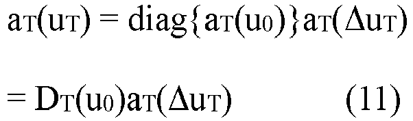

- As a result, the MIMO steering vector a(uT,uR) can be represented by the following formula (13). As illustrated in the following formula (13), a(uT,uR) is determined as a matrix product of a matrix D(u0) determined by a steering vector based on a beam directivity angle uo and a MIMO steering vector a(ΔuT,ΔuR) based on offset angles ΔuT and ΔuR.


-
FIG. 3A is a block diagram illustrating a hardware configuration for implementing a function of theradar device 1.FIG. 3B is a block diagram illustrating a hardware configuration for executing software for implementing the function of theradar device 1. InFIGS. 3A and 3B , atransmission device 100 includes the transmission antennas 2-1 to 2-N and the transmission signal generating units 3-1 to 3-N illustrated inFIG. 1 . AReception device 101 includes the reception antennas 4-1 to 4-M and the matched filter banks 5-1 to 5-M illustrated inFIG. 1 . - Each of functions of the correlation matrix calculating unit 6, the diagonal
load processing unit 7, the windowfunction calculating unit 8, the window function applying unit 9, and thebeam forming unit 10 in theradar device 1 is implemented by a processing circuit. - That is, the
radar device 1 includes a processing circuit for executing processes in steps ST1 to ST5 described later with reference toFIG. 4 . - The processing circuit may be dedicated hardware or a central processing unit (CPU) for executing a program stored in a memory.
- In a case where the processing circuit is a
processing circuit 102 of dedicated hardware illustrated inFIG. 3A , for example, a single circuit, a composite circuit, a programmed processor, a parallel programmed processor, an application specific integrated circuit (ASIC), a field-programmable gate array (FPGA), or a combination thereof corresponds to theprocessing circuit 102. The functions of the correlation matrix calculating unit 6, the diagonalload processing unit 7, the windowfunction calculating unit 8, the window function applying unit 9, and thebeam forming unit 10 may be implemented by separate processing circuits, respectively, or may be collectively implemented by a single processing circuit. - In a case where the processing circuit is a
processor 103 illustrated inFIG. 3B , each of the functions of the correlation matrix calculating unit 6, the diagonalload processing unit 7, the windowfunction calculating unit 8, the window function applying unit 9, and thebeam forming unit 10 is implemented by software, firmware, or a combination of software and firmware. The software or the firmware is described as a program and stored in amemory 104. - The
processor 103 reads and executes a program stored in thememory 104, and thereby implements each of the functions of the correlation matrix calculating unit 6, the diagonalload processing unit 7, the windowfunction calculating unit 8, the window function applying unit 9, and thebeam forming unit 10. That is, theradar device 1 includes thememory 104 for storing a program that causes processes in steps ST1 to ST5 illustrated inFIG. 4 to be executed as a result when the program is executed by theprocessor 103. - The program causes a computer to execute procedures or methods of the correlation matrix calculating unit 6, the diagonal
load processing unit 7, the windowfunction calculating unit 8, the window function applying unit 9, and thebeam forming unit 10. Thememory 104 may be a computer-readable storage medium storing a program for causing a computer to function as the correlation matrix calculating unit 6, the diagonalload processing unit 7, the windowfunction calculating unit 8, the window function applying unit 9, and thebeam forming unit 10. - To the
memory 104, for example, a nonvolatile or volatile semiconductor memory such as random access memory (RAM), read only memory (ROM), a flash memory, erasable programmable read only memory (EPROM), or electrically-EPROM (EEPROM); a magnetic disk, a flexible disk, an optical disc, a compact disc, a mini disc, a digital versatile disk (DVD), or the like corresponds. - Some of the functions of the correlation matrix calculating unit 6, the diagonal
load processing unit 7, the windowfunction calculating unit 8, the window function applying unit 9, and thebeam forming unit 10 may be implemented by dedicated hardware, and some of the functions may be implemented by software or firmware. For example, the functions of the correlation matrix calculating unit 6, the diagonalload processing unit 7, and the windowfunction calculating unit 8 are implemented by a processing circuit as dedicated hardware. The functions of the window function applying unit 9 and thebeam forming unit 10 may be implemented by causing theprocessor 103 to read and execute a program stored in thememory 104. As described above, the processing circuit can implement each pf the above functions by hardware, software, firmware, or a combination thereof. - Next, the operation will be described.
-
FIG. 4 is a flowchart illustrating operation of theradar device 1, and illustrates a series of processes until a signal processing unit of theradar device 1 obtains a MIMO radar output. - The correlation matrix calculating unit 6 calculates an unnecessary signal correlation matrix Rc using a steering vector of an unnecessary signal defined on the basis of a DOD angle of the unnecessary signal and a DOA angle of the unnecessary signal (step ST1). For example, the correlation matrix calculating unit 6 determines an area where achievement of reduction of side lobes is desired from a bidirectional beam pattern without consideration of a window function, illustrated in
FIG. 2 . -
FIG. 5 is a diagram illustrating an example of an area where achievement of reduction of side lobes is desired in a bidirectional beam pattern.FIG. 6 is a diagram illustrating another example of the area where achievement of reduction of side lobes is desired in the bidirectional beam pattern. InFIG. 5 , a gray area present around a main beam area a including a beam directing direction is an area where achievement of reduction of side lobes is desired. As described above, the area where achievement of reduction of side lobes is desired is an area having an arbitrary shape. - Therefore, for simplicity of description, a case where the area where achievement of reduction of side lobes is desired is determined as the gray area in
FIG. 6 will be described as an example. Note that an area b is a main beam area including a beam directing direction. The gray area inFIG. 6 corresponds to propagation in which a DOD angle falls within a main beam and a DOA angle falls within a side lobe, or propagation in which the DOD angle falls within the side lobe and the DOA angle falls within the main beam. This area will be referred to as an MS/SM propagation side lobe area. MS is an abbreviation of Mainbeam-to-Sidelobe, and SM is an abbreviation of Sidelobe-to-Mainbeam. - In
FIG. 6 , bT, bR, UT, and UR are parameters that determine a region of a DOD angle of an unnecessary signal and a DOA angle of the unnecessary signal in the MS/SM propagation side lobe area. At this time, an unnecessary signal correlation matrix Rc can be represented by the following formula (14). Note that average power of an unnecessary signal is assumed to be unit power without loss of generality.
- Since the area where achievement of reduction of side lobes is desired is a part of an angle region defined by a DOD angle and a DOA angle as illustrated in
FIG. 5 or 6 , the unnecessary signal correlation matrix Rc clearly has a low rank structure. That is, the area where achievement of reduction of side lobes is desired constitutes a subspace of a space where a MIMO steering vector is present. - Return to the description of
FIG. 4 . The diagonalload processing unit 7 performs diagonal load processing on the unnecessary signal correlation matrix Rc using a diagonal load amount ε, and calculates an unnecessary signal correlation matrix R after the diagonal load processing (step ST2). For example, the diagonalload processing unit 7 determines the unnecessary signal correlation matrix R after the diagonal load processing by adding the diagonal load amount ε to the unnecessary signal correlation matrix Rc according to the following formula (15). The diagonal load amount ε virtually models a receiver noise matrix, and average power of an unnecessary signal is assumed to be unit power. Therefore, the diagonal load amount ε is set so as to satisfy 0 < ε << 1. In the following formula (15), I is a unit matrix.
- The window
function calculating unit 8 calculates a window function for obtaining a side lobe characteristic that reduces unnecessary signals on the basis of the unnecessary signal correlation matrix R after the diagonal load processing (step ST3). For example, the windowfunction calculating unit 8 determines the window function for obtaining a side lobe characteristic that reduces unnecessary signals according to the following formula (16). Here, l is a vector whose vector elements are all 1. R-1l is a vector based on a value of the window function, and Tw is a diagonal matrix having the value of the window function as a diagonal component.
- The transmission antennas 2-1 to 2-N transmit transmission signals generated by the transmission signal generating units 3-1 to 3-N, respectively. The transmission signals transmitted from the transmission antennas 2-1 to 2-N hit an object, and reflection waves thereof are received by the M reception antennas 4-1 to 4-M.
- A reception signal received by each of the reception antennas 4-1 to 4-M includes a mixture of reflection waves derived from N transmission signals. Each of the matched filter banks 5-1 to 5-M separates a reception signal into N reflection wave reception signals using N transmission signals generated by the transmission signal generating units 3-1 to 3-N, respectively, as a replica of a matched filter.
- As described above, since a reception signal received by one matched filter bank is separated into N reflection wave reception signals, M × N reception signals are obtained by the matched filter banks 5-1 to 5-M. A vector including these M × N reception signals as vector elements is referred to as a reception signal vector x.
- The window function applying unit 9 multiplies a reception signal vector x input from the matched filter banks 5-1 to 5-M by a window function calculated by the window
function calculating unit 8, and outputs a reception signal vector to which the window function is applied (step ST4). For example, the window function applying unit 9 obtains a reception signal vector Twx after application of the window function by multiplying the reception signal vector x by a diagonal matrix Tw having a value of the window function as a diagonal component. - The
beam forming unit 10 forms a MIMO beam on the basis of the reception signal vector Twx input from the window function applying unit 9 and a beam directivity angle u0 (step ST5). For example, thebeam forming unit 10 performs beam forming on the reception signal vector TWx after application of the window function on the basis of the following formula (17) using a beam weight a(u0,u0) for the beam directivity angle u0, and obtains a MIMO beam output y.
- As described above, in the
radar device 1 according to the first embodiment, the correlation matrix calculating unit 6 calculates an unnecessary signal correlation matrix Rc using a steering vector of an unnecessary signal defined on the basis of a DOD angle of the unnecessary signal and a DOA angle of the unnecessary signal. In particular, the correlation matrix calculating unit 6 defines a steering vector of an unnecessary signal on the basis of a DOD angle and a DOA angle of the unnecessary signal in an MS/SM propagation side lobe area, and calculates the unnecessary signal correlation matrix Rc. The diagonalload processing unit 7 performs diagonal load processing on the unnecessary signal correlation matrix Rc. The windowfunction calculating unit 8 calculates a window function for obtaining a side lobe characteristic that reduces unnecessary signals on the basis of the unnecessary signal correlation matrix R after the diagonal load processing. The window function applying unit 9 applies the window function to the reception signal vector input from the matched filter banks 5-1 to 5-M. Thebeam forming unit 10 forms a MIMO beam on the basis of the reception signal vector to which the window function is applied and a beam directivity angle. - As a result, the window function is derived on the basis of a principle of suppressing reflection signals (unnecessary signals) belonging to a subspace of a space defined by steering vectors of direct propagation clutters and multipath clutters. By using this window function, the
radar device 1 can reduce direct propagation clutters and multipath clutters included in a reception signal. - Note that the present invention is not limited to the above embodiment, and any component in the embodiment can be modified, or any component in the embodiment can be omitted within the scope of the present invention.
- The radar device according to the present invention can reduce direct propagation clutters and multipath clutters included in a reception signal, and therefore can be used for various radar devices.
- 1: Radar device, 2-1 to 2-N: Transmission antenna, 3-1 to 3-N: Transmission signal generating unit, 4-1 to 4-M: Reception antenna, 5-1 to 5-M: Matched filter bank, 6: Correlation matrix calculating unit, 7: Diagonal load processing unit, 8: Window function calculating unit, 9: Window function applying unit, 10: Beam forming unit, 100: Transmission device, 101: Reception device, 102: Processing circuit, 103: Processor, 104: Memory
Claims (2)
- A radar device comprising:N transmission signal generating units for generating transmission signals different from each other, wherein N indicates two or more;N transmission antennas for transmitting a transmission signal by being connected to the N transmission signal generating units one by one;M reception antennas for receiving reflection waves of the transmission signals transmitted from the N transmission antennas, the reflection waves being formed by reflection off an object, wherein M indicates two or more;M matched filter banks for each outputting a reception signal vector that is an output of a matched filter using a transmission signal generated by each of the N transmission signal generating units as a replica of the matched filter by being connected to the M reception antennas one by one;a correlation matrix calculating unit for calculating an unnecessary signal correlation matrix using a steering vector of an unnecessary signal defined on a basis of a transmission angle of the unnecessary signal and an arrival angle of the unnecessary signal;a diagonal load processing unit for performing diagonal load processing on the unnecessary signal correlation matrix calculated by the correlation matrix calculating unit using a diagonal load amount, and calculating an unnecessary signal correlation matrix after the diagonal load processing;a window function calculating unit for calculating a window function for obtaining a side lobe characteristic that reduces unnecessary signals on a basis of the unnecessary signal correlation matrix after the diagonal load processing calculated by the diagonal load processing unit;a window function applying unit for multiplying the reception signal vector output from the M matched filter banks by the window function calculated by the window function calculating unit, and outputting the reception signal vector to which the window function is applied; anda beam forming unit for forming a multiple input multiple output beam on a basis of the reception signal vector output from the window function applying unit and a beam directivity angle.
- The radar device according to claim 1, wherein
the correlation matrix calculating unit defines a steering vector of an unnecessary signal on a basis of a transmission angle and an arrival angle of an unnecessary signal in a side lobe area corresponding to propagation in which the transmission angle falls within a main beam and the arrival angle falls within a side lobe, or propagation in which the transmission angle falls within the side lobe and the arrival angle falls within the main beam, and calculates an unnecessary signal correlation matrix.
Applications Claiming Priority (1)
| Application Number | Priority Date | Filing Date | Title |
|---|---|---|---|
| PCT/JP2018/004676 WO2019155625A1 (en) | 2018-02-09 | 2018-02-09 | Radar device |
Publications (3)
| Publication Number | Publication Date |
|---|---|
| EP3736598A1 true EP3736598A1 (en) | 2020-11-11 |
| EP3736598A4 EP3736598A4 (en) | 2021-01-06 |
| EP3736598B1 EP3736598B1 (en) | 2022-08-17 |
Family
ID=67549548
Family Applications (1)
| Application Number | Title | Priority Date | Filing Date |
|---|---|---|---|
| EP18904516.4A Active EP3736598B1 (en) | 2018-02-09 | 2018-02-09 | Radar device |
Country Status (5)
| Country | Link |
|---|---|
| US (1) | US11245441B2 (en) |
| EP (1) | EP3736598B1 (en) |
| JP (1) | JP6693681B2 (en) |
| CA (1) | CA3087857C (en) |
| WO (1) | WO2019155625A1 (en) |
Families Citing this family (11)
| Publication number | Priority date | Publication date | Assignee | Title |
|---|---|---|---|---|
| CN110412537A (en) * | 2019-09-05 | 2019-11-05 | 武汉亿维登科技发展有限公司 | A kind of bistatic MIMO radar angle estimating method |
| JP2021110554A (en) * | 2020-01-06 | 2021-08-02 | 株式会社東芝 | Radar device and radar signal processing method thereof |
| RU2732505C1 (en) * | 2020-01-27 | 2020-09-18 | Акционерное общество "Концерн "Созвездие" | Method for detection and azimuth direction finding of ground-based radio-frequency sources from a flight-lifting means |
| CN113156383B (en) * | 2021-04-21 | 2024-02-20 | 杭州加速科技有限公司 | Radar signal anti-interference method, system and data processing equipment based on FPGA |
| CN117795370A (en) * | 2021-08-18 | 2024-03-29 | 三菱电机株式会社 | MIMO radar signal processing device, received signal processing device, and propagation mode discrimination method focusing on received signal vectors |
| AU2021460828B2 (en) * | 2021-08-18 | 2024-05-16 | Mitsubishi Electric Corporation | Mimo radar signal processing device and reception signal processing device, and method for distinguishing propagation mode of reception signal vector of interest |
| JP7459849B2 (en) | 2021-08-24 | 2024-04-02 | 株式会社デンソー | Radar device and direction estimation method |
| JP7512979B2 (en) | 2021-08-24 | 2024-07-09 | 株式会社デンソー | Radar device and direction estimation method |
| CN115327487B (en) * | 2022-07-06 | 2024-07-09 | 西安电子科技大学 | A method for optimizing the sidelobe level of circular phased array based on generalized window function |
| CN115642941B (en) * | 2022-10-14 | 2023-08-11 | 山东大学 | Transmitting beam forming method of multi-antenna integrated system |
| US12455363B2 (en) * | 2022-12-30 | 2025-10-28 | Nextpert Inc. | Multiple-input multiple-output radar device and method for scanning at least one moving object and estimating probability of the object in 3D surrounding space |
Family Cites Families (8)
| Publication number | Priority date | Publication date | Assignee | Title |
|---|---|---|---|---|
| JPH10288659A (en) * | 1997-04-14 | 1998-10-27 | Mitsubishi Electric Corp | Interference wave suppression device |
| JP2007288659A (en) | 2006-04-19 | 2007-11-01 | Funai Electric Co Ltd | Cathode ray tube type television receiver |
| JP2011158430A (en) | 2010-02-03 | 2011-08-18 | Mitsubishi Electric Corp | Transceiver beam shaping device |
| US9207313B2 (en) * | 2013-03-11 | 2015-12-08 | Src, Inc. | MIMO angle estimation with simultaneous mainlobe jammer cancellation |
| JP6164936B2 (en) * | 2013-05-27 | 2017-07-19 | 三菱電機株式会社 | Radar equipment |
| JP6079709B2 (en) * | 2014-07-08 | 2017-02-15 | 三菱電機株式会社 | Radar equipment |
| JP6453614B2 (en) | 2014-11-06 | 2019-01-16 | 株式会社東芝 | DBF radar apparatus and radar signal processing method thereof |
| US20180166794A1 (en) * | 2016-12-14 | 2018-06-14 | GM Global Technology Operations LLC | 2d-mimo radar antenna array geometry and design method |
-
2018
- 2018-02-09 JP JP2019570258A patent/JP6693681B2/en active Active
- 2018-02-09 WO PCT/JP2018/004676 patent/WO2019155625A1/en not_active Ceased
- 2018-02-09 CA CA3087857A patent/CA3087857C/en active Active
- 2018-02-09 US US16/967,296 patent/US11245441B2/en active Active
- 2018-02-09 EP EP18904516.4A patent/EP3736598B1/en active Active
Also Published As
| Publication number | Publication date |
|---|---|
| JP6693681B2 (en) | 2020-05-13 |
| JPWO2019155625A1 (en) | 2020-06-18 |
| EP3736598A4 (en) | 2021-01-06 |
| US20210028826A1 (en) | 2021-01-28 |
| CA3087857A1 (en) | 2019-08-15 |
| US11245441B2 (en) | 2022-02-08 |
| EP3736598B1 (en) | 2022-08-17 |
| CA3087857C (en) | 2020-11-10 |
| WO2019155625A1 (en) | 2019-08-15 |
Similar Documents
| Publication | Publication Date | Title |
|---|---|---|
| EP3736598B1 (en) | Radar device | |
| EP3916427B1 (en) | Radar apparatus and method | |
| US20160172767A1 (en) | Congruent non-uniform antenna arrays | |
| US20080150794A1 (en) | Weight calculation method, weight calculation device, adaptive array antenna, and radar device | |
| KR101603630B1 (en) | Method and Apparatus for suppressing jammer signals and estimating Angle Of Arrival of original signal using orthogonal of transmitting signal waveform | |
| CN113093173A (en) | Beamforming techniques to implement Iterative Adaptive Approach (IAA) | |
| JP4972852B2 (en) | Radar equipment | |
| US9444558B1 (en) | Synthetic robust adaptive beamforming | |
| US11892558B2 (en) | Method and apparatus for estimating direction of arrival of radar reception signal using antenna array extrapolation | |
| EP2281325B1 (en) | A process for minimising jammer noise in receiver systems | |
| US12019138B2 (en) | Beam formation device, radar device, and beam formation method | |
| JP4232628B2 (en) | Radar equipment | |
| JP2007208702A (en) | Weight calculation method, weight calculation device, adaptive array antenna, and radar device | |
| CN114609581B (en) | Array super-resolution direction finding method for comparing maximum value of vector projection in scanning direction | |
| JP4879761B2 (en) | Radar equipment | |
| CN116660889A (en) | Multistatic radar system and its detection method, device and storage medium | |
| JP4250522B2 (en) | Antenna device | |
| WO2021196165A1 (en) | Frequency analysis method, device and radar | |
| JP5152949B2 (en) | Weight calculation method, weight calculation device, adaptive array antenna, and radar device | |
| CN115453503B (en) | Target detection method suitable for underwater vehicle and application thereof | |
| Shang et al. | The analysis of interference suppression capability of mvdr algorithm based on microphone array | |
| KR102208175B1 (en) | Adaptive tracking frequency control method of mobile radar | |
| KR101240415B1 (en) | Method for processing sidelobe blanking in adaptive array radar | |
| KR20200125064A (en) | Method for estimating distance between transmittier array antennas and apparatus for the same |
Legal Events
| Date | Code | Title | Description |
|---|---|---|---|
| STAA | Information on the status of an ep patent application or granted ep patent |
Free format text: STATUS: THE INTERNATIONAL PUBLICATION HAS BEEN MADE |
|
| PUAI | Public reference made under article 153(3) epc to a published international application that has entered the european phase |
Free format text: ORIGINAL CODE: 0009012 |
|
| STAA | Information on the status of an ep patent application or granted ep patent |
Free format text: STATUS: REQUEST FOR EXAMINATION WAS MADE |
|
| 17P | Request for examination filed |
Effective date: 20200803 |
|
| AK | Designated contracting states |
Kind code of ref document: A1 Designated state(s): AL AT BE BG CH CY CZ DE DK EE ES FI FR GB GR HR HU IE IS IT LI LT LU LV MC MK MT NL NO PL PT RO RS SE SI SK SM TR |
|
| AX | Request for extension of the european patent |
Extension state: BA ME |
|
| A4 | Supplementary search report drawn up and despatched |
Effective date: 20201208 |
|
| RIC1 | Information provided on ipc code assigned before grant |
Ipc: G01S 13/42 20060101ALI20201202BHEP Ipc: G01S 7/02 20060101AFI20201202BHEP |
|
| DAV | Request for validation of the european patent (deleted) | ||
| DAX | Request for extension of the european patent (deleted) | ||
| STAA | Information on the status of an ep patent application or granted ep patent |
Free format text: STATUS: EXAMINATION IS IN PROGRESS |
|
| 17Q | First examination report despatched |
Effective date: 20210922 |
|
| REG | Reference to a national code |
Ref country code: DE Ref legal event code: R079 Ref document number: 602018039554 Country of ref document: DE Free format text: PREVIOUS MAIN CLASS: G01S0007020000 Ipc: G01S0007280000 |
|
| RIC1 | Information provided on ipc code assigned before grant |
Ipc: G01S 13/42 20060101ALI20220201BHEP Ipc: G01S 7/28 20060101AFI20220201BHEP |
|
| GRAP | Despatch of communication of intention to grant a patent |
Free format text: ORIGINAL CODE: EPIDOSNIGR1 |
|
| STAA | Information on the status of an ep patent application or granted ep patent |
Free format text: STATUS: GRANT OF PATENT IS INTENDED |
|
| INTG | Intention to grant announced |
Effective date: 20220318 |
|
| GRAS | Grant fee paid |
Free format text: ORIGINAL CODE: EPIDOSNIGR3 |
|
| GRAA | (expected) grant |
Free format text: ORIGINAL CODE: 0009210 |
|
| STAA | Information on the status of an ep patent application or granted ep patent |
Free format text: STATUS: THE PATENT HAS BEEN GRANTED |
|
| AK | Designated contracting states |
Kind code of ref document: B1 Designated state(s): AL AT BE BG CH CY CZ DE DK EE ES FI FR GB GR HR HU IE IS IT LI LT LU LV MC MK MT NL NO PL PT RO RS SE SI SK SM TR |
|
| REG | Reference to a national code |
Ref country code: CH Ref legal event code: EP |
|
| REG | Reference to a national code |
Ref country code: DE Ref legal event code: R096 Ref document number: 602018039554 Country of ref document: DE |
|
| REG | Reference to a national code |
Ref country code: IE Ref legal event code: FG4D |
|
| REG | Reference to a national code |
Ref country code: AT Ref legal event code: REF Ref document number: 1512531 Country of ref document: AT Kind code of ref document: T Effective date: 20220915 |
|
| REG | Reference to a national code |
Ref country code: NL Ref legal event code: MP Effective date: 20220817 |
|
| REG | Reference to a national code |
Ref country code: LT Ref legal event code: MG9D |
|
| PG25 | Lapsed in a contracting state [announced via postgrant information from national office to epo] |
Ref country code: SE Free format text: LAPSE BECAUSE OF FAILURE TO SUBMIT A TRANSLATION OF THE DESCRIPTION OR TO PAY THE FEE WITHIN THE PRESCRIBED TIME-LIMIT Effective date: 20220817 Ref country code: RS Free format text: LAPSE BECAUSE OF FAILURE TO SUBMIT A TRANSLATION OF THE DESCRIPTION OR TO PAY THE FEE WITHIN THE PRESCRIBED TIME-LIMIT Effective date: 20220817 Ref country code: PT Free format text: LAPSE BECAUSE OF FAILURE TO SUBMIT A TRANSLATION OF THE DESCRIPTION OR TO PAY THE FEE WITHIN THE PRESCRIBED TIME-LIMIT Effective date: 20221219 Ref country code: NO Free format text: LAPSE BECAUSE OF FAILURE TO SUBMIT A TRANSLATION OF THE DESCRIPTION OR TO PAY THE FEE WITHIN THE PRESCRIBED TIME-LIMIT Effective date: 20221117 Ref country code: NL Free format text: LAPSE BECAUSE OF FAILURE TO SUBMIT A TRANSLATION OF THE DESCRIPTION OR TO PAY THE FEE WITHIN THE PRESCRIBED TIME-LIMIT Effective date: 20220817 Ref country code: LV Free format text: LAPSE BECAUSE OF FAILURE TO SUBMIT A TRANSLATION OF THE DESCRIPTION OR TO PAY THE FEE WITHIN THE PRESCRIBED TIME-LIMIT Effective date: 20220817 Ref country code: LT Free format text: LAPSE BECAUSE OF FAILURE TO SUBMIT A TRANSLATION OF THE DESCRIPTION OR TO PAY THE FEE WITHIN THE PRESCRIBED TIME-LIMIT Effective date: 20220817 Ref country code: FI Free format text: LAPSE BECAUSE OF FAILURE TO SUBMIT A TRANSLATION OF THE DESCRIPTION OR TO PAY THE FEE WITHIN THE PRESCRIBED TIME-LIMIT Effective date: 20220817 |
|
| REG | Reference to a national code |
Ref country code: AT Ref legal event code: MK05 Ref document number: 1512531 Country of ref document: AT Kind code of ref document: T Effective date: 20220817 |
|
| PG25 | Lapsed in a contracting state [announced via postgrant information from national office to epo] |
Ref country code: PL Free format text: LAPSE BECAUSE OF FAILURE TO SUBMIT A TRANSLATION OF THE DESCRIPTION OR TO PAY THE FEE WITHIN THE PRESCRIBED TIME-LIMIT Effective date: 20220817 Ref country code: IS Free format text: LAPSE BECAUSE OF FAILURE TO SUBMIT A TRANSLATION OF THE DESCRIPTION OR TO PAY THE FEE WITHIN THE PRESCRIBED TIME-LIMIT Effective date: 20221217 Ref country code: HR Free format text: LAPSE BECAUSE OF FAILURE TO SUBMIT A TRANSLATION OF THE DESCRIPTION OR TO PAY THE FEE WITHIN THE PRESCRIBED TIME-LIMIT Effective date: 20220817 Ref country code: GR Free format text: LAPSE BECAUSE OF FAILURE TO SUBMIT A TRANSLATION OF THE DESCRIPTION OR TO PAY THE FEE WITHIN THE PRESCRIBED TIME-LIMIT Effective date: 20221118 |
|
| PG25 | Lapsed in a contracting state [announced via postgrant information from national office to epo] |
Ref country code: SM Free format text: LAPSE BECAUSE OF FAILURE TO SUBMIT A TRANSLATION OF THE DESCRIPTION OR TO PAY THE FEE WITHIN THE PRESCRIBED TIME-LIMIT Effective date: 20220817 Ref country code: RO Free format text: LAPSE BECAUSE OF FAILURE TO SUBMIT A TRANSLATION OF THE DESCRIPTION OR TO PAY THE FEE WITHIN THE PRESCRIBED TIME-LIMIT Effective date: 20220817 Ref country code: ES Free format text: LAPSE BECAUSE OF FAILURE TO SUBMIT A TRANSLATION OF THE DESCRIPTION OR TO PAY THE FEE WITHIN THE PRESCRIBED TIME-LIMIT Effective date: 20220817 Ref country code: DK Free format text: LAPSE BECAUSE OF FAILURE TO SUBMIT A TRANSLATION OF THE DESCRIPTION OR TO PAY THE FEE WITHIN THE PRESCRIBED TIME-LIMIT Effective date: 20220817 Ref country code: CZ Free format text: LAPSE BECAUSE OF FAILURE TO SUBMIT A TRANSLATION OF THE DESCRIPTION OR TO PAY THE FEE WITHIN THE PRESCRIBED TIME-LIMIT Effective date: 20220817 Ref country code: AT Free format text: LAPSE BECAUSE OF FAILURE TO SUBMIT A TRANSLATION OF THE DESCRIPTION OR TO PAY THE FEE WITHIN THE PRESCRIBED TIME-LIMIT Effective date: 20220817 |
|
| REG | Reference to a national code |
Ref country code: DE Ref legal event code: R097 Ref document number: 602018039554 Country of ref document: DE |
|
| PG25 | Lapsed in a contracting state [announced via postgrant information from national office to epo] |
Ref country code: SK Free format text: LAPSE BECAUSE OF FAILURE TO SUBMIT A TRANSLATION OF THE DESCRIPTION OR TO PAY THE FEE WITHIN THE PRESCRIBED TIME-LIMIT Effective date: 20220817 Ref country code: EE Free format text: LAPSE BECAUSE OF FAILURE TO SUBMIT A TRANSLATION OF THE DESCRIPTION OR TO PAY THE FEE WITHIN THE PRESCRIBED TIME-LIMIT Effective date: 20220817 |
|
| P01 | Opt-out of the competence of the unified patent court (upc) registered |
Effective date: 20230512 |
|
| PLBE | No opposition filed within time limit |
Free format text: ORIGINAL CODE: 0009261 |
|
| STAA | Information on the status of an ep patent application or granted ep patent |
Free format text: STATUS: NO OPPOSITION FILED WITHIN TIME LIMIT |
|
| PG25 | Lapsed in a contracting state [announced via postgrant information from national office to epo] |
Ref country code: AL Free format text: LAPSE BECAUSE OF FAILURE TO SUBMIT A TRANSLATION OF THE DESCRIPTION OR TO PAY THE FEE WITHIN THE PRESCRIBED TIME-LIMIT Effective date: 20220817 |
|
| 26N | No opposition filed |
Effective date: 20230519 |
|
| PG25 | Lapsed in a contracting state [announced via postgrant information from national office to epo] |
Ref country code: SI Free format text: LAPSE BECAUSE OF FAILURE TO SUBMIT A TRANSLATION OF THE DESCRIPTION OR TO PAY THE FEE WITHIN THE PRESCRIBED TIME-LIMIT Effective date: 20220817 |
|
| PG25 | Lapsed in a contracting state [announced via postgrant information from national office to epo] |
Ref country code: MC Free format text: LAPSE BECAUSE OF FAILURE TO SUBMIT A TRANSLATION OF THE DESCRIPTION OR TO PAY THE FEE WITHIN THE PRESCRIBED TIME-LIMIT Effective date: 20220817 |
|
| REG | Reference to a national code |
Ref country code: CH Ref legal event code: PL |
|
| REG | Reference to a national code |
Ref country code: BE Ref legal event code: MM Effective date: 20230228 |
|
| PG25 | Lapsed in a contracting state [announced via postgrant information from national office to epo] |
Ref country code: LU Free format text: LAPSE BECAUSE OF NON-PAYMENT OF DUE FEES Effective date: 20230209 Ref country code: LI Free format text: LAPSE BECAUSE OF NON-PAYMENT OF DUE FEES Effective date: 20230228 Ref country code: CH Free format text: LAPSE BECAUSE OF NON-PAYMENT OF DUE FEES Effective date: 20230228 |
|
| REG | Reference to a national code |
Ref country code: IE Ref legal event code: MM4A |
|
| PG25 | Lapsed in a contracting state [announced via postgrant information from national office to epo] |
Ref country code: IE Free format text: LAPSE BECAUSE OF NON-PAYMENT OF DUE FEES Effective date: 20230209 |
|
| PG25 | Lapsed in a contracting state [announced via postgrant information from national office to epo] |
Ref country code: BE Free format text: LAPSE BECAUSE OF NON-PAYMENT OF DUE FEES Effective date: 20230228 |
|
| PG25 | Lapsed in a contracting state [announced via postgrant information from national office to epo] |
Ref country code: IT Free format text: LAPSE BECAUSE OF FAILURE TO SUBMIT A TRANSLATION OF THE DESCRIPTION OR TO PAY THE FEE WITHIN THE PRESCRIBED TIME-LIMIT Effective date: 20220817 |
|
| PG25 | Lapsed in a contracting state [announced via postgrant information from national office to epo] |
Ref country code: BG Free format text: LAPSE BECAUSE OF FAILURE TO SUBMIT A TRANSLATION OF THE DESCRIPTION OR TO PAY THE FEE WITHIN THE PRESCRIBED TIME-LIMIT Effective date: 20220817 |
|
| PG25 | Lapsed in a contracting state [announced via postgrant information from national office to epo] |
Ref country code: BG Free format text: LAPSE BECAUSE OF FAILURE TO SUBMIT A TRANSLATION OF THE DESCRIPTION OR TO PAY THE FEE WITHIN THE PRESCRIBED TIME-LIMIT Effective date: 20220817 |
|
| REG | Reference to a national code |
Ref country code: DE Ref legal event code: R084 Ref document number: 602018039554 Country of ref document: DE |
|
| PG25 | Lapsed in a contracting state [announced via postgrant information from national office to epo] |
Ref country code: CY Free format text: LAPSE BECAUSE OF FAILURE TO SUBMIT A TRANSLATION OF THE DESCRIPTION OR TO PAY THE FEE WITHIN THE PRESCRIBED TIME-LIMIT; INVALID AB INITIO Effective date: 20180209 |
|
| PG25 | Lapsed in a contracting state [announced via postgrant information from national office to epo] |
Ref country code: HU Free format text: LAPSE BECAUSE OF FAILURE TO SUBMIT A TRANSLATION OF THE DESCRIPTION OR TO PAY THE FEE WITHIN THE PRESCRIBED TIME-LIMIT; INVALID AB INITIO Effective date: 20180209 |
|
| REG | Reference to a national code |
Ref country code: GB Ref legal event code: 746 Effective date: 20250804 |
|
| PG25 | Lapsed in a contracting state [announced via postgrant information from national office to epo] |
Ref country code: TR Free format text: LAPSE BECAUSE OF FAILURE TO SUBMIT A TRANSLATION OF THE DESCRIPTION OR TO PAY THE FEE WITHIN THE PRESCRIBED TIME-LIMIT Effective date: 20220817 |
|
| PGFP | Annual fee paid to national office [announced via postgrant information from national office to epo] |
Ref country code: FR Payment date: 20251231 Year of fee payment: 9 |
|
| PGFP | Annual fee paid to national office [announced via postgrant information from national office to epo] |
Ref country code: GB Payment date: 20260106 Year of fee payment: 9 |
|
| PGFP | Annual fee paid to national office [announced via postgrant information from national office to epo] |
Ref country code: DE Payment date: 20251230 Year of fee payment: 9 |