JP4972852B2 - Radar equipment - Google Patents
Radar equipment Download PDFInfo
- Publication number
- JP4972852B2 JP4972852B2 JP2003359149A JP2003359149A JP4972852B2 JP 4972852 B2 JP4972852 B2 JP 4972852B2 JP 2003359149 A JP2003359149 A JP 2003359149A JP 2003359149 A JP2003359149 A JP 2003359149A JP 4972852 B2 JP4972852 B2 JP 4972852B2
- Authority
- JP
- Japan
- Prior art keywords
- interference wave
- data vector
- vector
- target
- interference
- Prior art date
- Legal status (The legal status is an assumption and is not a legal conclusion. Google has not performed a legal analysis and makes no representation as to the accuracy of the status listed.)
- Expired - Fee Related
Links
Images
Landscapes
- Radar Systems Or Details Thereof (AREA)
Description
この発明は、レーダ装置に係るものであり、特に干渉波を抑圧して測角を行う技術に関する。 The present invention relates to a radar apparatus, and more particularly to a technique for measuring an angle by suppressing an interference wave.
フェーズドアレーなどのアレーアンテナを備えるレーダ装置では、測定目標の存在方向を取得するために、各アンテナ素子の出力から和(Σ)信号と差(Δ)信号を算出し、Σ信号で正規化したΔ信号から角度を求めるモノパルス測角法を使用することが多い。しかし、車載レーダにアレーアンテナを採用した場合、モノパルス測角法は使用できないことが多い。これは、モノパルス測角法が単一目標の測角を行う方法であるところ、車載レーダが用いられる環境は道路上であるため、自車のレーダ装置が放射したレーダ波が、さまざまな距離と速度、運動方向を有する車両によって反射されることになり、同一ビーム内に複数の車両が存在する状況がしばしば発生して、正しい測角値が得られないことによる。 In a radar device equipped with an array antenna such as a phased array, a sum (Σ) signal and a difference (Δ) signal are calculated from the output of each antenna element and normalized with the Σ signal in order to obtain the direction in which the measurement target exists. In many cases, a monopulse angle measurement method for obtaining an angle from a Δ signal is used. However, when an array antenna is adopted for an on-vehicle radar, the monopulse angle measurement method cannot be used in many cases. This is a monopulse angle measurement method that measures the angle of a single target. Since the environment in which on-vehicle radar is used is on the road, the radar waves emitted by the vehicle's radar device can vary in various distances. It is reflected by a vehicle having a speed and a direction of motion, and a situation in which a plurality of vehicles exist in the same beam often occurs, and a correct angle measurement value cannot be obtained.
このような場合には、超分解能測角法として知られているMUSIC(MUltiple SIgnal Classification)法、ESPRIT(Estimation via Rotational Invariant Technique)法あるいはML(Maximum Likelihood)法などが用いられる。これらの超分解能測角法は、原理的には同じビームに含まれる到来波を分解することができるが、それぞれの到来波の電力差が大きかったり、角度差が小さく、また測角のために十分なデータサンプル数(スナップショット数と呼ばれる)が得られない場合は、精度が得られないことも多い。例えば、対向車にも車載レーダが搭載されており、そのレーダが自車に放射したレーダ波(直接波)は、自車の車載レーダが放射して目標に反射されたレーダ波(反射波)よりも電力が強い。このような状況では、到来波の電力差が大きいために、超分解能測角法だけでは角度分離が困難である。 In such a case, MUSIC (MUltiple SIgnal Classification) method, ESPRIT (Estimation via Rotational Invariant Technique) method or ML (Maximum Likelihood) method known as super-resolution angle measurement method is used. These super-resolution angle measurement methods can resolve the incoming waves contained in the same beam in principle, but the power difference between the incoming waves is large, the angle difference is small, and When a sufficient number of data samples (called the number of snapshots) cannot be obtained, accuracy is often not obtained. For example, an on-vehicle radar is also mounted on the oncoming vehicle, and the radar wave (direct wave) radiated to the vehicle by the radar is a radar wave (reflected wave) radiated from the vehicle-mounted radar of the own vehicle and reflected to the target. Power is stronger than. In such a situation, since the power difference between the incoming waves is large, angle separation is difficult only by the super-resolution angle measurement method.
このような問題に対する解決策として、次のような方法が提案されている。すなわち、まず、自車レーダ波の送信を一時的に中断し、その間に干渉波のみのデータを計測する。そして、干渉波の相関行列の固有ベクトルを求めて、その固有ベクトルの張る干渉波固有空間に直交する空間に対して射影(直交変換、OP;Orthogonal Projection)する射影行列を算出する。さらに直交変換射影行列を用いて射影変換を行うことで、干渉波が抑圧されたデータベクトルが得られ,このデータベクトルを用いて上記超分解能測角法を適用する方法である(例えば,非特許文献1)。 The following method has been proposed as a solution to such a problem. That is, first, the transmission of the own vehicle radar wave is temporarily interrupted, and the data of only the interference wave is measured during that time. Then, an eigenvector of the correlation matrix of the interference wave is obtained, and a projection matrix for projecting (orthogonal transformation, OP; Orthogonal Projection) to a space orthogonal to the interference wave eigenspace spanned by the eigenvector is calculated. Further, by performing projective transformation using an orthogonal transformation projection matrix, a data vector in which interference waves are suppressed is obtained, and the super-resolution angle measurement method is applied using this data vector (for example, non-patent) Reference 1).
従来の直交変換射影行列に基づく方法は、干渉波の固有展開を行い、固有ベクトルを求める必要があったため、計算負荷が大きくなるという問題点があった。この発明は、このような問題点を解決するためになされたもので、同一ビーム内に干渉波と目標が存在するような僅少角度差という状況において,有効に目標の測角を行うことを目的としている。 The conventional method based on the orthogonal transformation projection matrix has a problem that the calculation load increases because it is necessary to perform eigen expansion of interference waves and obtain eigen vectors. The present invention has been made to solve such problems, and has an object to effectively measure a target angle in a situation where a slight angle difference exists such that an interference wave and a target exist in the same beam. It is said.
この発明に係るレーダ装置は、測定対象からの反射波を受信して受信ベクトルを出力するアレーアンテナと、レーダ波を送信していない時間帯に前記アレーアンテナが受信した干渉波のデータベクトルに対する相関行列の固有値を求め、この求めた固有値の数を干渉波の数Kと推定する干渉波数推定手段と、K=1の場合にモノパルス測角法を利用して前記受信ベクトルが含む干渉波を抑圧し、K>1の場合に前記干渉波数推定手段が求めた相関行列の固有値に基づいて前記受信ベクトルが含む干渉波を抑圧してデータベクトルを出力する干渉波抑圧手段と、前記干渉波抑圧手段が出力したデータベクトルに超分解能測角法を適用して前記測定対象の反射波の到来方向を算出する目標角度推定手段と、を備えたものである。 The radar apparatus according to the present invention includes an array antenna that receives a reflected wave from a measurement target and outputs a reception vector, and a correlation between a data vector of an interference wave received by the array antenna in a time zone during which no radar wave is transmitted. An interference wave number estimating means for obtaining eigenvalues of the matrix and estimating the number of found eigenvalues as the number K of interference waves, and suppressing interference waves included in the received vector using monopulse angle measurement when K = 1. An interference wave suppressing means for suppressing the interference wave included in the received vector based on the eigenvalue of the correlation matrix obtained by the interference wave number estimating means when K> 1, and outputting the data vector; and the interference wave suppressing means Target angle estimating means for calculating the arrival direction of the reflected wave to be measured by applying a super-resolution angle measurement method to the data vector outputted by
この発明に係るレーダ装置は、干渉波数が1つの場合にモノパルス測角を行うこととしたので、固有ベクトルの計算が不要となって計算量を削減することができるとともに、干渉波数が1より大きい場合に干渉波抑圧に用いる相関行列の固有値は、干渉波の波数推定時に算出したものを使用すればよいので、計算量が増えることもない。 The present invention radar apparatus according to the, interference wave number was to perform the monopulse angle measurement in the case of one, it is possible that the calculation of the eigenvectors reduce the calculation amount becomes unnecessary interference when the wave number is greater than 1 For the eigenvalue of the correlation matrix used for interference wave suppression, the value calculated at the time of estimating the number of interference waves may be used, so that the amount of calculation does not increase .
以下、この発明の実施の形態について図を用いて説明する。
実施の形態1.
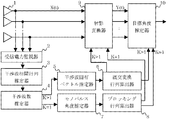
図1はこの発明の実施の形態1によるレーダ装置の構成を示すブロック図である。図において、アレーアンテナ1はレーダ波を受信するアレーアンテナ素子である。受信電力監視器2は、アレーアンテナ1が干渉波を受けているかどうかを判定する部位であって、干渉波を受けている場合に受信したデータベクトル(以後、単に受信ベクトルと呼ぶ)を出力するスイッチを備えている。なお、上記及び以降の説明において、部位という語は、素子又は回路によって構成されることを意味し、汎用のDSP(Digital Signal Processor)やCPU(Central Processing Unit)にコンピュータプログラムを組み合わせて、同様の機能を構成する場合を含むものとする。
Embodiments of the present invention will be described below with reference to the drawings.
1 is a block diagram showing a configuration of a radar apparatus according to
干渉波相関行列推定器3は、計測した干渉波の受信ベクトルから相関行列の推定値を得る部位である。干渉波数推定器4は、干渉波相関行列推定器3によって推定された干渉波の相関行列の固有展開を行い、固有値を求めて、雑音の固有値より大きい固有値の数を干渉波の数として算出する部位である。干渉波固有ベクトル推定器5は、干渉波数推定器4によって算出された干渉波数(図1においては、干渉波数をKとしている)が2以上である場合に、相関行列の固有値に対する固有ベクトル(すなわち干渉波固有ベクトル)を算出する部位である。直交変換行列算出器6は、干渉波固有ベクトルから直交変換行列として算出する部位である。 The interference wave correlation matrix estimator 3 is a part that obtains an estimated value of the correlation matrix from the measured interference wave reception vector. The interference wave number estimator 4 performs eigenexpansion of the correlation matrix of the interference wave estimated by the interference wave correlation matrix estimator 3, obtains an eigenvalue, and calculates the number of eigenvalues larger than the eigenvalue of noise as the number of interference waves. It is a part. When the interference wave number calculated by the interference wave number estimator 4 (the interference wave number is K in FIG. 1) is 2 or more, the interference wave eigenvector estimator 5 is an eigenvector (that is, an interference wave) corresponding to the eigenvalue of the correlation matrix. This is a part for calculating an eigenvector. The orthogonal transformation matrix calculator 6 is a part that calculates an orthogonal transformation matrix from the interference wave eigenvector.
モノパルス角度推定器7は、干渉波数推定器4によって算出された干渉波数が1の場合(K=1)に、その干渉波の到来角を推定する部位である。そして、ブロッキング行列算出器8は、モノパルス角度推定装置7によって推定された角度から干渉波を抑圧するためのブロッキング行列を算出する部位である。 The monopulse angle estimator 7 is a part that estimates the arrival angle of the interference wave when the interference wave number calculated by the interference wave number estimator 4 is 1 (K = 1). The blocking matrix calculator 8 is a part that calculates a blocking matrix for suppressing the interference wave from the angle estimated by the monopulse angle estimation device 7.
射影変換器9は、受信ベクトルを射影変換する部位である。射影変換に用いる行列は、K=1、すなわち干渉波数が1の場合はブロッキング行列であり、K>1、すなわち干渉波数が2以上の場合には直交変換射影行列である。目標角度推定器10は、射影変換器7によって射影変換され、干渉波が抑圧されたアレー素子数の次元をもつデータベクトルと、ブロッキング行列(K=1の場合)若しくは直交変換行列(K>1の場合)とを用いてMUSIC法やML法などの超分解能測角法による目標角度推定を行う部位である。
The projective converter 9 is a part that performs projective transformation on the received vector. The matrix used for the projective transformation is a blocking matrix when K = 1, that is, the interference wave number is 1, and is an orthogonal transformation projection matrix when K> 1, ie, the interference wave number is 2 or more. The
次に、この発明の実施の形態1によるレーダ装置の動作を説明する。受信電力監視器2は、アレーアンテナ1に自ら送信した送信波と異なる信号が入射している場合に、干渉波が入射しているものと判断し、干渉波のみの受信信号を計測する。具体的には、例えば、レーダ波を送信していない時間帯において、受信している受信信号が内部雑音よりも大きい場合に干渉波を受けていると判断する。受信電力監視器2は、干渉波を受けていると判断した場合、自らの備えるスイッチを出力端に接続して、アレーアンテナ1の受信した受信ベクトルを干渉波相関行列推定器3に出力する。
Next, the operation of the radar apparatus according to
干渉波相関行列推定器3は、計測した受信ベクトルのすべてのスナップショットの平均をとることで、相関行列Rを推定する。受信ベクトルをX(t)とし、受信ベクトルの複素共役をX(t)Hとした場合に、相関行列Rは式(1)によって与えられる。

次に、干渉波数推定器4は、相関行列Rの固有展開を行い、複数の固有値を求める。また雑音の固有値σ2より大きな値となる固有値の個数を求めて、この個数を干渉波の数Kと推定し、干渉波数Kと干渉波の相関行列の固有値とを出力する。 Next, the interference wave number estimator 4 performs eigenexpansion of the correlation matrix R to obtain a plurality of eigenvalues. Also, the number of eigenvalues that are larger than the noise eigenvalue σ 2 is obtained, this number is estimated as the number K of interference waves, and the interference wave number K and the eigenvalue of the correlation matrix of the interference waves are output.
K>1の場合には、干渉波固有ベクトル推定器5は、干渉波数推定器4によって算出された干渉波の相関行列の固有値に対する固有ベクトル(すなわち干渉波固有ベクトル)を算出する。そして直交変換行列算出器6は、単位行列から干渉波固有ベクトルの張る干渉波固有空間を減算して、直交変換行列を算出する。なお、以降の説明において、この直交変換行列をPとする。 In the case of K> 1, the interference wave eigenvector estimator 5 calculates an eigenvector (that is, an interference wave eigenvector) for the eigenvalue of the correlation matrix of the interference wave calculated by the interference wave number estimator 4. The orthogonal transformation matrix calculator 6 subtracts the interference wave eigenspace spanned by the interference wave eigenvector from the unit matrix to calculate an orthogonal transformation matrix. In the following description, this orthogonal transformation matrix is assumed to be P.
射影変換器9は、受信ベクトルX(t)に対し、先に求めておいた直交変換射影行列Pを左から乗算して、射影変換を行う。その結果、射影変換後の信号として、干渉波が抑圧されたアレー素子数だけの次元を有するデータベクトルが得られる。このように、通常のヌルビームフォーミングのように出力信号が1チャンネルになることもなく、アレー素子数だけの次元を有したまま射影変換を行うことで、ビーム幅を超える目標角度推定が可能となるのである。 The projective transformer 9 performs projective transformation by multiplying the received vector X (t) by the previously obtained orthogonal transform projection matrix P from the left. As a result, a data vector having dimensions corresponding to the number of array elements in which interference waves are suppressed is obtained as a signal after projective transformation. As described above, the output signal does not become one channel as in the case of normal null beam forming, and the target angle exceeding the beam width can be estimated by performing the projective transformation while having the dimensions corresponding to the number of array elements. It becomes.
続いて目標角度推定器10は、射影変換され干渉波が抑圧されたアレー素子数の次元をもつデータベクトルを取得する。そして、直交変換行列Pを用いて、測角に用いるアレーモードベクトル(Aとする)に対しても、受信ベクトルと同様に射影変換を行い、新たなアレーモードベクトル(Bとする。すなわちB=PA)を得る。このアレーモードベクトルBを用いて、例えばMUSIC法やML法などの超分解能測角法による目標角度推定を行う。このようにして、MUSIC法やML法を単独で用いた場合では、角度分離できないような状況でも、射影変換により干渉波を抑圧することで、干渉波と同一ビーム内に存在する目標の測角を可能とする。
Subsequently, the
一方、K=1の場合にあっては、モノパルス角度推定器7において、まず要求される覆域内の複数の指向方向θm(m=1,2,…、M、Mはビームの数)に対して、式(2)によって、和ビームΣm(t)と差ビームΔm(t)を算出する。
このマルチビーム和信号Σ(t)の振幅レベルから干渉波が存在するビーム方向θmを算出し、そのΣm(t)とΣm(t)から、比αを式(4)によって取得する。
ブロッキング行列算出器8は、干渉波角度θiから、そのアレーモードベクトルa(θi)で表される射影行列PBMを式(7)を用いて算出する。この射影行列PBMをブロッキング行列(BM:Blocking Matrix)と呼ぶ。
なお、ブロッキング行列では、アレーモードベクトルが式(3)で表される場合に、干渉波の到来方向θiに関わらずa(θi)Ha(θi)=Nとなり、ほぼa(θi)a(θi)Hの計算のみで射影行列を得ることができる。またブロッキング行列では直交変換行列より干渉波方向に、より深いヌルを形成できる。 In the blocking matrix, when the array mode vector is expressed by Equation (3), a (θ i ) H a (θ i ) = N regardless of the arrival direction θ i of the interference wave, and almost a (θ A projection matrix can be obtained only by calculating i ) a (θ i ) H. In the blocking matrix, deeper nulls can be formed in the interference wave direction than the orthogonal transformation matrix.
次に、射影変換器9は、アレーアンテナ1から受信ベクトルX(t)を取得し、ブロッキング行列PBMを用いて射影変換を行う。すなわち変換後のデータベクトルをY(t)とすれば、
式(8)によって算出されたデータベクトルY(t)は、干渉波が抑圧されたアレー素子数の次元を持つデータベクトルである。目標角度推定器10は、このデータベクトルY(t)を取得し、さらにブロッキング行列算出器8から射影変換に用いたブロッキング行列PBMを取得する。そして、アレーのモードベクトルAに対しても同様に射影変換を行って、新たなアレーモードベクトルBBM(=PBMA)を算出する。そしてこのアレーモードベクトルBBMをモードベクトルとして採用して、例えばMUSIC法やML法などの超分解能測角法、あるいはモノパルス測角法によって測定対象の目標の角度を算出する。
The data vector Y (t) calculated by the equation (8) is a data vector having a dimension of the number of array elements in which interference waves are suppressed. The
以上から明らかなように、この発明の実施の形態1のレーダ装置によれば、射影行列として直交変換行列ではなくブロッキング行列を用いることで、固有ベクトルの計算が不要となる。また、ブロッキング行列の算出は、上述のとおりa(θi)a(θi)Hの計算のみで行うことができるので、その点においても計算量を削減することができる。 As is apparent from the above, according to the radar apparatus of the first embodiment of the present invention, the calculation of eigenvectors becomes unnecessary by using a blocking matrix instead of an orthogonal transformation matrix as a projection matrix. Further, since the calculation of the blocking matrix can be performed only by calculating a (θ i ) a (θ i ) H as described above, the calculation amount can be reduced also in this respect.
さらにブロッキング行列を算出する過程において、モノパルス角度推定器7により干渉波の到来方向も得られる。したがって、MUSIC法やML法を単独で使用した場合には目標の角度推定が行えない状況であっても、干渉波の角度が得られ、ブロッキング行列を用いた射影変換によって干渉波が抑圧されて、目標の測角を行うことができる。 Further, in the process of calculating the blocking matrix, the arrival direction of the interference wave is also obtained by the monopulse angle estimator 7. Therefore, even when the MUSIC method or ML method is used alone, the angle of the interference wave is obtained even if the target angle cannot be estimated, and the interference wave is suppressed by projective transformation using a blocking matrix. The target angle can be measured.
実施の形態2.
実施の形態1のレーダ装置は、干渉波数が1(K=1)の場合に、モノパルス角度推定法とブロッキング行列とを用いて、干渉波を効率的に抑圧して目標角度を推定するものであった。これに対して、干渉波数が1より大きい場合(K>2)に、干渉波対内部雑音比(S/I)が小さい場合であっても、良好な干渉抑圧性能が得られる射影行列を用いて、干渉波を抑圧するようにしてもよい。この発明の実施の形態2によるレーダ装置は、このような特徴を有するものである。
Embodiment 2. FIG.
The radar apparatus according to
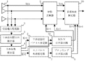
図2は、この発明の実施の形態2によるレーダ装置の構成を示すブロック図である。図において、MSN行列算出器11は、相関行列の逆行列を算出する部位である。その他、図1と同一の符号を付した構成要素については、実施の形態1と同様であるので、説明を省略する。
FIG. 2 is a block diagram showing a configuration of a radar apparatus according to Embodiment 2 of the present invention. In the figure, an
次に、この発明の実施の形態2によるレーダ装置の動作について説明する。実施の形態1のレーダ装置と同様にして、受信電力監視器2は干渉波の有無を判定し、さらに干渉波相関行列推定器3と干渉波数推定器4とを通じて、この発明の実施の形態2のレーダ装置は、干渉波の個数を推定する。ここでは、干渉波の個数(K)が2以上である場合(K>2)についてのみ説明する。 Next, the operation of the radar apparatus according to Embodiment 2 of the present invention will be described. Similarly to the radar apparatus according to the first embodiment, the reception power monitor 2 determines the presence or absence of an interference wave, and further passes through the interference wave correlation matrix estimator 3 and the interference wave number estimator 4 in the second embodiment of the present invention. The radar apparatus estimates the number of interference waves. Here, only the case where the number (K) of interference waves is 2 or more (K> 2) will be described.
K>1の場合、干渉波固有ベクトル推定器5は、固有展開を用いた測角法、例えばMUSIC法を用いて、干渉波の角度を推定する。MUSIC法では、波数推定で求めた干渉波の相関行列Rの固有値から、雑音の固有値に対応する固有ベクトルen(n=1,2,…,N−K)からなる雑音空間E=[e1 e2 … eN−K]を求める。なお、Nは素子数である。 When K> 1, the interference wave eigenvector estimator 5 estimates the angle of the interference wave using an angle measurement method using eigenexpansion, for example, the MUSIC method. In the MUSIC method, a noise space E = [e 1 which is composed of eigenvectors e n (n = 1, 2,..., N−K) corresponding to eigenvalues of noise from eigenvalues of correlation matrix R of interference waves obtained by wave number estimation. e 2 ... e N−K ]. N is the number of elements.
次にMSN行列算出器11は、相関行列Rの逆行列PMSN(=R−1)を算出する。相関行列Rは、干渉波固有ベクトル推定器5で算出された干渉波固有ベクトルenを用いて、
ここで求めたPMSNはMSN(Maximum Signal to noise ratio)法において、所望の方向θに対するモードベクトルv=a(θ)からウエイトベクトルwを求める上で用いる式(12)で示す相関行列の逆行列R−1である。
また、干渉波の相関行列Rが変動する場合には、式(11)で求めたR−1を初期値として漸化式
なお、干渉波の固有値λk≫σ2のとき(干渉波の固有値が雑音の分散値に比して十分大きいとき)
射影変換器9は、直交変換行列に替えて、相関行列の逆行列を用いて受信ベクトルX(t)を射影変換し、データベクトルY(t)を式(8)によって算出する。そして目標角度推定器10は、MSN行列算出器11が算出したアレーのモードベクトルを用いて、目標の角度を推定して出力する。
The projective transformer 9 performs projective transformation on the received vector X (t) using the inverse matrix of the correlation matrix instead of the orthogonal transform matrix, and calculates the data vector Y (t) by the equation (8). The
以上から明らかなように、この発明の実施の形態2のレーダ装置によれば、干渉波が雑音(内部雑音)に比べて十分大きくない場合にも入出力のS/N比が最大となる相関行列の逆行列を用いて受信ベクトルを射影変換することにより、干渉波抑圧を行うことができる。 As is apparent from the above, according to the radar apparatus of the second embodiment of the present invention, the correlation at which the input / output S / N ratio is maximized even when the interference wave is not sufficiently larger than the noise (internal noise). Interference wave suppression can be performed by projective transformation of the received vector using the inverse matrix.
さらに、相関行列の逆行列の算出に必要となる固有値は、干渉波の波数推定時に算出したものを使用すればよいので、直交変換行列を用いる場合と比べて計算量が増えることもない。 Furthermore, since the eigenvalue required for calculating the inverse matrix of the correlation matrix may be the one calculated at the time of estimating the wave number of the interference wave, the amount of calculation does not increase compared to the case where the orthogonal transformation matrix is used.
実施の形態3.
実施の形態1及び2によるレーダ装置では、干渉波を抑圧することができるが、目標の角度を得るためにすべての時間サンプルで目標角度の推定演算を行う必要があり、そのために演算量が大きくなっている。そこで、この問題を解決するために、射影変換されたアンテナ素子データからマルチビームを形成し、目標のビーム方向の範囲に限定して角度推定を行うようにしてもよい。この発明の実施の形態3によるレーダ装置は、かかる特徴を有するものである。
Embodiment 3 FIG.
In the radar apparatus according to the first and second embodiments, interference waves can be suppressed. However, in order to obtain a target angle, it is necessary to perform an estimation calculation of the target angle at all time samples. It has become. Therefore, in order to solve this problem, a multi-beam may be formed from the antenna element data subjected to the projective transformation, and angle estimation may be performed by limiting the range to the target beam direction. The radar apparatus according to Embodiment 3 of the present invention has such a feature.
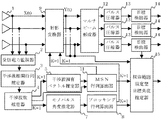
図3は、この発明の実施の形態3によるレーダ装置の構成を示すブロック図である。図において、マルチビーム形成器12は、データベクトルからマルチビーム形成を行う部位である。また、パルス圧縮器13は、マルチビーム形成されたビーム毎にパルス圧縮を行う部位である。目標検出器14は、マルチビーム形成されたビーム毎に限定して目標検出を行う部位であり、探索範囲限定型目標角度推定器15は、目標が含まれる遅延時間を限定して、角度推定を行う部位である。なお、その他図2と同一の符号を付した構成要素については、実施の形態2と同様であるので、説明を省略する。
FIG. 3 is a block diagram showing a configuration of a radar apparatus according to Embodiment 3 of the present invention. In the figure, a multi-beam former 12 is a part that performs multi-beam formation from a data vector. The
次に、この発明の実施の形態3によるレーダ装置の動作について、図を用いて説明する。このレーダ装置においても、アレーアンテナ1や受信電力監視器2、干渉波相関行列推定器3、干渉波数推定器4,干渉波固有ベクトル推定器5、モノパルス角度推定器7、ブロッキング行列算出器8、射影変換器9の動作は、実施の形態2と同様に動作する。したがって、例えば射影変換器9は、受信ベクトルX(t)を射影変換して、データベクトルY(t)を出力し、MSN行列算出器11は相関行列の逆行列を算出する。
Next, the operation of the radar apparatus according to Embodiment 3 of the present invention will be described with reference to the drawings. Also in this radar apparatus, the
そこで、マルチビーム形成器12は、データベクトルY(t)を用いて、要求覆域内にマルチビームを配置するためにθm方向へのステアリングベクトルをvm(=a(θm))(m=1,2,…,M、Mはビームの個数)として、
次に、パルス圧縮器13は、各ビーム毎に式(16)で得られたデータベクトルZm(t)(ここでは送信波はPN符号信号とする)をパルス圧縮する。その結果、パルス圧縮器13は、目標の反射を1チップ幅(1つのバイナリフェーズの時間幅)相当の距離サンプルに圧縮する。ここで、パルス圧縮されたデータベクトルをZpm(t)(m=1,2,…,M)とする。続いて、目標検出器14は、パルス圧縮された各ビーム毎のデータベクトルZpm(t)を距離方向について閾値処理する。そしてその結果、目標検出を行って、目標の遅延時間tsを得る。こうして、目標が含まれるビーム方向vmと距離R(=2ts/c)が得られる。
Next, the
一方で、探索範囲限定型目標角度推定器15は、目標検出器14で得られたビーム方向vmと遅延時間tsとを取得して、目標の角度推定を行う時間サンプルを目標が含まれる遅延時間tsに限定し、かつMUSIC法やML法を用いた角度推定では、その探索範囲を目標が含まれるビーム方向vmに限定して角度推定を行う。 On the other hand, the search range-limited target angle estimator 15 obtains the beam direction obtained by the target detector 14 v m and the delay time t s, includes the target time samples performed the target angle estimate restricted to the delay time t s, and the angle estimation using the MUSIC method or ML method, performs angle estimation limit its search range in the beam direction v m that contains target.
以上から明らかなように、この発明の実施の形態3のレーダ装置によれば、射影変換されたデータベクトルからマルチビーム形成およびパルス圧縮を行うことで、S/Nを改善し、目標の検出を行うようにしたので、目標の時間遅延(すなわち距離)が得られるとともに、目標の角度推定においてすべての時間サンプルと要求角度範囲で角度推定をおこなう必要がなく、目標角度推定の計算量を削減可能となる。 As is apparent from the above, according to the radar apparatus of the third embodiment of the present invention, the S / N is improved and target detection is performed by performing multi-beam formation and pulse compression from the projection-transformed data vector. As a result, target time delay (ie, distance) can be obtained, and target angle estimation does not need to be performed for all time samples and the required angle range, reducing the amount of calculation for target angle estimation. It becomes.
なお、ビーム幅と要求される覆域などの条件によっては、ウエイトベクトルwm(=Pvm)を用いて式(10)によって、逐次ビーム形成し、距離方向の閾値処理から目標が検出されたときにのみ、その遅延時間tsのデータベクトルX(ts)に対して式(8)による射影変換を行うようにしてもよい。このようにすることで、さらに計算量が少なくすることができる。 Depending on the conditions such as the beam width and the required coverage, the beam is sequentially formed by the equation (10) using the weight vector w m (= Pv m ), and the target is detected from the threshold processing in the distance direction. only, it may be performed projective transformation by the formula (8) with respect to the data vector X of the delay time t s (t s) when. By doing so, the amount of calculation can be further reduced.
実施の形態4.
実施の形態1乃至3では、干渉波として対向車のレーダ装置が放射したレーダ波を主として想定していた。しかし、実際の使用環境下では、自らの送信波が路面などに反射され、その結果、不要反射波(クラッタ)としてレーダアンテナに入射することもある。このような場合には、各距離(時間サンプル)に対しパルス方向にFFT処理を行うパルスドップラフィルタ処理によりフィルタバンクを形成して、自速から予想される路面反射クラッタのドップラ周波数に相当するパルスドップラフィルタ以外のフィルタのみを選択するようにしてもよい。この発明の実施の形態4によるレーダ装置は、かかる特徴を有するものである。
Embodiment 4 FIG.
In the first to third embodiments, the radar wave radiated from the radar device of the oncoming vehicle is mainly assumed as the interference wave. However, in an actual use environment, the own transmitted wave is reflected on the road surface or the like, and as a result, it may enter the radar antenna as an unnecessary reflected wave (clutter). In such a case, a filter bank is formed by pulse Doppler filter processing that performs FFT processing in the pulse direction for each distance (time sample), and a pulse corresponding to the Doppler frequency of the road surface reflection clutter expected from its own speed. Only a filter other than the Doppler filter may be selected. The radar apparatus according to Embodiment 4 of the present invention has such a feature.
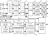
図4は、この発明の実施の形態4によるレーダ装置の構成を示すブロック図である。図において、パルスドップラフィルタ16は、データベクトルY(t)をパルス方向について高速フーリエ変換する部位である。また、パルスドップラフィルタ選択器17は、複数のパルスドップラフィルタバンクからクラッタが含まれないフィルタを選択する部位である。なお、その他図3と同一の符号を付した構成要素については、実施の形態3と同様であるので、説明を省略する。
4 is a block diagram showing a configuration of a radar apparatus according to Embodiment 4 of the present invention. In the figure, a
次に、この発明の実施の形態4によるレーダ装置の動作について、図を用いて説明する。このレーダ装置においても、アレーアンテナ1や受信電力監視器2、干渉波相関行列推定器3、干渉波数推定器4,干渉波固有ベクトル推定器5、モノパルス角度推定器7、ブロッキング行列算出器8、射影変換器9の動作は、実施の形態3と同様に動作する。したがって、例えば射影変換器9は、受信ベクトルX(t)を射影変換して、データベクトルY(t)を出力する。
Next, the operation of the radar apparatus according to Embodiment 4 of the present invention will be described with reference to the drawings. Also in this radar apparatus, the
射影変換器9がデータベクトルY(t)を出力すると、パルスドップラフィルタ16は、射影変換されたデータベクトルY(t)をパルス方向について高速フーリエ変換する。クラッタのドップラ周波数は自速に依存した既知量とみなすことができる。そこで、パルスドップラフィルタ選択器17は、パルスドップラフィルタバンクからクラッタが含まれないフィルタを選択する。これは受信ベクトルの電力と内部雑音電力との比較をすることによってなされる。選択されたパルスドップラフィルタにはクラッタが含まれず内部雑音のみが含まれることになる。
When the projecting transformer 9 outputs the data vector Y (t), the
続いて、マルチビーム形成器12は、選択されたフィルタ毎にマルチビーム形成を行う。このようにして、マルチビーム形成器12は、ビーム方向とパルスドップラフィルタ番号とによって規定される時間方向のデータベクトルを出力する。パルス圧縮器13は、このデータベクトルをパルス圧縮し、さらに目標検出器14はパルス圧縮されたデータベクトルに対して、距離方向への閾値処理を行い、目標検出する。
Subsequently, the multi-beamformer 12 performs multi-beam formation for each selected filter. In this way, the multi-beamformer 12 outputs a data vector in the time direction defined by the beam direction and the pulse Doppler filter number. The
このようにして、目標検出器14は、目標が含まれるビーム方向vmと距離R(=2ts/c)とパルスドップラフィルタ番号とを得る。探索範囲限定型目標角度推定器15は、目標が検出されたパルスドップラフィルタ番号の遅延時間tsにおけるデータベクトルを用いて、目標が検出されたビーム方向vmに範囲を限定した角度推定を行う。
In this way, the
以上から明らかなように、この発明の実施の形態4のレーダ装置によれば、自らによる送信波が路面などに反射されてクラッタとしてレーダアンテナに入射する場合において、パルスドップラフィルタを組み合わせることによってクラッタを抑圧し、目標の距離、ドップラ周波数、角度を得ることができる。 As is apparent from the above, according to the radar apparatus of the fourth embodiment of the present invention, when a transmission wave by itself is reflected on the road surface or the like and is incident on the radar antenna as clutter, by combining the pulse Doppler filter, And the target distance, Doppler frequency, and angle can be obtained.
この発明に係るレーダ装置は、例えば、車載用途のレーダ装置などとして利用することができる。 The radar apparatus according to the present invention can be used as, for example, a radar apparatus for in-vehicle use.
1 アレーアンテナ、
2 受信電力監視器、
3 干渉波相関行列推定器、
4 干渉波数推定器、
5 干渉波固有ベクトル推定器、
6 直交変換行列算出器、
7 モノパルス角度推定器、
8 ブロッキング行列算出器、
9 射影変換器、
10 目標角度推定器、
11 MSN行列算出器、
12 マルチビーム形成器、
13 パルス圧縮器、
14 目標検出器、
15 探索範囲限定型目標角度推定器、
16 パルスドップラフィルタ、
17 パルスドップラフィルタ選択器。
1 array antenna,
2 Received power monitor,
3 interference wave correlation matrix estimator,
4 Interference wave number estimator,
5 interference wave eigenvector estimator,
6 Orthogonal transformation matrix calculator,
7 Monopulse angle estimator,
8 Blocking matrix calculator,
9 Projection converter,
10 Target angle estimator,
11 MSN matrix calculator,
12 Multi-beamformer,
13 Pulse compressor,
14 target detector,
15 Search range limited type target angle estimator,
16 Pulse Doppler filter,
17 Pulse Doppler filter selector.
Claims (4)
レーダ波を送信していない時間帯に前記アレーアンテナが受信した干渉波のデータベクトルに対する相関行列の固有値を求め、この求めた固有値の数を干渉波の数Kと推定する干渉波数推定手段と、
K=1の場合にモノパルス測角法を利用して前記受信ベクトルが含む干渉波を抑圧し、K>1の場合に前記干渉波数推定手段が求めた相関行列の固有値に基づいて前記受信ベクトルが含む干渉波を抑圧してデータベクトルを出力する干渉波抑圧手段と、
前記干渉波抑圧手段が出力したデータベクトルに超分解能測角法を適用して前記測定対象の反射波の到来方向を算出する目標角度推定手段と、
を備えたことを特徴とするレーダ装置。 An array antenna that receives a reflected wave from a measurement object and outputs a reception vector;
Interference wave number estimating means for obtaining eigenvalues of a correlation matrix for a data vector of interference waves received by the array antenna in a time zone during which no radar wave is transmitted, and estimating the number of the obtained eigenvalues as the number K of interference waves;
When K = 1, the interference wave included in the reception vector is suppressed using a monopulse angle measurement method. When K> 1, the reception vector is determined based on the eigenvalue of the correlation matrix obtained by the interference wave number estimation means. Interference wave suppressing means for suppressing the including interference wave and outputting the data vector;
Target angle estimation means for calculating the arrival direction of the reflected wave of the measurement object by applying a super-resolution angle measurement method to the data vector output by the interference wave suppression means;
Radar equipment, characterized in that it comprises a.
前記マルチビーム形成手段により形成されたビーム毎に前記データベクトルをパルス圧縮するパルス圧縮手段と、
前記パルス圧縮手段によりパルス圧縮されたデータベクトルから目標検出を行う目標検出手段と、を備え、
前記目標角度推定手段は、前記目標検出手段が目標を検出したビームの範囲に限定して目標角度演算を行うことを特徴とする請求項2に記載のレーダ装置。 Multi-beam forming means for forming a multi-beam from the data vector output by the interference wave suppressing means;
Pulse compression means for pulse-compressing the data vector for each beam formed by the multi-beam forming means;
Target detection means for performing target detection from the data vector pulse-compressed by the pulse compression means,
The radar apparatus according to claim 2, wherein the target angle estimation unit performs target angle calculation limited to a range of a beam in which the target detection unit detects a target.
前記パルスドップラーフィルタが周波数解析した結果に基づいて、前記データベクトルからクラッタを含まないデータベクトルを選択するパルスドップラー選択手段と、を備え、
前記マルチビーム形成手段は、前記パルスドップラー選択手段が選択したデータベクトルからマルチビームを形成することを特徴とする請求項3に記載のレーダ装置。 A pulse Doppler filter that analyzes the frequency of the data vector output by the interference wave suppression means for each antenna element;
Pulse Doppler selection means for selecting a data vector not including clutter from the data vector based on a result of frequency analysis performed by the pulse Doppler filter, and
4. The radar apparatus according to claim 3, wherein the multi-beam forming unit forms a multi-beam from the data vector selected by the pulse Doppler selecting unit.
Priority Applications (1)
| Application Number | Priority Date | Filing Date | Title |
|---|---|---|---|
| JP2003359149A JP4972852B2 (en) | 2003-10-20 | 2003-10-20 | Radar equipment |
Applications Claiming Priority (1)
| Application Number | Priority Date | Filing Date | Title |
|---|---|---|---|
| JP2003359149A JP4972852B2 (en) | 2003-10-20 | 2003-10-20 | Radar equipment |
Publications (2)
| Publication Number | Publication Date |
|---|---|
| JP2005121581A JP2005121581A (en) | 2005-05-12 |
| JP4972852B2 true JP4972852B2 (en) | 2012-07-11 |
Family
ID=34615471
Family Applications (1)
| Application Number | Title | Priority Date | Filing Date |
|---|---|---|---|
| JP2003359149A Expired - Fee Related JP4972852B2 (en) | 2003-10-20 | 2003-10-20 | Radar equipment |
Country Status (1)
| Country | Link |
|---|---|
| JP (1) | JP4972852B2 (en) |
Families Citing this family (22)
| Publication number | Priority date | Publication date | Assignee | Title |
|---|---|---|---|---|
| JP2983142B2 (en) * | 1994-08-03 | 1999-11-29 | 京葉瓦斯株式会社 | Gas lamp mantle |
| JP4602267B2 (en) * | 2006-02-27 | 2010-12-22 | 株式会社デンソーアイティーラボラトリ | Electronic scanning radar equipment |
| JP4986284B2 (en) * | 2007-02-09 | 2012-07-25 | 株式会社東芝 | Weight calculation method, weight calculation device, adaptive array antenna, and radar device |
| JP5247068B2 (en) * | 2007-06-05 | 2013-07-24 | 三菱電機株式会社 | Radar equipment |
| JP5116402B2 (en) * | 2007-08-20 | 2013-01-09 | 三菱電機株式会社 | Angle measuring device |
| JP5478010B2 (en) * | 2007-11-12 | 2014-04-23 | 株式会社デンソーアイティーラボラトリ | Electronic scanning radar equipment |
| JP5371248B2 (en) * | 2008-01-07 | 2013-12-18 | 三菱電機株式会社 | Radar equipment |
| JP5625326B2 (en) * | 2009-11-11 | 2014-11-19 | 日本電気株式会社 | Radar apparatus and distance measurement method thereof |
| CN102830386B (en) * | 2012-09-03 | 2014-05-07 | 西安建筑科技大学 | Estimation method of arbitrary array weak signal source angle under strong interference |
| JP6271834B2 (en) * | 2012-11-20 | 2018-01-31 | 三菱電機株式会社 | Radar equipment |
| JP6265605B2 (en) * | 2013-02-21 | 2018-01-24 | 三菱電機株式会社 | Target angle measuring device |
| CN103792518B (en) * | 2014-01-28 | 2015-11-11 | 北京川速微波科技有限公司 | A kind of Microwave Velocity radar environments disturbance ecology and suppressing method |
| JP6296907B2 (en) * | 2014-06-06 | 2018-03-20 | 株式会社東芝 | Radar apparatus and radar signal processing method thereof |
| JP6608127B2 (en) * | 2014-06-30 | 2019-11-20 | 日本無線株式会社 | Interference suppression support device |
| KR101553878B1 (en) | 2015-02-06 | 2015-09-17 | 엘아이지넥스원 주식회사 | Method for compressing side lobe level of transmit switching radar system |
| KR101553877B1 (en) | 2015-02-06 | 2015-09-17 | 엘아이지넥스원 주식회사 | Transmit switching radar system for compressing side lobe level |
| JP6632466B2 (en) * | 2016-05-09 | 2020-01-22 | 三菱電機株式会社 | Receiving apparatus and receiving method, and program and recording medium |
| CN109507649B (en) * | 2018-12-20 | 2022-12-02 | 西安电子科技大学 | Method for resisting main lobe deception jamming of wave diversity array radar |
| CN111239677B (en) * | 2020-01-03 | 2023-10-31 | 中国航天科工集团八五一一研究所 | Multi-beam passive monopulse angle measurement method based on digital array |
| CN113466801B (en) * | 2021-05-13 | 2023-03-07 | 西安电子科技大学 | Circular array-based secondary radar space-time main lobe interference resisting method |
| JP7383204B2 (en) * | 2021-08-06 | 2023-11-17 | 三菱電機株式会社 | radar equipment |
| CN116840775B (en) * | 2023-06-30 | 2024-02-27 | 中国人民解放军军事科学院系统工程研究院 | Weak signal extraction method for known strong signal scene |
Family Cites Families (10)
| Publication number | Priority date | Publication date | Assignee | Title |
|---|---|---|---|---|
| JPS628082A (en) * | 1985-07-03 | 1987-01-16 | Oki Electric Ind Co Ltd | Tracking system in sonar |
| JPH07280918A (en) * | 1994-04-05 | 1995-10-27 | Mitsubishi Electric Corp | Apparatus for suppressing jamming waves |
| US6141371A (en) * | 1996-12-18 | 2000-10-31 | Raytheon Company | Jamming suppression of spread spectrum antenna/receiver systems |
| JP3647621B2 (en) * | 1997-11-07 | 2005-05-18 | 三菱電機株式会社 | Radio direction detector |
| JP3563579B2 (en) * | 1997-11-26 | 2004-09-08 | 株式会社東芝 | DBF radar device |
| JP4163294B2 (en) * | 1998-07-31 | 2008-10-08 | 株式会社東芝 | Noise suppression processing apparatus and noise suppression processing method |
| JP4577742B2 (en) * | 2000-11-14 | 2010-11-10 | 住友電気工業株式会社 | Radio wave arrival direction estimation device |
| JP3710409B2 (en) * | 2001-10-30 | 2005-10-26 | 三菱電機株式会社 | Receiving array antenna calibration device |
| JP3557463B2 (en) * | 2001-12-28 | 2004-08-25 | 防衛庁技術研究本部長 | Super resolution antenna |
| JP4187985B2 (en) * | 2002-03-15 | 2008-11-26 | 三菱電機株式会社 | Angle measuring device, angle measuring method and program |
-
2003
- 2003-10-20 JP JP2003359149A patent/JP4972852B2/en not_active Expired - Fee Related
Also Published As
| Publication number | Publication date |
|---|---|
| JP2005121581A (en) | 2005-05-12 |
Similar Documents
| Publication | Publication Date | Title |
|---|---|---|
| JP4972852B2 (en) | Radar equipment | |
| US8928522B2 (en) | Radar device | |
| US11340342B2 (en) | Automotive radar using 3D printed luneburg lens | |
| US7847733B2 (en) | Direction-of-arrival estimating device and program | |
| US7912680B2 (en) | Direction-of-arrival estimation apparatus | |
| JP6004694B2 (en) | Radar apparatus and target detection method | |
| JP4727311B2 (en) | Radar equipment | |
| US20030140771A1 (en) | Music spectrum calculating method, device and medium | |
| CN108885254B (en) | Object detection device | |
| CN109581352B (en) | Super-resolution angle measurement system based on millimeter wave radar | |
| US11269070B2 (en) | Radar apparatus | |
| CN106486769B (en) | Spatial interpolation method and apparatus for linear phased array antenna | |
| KR101468548B1 (en) | Radar Apparatus and Method for Estimating Direction of Arrival in the same | |
| JP2018197710A (en) | Radar signal processor | |
| JP4232628B2 (en) | Radar equipment | |
| JP5116590B2 (en) | Wave number estimation device | |
| JP5047002B2 (en) | Wave number estimation device | |
| KR101796472B1 (en) | Radar apparatus and DOA estimation method using the same | |
| JP4977849B2 (en) | Radio wave arrival direction detector | |
| KR102099388B1 (en) | Method of estimating direction of arrival of radar signal based on antenna array extrapolation and apparatus for the same | |
| Lee et al. | Enhanced performance of MUSIC algorithm using spatial interpolation in automotive FMCW radar systems | |
| KR20190124488A (en) | Method of signal subspace based DoA estimation for automotive radar system | |
| JP6287674B2 (en) | Delay time estimation device and height measurement device | |
| WO2021196165A1 (en) | Frequency analysis method, device and radar | |
| US20210141053A1 (en) | System and method for generating point cloud data in a radar based object detection |
Legal Events
| Date | Code | Title | Description |
|---|---|---|---|
| A621 | Written request for application examination |
Free format text: JAPANESE INTERMEDIATE CODE: A621 Effective date: 20060830 |
|
| A977 | Report on retrieval |
Free format text: JAPANESE INTERMEDIATE CODE: A971007 Effective date: 20081226 |
|
| A131 | Notification of reasons for refusal |
Free format text: JAPANESE INTERMEDIATE CODE: A131 Effective date: 20100216 |
|
| A521 | Request for written amendment filed |
Free format text: JAPANESE INTERMEDIATE CODE: A523 Effective date: 20100323 |
|
| A131 | Notification of reasons for refusal |
Free format text: JAPANESE INTERMEDIATE CODE: A131 Effective date: 20110322 |
|
| A521 | Request for written amendment filed |
Free format text: JAPANESE INTERMEDIATE CODE: A523 Effective date: 20110427 |
|
| TRDD | Decision of grant or rejection written | ||
| A01 | Written decision to grant a patent or to grant a registration (utility model) |
Free format text: JAPANESE INTERMEDIATE CODE: A01 Effective date: 20120313 |
|
| A01 | Written decision to grant a patent or to grant a registration (utility model) |
Free format text: JAPANESE INTERMEDIATE CODE: A01 |
|
| A61 | First payment of annual fees (during grant procedure) |
Free format text: JAPANESE INTERMEDIATE CODE: A61 Effective date: 20120326 |
|
| R151 | Written notification of patent or utility model registration |
Ref document number: 4972852 Country of ref document: JP Free format text: JAPANESE INTERMEDIATE CODE: R151 |
|
| FPAY | Renewal fee payment (event date is renewal date of database) |
Free format text: PAYMENT UNTIL: 20150420 Year of fee payment: 3 |
|
| R250 | Receipt of annual fees |
Free format text: JAPANESE INTERMEDIATE CODE: R250 |
|
| R250 | Receipt of annual fees |
Free format text: JAPANESE INTERMEDIATE CODE: R250 |
|
| R250 | Receipt of annual fees |
Free format text: JAPANESE INTERMEDIATE CODE: R250 |
|
| R250 | Receipt of annual fees |
Free format text: JAPANESE INTERMEDIATE CODE: R250 |
|
| R250 | Receipt of annual fees |
Free format text: JAPANESE INTERMEDIATE CODE: R250 |
|
| R250 | Receipt of annual fees |
Free format text: JAPANESE INTERMEDIATE CODE: R250 |
|
| LAPS | Cancellation because of no payment of annual fees |