EP3736378B1 - Einbaubohle mit schnellkupplung für aussenbedienstand - Google Patents
Einbaubohle mit schnellkupplung für aussenbedienstand Download PDFInfo
- Publication number
- EP3736378B1 EP3736378B1 EP19173275.9A EP19173275A EP3736378B1 EP 3736378 B1 EP3736378 B1 EP 3736378B1 EP 19173275 A EP19173275 A EP 19173275A EP 3736378 B1 EP3736378 B1 EP 3736378B1
- Authority
- EP
- European Patent Office
- Prior art keywords
- paving screed
- external control
- paving
- plug
- connection device
- Prior art date
- Legal status (The legal status is an assumption and is not a legal conclusion. Google has not performed a legal analysis and makes no representation as to the accuracy of the status listed.)
- Active
Links
- 238000010168 coupling process Methods 0.000 title claims description 30
- 230000008878 coupling Effects 0.000 title claims description 17
- 238000005859 coupling reaction Methods 0.000 title claims description 17
- 230000007246 mechanism Effects 0.000 claims description 7
- 230000001681 protective effect Effects 0.000 claims description 6
- 238000010276 construction Methods 0.000 description 5
- 238000009434 installation Methods 0.000 description 3
- 230000008901 benefit Effects 0.000 description 2
- 230000000694 effects Effects 0.000 description 2
- 230000006872 improvement Effects 0.000 description 2
- 238000011109 contamination Methods 0.000 description 1
- 230000001419 dependent effect Effects 0.000 description 1
- 238000011161 development Methods 0.000 description 1
- 230000018109 developmental process Effects 0.000 description 1
- 238000000034 method Methods 0.000 description 1
- 238000003032 molecular docking Methods 0.000 description 1
- 230000003287 optical effect Effects 0.000 description 1
- 230000008569 process Effects 0.000 description 1
- 230000000284 resting effect Effects 0.000 description 1
Images


Classifications
-
- B—PERFORMING OPERATIONS; TRANSPORTING
- B60—VEHICLES IN GENERAL
- B60R—VEHICLES, VEHICLE FITTINGS, OR VEHICLE PARTS, NOT OTHERWISE PROVIDED FOR
- B60R11/00—Arrangements for holding or mounting articles, not otherwise provided for
-
- E—FIXED CONSTRUCTIONS
- E01—CONSTRUCTION OF ROADS, RAILWAYS, OR BRIDGES
- E01C—CONSTRUCTION OF, OR SURFACES FOR, ROADS, SPORTS GROUNDS, OR THE LIKE; MACHINES OR AUXILIARY TOOLS FOR CONSTRUCTION OR REPAIR
- E01C19/00—Machines, tools or auxiliary devices for preparing or distributing paving materials, for working the placed materials, or for forming, consolidating, or finishing the paving
- E01C19/48—Machines, tools or auxiliary devices for preparing or distributing paving materials, for working the placed materials, or for forming, consolidating, or finishing the paving for laying-down the materials and consolidating them, or finishing the surface, e.g. slip forms therefor, forming kerbs or gutters in a continuous operation in situ
-
- B—PERFORMING OPERATIONS; TRANSPORTING
- B60—VEHICLES IN GENERAL
- B60R—VEHICLES, VEHICLE FITTINGS, OR VEHICLE PARTS, NOT OTHERWISE PROVIDED FOR
- B60R11/00—Arrangements for holding or mounting articles, not otherwise provided for
- B60R11/02—Arrangements for holding or mounting articles, not otherwise provided for for radio sets, television sets, telephones, or the like; Arrangement of controls thereof
- B60R11/0264—Arrangements for holding or mounting articles, not otherwise provided for for radio sets, television sets, telephones, or the like; Arrangement of controls thereof for control means
-
- E—FIXED CONSTRUCTIONS
- E01—CONSTRUCTION OF ROADS, RAILWAYS, OR BRIDGES
- E01C—CONSTRUCTION OF, OR SURFACES FOR, ROADS, SPORTS GROUNDS, OR THE LIKE; MACHINES OR AUXILIARY TOOLS FOR CONSTRUCTION OR REPAIR
- E01C19/00—Machines, tools or auxiliary devices for preparing or distributing paving materials, for working the placed materials, or for forming, consolidating, or finishing the paving
- E01C19/22—Machines, tools or auxiliary devices for preparing or distributing paving materials, for working the placed materials, or for forming, consolidating, or finishing the paving for consolidating or finishing laid-down unset materials
- E01C19/30—Tamping or vibrating apparatus other than rollers ; Devices for ramming individual paving elements
- E01C19/34—Power-driven rammers or tampers, e.g. air-hammer impacted shoes for ramming stone-sett paving; Hand-actuated ramming or tamping machines, e.g. tampers with manually hoisted dropping weight
- E01C19/40—Power-driven rammers or tampers, e.g. air-hammer impacted shoes for ramming stone-sett paving; Hand-actuated ramming or tamping machines, e.g. tampers with manually hoisted dropping weight adapted to impart a smooth finish to the paving, e.g. tamping or vibrating finishers
- E01C19/405—Power-driven rammers or tampers, e.g. air-hammer impacted shoes for ramming stone-sett paving; Hand-actuated ramming or tamping machines, e.g. tampers with manually hoisted dropping weight adapted to impart a smooth finish to the paving, e.g. tamping or vibrating finishers with spreading-out, levelling or smoothing means other than the tamping or vibrating means for compacting or smoothing, e.g. with screws for spreading-out the previously dumped material, with non-vibratory lengthwise reciprocated smoothing beam
-
- B—PERFORMING OPERATIONS; TRANSPORTING
- B60—VEHICLES IN GENERAL
- B60R—VEHICLES, VEHICLE FITTINGS, OR VEHICLE PARTS, NOT OTHERWISE PROVIDED FOR
- B60R11/00—Arrangements for holding or mounting articles, not otherwise provided for
- B60R2011/0001—Arrangements for holding or mounting articles, not otherwise provided for characterised by position
- B60R2011/004—Arrangements for holding or mounting articles, not otherwise provided for characterised by position outside the vehicle
-
- B—PERFORMING OPERATIONS; TRANSPORTING
- B60—VEHICLES IN GENERAL
- B60R—VEHICLES, VEHICLE FITTINGS, OR VEHICLE PARTS, NOT OTHERWISE PROVIDED FOR
- B60R11/00—Arrangements for holding or mounting articles, not otherwise provided for
- B60R2011/0042—Arrangements for holding or mounting articles, not otherwise provided for characterised by mounting means
- B60R2011/0049—Arrangements for holding or mounting articles, not otherwise provided for characterised by mounting means for non integrated articles
- B60R2011/0064—Connection with the article
-
- E—FIXED CONSTRUCTIONS
- E01—CONSTRUCTION OF ROADS, RAILWAYS, OR BRIDGES
- E01C—CONSTRUCTION OF, OR SURFACES FOR, ROADS, SPORTS GROUNDS, OR THE LIKE; MACHINES OR AUXILIARY TOOLS FOR CONSTRUCTION OR REPAIR
- E01C23/00—Auxiliary devices or arrangements for constructing, repairing, reconditioning, or taking-up road or like surfaces
- E01C23/01—Devices or auxiliary means for setting-out or checking the configuration of new surfacing, e.g. templates, screed or reference line supports; Applications of apparatus for measuring, indicating, or recording the surface configuration of existing surfacing, e.g. profilographs
-
- E—FIXED CONSTRUCTIONS
- E01—CONSTRUCTION OF ROADS, RAILWAYS, OR BRIDGES
- E01C—CONSTRUCTION OF, OR SURFACES FOR, ROADS, SPORTS GROUNDS, OR THE LIKE; MACHINES OR AUXILIARY TOOLS FOR CONSTRUCTION OR REPAIR
- E01C2301/00—Machine characteristics, parts or accessories not otherwise provided for
- E01C2301/14—Extendable screeds
- E01C2301/16—Laterally slidable screeds
-
- H—ELECTRICITY
- H05—ELECTRIC TECHNIQUES NOT OTHERWISE PROVIDED FOR
- H05K—PRINTED CIRCUITS; CASINGS OR CONSTRUCTIONAL DETAILS OF ELECTRIC APPARATUS; MANUFACTURE OF ASSEMBLAGES OF ELECTRICAL COMPONENTS
- H05K5/00—Casings, cabinets or drawers for electric apparatus
- H05K5/0017—Casings, cabinets or drawers for electric apparatus with operator interface units
Definitions
- the present invention relates to a screed for compacting a paving material according to claim 1.
- road pavers have a movably mounted screed for producing a new road surface. It is also known that an external control stand with an operating panel is optionally available for the operator on the screed, from which specific paving parameters can be set on the screed.
- EP 2 644 454 A1 discloses an outside steering position of a screed with a control panel provided thereon.
- the control panel has a fastening section on its underside with which it can be fastened to the outside steering position.
- the control panel with its fastening section can be plugged onto a tubular element on a holder of the screed and secured thereon.
- an electrical connection for an electrical coupling process is provided on the operating panel on its underside, but separate from the fastening section both in terms of design and function.
- the EP 2 578 748 A1 also discloses an outside steering position for a screed.
- the outside steering position has a control panel that is attached to a mechanical mounting bracket.
- the control panel has electrical connections on its underside.
- the respective control panels must be attached to and removed from the respective external control station by means of several work steps. In particular, one after the other and separate work steps for the mechanical and electrical coupling of the respective control panels must be carried out at the external control station.
- a separate electrical cable electrically connects the bracket to the control panel at the known external control stations. If the control panel is dismantled, for example to remove it from the paver overnight, the cable should also be dismantled, which in total leads to several dismantling steps. It is undesirable for the cable to remain without being connected to the control panel.
- the EP 3 067 774 A1 discloses a screed according to the preamble of claim 1, with an external control stand to which a portable display unit is detachably attached within a docking station of the external control stand.
- the object of the invention is to improve the known practice described above in such a way that a control panel can be easily attached to the external control station of a screed and easily dismantled therefrom.
- the invention relates to a paving screed for compacting a paving material, comprising at least one external control station for an operator to control at least one operating parameter that can be set on the paving screed, for example a paving width, a speed of the distributing auger and / or height adjustment of the distributing auger.
- the external control station has a holder and at least one control panel detachably attached to it as an input unit for the operator to set the at least one operating parameter, the control panel being attached to the holder by means of a plug connection device.
- the plug connection device comprises a first plug connector part with at least one first electrical contact part integrated thereon and a second plug connector part with at least one second electrical contact part integrated thereon, with the two electrical contact parts integrated on the two plug connector parts being electrically coupled by mechanical coupling of the two plug connector parts can be produced.
- the control panel can be connected both mechanically and electrically at the external control station using a simplified coupling process.
- the integral design of the plug-in connection device it is achieved in particular that proper mechanical attachment of the control panel simultaneously ensures that a reliable electrical connection is thereby achieved, ie by means of the same coupling process or work step Coupling can be carried out in order to use the control panel as an input unit for controlling the screed and / or the paver finisher.
- the plug connection device is designed in particular as a quick coupling for easy attachment and removal of the control panel. In this way, the work steps required for attaching and removing the control panel at the external control station of the screed can be reduced.
- a separate connection cable for the electrical connection can thus be dispensed with, which in particular enables production costs to be reduced.
- the omission of a separate electrical connection cable on construction sites can also be advantageous with regard to (occupational) safety at the work site.
- the invention enables ergonomic handling of the control panel on the basis of the plug-in connection device provided at the external control station of the screed.
- the invention makes it possible to connect the control panel at the external control station of the screed simultaneously, i.e.
- the first plug connector part is preferably formed integrally on the holder and the second plug connector part is formed integrally on the control panel of the field service station. This means that the respective connector parts can be connected intuitively by the operator.
- the plug connection device has a locking mechanism. In this way, the control panel can be fastened to the holder, in particular secured against falling.
- the locking mechanism provides at least one spring-loaded handle on the control panel.
- the handle is preferably arranged on an underside of the control panel and / or is mounted in a locking position in a pretensioned manner by means of a spring force.
- a variant provides that the handle is attached to the underside of the control panel, with an operator reaching behind the control panel for manual operation of the handle.
- the handle is preferably a signal transmitter that can be visually perceived by the operator for proper attachment of the control panel to the holder of the external control station educated.
- the handle which is visible to an operator, protrudes at least partially over an edge of the control panel as an indication of proper attachment of the control panel to the holder.
- part of the handle could protrude into an engaging trough designed to hold the control panel or at least partially protrude beyond a side wall of the control panel in order to indicate that the control panel is properly fastened to the holder.
- a proper mechanical and / or electrical coupling on the plug-in connection device can be indicated by means of a symbol on a display of the control panel.
- at least one sensor unit can be formed on the outside control station.
- a particularly targeted connection of the control panel at the external control stand can be achieved in that the connector device has a linear guide for connecting the two connector parts.
- the linear guide can be used to actively help the operator to properly secure the control panel, i.e. both mechanically and electrically, to the external control station of the screed.
- a lighting unit for illuminating the linear guide is preferably provided on the outside control stand, in particular on an upper side of the holder. It would be advantageous if the lighting unit can be switched on automatically by dismantling the control panel. In addition to its actual function for illuminating the linear guide, the lighting unit can also serve as an optical means to display the set paving width, i.e. a transverse adjustment of the screed, especially during bad weather and / or night work.
- the lighting unit can be configured in such a way that, when the control panel is in the attached state, it can be optically perceived by this at least on the circumference as background lighting.
- the lighting unit can be designed in such a way that it can be used to illuminate the handle of the locking mechanism when the control panel is attached to the outside control station.
- a particularly simple but expedient embodiment from a structural point of view provides that the linear guide has at least two guide rails arranged in parallel.
- the mechanical and electrical coupling process are therefore particularly simple perform.
- LED strips, which in particular belong to the lighting unit of the linear guide, can be formed along the guide rails.
- the electrical coupling for the control panel is preferably established wirelessly. This makes the coupling process simple and reduces the total number of components used on the road paver in construction site operations, which ensures particularly practical and ergonomic operation.
- An improved variant provides that a proper coupling process can be confirmed by an audible acoustic signal, possibly even when the machine is running.
- An acoustically emitted latching noise would be conceivable, which can be generated with the aid of the locking mechanism, for example, through proper mechanical attachment of the control panel, which also creates the electrical connection.
- control panel is arranged on the outside control station on a height-adjustable and / or tiltable base plate of the holder. This allows the operator to adjust the height and alignment of the control panel individually according to his needs.
- the holder has a movably mounted protective flap formed thereon for the plug connection device.
- the protective flap can be configured in such a way that, when the control panel is removed from the holder, it is pressed against the electrical contact part of the holder in a spring-loaded manner in order to protect its electrical connections from the effects of weather and dirt on the construction site.
- a protective flap that is similar in functional terms can also be provided on the control panel.
- the two control panels on the holder are arranged next to or one above the other in a common assembly plane.
- the two control panels can thus be seen essentially as a common control platform at the external control station of the screed.
- An advantageous variant provides that the two control panels for establishing the respective mechanical and electrical coupling can be attached to the holder in opposite plug-in or installation directions, in particular pushed on, and removed. As a result, the respective control panels can be attached compactly to the holder, close to one another.
- control panel can thus be shifted sideways, depending on the paving width produced, and is therefore always located on the side of the paving screed within reach of an operator traveling there.
- the screed has two external operator stations mounted on opposite sides of the screed.
- the respective external control stations can have common, but also different input and control functions.
- the plug connection device preferably has pressure means which are designed to increase an electrical contact pressure at the end of the coupling process. It would be conceivable that the handle mentioned above in connection with the locking mechanism is also designed as a pressure means in order to ensure the increase in the electrical contact pressure between the respective electrical contact parts at the end of the coupling process.
- the electrical contact parts formed thereon are assigned at least one seal on the plug-in connection device, which, when the control panel is attached to the external control station, ensures that no moisture or dirt penetrates the electrical contact area.
- the invention also relates to a road finisher for producing a road surface with a screed of the type described above according to the invention.
- Figure 1 shows a road paver 1 for the production of a road surface B.
- the road paver 1 has a material bunker 2 for receiving a paving material E.
- the paving material E can be moved out of the material bunker 2 by means of a longitudinal conveyor device, not shown, backwards against an installation direction R to one on the paving machine 1 stored screed 3 transported.
- the paving material E is spread out in front of the screed 3 and compacted by the screed 3 in order to produce the new road surface B.
- the screed 3 has a sideshift 4 with an external control stand 5 formed thereon.
- a control panel 6 is attached to the external control stand 5 as a functional input unit for an operator.
- a large number of operating parameters of the screed 3 and / or the road finisher 1 can be set and the operating parameters currently set for operation can be called up.
- Figure 1 shows a schematic representation of an operating parameter P, which relates, for example, to an adjustable power of a screed heater formed on the screed 3.
- FIG. 1 an external control station 5 'mounted on the other side of the screed 3 with a further control panel 6' attached to it, which can be attached and removed in a manner comparable to the control panel 5.
- FIG 2 shows in an isolated representation the outside control station 5 of the screed 3.
- the control panel 6 mounted on the external control stand 5 has a plurality of input switches 8 for the operator on its upper side 7. Furthermore, the control panel 6 has in an upper section on its upper side 7 a display 9 for displaying currently set operating parameters P, which, however, can optionally also be designed as a touch display for setting various operating parameters P.
- the display 9 can also indicate that the control panel 6 has been properly attached to the external control stand 5.
- control panel 6 has lateral engagement recesses 10 for holding the control panel 6 on both sides. Also shows Figure 2 that a handle 11 protrudes into the right engagement recess 10, which protrudes over a lateral edge 12 of the control panel 6 so that it is visible to the operator in order to indicate to the operator by mechanical means that the control panel 6 has been properly attached.
- FIG 3 shows a holder 13 of the external operator 5 without an operating panel 6 mounted thereon.
- the holder 13 is designed in the form of a mounting saddle 14 on which the operating panel 6 can be pushed along an assembly direction M. It is also on the bracket 13, separated from the mounting saddle 14, an emergency stop switch 15 is designed to stop the paving operation. Also shows Figure 3 that the bracket 13 is equipped with a signal unit 16, with which in particular the positioning of the external control station 5 can be displayed in order to avoid collisions with the external control station 5, for example during the use of the construction site.
- bracket 13 is mounted on a mounting tube 17 so as to be adjustable in height. Also shows Figure 3 a base plate 18 which is formed on the mounting saddle 14 of the holder 13.
- the control panel 6 can be arranged in a positionally stable manner resting on the base plate 18 if it is fastened to the holder 13 of the external control station 5.
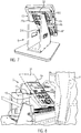
- Figure 4 shows the external control stand 5 from a view from below.
- the control panel 6 has an underside 19 via which the control panel 6 is fastened to the holder 13.
- An underground radiator 20 is provided on the underside 19 of the control panel 6.
- the underground radiator 20 By means of the underground radiator 20, the underground present directly below the control panel 6, in particular a terminating edge of the newly produced road surface B, can be illuminated.
- FIG 4 Also shows Figure 4 a fastening part 21 with which the holder 13 is attached to the mounting tube 17.
- the fastening part 21 is designed to mount the holder 13 in a height-adjustable manner and to be able to rotate around the longitudinal axis of the mounting tube 17.
- Figure 5 shows a part of the holder 13 of the external operator 5.
- a first plug connector part 22 with a first electrical contact part 23 formed integrally thereon is shown on the holder 13.
- Two parallel guide rails 24 are formed on the first connector part 22.
- the two guide rails 24 form a linear guide 25 on the holder 13.
- the linear guide 25 comprises a lighting unit 35 for illuminating the respective guide rails 24.
- FIG. 5 to see a protective flap 26, which is assigned to the first electrical contact part 23.
- the first electrical contact part 23 can be covered by means of the protective flap 26 in order to avoid the effects of the weather and contamination of the first electrical contact part 23.
- a seal 36 running all around it.
- the first plug connector part 22 provided on the holder 13 is designed as part of a plug connection device 27 which is used when the control panel 6 is attached to and removed from the holder 13.
- the connector device 27 is made up of the first connector part 22 together with the now in connection with Figure 6
- the second connector part 28 described is designed in order to be able to fasten the control panel 6 to the holder 13 of the external control stand 5 in a simple manner.
- the illustrated second connector part 28 of the connector device 27 has a second electrical contact part 29 which is formed integrally thereon and which can be plugged into the first electrical contact part 23 and which makes contact with the first electrical contact part 23 of the first connector part 22 to produce an electrical coupling Figure 5 is dockable.
- the second connector part 28 is formed on the underside 19 of the control panel 6.
- the connector device 27 has two parallel mounting rails 30 on the second connector part 28, which together with the in Figure 5
- the guide rails 24 shown form the linear guide 25.
- two laterally displaceably mounted handles 11 are shown on the underside 19 of the control panel 6, which can be manually operated by the operator to attach and detach the control panel 6 on the holder 13.
- the two handles 11 each include a locking projection 31, with which the control panel 6 can be secured to the holder 13, in particular to the first plug connector part 22 formed thereon, and in particular can be electrically coupled with a preloaded pressure.
- Figure 7 shows a schematic rear view of an outside control station 5 of the screed 3 with two separately designed control panels 6a, 6b attached to it.
- a connector device 27a, 27b formed separately on the holder 13 is provided in order to releasably attach the respective control panels 6a, 6b to the external control station 5.
- Figure 7 also shows that the two control panels 6a, 6b are arranged one above the other in a common, schematically indicated assembly plane 32 on the holder 13.
- the two control panels 6a, 6b can be attached to the holder 13 in opposite installation directions M1, M2 and dismantled in the opposite direction.
- Figure 8 shows an external control station 5 in a schematic perspective illustration with two control panels 6a, 6b which are fastened one above the other to the holder 13 along the assembly plane 32 and which are arranged as separate operating modules on the holder 13.
- An operator F is positioned behind the external control stand 5.
- the respective control panels 6a, 6b can be removed separately from the holder 13 by the operator F as an input unit in order to be used as a mobile input unit in the area of the paver 1, in particular in the area of the screed 3, if necessary.
- Figure 9 shows a holder 13 for attaching two separately designed control panels 6a, 6b.
- first plug connector parts 22a, 22b for attaching the respective control panels 6a, 6b are formed one above the other.
- Figure 9 also shows that the base plate 18 is attached to an upper part 34 of the bracket 13 by means of a pivot connection 33. With the aid of the pivot connection 33, the base plate 18 can be adjusted to a desired inclined orientation in order to align the control panels 6a, 6b attached to the holder 13.
- Figure 10 shows the in Figure 9 free holder 13 shown with an operating panel 6a fastened to the upper first plug connector part 22a.
- connection with the plug-in connection device can be used both on an external control station for attaching one as well as for attaching several separate control panels. Regardless of whether an external control stand with just one control panel or with several control panels is used on the screed, the control panels can be easily attached to or removed from the external control stand by means of the connector device according to the invention, both mechanically and electrically, using a single coupling process .
Landscapes
- Engineering & Computer Science (AREA)
- Architecture (AREA)
- Civil Engineering (AREA)
- Structural Engineering (AREA)
- Mechanical Engineering (AREA)
- Road Paving Machines (AREA)
Priority Applications (7)
| Application Number | Priority Date | Filing Date | Title |
|---|---|---|---|
| EP19173275.9A EP3736378B1 (de) | 2019-05-08 | 2019-05-08 | Einbaubohle mit schnellkupplung für aussenbedienstand |
| PL19173275T PL3736378T3 (pl) | 2019-05-08 | 2019-05-08 | Deska równająca z szybkozłączem dla zewnętrznego stanowiska obsługi |
| JP2020081124A JP6998989B2 (ja) | 2019-05-08 | 2020-05-01 | 外部制御ステーションのためのクイックカップリングを備えた舗装スクリード |
| BR102020009081-0A BR102020009081B1 (pt) | 2019-05-08 | 2020-05-07 | Mesa de pavimentação e finalizadora de estradas |
| CN202010375890.XA CN111910493B (zh) | 2019-05-08 | 2020-05-07 | 具有用于外部控制站的快速联接器的摊铺熨平板 |
| CN202020728690.3U CN212956049U (zh) | 2019-05-08 | 2020-05-07 | 用于压实摊铺物料的摊铺熨平板和道路整修机 |
| US16/870,102 US11447077B2 (en) | 2019-05-08 | 2020-05-08 | Paving screed with quick coupling for external control station |
Applications Claiming Priority (1)
| Application Number | Priority Date | Filing Date | Title |
|---|---|---|---|
| EP19173275.9A EP3736378B1 (de) | 2019-05-08 | 2019-05-08 | Einbaubohle mit schnellkupplung für aussenbedienstand |
Publications (2)
| Publication Number | Publication Date |
|---|---|
| EP3736378A1 EP3736378A1 (de) | 2020-11-11 |
| EP3736378B1 true EP3736378B1 (de) | 2021-05-05 |
Family
ID=66597485
Family Applications (1)
| Application Number | Title | Priority Date | Filing Date |
|---|---|---|---|
| EP19173275.9A Active EP3736378B1 (de) | 2019-05-08 | 2019-05-08 | Einbaubohle mit schnellkupplung für aussenbedienstand |
Country Status (5)
| Country | Link |
|---|---|
| US (1) | US11447077B2 (ja) |
| EP (1) | EP3736378B1 (ja) |
| JP (1) | JP6998989B2 (ja) |
| CN (2) | CN111910493B (ja) |
| PL (1) | PL3736378T3 (ja) |
Families Citing this family (2)
| Publication number | Priority date | Publication date | Assignee | Title |
|---|---|---|---|---|
| PL3736378T3 (pl) * | 2019-05-08 | 2021-11-15 | Joseph Vögele AG | Deska równająca z szybkozłączem dla zewnętrznego stanowiska obsługi |
| PL3916156T3 (pl) * | 2020-05-29 | 2024-05-27 | Joseph Vögele AG | Wykańczarka z jednostką obsługową |
Family Cites Families (36)
| Publication number | Priority date | Publication date | Assignee | Title |
|---|---|---|---|---|
| US4969830A (en) * | 1989-06-12 | 1990-11-13 | Grid Systems Corporation | Connection between portable computer components |
| JP2547786Y2 (ja) * | 1991-04-12 | 1997-09-17 | パイオニア株式会社 | グリル着脱装置 |
| JPH04328284A (ja) * | 1991-04-26 | 1992-11-17 | Mitsubishi Electric Corp | コネクタ |
| US5323291A (en) * | 1992-10-15 | 1994-06-21 | Apple Computer, Inc. | Portable computer and docking station having an electromechanical docking/undocking mechanism and a plurality of cooperatively interacting failsafe mechanisms |
| US6504710B2 (en) * | 1998-11-27 | 2003-01-07 | Xplore Technologies Corp. | Method of interconnecting of a hand-held auxiliary unit, a portable computer and a peripheral device |
| US6276613B1 (en) * | 1999-02-22 | 2001-08-21 | Alto Us, Inc. | Chemical foaming system for floor cleaning machine |
| US6594146B2 (en) * | 2000-12-26 | 2003-07-15 | Ge Medical Systems Information Technologies, Inc. | Docking station for patient monitor or other electronic device |
| EP1550360A1 (en) * | 2002-05-28 | 2005-07-06 | Eric Thompson | Vertical docking station |
| US7209124B2 (en) * | 2002-08-08 | 2007-04-24 | Hewlett-Packard Development Company, L.P. | Multiple-position docking station for a tablet personal computer |
| EP1627774B1 (de) * | 2004-07-27 | 2007-09-12 | Joseph Voegele AG | Baumaschine mit Bedienkonsole |
| US7172363B2 (en) * | 2004-08-31 | 2007-02-06 | Caterpillar Paving Products Inc | Paving machine output monitoring system |
| EP1754831B1 (de) * | 2005-08-17 | 2011-10-12 | Joseph Vögele AG | Strassenfertiger und Datenspeichervorrichtung |
| DE102008047339B3 (de) * | 2008-09-15 | 2010-03-04 | Celon Ag Medical Instruments | Medizintechnisches Gerät und medizintechnische Geräteanordnung |
| JP2011156895A (ja) * | 2010-01-29 | 2011-08-18 | Fujitsu Ten Ltd | ミラー装置、および、ミラーシステム |
| PL2372022T3 (pl) * | 2010-03-23 | 2015-06-30 | Joseph Voegele Ag | Maszyna do budowy dróg |
| PL2578748T3 (pl) * | 2011-10-04 | 2019-01-31 | Joseph Vögele AG | Zewnętrzne stanowisko sterowania dla maszyny budowlanej |
| JP2013091342A (ja) * | 2011-10-24 | 2013-05-16 | Clarion Co Ltd | 車載用音響装置 |
| US8873233B2 (en) * | 2011-10-28 | 2014-10-28 | Xplore Technologies Corp. | Vehicle dock for ruggedized tablet |
| DE202012003217U1 (de) * | 2012-03-29 | 2013-07-01 | Joseph Vögele AG | Außensteuerstand für eine Baumaschine |
| DE202012003790U1 (de) | 2012-04-13 | 2013-07-17 | Joseph Vögele AG | Straßenfertiger mit verstellbarem Bedienpult |
| EP2696173A1 (de) * | 2012-08-10 | 2014-02-12 | Joseph Vögele AG | Baumaschine mit Sensoreinheit |
| US9298661B2 (en) * | 2012-12-21 | 2016-03-29 | Technologies Humanware Inc. | Docking assembly with a reciprocally movable handle for docking a handheld device |
| US9268376B2 (en) * | 2013-01-09 | 2016-02-23 | Google Technology Holdings LLC | Mobile computing device dock station with headset jack heat pipe interface |
| US9690729B2 (en) * | 2013-02-01 | 2017-06-27 | Audi Ag | Tablet computer dock |
| CN104035341A (zh) * | 2013-03-05 | 2014-09-10 | 李文庆 | 一种家电的外挂式控制机构 |
| US8961064B2 (en) * | 2013-04-01 | 2015-02-24 | Caterpillar Paving Products Inc. | System and method for screed extension identification |
| SE540658C2 (sv) * | 2013-07-31 | 2018-10-09 | Vaederstad Holding Ab | Hållare för en surfplatta |
| EP2837739B1 (de) | 2013-08-16 | 2017-06-14 | Joseph Vögele AG | Straßenfertiger mit Schubvorrichtung |
| DE102015006250B4 (de) * | 2014-05-20 | 2021-03-25 | Bomag Gmbh | Anbaubohleneinheit für einen Straßenfertiger und Straßenfertiger mit einer solchen Anbaubohleneinheit |
| US9434319B2 (en) * | 2015-01-07 | 2016-09-06 | Ford Global Technologies, Llc | Personal electronic device dock |
| PL3067774T3 (pl) * | 2015-03-13 | 2018-07-31 | Voegele Ag J | Urządzenie operacyjne do maszyny budowlanej |
| EP3075909B1 (de) * | 2015-03-30 | 2017-09-06 | Joseph Vögele AG | Strassenbaumaschine mit netzwerk zur datenübertragung und verwendung eines teils einer stromleitung |
| CN111344458A (zh) * | 2017-08-01 | 2020-06-26 | 住友建机株式会社 | 沥青滚平机 |
| CN207625634U (zh) * | 2017-12-27 | 2018-07-17 | 深圳市新庄谷德科技有限公司 | 一种手机支架 |
| EP3578716B1 (de) * | 2018-06-06 | 2020-09-16 | Joseph Vögele AG | Fernbedienungshalter für einen strassenfertiger |
| PL3736378T3 (pl) | 2019-05-08 | 2021-11-15 | Joseph Vögele AG | Deska równająca z szybkozłączem dla zewnętrznego stanowiska obsługi |
-
2019
- 2019-05-08 PL PL19173275T patent/PL3736378T3/pl unknown
- 2019-05-08 EP EP19173275.9A patent/EP3736378B1/de active Active
-
2020
- 2020-05-01 JP JP2020081124A patent/JP6998989B2/ja active Active
- 2020-05-07 CN CN202010375890.XA patent/CN111910493B/zh active Active
- 2020-05-07 CN CN202020728690.3U patent/CN212956049U/zh not_active Withdrawn - After Issue
- 2020-05-08 US US16/870,102 patent/US11447077B2/en active Active
Also Published As
| Publication number | Publication date |
|---|---|
| EP3736378A1 (de) | 2020-11-11 |
| BR102020009081A2 (pt) | 2020-11-17 |
| CN111910493B (zh) | 2022-08-16 |
| US20200353874A1 (en) | 2020-11-12 |
| US11447077B2 (en) | 2022-09-20 |
| CN212956049U (zh) | 2021-04-13 |
| PL3736378T3 (pl) | 2021-11-15 |
| CN111910493A (zh) | 2020-11-10 |
| JP2020183698A (ja) | 2020-11-12 |
| JP6998989B2 (ja) | 2022-01-18 |
Similar Documents
| Publication | Publication Date | Title |
|---|---|---|
| DE102014224560B4 (de) | Anordnung für einen Fahrzeuginnenraum, Kraftfahrzeug | |
| DE3785698T2 (de) | Vorrichtung zum verlegen eines kabels in einem rohr. | |
| EP3736378B1 (de) | Einbaubohle mit schnellkupplung für aussenbedienstand | |
| EP2650197B1 (de) | Straßenfertiger sowie Sitzkonsole | |
| EP1892514A2 (de) | Vorrichtung zur Halterung eines Fahrroboters | |
| DE102006008216B4 (de) | Vorrichtung und Verfahren zur lagegenauen Positionierung zumindest einer Fahrzeugkomponente an einem Fahrzeug | |
| EP1075350A1 (de) | Führungswagen für ein von hand führbares arbeitsgerät, insbesondere für einen trennschleifer | |
| EP1522633B1 (de) | Strassenfräsmaschine mit Lenkeinrichtung | |
| WO2014076096A1 (de) | Bedieneinheit für ein medizingerät | |
| EP0917867B1 (de) | Zusatzmodul für einen Operationstisch | |
| DE3840801A1 (de) | Deichsel fuer von hand gefuehrte hubwagen und -lader | |
| DE202005018633U1 (de) | Einstellbare Halteeinrichtung für von rückseitigen Passagieren bedienbare Bordcomputer in Kraftfahrzeugen, insbesondere für Laptop- oder Notebook-Computer | |
| EP2248504B1 (de) | Medizinische Versorgungseinheit mit Einbaumodulen | |
| EP3382098B1 (de) | Strassenfertiger mit haltevorrichtung zum tragen und positionieren einer sensoreinheit | |
| EP0422489A1 (de) | Kraftfahrzeug mit kippbarer Kabine und Kippvorrichtung | |
| EP0086954A2 (de) | Werkzeug zum Herausziehen eines Elektronikeinschubes aus einem Haltegestell | |
| DE102019125553A1 (de) | Bewegliche bedienerstation für verbesserte sicht | |
| EP3768564A1 (de) | Modulares fusspodest für einen führerstand eines schienenfahrzeugs | |
| WO2017055220A1 (de) | Selbstfahrende maschine, und positioniervorrichtung für eine bediener-armatureneinheit an einer selbstfahrenden maschine | |
| EP1034927A1 (de) | Einrichtung zur Qualitätskontrolle für eine Bogendruckmaschine | |
| DE102012016021A1 (de) | Strassenbaumaschine | |
| EP1592607A1 (de) | Lastkraftwagen | |
| DE1282046B (de) | Vorrichtung zum Kuppeln eines Geraetes fuer den Strassendienst, z. B. eines Schneeraeumgeraets, mit einem Kraftfahrzeug | |
| EP4117969B1 (de) | Armaturenbrett für ein fahrzeug, fahrzeug mit dem armaturenbrett und halteeinrichtung zum halten eines mobilen geräts zur verwendung in dem armaturenbrett | |
| EP1880634B1 (de) | Tisch mit einer Arbeitstischplatte und einer Bildschirmtischplatte |
Legal Events
| Date | Code | Title | Description |
|---|---|---|---|
| STAA | Information on the status of an ep patent application or granted ep patent |
Free format text: STATUS: EXAMINATION IS IN PROGRESS |
|
| PUAI | Public reference made under article 153(3) epc to a published international application that has entered the european phase |
Free format text: ORIGINAL CODE: 0009012 |
|
| 17P | Request for examination filed |
Effective date: 20200311 |
|
| AK | Designated contracting states |
Kind code of ref document: A1 Designated state(s): AL AT BE BG CH CY CZ DE DK EE ES FI FR GB GR HR HU IE IS IT LI LT LU LV MC MK MT NL NO PL PT RO RS SE SI SK SM TR |
|
| AX | Request for extension of the european patent |
Extension state: BA ME |
|
| GRAP | Despatch of communication of intention to grant a patent |
Free format text: ORIGINAL CODE: EPIDOSNIGR1 |
|
| STAA | Information on the status of an ep patent application or granted ep patent |
Free format text: STATUS: GRANT OF PATENT IS INTENDED |
|
| INTG | Intention to grant announced |
Effective date: 20201203 |
|
| GRAS | Grant fee paid |
Free format text: ORIGINAL CODE: EPIDOSNIGR3 |
|
| GRAA | (expected) grant |
Free format text: ORIGINAL CODE: 0009210 |
|
| STAA | Information on the status of an ep patent application or granted ep patent |
Free format text: STATUS: THE PATENT HAS BEEN GRANTED |
|
| AK | Designated contracting states |
Kind code of ref document: B1 Designated state(s): AL AT BE BG CH CY CZ DE DK EE ES FI FR GB GR HR HU IE IS IT LI LT LU LV MC MK MT NL NO PL PT RO RS SE SI SK SM TR |
|
| REG | Reference to a national code |
Ref country code: GB Ref legal event code: FG4D Free format text: NOT ENGLISH |
|
| REG | Reference to a national code |
Ref country code: CH Ref legal event code: EP |
|
| REG | Reference to a national code |
Ref country code: AT Ref legal event code: REF Ref document number: 1389961 Country of ref document: AT Kind code of ref document: T Effective date: 20210515 |
|
| REG | Reference to a national code |
Ref country code: IE Ref legal event code: FG4D Free format text: LANGUAGE OF EP DOCUMENT: GERMAN |
|
| REG | Reference to a national code |
Ref country code: DE Ref legal event code: R096 Ref document number: 502019001350 Country of ref document: DE |
|
| REG | Reference to a national code |
Ref country code: LT Ref legal event code: MG9D |
|
| PG25 | Lapsed in a contracting state [announced via postgrant information from national office to epo] |
Ref country code: LT Free format text: LAPSE BECAUSE OF FAILURE TO SUBMIT A TRANSLATION OF THE DESCRIPTION OR TO PAY THE FEE WITHIN THE PRESCRIBED TIME-LIMIT Effective date: 20210505 Ref country code: HR Free format text: LAPSE BECAUSE OF FAILURE TO SUBMIT A TRANSLATION OF THE DESCRIPTION OR TO PAY THE FEE WITHIN THE PRESCRIBED TIME-LIMIT Effective date: 20210505 Ref country code: FI Free format text: LAPSE BECAUSE OF FAILURE TO SUBMIT A TRANSLATION OF THE DESCRIPTION OR TO PAY THE FEE WITHIN THE PRESCRIBED TIME-LIMIT Effective date: 20210505 Ref country code: BG Free format text: LAPSE BECAUSE OF FAILURE TO SUBMIT A TRANSLATION OF THE DESCRIPTION OR TO PAY THE FEE WITHIN THE PRESCRIBED TIME-LIMIT Effective date: 20210805 |
|
| PG25 | Lapsed in a contracting state [announced via postgrant information from national office to epo] |
Ref country code: IS Free format text: LAPSE BECAUSE OF FAILURE TO SUBMIT A TRANSLATION OF THE DESCRIPTION OR TO PAY THE FEE WITHIN THE PRESCRIBED TIME-LIMIT Effective date: 20210905 Ref country code: GR Free format text: LAPSE BECAUSE OF FAILURE TO SUBMIT A TRANSLATION OF THE DESCRIPTION OR TO PAY THE FEE WITHIN THE PRESCRIBED TIME-LIMIT Effective date: 20210806 Ref country code: SE Free format text: LAPSE BECAUSE OF FAILURE TO SUBMIT A TRANSLATION OF THE DESCRIPTION OR TO PAY THE FEE WITHIN THE PRESCRIBED TIME-LIMIT Effective date: 20210505 Ref country code: PT Free format text: LAPSE BECAUSE OF FAILURE TO SUBMIT A TRANSLATION OF THE DESCRIPTION OR TO PAY THE FEE WITHIN THE PRESCRIBED TIME-LIMIT Effective date: 20210906 Ref country code: RS Free format text: LAPSE BECAUSE OF FAILURE TO SUBMIT A TRANSLATION OF THE DESCRIPTION OR TO PAY THE FEE WITHIN THE PRESCRIBED TIME-LIMIT Effective date: 20210505 Ref country code: LV Free format text: LAPSE BECAUSE OF FAILURE TO SUBMIT A TRANSLATION OF THE DESCRIPTION OR TO PAY THE FEE WITHIN THE PRESCRIBED TIME-LIMIT Effective date: 20210505 Ref country code: NO Free format text: LAPSE BECAUSE OF FAILURE TO SUBMIT A TRANSLATION OF THE DESCRIPTION OR TO PAY THE FEE WITHIN THE PRESCRIBED TIME-LIMIT Effective date: 20210805 |
|
| REG | Reference to a national code |
Ref country code: NL Ref legal event code: MP Effective date: 20210505 |
|
| PG25 | Lapsed in a contracting state [announced via postgrant information from national office to epo] |
Ref country code: NL Free format text: LAPSE BECAUSE OF FAILURE TO SUBMIT A TRANSLATION OF THE DESCRIPTION OR TO PAY THE FEE WITHIN THE PRESCRIBED TIME-LIMIT Effective date: 20210505 |
|
| PG25 | Lapsed in a contracting state [announced via postgrant information from national office to epo] |
Ref country code: DK Free format text: LAPSE BECAUSE OF FAILURE TO SUBMIT A TRANSLATION OF THE DESCRIPTION OR TO PAY THE FEE WITHIN THE PRESCRIBED TIME-LIMIT Effective date: 20210505 Ref country code: CZ Free format text: LAPSE BECAUSE OF FAILURE TO SUBMIT A TRANSLATION OF THE DESCRIPTION OR TO PAY THE FEE WITHIN THE PRESCRIBED TIME-LIMIT Effective date: 20210505 Ref country code: LU Free format text: LAPSE BECAUSE OF NON-PAYMENT OF DUE FEES Effective date: 20210508 Ref country code: RO Free format text: LAPSE BECAUSE OF FAILURE TO SUBMIT A TRANSLATION OF THE DESCRIPTION OR TO PAY THE FEE WITHIN THE PRESCRIBED TIME-LIMIT Effective date: 20210505 Ref country code: SM Free format text: LAPSE BECAUSE OF FAILURE TO SUBMIT A TRANSLATION OF THE DESCRIPTION OR TO PAY THE FEE WITHIN THE PRESCRIBED TIME-LIMIT Effective date: 20210505 Ref country code: SK Free format text: LAPSE BECAUSE OF FAILURE TO SUBMIT A TRANSLATION OF THE DESCRIPTION OR TO PAY THE FEE WITHIN THE PRESCRIBED TIME-LIMIT Effective date: 20210505 Ref country code: ES Free format text: LAPSE BECAUSE OF FAILURE TO SUBMIT A TRANSLATION OF THE DESCRIPTION OR TO PAY THE FEE WITHIN THE PRESCRIBED TIME-LIMIT Effective date: 20210505 Ref country code: EE Free format text: LAPSE BECAUSE OF FAILURE TO SUBMIT A TRANSLATION OF THE DESCRIPTION OR TO PAY THE FEE WITHIN THE PRESCRIBED TIME-LIMIT Effective date: 20210505 |
|
| REG | Reference to a national code |
Ref country code: DE Ref legal event code: R097 Ref document number: 502019001350 Country of ref document: DE |
|
| REG | Reference to a national code |
Ref country code: BE Ref legal event code: MM Effective date: 20210531 |
|
| PLBE | No opposition filed within time limit |
Free format text: ORIGINAL CODE: 0009261 |
|
| STAA | Information on the status of an ep patent application or granted ep patent |
Free format text: STATUS: NO OPPOSITION FILED WITHIN TIME LIMIT |
|
| PG25 | Lapsed in a contracting state [announced via postgrant information from national office to epo] |
Ref country code: MC Free format text: LAPSE BECAUSE OF FAILURE TO SUBMIT A TRANSLATION OF THE DESCRIPTION OR TO PAY THE FEE WITHIN THE PRESCRIBED TIME-LIMIT Effective date: 20210505 |
|
| 26N | No opposition filed |
Effective date: 20220208 |
|
| PG25 | Lapsed in a contracting state [announced via postgrant information from national office to epo] |
Ref country code: IE Free format text: LAPSE BECAUSE OF NON-PAYMENT OF DUE FEES Effective date: 20210508 |
|
| PG25 | Lapsed in a contracting state [announced via postgrant information from national office to epo] |
Ref country code: IS Free format text: LAPSE BECAUSE OF FAILURE TO SUBMIT A TRANSLATION OF THE DESCRIPTION OR TO PAY THE FEE WITHIN THE PRESCRIBED TIME-LIMIT Effective date: 20210905 Ref country code: AL Free format text: LAPSE BECAUSE OF FAILURE TO SUBMIT A TRANSLATION OF THE DESCRIPTION OR TO PAY THE FEE WITHIN THE PRESCRIBED TIME-LIMIT Effective date: 20210505 |
|
| PG25 | Lapsed in a contracting state [announced via postgrant information from national office to epo] |
Ref country code: BE Free format text: LAPSE BECAUSE OF NON-PAYMENT OF DUE FEES Effective date: 20210531 |
|
| REG | Reference to a national code |
Ref country code: CH Ref legal event code: PL |
|
| PG25 | Lapsed in a contracting state [announced via postgrant information from national office to epo] |
Ref country code: LI Free format text: LAPSE BECAUSE OF NON-PAYMENT OF DUE FEES Effective date: 20220531 Ref country code: CH Free format text: LAPSE BECAUSE OF NON-PAYMENT OF DUE FEES Effective date: 20220531 |
|
| P01 | Opt-out of the competence of the unified patent court (upc) registered |
Effective date: 20230524 |
|
| PG25 | Lapsed in a contracting state [announced via postgrant information from national office to epo] |
Ref country code: CY Free format text: LAPSE BECAUSE OF FAILURE TO SUBMIT A TRANSLATION OF THE DESCRIPTION OR TO PAY THE FEE WITHIN THE PRESCRIBED TIME-LIMIT Effective date: 20210505 |
|
| PG25 | Lapsed in a contracting state [announced via postgrant information from national office to epo] |
Ref country code: HU Free format text: LAPSE BECAUSE OF FAILURE TO SUBMIT A TRANSLATION OF THE DESCRIPTION OR TO PAY THE FEE WITHIN THE PRESCRIBED TIME-LIMIT; INVALID AB INITIO Effective date: 20190508 |
|
| PG25 | Lapsed in a contracting state [announced via postgrant information from national office to epo] |
Ref country code: MK Free format text: LAPSE BECAUSE OF FAILURE TO SUBMIT A TRANSLATION OF THE DESCRIPTION OR TO PAY THE FEE WITHIN THE PRESCRIBED TIME-LIMIT Effective date: 20210505 |
|
| PG25 | Lapsed in a contracting state [announced via postgrant information from national office to epo] |
Ref country code: TR Free format text: LAPSE BECAUSE OF FAILURE TO SUBMIT A TRANSLATION OF THE DESCRIPTION OR TO PAY THE FEE WITHIN THE PRESCRIBED TIME-LIMIT Effective date: 20210505 |
|
| PGFP | Annual fee paid to national office [announced via postgrant information from national office to epo] |
Ref country code: GB Payment date: 20240516 Year of fee payment: 6 |
|
| PGFP | Annual fee paid to national office [announced via postgrant information from national office to epo] |
Ref country code: DE Payment date: 20240527 Year of fee payment: 6 |
|
| PGFP | Annual fee paid to national office [announced via postgrant information from national office to epo] |
Ref country code: FR Payment date: 20240522 Year of fee payment: 6 |
|
| PGFP | Annual fee paid to national office [announced via postgrant information from national office to epo] |
Ref country code: PL Payment date: 20240510 Year of fee payment: 6 |
|
| PG25 | Lapsed in a contracting state [announced via postgrant information from national office to epo] |
Ref country code: MT Free format text: LAPSE BECAUSE OF FAILURE TO SUBMIT A TRANSLATION OF THE DESCRIPTION OR TO PAY THE FEE WITHIN THE PRESCRIBED TIME-LIMIT Effective date: 20210505 |
|
| PGFP | Annual fee paid to national office [announced via postgrant information from national office to epo] |
Ref country code: IT Payment date: 20240529 Year of fee payment: 6 |