EP3734247A1 - Load sensor and load sensor-integrated multi-axis actuator - Google Patents
Load sensor and load sensor-integrated multi-axis actuator Download PDFInfo
- Publication number
- EP3734247A1 EP3734247A1 EP18896699.8A EP18896699A EP3734247A1 EP 3734247 A1 EP3734247 A1 EP 3734247A1 EP 18896699 A EP18896699 A EP 18896699A EP 3734247 A1 EP3734247 A1 EP 3734247A1
- Authority
- EP
- European Patent Office
- Prior art keywords
- shaft
- coupling part
- coupling
- load sensor
- drive rod
- Prior art date
- Legal status (The legal status is an assumption and is not a legal conclusion. Google has not performed a legal analysis and makes no representation as to the accuracy of the status listed.)
- Ceased
Links
Images


Classifications
-
- G—PHYSICS
- G01—MEASURING; TESTING
- G01L—MEASURING FORCE, STRESS, TORQUE, WORK, MECHANICAL POWER, MECHANICAL EFFICIENCY, OR FLUID PRESSURE
- G01L1/00—Measuring force or stress, in general
- G01L1/20—Measuring force or stress, in general by measuring variations in ohmic resistance of solid materials or of electrically-conductive fluids; by making use of electrokinetic cells, i.e. liquid-containing cells wherein an electrical potential is produced or varied upon the application of stress
- G01L1/22—Measuring force or stress, in general by measuring variations in ohmic resistance of solid materials or of electrically-conductive fluids; by making use of electrokinetic cells, i.e. liquid-containing cells wherein an electrical potential is produced or varied upon the application of stress using resistance strain gauges
- G01L1/2206—Special supports with preselected places to mount the resistance strain gauges; Mounting of supports
-
- G—PHYSICS
- G01—MEASURING; TESTING
- G01L—MEASURING FORCE, STRESS, TORQUE, WORK, MECHANICAL POWER, MECHANICAL EFFICIENCY, OR FLUID PRESSURE
- G01L5/00—Apparatus for, or methods of, measuring force, work, mechanical power, or torque, specially adapted for specific purposes
- G01L5/0028—Force sensors associated with force applying means
- G01L5/0038—Force sensors associated with force applying means applying a pushing force
-
- G—PHYSICS
- G01—MEASURING; TESTING
- G01L—MEASURING FORCE, STRESS, TORQUE, WORK, MECHANICAL POWER, MECHANICAL EFFICIENCY, OR FLUID PRESSURE
- G01L5/00—Apparatus for, or methods of, measuring force, work, mechanical power, or torque, specially adapted for specific purposes
- G01L5/0061—Force sensors associated with industrial machines or actuators
- G01L5/0076—Force sensors associated with manufacturing machines
-
- H—ELECTRICITY
- H05—ELECTRIC TECHNIQUES NOT OTHERWISE PROVIDED FOR
- H05K—PRINTED CIRCUITS; CASINGS OR CONSTRUCTIONAL DETAILS OF ELECTRIC APPARATUS; MANUFACTURE OF ASSEMBLAGES OF ELECTRICAL COMPONENTS
- H05K13/00—Apparatus or processes specially adapted for manufacturing or adjusting assemblages of electric components
- H05K13/04—Mounting of components, e.g. of leadless components
-
- H—ELECTRICITY
- H05—ELECTRIC TECHNIQUES NOT OTHERWISE PROVIDED FOR
- H05K—PRINTED CIRCUITS; CASINGS OR CONSTRUCTIONAL DETAILS OF ELECTRIC APPARATUS; MANUFACTURE OF ASSEMBLAGES OF ELECTRICAL COMPONENTS
- H05K13/00—Apparatus or processes specially adapted for manufacturing or adjusting assemblages of electric components
- H05K13/04—Mounting of components, e.g. of leadless components
- H05K13/0404—Pick-and-place heads or apparatus, e.g. with jaws
- H05K13/0408—Incorporating a pick-up tool
- H05K13/0409—Sucking devices
Definitions
- the present invention relates to a load sensor and a load sensor integrated type multiaxial actuator, and, for example, relates to a load sensor that detects, in a multiaxial actuator to be used as a chip mounter that mounts an electronic part (chip) to a substrate, pressing force (load) to the chip in a case where the chip is suctioned and mounted to the substrate in a state where the chip is pressed against a tip end of a shaft-like member formed to be hollow, and a load sensor integrated type multiaxial actuator.
- a linear motor actuator exists as a multiaxial actuator to be incorporated in a chip mounter.
- This linear motor actuator is configured to cause a shaft-like member to perform linear motion in an axial direction by using a linear motor from that linear thrust can be obtained (for example, see Patent Literature 1).
- Patent Literature 1 Japanese Patent Application Publication No. 2014-18072
- a load sensor is a load sensor to be used for a multiaxial actuator that has a first shaft-like member that linearly moves in an axial direction in a state of being contained in a housing, and a second shaft-like member that is arranged in parallel with the first shaft-like member, linearly moves at the same time as the first shaft-like member in the axial direction, and has a tip end portion to be pressed, when a predetermined object is to be suctioned, against the object
- the load sensor includes a coupling member that couples the first shaft-like member and the second shaft-like member, the coupling member has a first coupling part that couples the first shaft-like member, a second coupling part that couples the second shaft-like member, and a neck part that is provided between the first coupling part and the second coupling part and formed to be thinner than the first coupling part and the second coupling part, and the neck part includes a strain gauge attached to a front surface of the neck part.
- the strain gauge is affixed to the front surface facing a direction perpendicular to the axial direction of the first shaft-like member and the second shaft-like member in the neck part.
- the neck part it is preferable for the neck part that a through hole penetrating through the neck part is formed.
- a load sensor integrated type multiaxial actuator includes a first shaft-like member that linearly moves in an axial direction in a state of being contained in a housing, a second shaft-like member that is arranged in parallel with the first shaft-like member, linearly moves at the same time as the first shaft-like member in the axial direction, and has a tip end portion to be pressed, when a predetermined object is to be suctioned, against the object, and a coupling member that couples the first shaft-like member and the second shaft-like member to cause the first shaft-like member and the second shaft-like member to linearly move at the same time in the axial direction
- the coupling member has a first coupling part that couples the first shaft-like member, a second coupling part that couples the second shaft-like member, and a neck part that is provided between the first coupling part and the second coupling part and formed to be thinner than the first coupling part and the second coupling part
- the neck part includes a strain gauge attached to a front surface of the neck part
- Fig. 1 is an external perspective view showing an entire configuration of a load sensor integrated type multiaxial actuator according to an embodiment of the present invention.
- Fig. 2 is a schematic enlarged perspective view showing an external configuration of a coupling member according to the embodiment of the present invention.
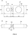
- Figs. 3 are a plan view and a side view showing the external configuration of the coupling member according to the embodiment of the present invention.
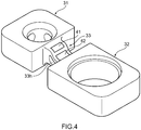
- Fig. 4 is an enlarged perspective view showing a state where a neck part of the coupling member is bent according to the embodiment of the present invention.
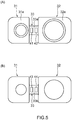
- Figs. 5 are plan views showing an arrangement of strain gauges affixed to the neck part of the coupling member according to the embodiment of the present invention.
- a load sensor integrated type multiaxial actuator 10 is used by being incorporated in a chip mounter that mounts an object such as an electronic part (chip) onto a substrate.
- the load sensor integrated type multiaxial actuator 10 mainly includes, for example, a housing 11 having a three-phase motor (not shown) built therein, a drive rod 12 serving as a first shaft-like member that linearly moves relatively in an axial direction by the three-phase motor, a suction rod 22 that is arranged in parallel with the drive rod 12 and serves as a second shaft-like member that suctions a chip at a tip end portion, and a coupling member 30 that integrally couples the drive rod 12 and the suction rod 22 on a tip end side and also serves as a load sensor that can detect a load when a chip is pressed against a tip end of the suction rod 22.
- the housing 11 is a package that has the above-mentioned three-phase motor built therein and is made of a metal, resin, or the like, and holds the drive rod 12 in a state where the drive rod 12 is allowed to linearly move relatively along the axial direction. It is noted that the housing 11 holds the drive rod 12 via a holding plate 24 (which will be described below).
- a three-phase coil (not shown) constituted by a U phase, a V phase, and a W phase in the surrounding of the drive rod 12 is arranged, and when a current flows through the three-phase coil, the drive rod 12 linearly moves in the axial direction relative to the housing 11.
- the drive rod 12 is a columnar bar-like member made of a metal, resin, or the like extending along the axial direction, and linearly moves in a predetermined stroke range in a state of being held in the housing 11 via the holding plate 24.
- the suction rod 22 is a hollow cylindrical member made of a metal, resin, or the like extending along the axial direction, and is arranged in parallel with the drive rod 12, when a chip is to be suctioned, a tip end portion 22a is pressed against the chip.
- the suction rod 22 is attached to a casing 26 via the holding plate 24.
- An external diameter of the suction rod 22 has a dimension according to a size of a chip, and is smaller than the drive rod 12. It is however noted that the configuration is not limited to this, and the external diameter of the suction rod 22 may be larger than an external diameter of the drive rod 12, and may also be substantially the same.
- This suction rod 22 is connected to a vacuum pump or the like that is not shown in the drawing via a hose or the like.
- a suction pad (not shown) to suction a chip may be attached to the tip end portion 22a of the suction rod 22.
- the casing 26 is made of a metal, resin, or the like, and in the casing 26, a through hole 26a is formed to support the suction rod 22 in such a way as to freely move relatively in the axial direction.
- the casing 26 supports the suction rod 22 such that the suction rod 22 can move in the axial direction along with the motion of the drive rod 12 in the axial direction.
- the holding plate 24 has a cuboid shape which is made of a metal, resin, or the like, and is integrally attached to both the housing 11 and the casing 26.
- the holding plate 24 supports the drive rod 12 and the suction rod 22 such that the drive rod 12 and the suction rod 22 can move in the axial direction, and also suppresses turning of the suction rod 22 about the drive rod 12 in a state where a mutual positional relationship is held.
- the coupling member 30 is a plate-like member having a substantially cuboid shape which couples and fixes the tip end portion of the drive rod 12 and the tip end portion of the suction rod 22 and is made of a metal, resin, or the like.
- the coupling member 30 prevents the drive rod 12 from relatively moving in the axial direction relative to the coupling member 30, and also prevents the suction rod 22 from relatively moving in the axial direction relative to the coupling member 30.
- the coupling member 30 includes a drive rod coupling part 31 serving as a first coupling part which integrally couples and fixes the tip end portion of the drive rod 12 at a front surface 31a thereof, a suction rod coupling part 32 serving as a second coupling part which integrally couples and fixes the suction rod 22 in a state where the suction rod 22 penetrates through from a front surface 32a thereof, and a neck part 33 that integrally links the drive rod coupling part 31 and the suction rod coupling part 32, and these are integrally formed.
- the drive rod coupling part 31 is a part of the coupling member 30 which is located on an extended line of the axial direction of the drive rod 12.
- the suction rod coupling part 32 is a part of the coupling member 30 which is located on an extended line of the axial direction of the suction rod 22.
- the neck part 33 is a part of the coupling member 30 which integrally links the drive rod coupling part 31 and the suction rod coupling part 32, is not located on the extended lines of the axial directions of the drive rod 12 and the suction rod 22, and extends in a direction perpendicular to the axial direction.
- This coupling member 30 can be formed by injection molding or cutting.
- the drive rod coupling part 31 is a fixing part that has a substantially cubic shape and fixes the tip end portion of the drive rod 12.
- the fixing method can be based on various methods such as screw fixing and engagement by interference fit.
- the suction rod coupling part 32 is a fixing part that has a substantially cuboid shape and fixes the tip end portion 22a of the suction rod 22 in a penetrating state.
- the fixing method is similar to the drive rod coupling part 31, and can be based on various methods such as screw fixing and engagement by interference fit.
- the neck part 33 is a neck-like member that has a thickness thinner than the drive rod coupling part 31 and the suction rod coupling part 32, and links the drive rod coupling part 31 and the suction rod coupling part 32.
- a longitudinal direction of the coupling member 30 is set as a length L
- a short direction of the coupling member 30 is set as a width W
- the axial direction of the drive rod 12 and the suction rod 22 of the coupling member 30 is set as a height T, and descriptions will be hereinafter provided.
- a length L3 of the neck part 33 is shorter than a length L1 of the drive rod coupling part 31 and a length L2 of the suction rod coupling part 32.
- a width W3 of the neck part 33 is shorter than a width W1 of the drive rod coupling part 31 and a width W2 of the suction rod coupling part 32.
- a height T3 of the neck part 33 is lower than a height T1 of the drive rod coupling part 31 and a height T2 of the suction rod coupling part 32. Furthermore, the neck part 33 has a through hole 33h having a predetermined inner diameter along a width direction perpendicular to the axial direction of the drive rod 12 and the suction rod 22 on a front surface thereof.
- the neck part 33 is thinner than the drive rod coupling part 31 and the suction rod coupling part 32, and the neck part 33 is also more easily bent than the drive rod coupling part 31 and the suction rod coupling part 32 due to the presence of the through hole 33h.
- strain gauges 41 and 42 are affixed on an upper surface 33a facing an upper direction where the housing 11 and the casing 26 exist, and also strain gauges 43 and 44 are affixed on a lower surface 33b facing a lower direction where a chip as a suction target exists.
- the strain gauges 41 to 44 use a phenomenon where resistance values change when internally arranged resistance elements expand or contract together with a deflection (strain) generated in the neck part 33, and a so-called bridge circuit is constituted.
- a deflection (strain) generated in the neck part 33
- bridge circuit it is possible to measure a load according to a deflection (strain) on the basis of a change of a voltage of the resistance elements of the strain gauges 41 to 44.
- the suction rod 22 in conjunction with pressing-down of the drive rod 12, the suction rod 22 is pressed down together with the coupling member 30, and when the tip end portion 22a of the suction rod 22 is pressed against a chip, reactive force (load) from the chip to the suction rod coupling part 32 becomes a load to the neck part 33.
- the strain gauges 41 to 44 are affixed to these bent parts.
- These bent parts are areas having a thin thickness due to the through hole 33h of the neck part 33, and function as strain body parts.
- the configuration is not limited to only a case where the strain gauges 41 and 42 are affixed to on the upper surface 33a and the strain gauges 43 and 44 are also affixed to on the lower surface 33b, and all of the strain gauges 41 to 44 may also be affixed to either the upper surface 33a or the lower surface 33b.
- the affixation positions of the strain gauges 41 to 44 to the neck part 33 are not particularly limited.
- the number of the strain gauges to be affixed to the neck part 33 does not necessarily need to be four, and at least one may be affixed to either the upper surface 33a or the lower surface 33b.
- the load sensor integrated type multiaxial actuator 10 includes the coupling member 30 serving as a load sensor, and the strain gauges 41 to 44 are affixed to the front surface of the neck part 33 that links the drive rod coupling part 31 and the suction rod coupling part 32 of the coupling member 30 and is thinner than the drive rod coupling part 31 and the suction rod coupling part 32.
- the neck part 33 of the coupling member 30 has rigidity lower than the drive rod coupling part 31 and the suction rod coupling part 32, as has been shown in Fig. 4 , when the tip end portion 22a of the suction rod 22 is pressed against a chip, only the neck part 33 is bent by reactive force (load) from the chip to the suction rod coupling part 32.
- the load sensor integrated type multiaxial actuator 10 can precisely measure pressing force (load) of the suction rod 22 to a chip by the strain gauges 41 to 44 of the coupling member 30.
- the through hole 33h is formed in the neck part 33 of the coupling member 30, but the present invention is not limited to this.
- the through hole 33h does not necessarily need to be formed in the neck part 33.
- the neck part 33 is formed to be thin to such an extent that a deflection occurs earlier than the drive rod coupling part 31 and the suction rod coupling part 32 when reactive force from a chip is applied to the suction rod coupling part 32, the through hole 33h does not necessarily need to be formed.
- the drive rod coupling part 31 is set to have a substantially a cubic shape and the suction rod coupling part 32 is set to have a substantially a cuboid shape, but the configuration is not limited to this, and various other shapes such as a columnar shape may also be adopted as long as the neck part 33 is bent first.
- the length L3 of the neck part 33 is set to be shorter than the length L1 of the drive rod coupling part 31 and the length L2 of the suction rod coupling part 32
- the width W3 of the neck part 33 is set to be shorter than the width W1 of the drive rod coupling part 31 and the width W2 of the suction rod coupling part 32
- the height T3 of the neck part 33 is set to be lower than the height T1 of the drive rod coupling part 31 and the height T2 of the suction rod coupling part 32.
- the present invention is not limited to this, and when the height T3 of the neck part 33 is set to be shorter than the height T1 of the drive rod coupling part 31 and the height T2 of the suction rod coupling part 32, the length L3 of the neck part 33 may also be set to be substantially the same as or longer than the length L1 of the drive rod coupling part 31 and the length L2 of the suction rod coupling part 32, or the width W3 of the neck part 33 may also be set to be substantially the same as or longer than the width W1 of the drive rod coupling part 31 and the width W2 of the suction rod coupling part 32.
- the present invention is not limited to the load sensor integrated type multiaxial actuator 10 and the coupling member 30 according to the above-mentioned embodiment, and includes any mode that may be included in the concept of the present invention and the scope of the claims.
- respective configurations may be appropriately selectively combined.
- shapes, materials, arrangements, sizes, and the like of respective components according to the above-mentioned embodiment may be appropriately changed depending on specific use modes of the present invention.
Landscapes
- Chemical & Material Sciences (AREA)
- Analytical Chemistry (AREA)
- Physics & Mathematics (AREA)
- General Physics & Mathematics (AREA)
- Force Measurement Appropriate To Specific Purposes (AREA)
- Manipulator (AREA)
- Measurement Of Force In General (AREA)
Abstract
Description
- The present invention relates to a load sensor and a load sensor integrated type multiaxial actuator, and, for example, relates to a load sensor that detects, in a multiaxial actuator to be used as a chip mounter that mounts an electronic part (chip) to a substrate, pressing force (load) to the chip in a case where the chip is suctioned and mounted to the substrate in a state where the chip is pressed against a tip end of a shaft-like member formed to be hollow, and a load sensor integrated type multiaxial actuator.
- Up to now, as a multiaxial actuator to be incorporated in a chip mounter, a linear motor actuator exists. This linear motor actuator is configured to cause a shaft-like member to perform linear motion in an axial direction by using a linear motor from that linear thrust can be obtained (for example, see Patent Literature 1).
- Patent Literature 1: Japanese Patent Application Publication No.
2014-18072 - However, in the linear motor actuator described in the above-mentioned Patent Literature 1, when a chip is pressed against a tip end of a shaft-like member formed to be hollow, the chip is suctioned by taking in air by a vacuum generation apparatus, but when pressing force is insufficient, there is a risk that the attraction might fail, and when the pressing force is excessive, there is a risk that the chip might be damaged. That is, in the linear motor actuator, it is necessary to precisely detect the pressing force (load) such that the chip is pressed at appropriate pressing force.
- Accordingly, in view of the aforementioned problem, it is an object of the present invention to provide a load sensor that can precisely detect a load of pressing force to an object, and a load sensor integrated type multiaxial actuator.
- To achieve the above-mentioned object, a load sensor according to the present invention is a load sensor to be used for a multiaxial actuator that has a first shaft-like member that linearly moves in an axial direction in a state of being contained in a housing, and a second shaft-like member that is arranged in parallel with the first shaft-like member, linearly moves at the same time as the first shaft-like member in the axial direction, and has a tip end portion to be pressed, when a predetermined object is to be suctioned, against the object, the load sensor includes a coupling member that couples the first shaft-like member and the second shaft-like member, the coupling member has a first coupling part that couples the first shaft-like member, a second coupling part that couples the second shaft-like member, and a neck part that is provided between the first coupling part and the second coupling part and formed to be thinner than the first coupling part and the second coupling part, and the neck part includes a strain gauge attached to a front surface of the neck part.
- According to the present invention, it is preferable that the strain gauge is affixed to the front surface facing a direction perpendicular to the axial direction of the first shaft-like member and the second shaft-like member in the neck part.
- According to the present invention, it is preferable for the neck part that a through hole penetrating through the neck part is formed.
- A load sensor integrated type multiaxial actuator according to the present invention includes a first shaft-like member that linearly moves in an axial direction in a state of being contained in a housing, a second shaft-like member that is arranged in parallel with the first shaft-like member, linearly moves at the same time as the first shaft-like member in the axial direction, and has a tip end portion to be pressed, when a predetermined object is to be suctioned, against the object, and a coupling member that couples the first shaft-like member and the second shaft-like member to cause the first shaft-like member and the second shaft-like member to linearly move at the same time in the axial direction, the coupling member has a first coupling part that couples the first shaft-like member, a second coupling part that couples the second shaft-like member, and a neck part that is provided between the first coupling part and the second coupling part and formed to be thinner than the first coupling part and the second coupling part, and the neck part includes a strain gauge attached to a front surface of the neck part.
- According to the present invention, it is possible to realize a load sensor that can precisely detect a load of pressing force to an object, and a load sensor integrated type multiaxial actuator.
-
- [
Fig. 1 ] An external perspective view showing an entire configuration of a load sensor integrated type multiaxial actuator according to an embodiment of the present invention. - [
Fig. 2 ] A schematic enlarged perspective view showing an external configuration of a coupling member according to the embodiment of the present invention. - [
Figs. 3 ] A plan view and a side view showing the external configuration of the coupling member according to the embodiment of the present invention. - [
Fig. 4 ] An enlarged perspective view showing a state where a neck part of the coupling member is bent according to the embodiment of the present invention. - [
Figs. 5 ] Plan views showing an arrangement of strain gauges affixed to the neck part of the coupling member according to the embodiment of the present invention. - Hereinafter, embodiments of the present invention will be described with reference to the drawings.
Fig. 1 is an external perspective view showing an entire configuration of a load sensor integrated type multiaxial actuator according to an embodiment of the present invention.Fig. 2 is a schematic enlarged perspective view showing an external configuration of a coupling member according to the embodiment of the present invention.Figs. 3 are a plan view and a side view showing the external configuration of the coupling member according to the embodiment of the present invention.Fig. 4 is an enlarged perspective view showing a state where a neck part of the coupling member is bent according to the embodiment of the present invention.Figs. 5 are plan views showing an arrangement of strain gauges affixed to the neck part of the coupling member according to the embodiment of the present invention. - As shown in
Fig. 1 , for example, a load sensor integrated typemultiaxial actuator 10 is used by being incorporated in a chip mounter that mounts an object such as an electronic part (chip) onto a substrate. - The load sensor integrated type
multiaxial actuator 10 mainly includes, for example, ahousing 11 having a three-phase motor (not shown) built therein, adrive rod 12 serving as a first shaft-like member that linearly moves relatively in an axial direction by the three-phase motor, asuction rod 22 that is arranged in parallel with thedrive rod 12 and serves as a second shaft-like member that suctions a chip at a tip end portion, and acoupling member 30 that integrally couples thedrive rod 12 and thesuction rod 22 on a tip end side and also serves as a load sensor that can detect a load when a chip is pressed against a tip end of thesuction rod 22. - The
housing 11 is a package that has the above-mentioned three-phase motor built therein and is made of a metal, resin, or the like, and holds thedrive rod 12 in a state where thedrive rod 12 is allowed to linearly move relatively along the axial direction. It is noted that thehousing 11 holds thedrive rod 12 via a holding plate 24 (which will be described below). - In actuality, inside the
housing 11, a three-phase coil (not shown) constituted by a U phase, a V phase, and a W phase in the surrounding of thedrive rod 12 is arranged, and when a current flows through the three-phase coil, thedrive rod 12 linearly moves in the axial direction relative to thehousing 11. - The
drive rod 12 is a columnar bar-like member made of a metal, resin, or the like extending along the axial direction, and linearly moves in a predetermined stroke range in a state of being held in thehousing 11 via theholding plate 24. - The
suction rod 22 is a hollow cylindrical member made of a metal, resin, or the like extending along the axial direction, and is arranged in parallel with thedrive rod 12, when a chip is to be suctioned, atip end portion 22a is pressed against the chip. Thesuction rod 22 is attached to acasing 26 via theholding plate 24. - An external diameter of the
suction rod 22 has a dimension according to a size of a chip, and is smaller than thedrive rod 12. It is however noted that the configuration is not limited to this, and the external diameter of thesuction rod 22 may be larger than an external diameter of thedrive rod 12, and may also be substantially the same. - This
suction rod 22 is connected to a vacuum pump or the like that is not shown in the drawing via a hose or the like. By the way, a suction pad (not shown) to suction a chip may be attached to thetip end portion 22a of thesuction rod 22. - The
casing 26 is made of a metal, resin, or the like, and in thecasing 26, a through hole 26a is formed to support thesuction rod 22 in such a way as to freely move relatively in the axial direction. Thecasing 26 supports thesuction rod 22 such that thesuction rod 22 can move in the axial direction along with the motion of thedrive rod 12 in the axial direction. - The
holding plate 24 has a cuboid shape which is made of a metal, resin, or the like, and is integrally attached to both thehousing 11 and thecasing 26. Theholding plate 24 supports thedrive rod 12 and thesuction rod 22 such that thedrive rod 12 and thesuction rod 22 can move in the axial direction, and also suppresses turning of thesuction rod 22 about thedrive rod 12 in a state where a mutual positional relationship is held. - As shown in
Fig. 2 , thecoupling member 30 is a plate-like member having a substantially cuboid shape which couples and fixes the tip end portion of thedrive rod 12 and the tip end portion of thesuction rod 22 and is made of a metal, resin, or the like. Thecoupling member 30 prevents thedrive rod 12 from relatively moving in the axial direction relative to thecoupling member 30, and also prevents thesuction rod 22 from relatively moving in the axial direction relative to thecoupling member 30. - The
coupling member 30 includes a driverod coupling part 31 serving as a first coupling part which integrally couples and fixes the tip end portion of thedrive rod 12 at afront surface 31a thereof, a suctionrod coupling part 32 serving as a second coupling part which integrally couples and fixes thesuction rod 22 in a state where thesuction rod 22 penetrates through from afront surface 32a thereof, and aneck part 33 that integrally links the driverod coupling part 31 and the suctionrod coupling part 32, and these are integrally formed. - The drive
rod coupling part 31 is a part of thecoupling member 30 which is located on an extended line of the axial direction of thedrive rod 12. The suctionrod coupling part 32 is a part of thecoupling member 30 which is located on an extended line of the axial direction of thesuction rod 22. Theneck part 33 is a part of thecoupling member 30 which integrally links the driverod coupling part 31 and the suctionrod coupling part 32, is not located on the extended lines of the axial directions of thedrive rod 12 and thesuction rod 22, and extends in a direction perpendicular to the axial direction. Thiscoupling member 30 can be formed by injection molding or cutting. - The drive
rod coupling part 31 is a fixing part that has a substantially cubic shape and fixes the tip end portion of thedrive rod 12. The fixing method can be based on various methods such as screw fixing and engagement by interference fit. - The suction
rod coupling part 32 is a fixing part that has a substantially cuboid shape and fixes thetip end portion 22a of thesuction rod 22 in a penetrating state. The fixing method is similar to the driverod coupling part 31, and can be based on various methods such as screw fixing and engagement by interference fit. - As shown in
Fig. 2 andFigs. 3 , theneck part 33 is a neck-like member that has a thickness thinner than the driverod coupling part 31 and the suctionrod coupling part 32, and links the driverod coupling part 31 and the suctionrod coupling part 32. Here, a longitudinal direction of thecoupling member 30 is set as a length L, a short direction of thecoupling member 30 is set as a width W, and the axial direction of thedrive rod 12 and thesuction rod 22 of thecoupling member 30 is set as a height T, and descriptions will be hereinafter provided. - A length L3 of the
neck part 33 is shorter than a length L1 of the driverod coupling part 31 and a length L2 of the suctionrod coupling part 32. A width W3 of theneck part 33 is shorter than a width W1 of the driverod coupling part 31 and a width W2 of the suctionrod coupling part 32. - A height T3 of the
neck part 33 is lower than a height T1 of the driverod coupling part 31 and a height T2 of the suctionrod coupling part 32. Furthermore, theneck part 33 has a throughhole 33h having a predetermined inner diameter along a width direction perpendicular to the axial direction of thedrive rod 12 and thesuction rod 22 on a front surface thereof. - That is, as shown in
Fig. 4 , theneck part 33 is thinner than the driverod coupling part 31 and the suctionrod coupling part 32, and theneck part 33 is also more easily bent than the driverod coupling part 31 and the suctionrod coupling part 32 due to the presence of the throughhole 33h. - As shown in
Figs. 5(A) and (B) , among front surfaces of theneck part 33, strain gauges 41 and 42 are affixed on anupper surface 33a facing an upper direction where thehousing 11 and thecasing 26 exist, and also straingauges lower surface 33b facing a lower direction where a chip as a suction target exists. - The strain gauges 41 to 44 use a phenomenon where resistance values change when internally arranged resistance elements expand or contract together with a deflection (strain) generated in the
neck part 33, and a so-called bridge circuit is constituted. In the bridge circuit, it is possible to measure a load according to a deflection (strain) on the basis of a change of a voltage of the resistance elements of the strain gauges 41 to 44. - In this case, in conjunction with pressing-down of the
drive rod 12, thesuction rod 22 is pressed down together with thecoupling member 30, and when thetip end portion 22a of thesuction rod 22 is pressed against a chip, reactive force (load) from the chip to the suctionrod coupling part 32 becomes a load to theneck part 33. - At this time, as has been shown in
Fig. 4 , since only theneck part 33 is bent by the reactive force from the chip, the strain gauges 41 to 44 are affixed to these bent parts. These bent parts are areas having a thin thickness due to the throughhole 33h of theneck part 33, and function as strain body parts. - It is noted that in the
neck part 33, the configuration is not limited to only a case where the strain gauges 41 and 42 are affixed to on theupper surface 33a and the strain gauges 43 and 44 are also affixed to on thelower surface 33b, and all of the strain gauges 41 to 44 may also be affixed to either theupper surface 33a or thelower surface 33b. As long as the load to the suctionrod coupling part 32 can be precisely measured, the affixation positions of the strain gauges 41 to 44 to theneck part 33 are not particularly limited. In addition, the number of the strain gauges to be affixed to theneck part 33 does not necessarily need to be four, and at least one may be affixed to either theupper surface 33a or thelower surface 33b. - According to the above-mentioned configuration, the load sensor integrated type
multiaxial actuator 10 includes thecoupling member 30 serving as a load sensor, and the strain gauges 41 to 44 are affixed to the front surface of theneck part 33 that links the driverod coupling part 31 and the suctionrod coupling part 32 of thecoupling member 30 and is thinner than the driverod coupling part 31 and the suctionrod coupling part 32. - Since the
neck part 33 of thecoupling member 30 has rigidity lower than the driverod coupling part 31 and the suctionrod coupling part 32, as has been shown inFig. 4 , when thetip end portion 22a of thesuction rod 22 is pressed against a chip, only theneck part 33 is bent by reactive force (load) from the chip to the suctionrod coupling part 32. - In particular, since an area having a thin thickness due to the through
hole 33h of theneck part 33 is most likely to bend and the strain gauges 41 to 44 are affixed to this bending part (strain body part), the load sensor integrated typemultiaxial actuator 10 can precisely measure pressing force (load) of thesuction rod 22 to a chip by the strain gauges 41 to 44 of thecoupling member 30. - It is noted that according to the above-mentioned embodiment, the case has been described where the through
hole 33h is formed in theneck part 33 of thecoupling member 30, but the present invention is not limited to this. The throughhole 33h does not necessarily need to be formed in theneck part 33. In a case where theneck part 33 is formed to be thin to such an extent that a deflection occurs earlier than the driverod coupling part 31 and the suctionrod coupling part 32 when reactive force from a chip is applied to the suctionrod coupling part 32, the throughhole 33h does not necessarily need to be formed. - Furthermore, according to the above-mentioned embodiment, the case has been described where the drive
rod coupling part 31 is set to have a substantially a cubic shape and the suctionrod coupling part 32 is set to have a substantially a cuboid shape, but the configuration is not limited to this, and various other shapes such as a columnar shape may also be adopted as long as theneck part 33 is bent first. - Furthermore, according to the above-mentioned embodiment, the length L3 of the
neck part 33 is set to be shorter than the length L1 of the driverod coupling part 31 and the length L2 of the suctionrod coupling part 32, the width W3 of theneck part 33 is set to be shorter than the width W1 of the driverod coupling part 31 and the width W2 of the suctionrod coupling part 32, and the height T3 of theneck part 33 is set to be lower than the height T1 of the driverod coupling part 31 and the height T2 of the suctionrod coupling part 32. However, the present invention is not limited to this, and when the height T3 of theneck part 33 is set to be shorter than the height T1 of the driverod coupling part 31 and the height T2 of the suctionrod coupling part 32, the length L3 of theneck part 33 may also be set to be substantially the same as or longer than the length L1 of the driverod coupling part 31 and the length L2 of the suctionrod coupling part 32, or the width W3 of theneck part 33 may also be set to be substantially the same as or longer than the width W1 of the driverod coupling part 31 and the width W2 of the suctionrod coupling part 32. - The preferred embodiments of the present invention have been described above, but the present invention is not limited to the load sensor integrated type
multiaxial actuator 10 and thecoupling member 30 according to the above-mentioned embodiment, and includes any mode that may be included in the concept of the present invention and the scope of the claims. In addition, to exhibit at least a part of the above-mentioned problem and effects, respective configurations may be appropriately selectively combined. For example, shapes, materials, arrangements, sizes, and the like of respective components according to the above-mentioned embodiment may be appropriately changed depending on specific use modes of the present invention. -
- 10
- load sensor integrated type multiaxial actuator
- 11
- housing
- 12
- drive rod (first shaft-like member)
- 22
- suction rod (second shaft-like member)
- 22a
- tip end portion
- 24
- holding plate
- 26
- casing
- 26a
- through hole
- 30
- coupling member
- 31
- drive rod coupling part (first coupling part)
- 32
- suction rod coupling part (second coupling part)
- 33
- neck part (strain body part)
- 33a
- upper surface
- 33b
- lower surface
- 33h
- through hole
- L1 to L3
- length
- W1 to W3
- width
- T1 to T3
- height
- 41 to 44
- strain gauge
Claims (4)
- A load sensor to be used for a multiaxial actuator that has a first shaft-like member that linearly moves in an axial direction in a state of being contained in a housing, and a second shaft-like member that is arranged in parallel with the first shaft-like member, linearly moves at the same time as the first shaft-like member in the axial direction, and has a tip end portion to be pressed, when a predetermined object is to be suctioned, against the object, the load sensor comprising:a coupling member that couples the first shaft-like member and the second shaft-like member, whereinthe coupling member has a first coupling part that couples the first shaft-like member, a second coupling part that couples the second shaft-like member, and a neck part that is provided between the first coupling part and the second coupling part and formed to be thinner than the first coupling part and the second coupling part, andthe neck part includes a strain gauge attached to a front surface of the neck part.
- The load sensor according to claim 1, wherein the strain gauge is affixed to the front surface facing a direction perpendicular to the axial direction of the first shaft-like member and the second shaft-like member in the neck part.
- The load sensor according to claim 1 or 2, wherein the neck part has a through hole formed penetrating through the neck part.
- A load sensor integrated type multiaxial actuator comprising:a first shaft-like member that linearly moves in an axial direction in a state of being contained in a housing;a second shaft-like member that is arranged in parallel with the first shaft-like member, linearly moves at the same time as the first shaft-like member in the axial direction, and has a tip end portion to be pressed, when a predetermined object is to be suctioned, against the object; anda coupling member that couples the first shaft-like member and the second shaft-like member to cause the first shaft-like member and the second shaft-like member to linearly move at the same time in the axial direction, whereinthe coupling member has a first coupling part that couples the first shaft-like member, a second coupling part that couples the second shaft-like member, and a neck part that is provided between the first coupling part and the second coupling part and formed to be thinner than the first coupling part and the second coupling part, andthe neck part includes a strain gauge attached to a front surface of the neck part.
Applications Claiming Priority (2)
| Application Number | Priority Date | Filing Date | Title |
|---|---|---|---|
| JP2017250057A JP6543686B1 (en) | 2017-12-26 | 2017-12-26 | Load sensor and load sensor integrated multi-axis actuator |
| PCT/JP2018/047709 WO2019131698A1 (en) | 2017-12-26 | 2018-12-26 | Load sensor and load sensor-integrated multi-axis actuator |
Publications (2)
| Publication Number | Publication Date |
|---|---|
| EP3734247A1 true EP3734247A1 (en) | 2020-11-04 |
| EP3734247A4 EP3734247A4 (en) | 2021-05-12 |
Family
ID=67067432
Family Applications (1)
| Application Number | Title | Priority Date | Filing Date |
|---|---|---|---|
| EP18896699.8A Ceased EP3734247A4 (en) | 2017-12-26 | 2018-12-26 | Load sensor and load sensor-integrated multi-axis actuator |
Country Status (5)
| Country | Link |
|---|---|
| US (1) | US10955303B2 (en) |
| EP (1) | EP3734247A4 (en) |
| JP (1) | JP6543686B1 (en) |
| CN (1) | CN111527386B (en) |
| WO (1) | WO2019131698A1 (en) |
Family Cites Families (19)
| Publication number | Priority date | Publication date | Assignee | Title |
|---|---|---|---|---|
| US5245877A (en) * | 1991-03-12 | 1993-09-21 | Weatherford U.S., Inc. | Tong load cell assembly |
| JP3048711B2 (en) * | 1991-11-25 | 2000-06-05 | 三洋電機株式会社 | External force measurement circuit in component mounting equipment |
| US6363798B1 (en) * | 2000-07-24 | 2002-04-02 | Norm Gitis | Method and device for measuring forces |
| US6640646B2 (en) * | 2001-10-19 | 2003-11-04 | Honeywell International, Inc. | Force measurement of bimetallic thermal disc |
| JP3762246B2 (en) * | 2001-04-04 | 2006-04-05 | Tdk株式会社 | Processing equipment |
| AU2005304141B2 (en) * | 2004-11-02 | 2010-08-26 | Hid Global Gmbh | Laying device, contacting device, advancing system, laying and contacting unit, production system, method for the production and a transponder unit |
| DE102006057258B4 (en) * | 2006-11-22 | 2010-04-08 | Brosa Ag | Torsionsunanfälliger load cell with bar in central opening |
| JP5121590B2 (en) * | 2008-06-18 | 2013-01-16 | Juki株式会社 | Surface mount equipment |
| JP5372423B2 (en) * | 2008-07-25 | 2013-12-18 | Juki株式会社 | Electronic component mounting head |
| JP5542384B2 (en) | 2008-07-30 | 2014-07-09 | Thk株式会社 | Linear motor actuator and multi-axis linear motor actuator |
| US7784363B2 (en) * | 2008-09-30 | 2010-08-31 | Gm Global Technology Operations, Inc. | Phalange tactile load cell |
| JP5123142B2 (en) * | 2008-11-20 | 2013-01-16 | トヨタ自動車株式会社 | PRESS-FIT TERMINAL INSERTION DEVICE AND METHOD, AND METHOD FOR MANUFACTURING CONNECTED PRODUCT OF PRESS-FIT TERMINAL AND SUBSTRATE |
| CN103229610B (en) * | 2010-11-30 | 2016-01-20 | 上野精机株式会社 | Holding device, inspection device and sorting device for electronic parts |
| CN103029039B (en) * | 2011-09-30 | 2016-01-06 | 鸿富锦精密工业(深圳)有限公司 | Pressure-detecting device and apply the grinding apparatus of this pressure-detecting device |
| CN103592070B (en) * | 2013-11-20 | 2015-12-09 | 太仓思比科微电子技术有限公司 | A kind of visual chip chooses brilliant machine air pressure detection method |
| CN105300588A (en) * | 2015-12-01 | 2016-02-03 | 福建省莆田市衡力传感器有限公司 | Special-purpose surface-mounted tension-pressure-torsion sensor |
| CN105870047A (en) * | 2016-06-01 | 2016-08-17 | 爱普科斯科技(无锡)有限公司 | Chip pick-up device |
| CN206711871U (en) * | 2017-04-25 | 2017-12-05 | 无锡明祥电子有限公司 | Loader load mechanism |
| CN108901169A (en) * | 2018-07-02 | 2018-11-27 | 芜湖广智天和信息技术有限公司 | A kind of system integrated chip installing mechanism that stability is good |
-
2017
- 2017-12-26 JP JP2017250057A patent/JP6543686B1/en active Active
-
2018
- 2018-12-26 CN CN201880084078.2A patent/CN111527386B/en active Active
- 2018-12-26 EP EP18896699.8A patent/EP3734247A4/en not_active Ceased
- 2018-12-26 US US16/956,808 patent/US10955303B2/en active Active
- 2018-12-26 WO PCT/JP2018/047709 patent/WO2019131698A1/en not_active Ceased
Also Published As
| Publication number | Publication date |
|---|---|
| US10955303B2 (en) | 2021-03-23 |
| WO2019131698A1 (en) | 2019-07-04 |
| US20200393312A1 (en) | 2020-12-17 |
| JP2019117065A (en) | 2019-07-18 |
| CN111527386B (en) | 2021-05-18 |
| EP3734247A4 (en) | 2021-05-12 |
| CN111527386A (en) | 2020-08-11 |
| JP6543686B1 (en) | 2019-07-10 |
Similar Documents
| Publication | Publication Date | Title |
|---|---|---|
| KR101012732B1 (en) | Conductive Contactor and Conductive Contact Unit | |
| US9277686B2 (en) | Clamping device | |
| CN101506666B (en) | Conductive contactor and conductive contactor unit | |
| KR102447768B1 (en) | Displacement Enlargement Mechanism, Polishing Device, Actuator, Dispenser and Air Valve | |
| WO2007100059A1 (en) | Conductive contact unit | |
| WO2007060939A1 (en) | Conductive contact unit, and conductive contact | |
| US10955303B2 (en) | Load sensor and load sensor integrated type multiaxial actuator | |
| US7789707B2 (en) | Conductive contact unit | |
| US11060928B2 (en) | Load sensor and load sensor integrated type multiaxial actuator | |
| WO2008020565A1 (en) | Conductive contactor unit | |
| JP3218328B2 (en) | Bending type three-dimensional structure circuit device | |
| JP6872475B2 (en) | Multi-axis actuator with integrated load sensor and load sensor | |
| JP6892650B2 (en) | Drive device | |
| CN219015320U (en) | Yaw rate sensor and automobile | |
| JP2010261731A (en) | Load cell | |
| Herpe et al. | Design, fabrication and testing of a hybrid micro-motion XY stage driven by voice coil actuators | |
| JPWO2013051674A1 (en) | Probe unit | |
| KR20100000899A (en) | Probe structure and probe card having the same |
Legal Events
| Date | Code | Title | Description |
|---|---|---|---|
| STAA | Information on the status of an ep patent application or granted ep patent |
Free format text: STATUS: THE INTERNATIONAL PUBLICATION HAS BEEN MADE |
|
| PUAI | Public reference made under article 153(3) epc to a published international application that has entered the european phase |
Free format text: ORIGINAL CODE: 0009012 |
|
| STAA | Information on the status of an ep patent application or granted ep patent |
Free format text: STATUS: REQUEST FOR EXAMINATION WAS MADE |
|
| 17P | Request for examination filed |
Effective date: 20200722 |
|
| AK | Designated contracting states |
Kind code of ref document: A1 Designated state(s): AL AT BE BG CH CY CZ DE DK EE ES FI FR GB GR HR HU IE IS IT LI LT LU LV MC MK MT NL NO PL PT RO RS SE SI SK SM TR |
|
| AX | Request for extension of the european patent |
Extension state: BA ME |
|
| DAV | Request for validation of the european patent (deleted) | ||
| DAX | Request for extension of the european patent (deleted) | ||
| A4 | Supplementary search report drawn up and despatched |
Effective date: 20210413 |
|
| RIC1 | Information provided on ipc code assigned before grant |
Ipc: G01L 5/00 20060101AFI20210407BHEP Ipc: G01L 1/22 20060101ALI20210407BHEP Ipc: H05K 13/04 20060101ALI20210407BHEP |
|
| STAA | Information on the status of an ep patent application or granted ep patent |
Free format text: STATUS: EXAMINATION IS IN PROGRESS |
|
| 17Q | First examination report despatched |
Effective date: 20220121 |
|
| REG | Reference to a national code |
Ref country code: DE Ref legal event code: R003 |
|
| STAA | Information on the status of an ep patent application or granted ep patent |
Free format text: STATUS: THE APPLICATION HAS BEEN REFUSED |
|
| 18R | Application refused |
Effective date: 20230202 |