EP3734189A1 - Systeme und verfahren zum antreiben einer kühleinheit eines hybridfahrzeugs - Google Patents
Systeme und verfahren zum antreiben einer kühleinheit eines hybridfahrzeugs Download PDFInfo
- Publication number
- EP3734189A1 EP3734189A1 EP20167375.3A EP20167375A EP3734189A1 EP 3734189 A1 EP3734189 A1 EP 3734189A1 EP 20167375 A EP20167375 A EP 20167375A EP 3734189 A1 EP3734189 A1 EP 3734189A1
- Authority
- EP
- European Patent Office
- Prior art keywords
- power
- voltage
- power source
- connection
- converter
- Prior art date
- Legal status (The legal status is an assumption and is not a legal conclusion. Google has not performed a legal analysis and makes no representation as to the accuracy of the status listed.)
- Pending
Links
Images


Classifications
-
- F—MECHANICAL ENGINEERING; LIGHTING; HEATING; WEAPONS; BLASTING
- F25—REFRIGERATION OR COOLING; COMBINED HEATING AND REFRIGERATION SYSTEMS; HEAT PUMP SYSTEMS; MANUFACTURE OR STORAGE OF ICE; LIQUEFACTION SOLIDIFICATION OF GASES
- F25B—REFRIGERATION MACHINES, PLANTS OR SYSTEMS; COMBINED HEATING AND REFRIGERATION SYSTEMS; HEAT PUMP SYSTEMS
- F25B49/00—Arrangement or mounting of control or safety devices
- F25B49/02—Arrangement or mounting of control or safety devices for compression type machines, plants or systems
- F25B49/025—Motor control arrangements
-
- B—PERFORMING OPERATIONS; TRANSPORTING
- B60—VEHICLES IN GENERAL
- B60H—ARRANGEMENTS OF HEATING, COOLING, VENTILATING OR OTHER AIR-TREATING DEVICES SPECIALLY ADAPTED FOR PASSENGER OR GOODS SPACES OF VEHICLES
- B60H1/00—Heating, cooling or ventilating [HVAC] devices
- B60H1/00357—Air-conditioning arrangements specially adapted for particular vehicles
- B60H1/00385—Air-conditioning arrangements specially adapted for particular vehicles for vehicles having an electrical drive, e.g. hybrid or fuel cell
- B60H1/004—Air-conditioning arrangements specially adapted for particular vehicles for vehicles having an electrical drive, e.g. hybrid or fuel cell for vehicles having a combustion engine and electric drive means, e.g. hybrid electric vehicles
-
- B—PERFORMING OPERATIONS; TRANSPORTING
- B60—VEHICLES IN GENERAL
- B60H—ARRANGEMENTS OF HEATING, COOLING, VENTILATING OR OTHER AIR-TREATING DEVICES SPECIALLY ADAPTED FOR PASSENGER OR GOODS SPACES OF VEHICLES
- B60H1/00—Heating, cooling or ventilating [HVAC] devices
- B60H1/00421—Driving arrangements for parts of a vehicle air-conditioning
- B60H1/00428—Driving arrangements for parts of a vehicle air-conditioning electric
-
- F—MECHANICAL ENGINEERING; LIGHTING; HEATING; WEAPONS; BLASTING
- F25—REFRIGERATION OR COOLING; COMBINED HEATING AND REFRIGERATION SYSTEMS; HEAT PUMP SYSTEMS; MANUFACTURE OR STORAGE OF ICE; LIQUEFACTION SOLIDIFICATION OF GASES
- F25B—REFRIGERATION MACHINES, PLANTS OR SYSTEMS; COMBINED HEATING AND REFRIGERATION SYSTEMS; HEAT PUMP SYSTEMS
- F25B27/00—Machines, plants or systems, using particular sources of energy
-
- H—ELECTRICITY
- H02—GENERATION; CONVERSION OR DISTRIBUTION OF ELECTRIC POWER
- H02M—APPARATUS FOR CONVERSION BETWEEN AC AND AC, BETWEEN AC AND DC, OR BETWEEN DC AND DC, AND FOR USE WITH MAINS OR SIMILAR POWER SUPPLY SYSTEMS; CONVERSION OF DC OR AC INPUT POWER INTO SURGE OUTPUT POWER; CONTROL OR REGULATION THEREOF
- H02M1/00—Details of apparatus for conversion
- H02M1/10—Arrangements incorporating converting means for enabling loads to be operated at will from different kinds of power supplies, e.g. from ac or dc
-
- H—ELECTRICITY
- H02—GENERATION; CONVERSION OR DISTRIBUTION OF ELECTRIC POWER
- H02M—APPARATUS FOR CONVERSION BETWEEN AC AND AC, BETWEEN AC AND DC, OR BETWEEN DC AND DC, AND FOR USE WITH MAINS OR SIMILAR POWER SUPPLY SYSTEMS; CONVERSION OF DC OR AC INPUT POWER INTO SURGE OUTPUT POWER; CONTROL OR REGULATION THEREOF
- H02M1/00—Details of apparatus for conversion
- H02M1/12—Arrangements for reducing harmonics from ac input or output
- H02M1/126—Arrangements for reducing harmonics from ac input or output using passive filters
-
- H—ELECTRICITY
- H02—GENERATION; CONVERSION OR DISTRIBUTION OF ELECTRIC POWER
- H02M—APPARATUS FOR CONVERSION BETWEEN AC AND AC, BETWEEN AC AND DC, OR BETWEEN DC AND DC, AND FOR USE WITH MAINS OR SIMILAR POWER SUPPLY SYSTEMS; CONVERSION OF DC OR AC INPUT POWER INTO SURGE OUTPUT POWER; CONTROL OR REGULATION THEREOF
- H02M3/00—Conversion of dc power input into dc power output
- H02M3/02—Conversion of dc power input into dc power output without intermediate conversion into ac
- H02M3/04—Conversion of dc power input into dc power output without intermediate conversion into ac by static converters
- H02M3/10—Conversion of dc power input into dc power output without intermediate conversion into ac by static converters using discharge tubes with control electrode or semiconductor devices with control electrode
- H02M3/145—Conversion of dc power input into dc power output without intermediate conversion into ac by static converters using discharge tubes with control electrode or semiconductor devices with control electrode using devices of a triode or transistor type requiring continuous application of a control signal
- H02M3/155—Conversion of dc power input into dc power output without intermediate conversion into ac by static converters using discharge tubes with control electrode or semiconductor devices with control electrode using devices of a triode or transistor type requiring continuous application of a control signal using semiconductor devices only
- H02M3/156—Conversion of dc power input into dc power output without intermediate conversion into ac by static converters using discharge tubes with control electrode or semiconductor devices with control electrode using devices of a triode or transistor type requiring continuous application of a control signal using semiconductor devices only with automatic control of output voltage or current, e.g. switching regulators
- H02M3/158—Conversion of dc power input into dc power output without intermediate conversion into ac by static converters using discharge tubes with control electrode or semiconductor devices with control electrode using devices of a triode or transistor type requiring continuous application of a control signal using semiconductor devices only with automatic control of output voltage or current, e.g. switching regulators including plural semiconductor devices as final control devices for a single load
-
- H—ELECTRICITY
- H02—GENERATION; CONVERSION OR DISTRIBUTION OF ELECTRIC POWER
- H02M—APPARATUS FOR CONVERSION BETWEEN AC AND AC, BETWEEN AC AND DC, OR BETWEEN DC AND DC, AND FOR USE WITH MAINS OR SIMILAR POWER SUPPLY SYSTEMS; CONVERSION OF DC OR AC INPUT POWER INTO SURGE OUTPUT POWER; CONTROL OR REGULATION THEREOF
- H02M7/00—Conversion of ac power input into dc power output; Conversion of dc power input into ac power output
- H02M7/02—Conversion of ac power input into dc power output without possibility of reversal
- H02M7/04—Conversion of ac power input into dc power output without possibility of reversal by static converters
- H02M7/12—Conversion of ac power input into dc power output without possibility of reversal by static converters using discharge tubes with control electrode or semiconductor devices with control electrode
- H02M7/21—Conversion of ac power input into dc power output without possibility of reversal by static converters using discharge tubes with control electrode or semiconductor devices with control electrode using devices of a triode or transistor type requiring continuous application of a control signal
- H02M7/217—Conversion of ac power input into dc power output without possibility of reversal by static converters using discharge tubes with control electrode or semiconductor devices with control electrode using devices of a triode or transistor type requiring continuous application of a control signal using semiconductor devices only
- H02M7/219—Conversion of ac power input into dc power output without possibility of reversal by static converters using discharge tubes with control electrode or semiconductor devices with control electrode using devices of a triode or transistor type requiring continuous application of a control signal using semiconductor devices only in a bridge configuration
-
- F—MECHANICAL ENGINEERING; LIGHTING; HEATING; WEAPONS; BLASTING
- F25—REFRIGERATION OR COOLING; COMBINED HEATING AND REFRIGERATION SYSTEMS; HEAT PUMP SYSTEMS; MANUFACTURE OR STORAGE OF ICE; LIQUEFACTION SOLIDIFICATION OF GASES
- F25B—REFRIGERATION MACHINES, PLANTS OR SYSTEMS; COMBINED HEATING AND REFRIGERATION SYSTEMS; HEAT PUMP SYSTEMS
- F25B2600/00—Control issues
- F25B2600/02—Compressor control
- F25B2600/021—Inverters therefor
-
- F—MECHANICAL ENGINEERING; LIGHTING; HEATING; WEAPONS; BLASTING
- F25—REFRIGERATION OR COOLING; COMBINED HEATING AND REFRIGERATION SYSTEMS; HEAT PUMP SYSTEMS; MANUFACTURE OR STORAGE OF ICE; LIQUEFACTION SOLIDIFICATION OF GASES
- F25B—REFRIGERATION MACHINES, PLANTS OR SYSTEMS; COMBINED HEATING AND REFRIGERATION SYSTEMS; HEAT PUMP SYSTEMS
- F25B2600/00—Control issues
- F25B2600/21—Refrigerant outlet evaporator temperature
-
- Y—GENERAL TAGGING OF NEW TECHNOLOGICAL DEVELOPMENTS; GENERAL TAGGING OF CROSS-SECTIONAL TECHNOLOGIES SPANNING OVER SEVERAL SECTIONS OF THE IPC; TECHNICAL SUBJECTS COVERED BY FORMER USPC CROSS-REFERENCE ART COLLECTIONS [XRACs] AND DIGESTS
- Y02—TECHNOLOGIES OR APPLICATIONS FOR MITIGATION OR ADAPTATION AGAINST CLIMATE CHANGE
- Y02T—CLIMATE CHANGE MITIGATION TECHNOLOGIES RELATED TO TRANSPORTATION
- Y02T10/00—Road transport of goods or passengers
- Y02T10/80—Technologies aiming to reduce greenhouse gasses emissions common to all road transportation technologies
- Y02T10/88—Optimized components or subsystems, e.g. lighting, actively controlled glasses
Definitions
- Refrigeration units typically include an internal combustion engine which drives a compressor of the refrigeration unit via a belt.
- Some refrigeration units also include means for plugging the unit into electrical mains (shore power) for powering the unit when the unit is not in transit.
- the shore power powers an electric motor which drives the compressor via a belt.
- the invention provides a power system for powering a refrigeration unit.
- the power system includes a first set of connections, a second set of connections, and a third set of connections.
- the first set of connections are configured to receive power from a first power source, the first power source being a first high-voltage AC power source.
- the second set of connections are configured to receive power from a second power source, the second power source being a high-voltage DC power source.
- the third set of connections are configured to receive power from a third power source, the third power source being a second high-voltage AC power source.
- the power system couples the first power source to the refrigeration unit when power is received at the first set of connections, couples the second power source to the refrigeration unit when power is received at the second set of connections but not the first set of connections, and couples the third power source to the refrigeration unit when power is not available from both the first and second set of connections.
- the invention provides a power system for powering a refrigeration unit.
- the power system includes a first connection, a second connection, a third connection, and a power converter.
- the first connection is configured to receive power from a first power source. Where the first power source is a first high-voltage alternating current (AC) power source.
- the second connection is configured to receive power from a second power source. Where the second power source is a high-voltage direct current (DC) power source.
- the third connection is configured to receive power from a third power source. Where the third power source is a second high-voltage AC power source.
- the power converter is configured to supply power to the refrigeration unit.
- the power system couples the first power source to the power converter when power is received at the first connection, couples the second power source to the power converter when power is received at the second connection but not the first connection, and couples the third power source to the power converter when power is not available from both the first and second connections.
- the invention provides a system for powering a refrigeration unit coupled with a hybrid vehicle having a plurality of high-voltage batteries.
- the system includes a power system, a refrigeration control unit, and an engine.
- the power system is coupled to the plurality of high-voltage batteries and is configured to receive power from a shore power source.
- the refrigeration control unit is coupled to the power system, and receives an indication from the power system of the availability of power from the high-voltage batteries and the shore power source.
- the engine is also coupled to the refrigeration control unit.
- the refrigeration control unit links power from the power system to the refrigeration unit when power is available from the power system, and links the engine to the refrigeration unit when power is not available from the power system.
- the invention provides a method of powering a refrigeration unit.
- the method includes the acts of receiving at a first input a high-voltage DC power from a plurality of batteries of a hybrid vehicle, receiving at a second input a high-voltage AC power from an electric mains, connecting one of the first input and the second input to a power converter based on a position of a switch, the connecting act coupling one of the high-voltage DC power and the high-voltage AC power to the power converter thereby resulting in a coupled power, disconnecting the coupled power from the power converter when the position of the switch has changed, converting the coupled power into a second high-voltage AC power, and providing the second high-voltage AC power to the refrigeration unit.
- the invention relates to systems and methods for powering a refrigeration or air conditioning unit used with a hybrid vehicle, such as a truck or bus.
- a hybrid vehicle such as a truck or bus.
- the invention uses high-voltage power from the batteries of the hybrid vehicle to power the refrigeration unit, while maintaining the capability of using shore power or operating the compressor using an internal combustion engine when the power available from the batteries is not available.
- the invention provides a system for providing power to a refrigeration unit used on a hybrid vehicle.
- the system includes an accumulation choke, a PWM rectifier, and a frequency inverter.
- the accumulation choke is configured to receive a first AC power having a voltage range of about 150 to 600 VAC, a second AC power of about 150 to 600 VAC, and a DC power having a voltage range of about 263 to 408 VDC.
- the accumulation choke and PWM rectifier convert the received power into an intermediate DC power having a peak voltage of about 750 VDC.
- the PWM rectifier provides the intermediate DC power to the frequency inverter.
- the frequency inverter converts the intermediate DC power to a variable output AC power having a voltage of about 0 to 525 VAC and a frequency of about 0 to 100 Hertz (Hz).
- the frequency inverter provides the output AC power to the refrigeration unit.
- the invention provides a system for providing power to a refrigeration unit used on a hybrid vehicle.
- the system includes an accumulation choke, a PWM rectifier, and a frequency inverter.
- the accumulation choke is configured to receive an AC power having a voltage range of about 150 to 600 VAC and a DC power having a voltage range of about 263 to 408 VDC.
- the accumulation choke and PWM rectifier convert the received power into an intermediate DC power having a peak voltage of about 750 VDC.
- the PWM rectifier provides the intermediate DC power to the frequency inverter.
- the frequency inverter converts the intermediate DC power to an output AC power having a voltage of about 0 to 525 VAC.
- the frequency inverter provides the output AC power to the refrigeration unit. If the AC power and the DC power are not available, the refrigeration unit is driven by an internal combustion engine.
- the invention provides a method of providing power to a refrigeration unit used on a hybrid vehicle.
- the method includes providing to a power unit a first AC power from an external source, providing to the power unit a DC power from high-voltage batteries of the hybrid vehicle, determining if the first AC power is sufficient to power the refrigeration unit, using the first AC power to generate an output AC power if the first AC power is determined to be sufficient to power the refrigeration unit, determining if the DC power is sufficient to power the refrigeration unit, using the DC power to generate the output AC power if the first AC power is not sufficient to power the refrigeration unit and the DC power is sufficient to power the refrigeration unit, generating the output AC power from a belt driven alternator if the first AC power and the DC power are not sufficient to power the refrigeration unit, and providing the output AC power to the refrigeration unit.
- the invention provides a system for powering a refrigeration unit of a hybrid vehicle.
- the system includes an external source of power, a power unit for receiving AC power from the external source of power, a battery charger receiving AC power from the external source of power, and a plurality of batteries forming a high-voltage battery for powering the hybrid vehicle.
- the power unit modifies the AC power into an output AC power suitable to operate the refrigeration unit.
- the charger recharges the plurality of batteries.
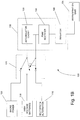
- Fig. 1A shows a block diagram of a construction of a system 100 for powering a refrigeration unit 105 using power from a belt driven alternator 110, from high-voltage batteries 115 of a hybrid vehicle, and from shore power 120.
- a switch 125 selects which of the three power sources 110, 115, and 120 is used.
- the switch 125 is a manual switch, where a user selects which power source 110, 115, and 120 to use.
- the switch 125 is automatic, where a controller senses which power source(s) are providing sufficient power to operate the refrigeration unit 105 and selects the most appropriate power source to use.
- shore power 120 is used whenever it is available, followed by power from the high-voltage batteries 115, and finally by power from the belt driven alternator 110.
- the controller may control operation of an internal combustion engine used to drive the alternator, turning on the engine when there is insufficient power available from the shore power 120 or the high-voltage batteries 115, and turning off the engine when there is sufficient power available from either the shore power 120 or the high-voltage batteries 115, thus saving energy (i.e., fuel).
- the power available from the belt driven alternator 110 is about 150 to 600 volts AC (VAC)
- the power available from the high-voltage batteries 115 is about 263 to 408 volts DC (VDC)
- the power available from shore power 120 is about 150 to 600 VAC.
- AC power is assumed to be three-phase, however the invention contemplates the use of single-phase AC power as well.
- the power from one of the power sources 110, 115, and 120 is applied a power converter 130 including an accumulation choke 135, a pulse-width-modulated (PWM) rectifier 140, and a frequency inverter 145.
- the accumulation choke 135 is coupled to the PWM rectifier 140.
- the accumulation choke 135 operates with the PWM rectifier 140 to convert/modify the power received from the belt driven alternator 110, the high-voltage batteries 115, or the share power 120 to a DC voltage having a maximum amplitude of about 750 VDC.
- the DC voltage is provided to the frequency inverter 145 which converts the DC voltage to a variable voltage of 0 to 525 VAC having a frequency of about 0 to 100 Hz, which is provided to the refrigeration unit 105.
- the DC power from the PWM rectifier 140 is also used to supply a DC chopper for an electric heater.
- the DC chopper provides DC power having a variable voltage of about 0 to 750 V DC.
- Fig. 1B shows a block diagram of an alternate construction of a system 100' for powering a refrigeration unit 105 using power from a belt driven alternator 110, from high-voltage batteries 115 of a hybrid vehicle, and from shore power 120.
- a switch 125' selects which of the three power sources 110, 115, and 120 is used.
- the switch 125' has multiple throws such that when power from the belt driven alternator 110 is selected, the alternator 110 is connected directly to the PWM rectifier 140, bypassing the accumulation choke 135.
- the operation of the system 100' is the same as the operation of system 100 described above.
- the construction shown in Fig. 1B can be used when the inductance of the belt driven alternator 110 is great enough that the accumulation choke 135 is not necessary.
- Fig. 2A shows a schematic diagram of a construction of the accumulation choke 135 and a full-controlled PWM rectifier 140'.
- the accumulation choke 135 includes a plurality of inductors 150.
- the full-controlled PWM rectifier 140' includes six insulated gate bipolar transistors (IGBT) 155-160, each IGBT 155-160 having a diode 165-170 connected across its collector and emitter, and a capacitor 175.
- IGBT insulated gate bipolar transistors
- Fig. 2B shows a schematic diagram of a construction of the accumulation choke 135 and a half-controlled PWM rectifier 140".
- the accumulation choke 135 includes a plurality of inductors 150.
- the half-controlled PWM rectifier 140" includes three insulated gate bipolar transistors (IGBT) 158-160, each IGBT 158-160 having a diode 168-170 connected across its collector and emitter, three diodes 155-157 connected in an upper branch of the half-controller PWM rectifier 140", and a capacitor 175.
- IGBT insulated gate bipolar transistors
- Fig. 3A shows a schematic representation of the accumulation choke 135 and a full-controlled PWM rectifier 140' for use with DC input power from the high-voltage batteries 115.
- the accumulation choke 135 and the full-controlled PWM rectifier 140' include all the same components as described above with respect to Fig. 2A ; however, the DC input voltage is applied to each inductor 150 and the upper IGBTs 155-157 are not used (i.e., they remain open).
- Fig. 3B shows a schematic diagram of a construction of the accumulation choke 135 and a half-controlled PWM rectifier 140" for use with DC input power from the high-voltage batteries 115.
- the accumulation choke 135 includes a plurality of inductors 150.
- the half-controlled PWM rectifier 140" includes three insulated gate bipolar transistors (IGBT) 158-160, each IGBT 158-160 having a diode 168-170 connected across its collector and emitter, three diodes 155-157 connected in an upper branch of the half-controller PWM rectifier 140", and a capacitor 175.
- IGBT insulated gate bipolar transistors
- Fig. 4 shows a block diagram of a construction of a hybrid vehicle system 200 including a refrigeration unit 205.
- the system 200 includes, among other things, a 12 VDC battery 210, a set of high-voltage batteries 215, a vehicle controller 220, a refrigeration unit controller 225, a refrigeration power system 230 including a connection to shore power 240, a refrigeration unit power switch 245, and a generator set including an internal combustion engine 250 driving an alternator 255.
- an internal combustion engine 250 drives a compressor and fans of the refrigeration unit 205 directly by one or more belts.
- an electric motor is powered by the shore power 240 and drives a compressor and fans of the refrigeration unit 205 directly by one or more belts.
- a master switch 260 enables the entire system 200.
- the power system 230 receives power from the shore power connection 240 and the high-voltage batteries 215, and provides power, if available, from either the shore power connection 240 or the high-voltage batteries 215 to the refrigeration unit power switch 245.
- the vehicle controller 220 provides an indication to the power system 230, via line 265, that power is available from the high-voltage batteries 215.
- the power system 230 provides to the refrigeration unit controller 225, via line 270, an indication that power is available from either the shore power connection 240 or the high-voltage batteries 215, and is being provided to the refrigeration unit power switch 245.
- the refrigeration unit controller 225 provides to the power unit 230, via line 275, an indication that the refrigeration unit 205 is on or off.
- the refrigeration unit controller 225 controls the refrigeration unit power switch 245, switching between power provided by the power system 230 or, if power is not available from the power system 230, power provided by the belt driven alternator 255.
- the refrigeration unit controller 225 turns on the internal combustion engine 250 which drives, via a belt, the alternator 255.
- the alternator 255 then provides power to the refrigeration unit power switch 245, which is set, by the refrigeration unit controller 225, to provide the power from the alternator 255 to the refrigeration unit 205.
- there may be no alternator present in the system 200 instead the internal combustion engine 250 drives a compressor and fans of the refrigeration unit 205 directly.
- Fig. 5 shows a construction of a portion of the power system 230.
- the system 230 includes an AC power connector 300 and a DC power connector 305.
- the AC connector 300 includes three connections L1, L2, and L3 for connecting three-phase shore power (if available) to the system 230.
- the DC connector 305 includes a positive 310 and a negative 315 connection for connecting to the high-voltage batteries 115.
- Each input line L1, L2, L3, 310, and 315 is connected to the rest of the system 230 through a fuse FSUP1-FSUP5 sized appropriately for the voltage and current received on its respective input line L1, L2, L3, 310, and 315.
- Each input line L1, L2, L3, 310, and 315 is also connected to the power converter 130 through a normally-open relay 320-326.
- the normally-open relays 320-322 are closed to provide the AC shore power to the power converter 130, and when shore power is not available and DC power from the high-voltage batteries 115 is available, the normally-open relays 323-326 are closed to provide the DC power to the power converter 130.
- the AC normally-open relays 320-322 are closed, the DC normally-open relays 323-326 are open, and when the DC normally-open relays 323-326 are closed, the AC normally-open relays 320-322 are open.
- an interlock module monitors relays 320-322 and 323-326 to ensure that only one of the relay groups 320-322 or 323-326 is closed at any time.
- the system 230 also includes AC pre-charging circuits having normally-open relays 330 and 331 and resistors 332 and 333, and a DC pre-charging circuit including a normally-open relay 334 and resistor 335.
- the pre-charging circuits are used when power is initially applied to the power system 230, and during a transition from AC power to DC power or from DC power to AC power. During a transition, the pre-charging circuits maintain power to the power converter 130, and allow the AC or DC power to be completely removed before the DC or AC power, being transitioned to, is connected.
- AC or DC power is provided to the accumulation choke 135 and the PWM rectifier 140 of the power converter 130.
- the accumulation choke 135 and the PWM rectifier 140 convert the AC or DC power to DC power having a maximum voltage of about 750 volts.
- the DC power is the provided to the inverter 145 which converts the DC power to three-phase AC power having a variable voltage of 0 to 525 volts and frequency of about 0 to 100 Hz. In the construction shown in Fig. 4 , this AC power is then provided to the refrigeration unit 205 via the refrigeration unit power switch 245.
- the DC power from the PWM rectifier 140 is also used to supply a DC chopper for an electric heater.
- the DC chopper provides DC power having a variable voltage of about 0 to 750 V DC.
- Fig. 6 shows a circuit 350 for controlling the application of AC or DC power to the power converter 130 for the system 230 shown in Fig. 5 .
- the circuit 350 includes an AC delay 355 having a normally-closed switch 360 and a normally-open switch 365, a DC delay 370 having a normally-closed switch 375 and a normally-open switch 380, and a plurality of coils 390-396 for closing corresponding normally-open relays 320-326 shown in Fig. 5 .
- a switch 400 selects either AC or DC power. In the construction shown, the switch 400 is a manual switch requiring an operator to select the AC or DC power.
- the switch 400 is an automatic switch where AC power is automatically chosen if available, and if AC power is not available but DC power is available, DC power is automatically chosen. In other embodiments, DC power is automatically chosen if available and AC power is chosen if available when DC power is not available. In some embodiments, if the switch 400 is off, and neither AC nor DC power is available, an internal combustion engine drives the refrigeration unit directly when the refrigeration unit is on.
- the switch 400 When the switch 400 is put into the AC position, power is provided to the AC delay 355 and to the AC pre-charge coil 395.
- the power provided to the AC pre-charge coil 395 closes the AC pre-charge normally-open relays 330-331 ( Fig. 5 ) applying AC power through resistors 332 and 333 to the power converter 130.
- the AC delay 355 opens the AC normally-closed switch 360 and closes the AC normally-open switch 365.
- the AC normally-closed switch 360 opens, power is removed from the AC pre-charge coil 395 and the AC pre-charge normally-open relays 330-331 open.
- the AC normally-open switch 365 closes, power is applied to the AC coil 396 and the AC normally-open relays 320-322 close providing three-phase AC power to the power converter 130.
- the switch 400 When the switch 400 is put into the DC position, power is provided to the DC delay 370 and to the DC pre-charge coil 391, and to DC negative coil 390.
- the power provided to the DC pre-charge coil 391 closes the DC pre-charge normally-open relay 334 ( Fig. 5 ) applying DC power through resistor 335 to the power converter 130.
- the power provided to the DC negative coil 390 closes the normally-open relay 326 connecting the negative connection 315 from the high-voltage batteries 215 to the power converter 130.
- a delay period e.g., five seconds
- the DC delay 370 opens the DC normally-closed switch 375 and closes the DC normally-open switch 380.
- Fig. 7 shows an alternative construction of a power converter 405 where multiple power converters 410-425 are employed for powering various devices such as a compressor motor 430, an electric heater 435, an evaporator fan 440, and a condenser fan 445.
- Figs. 8A and 8B show a schematic diagram of a construction of the power system 230 ( Fig. 4 ).
- system power is turned on (switch 260 in Fig. 4 is closed)
- normally-open relay K7 closes.
- shore power is available, i.e., three-phase AC power is provided to L1, L2, L3, and a phase select module 450 receives power from normally-open relay K7 and the AC power lines L1, L2, L3.
- the phase select module 450 then provides power to line 8EA.
- the power on line 8EA initiates a five second delay timer 455 and simultaneously powers coil P.
- the power to coil P closes normally-open relays P1 and P2, and opens normally-closed relay P2.
- the five second delay timer 455 provides power to output MPT which is provided to the refrigeration unit controller 225 to indicate that power is available from the power system 230 ( Fig. 4 ). If the refrigeration unit controller 225 indicates that the refrigeration unit 205 is on, normally-open relay K13 is closed providing power to coil MCA. The power to coil MCA causes normally-open relays MCA to close, supplying the AC shore power to the power converter 130, which in turn supplies power to a condenser motor 460 (providing normally-open relays K14 are closed).
- normally-closed relay P2 is closed. If AC shore power is not available, normally-closed relay P2 is closed. If the vehicle controller 220 ( Fig. 4 ) indicates that vehicle power is available, the vehicle controller 220 provides power to a five second delay timer 465. After a five second delay, the timer 465 allows power to be applied to a coil T closing normally-open relay T1 and providing power to output MPT, which is provided to the refrigeration unit controller 225 to indicate that power is available from the power system 230 ( Fig. 4 ). If the refrigeration unit controller 225 indicates that the refrigeration unit 205 is on, normally-open relay K13 is closed, providing power to coil MCB.
- the power to coil MCB causes normally-open relays MCB to close, supplying the DC power from the high-voltage batteries 215 to the power converter 130, which in turn supplies power to the condenser motor 460 (providing normally-open relays K14 are closed).
- the output MPT to the refrigeration unit controller 225 is low and the refrigeration unit controller 225 starts the engine 250 which drives the refrigeration unit 205 directly.
- Figs. 9A , 9B , 9C , and 9D show a schematic diagram of an alternative construction of a power system 500.
- Fig. 10 shows an alternate construction of a power system 505.
- the system 505 includes a first AC power connector 510, a second AC power connector 515, and a DC power connector 520.
- the first AC connector 510 includes three connections L1, L2, and L3 for connecting three-phase power from the belt driven alternator 255 to the system 505.
- the second AC connector 515 includes three connections L1', L2', and L3' for connecting three-phase shore power (if available) to the system 505.
- the DC connector 520 includes a positive connection 525 and a negative 530 connection for connecting to the high-voltage batteries 215 to the system 505.
- Each input line L1, L2, L3, L1', L2', L3', 525, and 530 is connected to the rest of the system 505 through a fuse FSUP1-FSUP8 sized appropriately for the voltage and current received on its respective input line L1, L2, L3, L1', L2', L3', 525, and 530.
- Each input line L1, L2, L3, L1', L2', L3', 525, and 530 is also connected to the power converter 130 through a normally-open relay 535-544.
- the normally-open relays 538-540 are closed to provide the AC shore power to the power converter 130
- the normally-open relays 541-544 are closed to provide the DC power to the power converter 130.
- the normally-open relays 535-537 are closed to provide AC power from the alternator 255 to the power converter 130. Only one set of normally-open relays 535-537, 538-540, or 541-544 are closed at any time.
- the system 505 also includes first AC pre-charging circuits having normally-open relays 550 and 551 and resistors 552 and 553, second AC pre-charging circuits having normally-open relays 555 and 556 and resistors 557 and 558, and a DC pre-charging circuit having a normally-open relay 560 and a resistor 561.
- the pre-charging circuits are used when power is initially applied to the power system 505, and during a transition between one input power to another to maintain power to the power converter 130 during the transition, and allowing the power being transitioned from to be completely removed before the power being transitioned to is connected.
- AC or DC power is provided to the accumulation choke 135 and the PWM rectifier 140 of the power converter 130 convert the AC or DC power to DC power having a maximum voltage of about 750 volts.
- the DC power is the provided to the inverter 145, which converts the DC power to three-phase AC power having a voltage of 0 to 525 volts. In the construction shown in Fig. 4 , this AC power is then provided to the refrigeration unit 205 via the refrigeration unit power switch 245.
- Fig. 11 shows a circuit 600 for controlling the application of the first AC power, the second AC power, or the DC power to the power converter 130 for the system 505 shown in Fig. 10 .
- the circuit 600 includes a first AC delay 605 having a normally-closed switch 610 and a normally-open switch 615, a second AC delay 620 having a normally-closed switch 625 and a normally-open switch 630, a DC delay 635 having a normally-closed switch 640 and a normally-open switch 645, and a plurality of coils 650-658 for closing corresponding normally-open relays 534-544, 550-551, 555, 556, and 560 shown in Fig. 10 .
- a switch 660 selects either the first AC power, the second AC power, or the DC power.
- the switch 660 is a manual switch requiring an operator to select the power.
- the switch 660 is an automatic switch where the second AC power (shore power) is automatically chosen if available, and if the first AC power is not available but DC power is available, the DC power is automatically chosen. If neither the second AC power nor the DC power is available, the switch automatically chooses the first AC power.
- the circuit 600 operates similar to the operation of circuit 350 of Fig. 6 with the addition of a second AC power.
- a liquid cooling system of the hybrid vehicle is used to cool one or more components of the power system 230 (e.g., the power converter 130) and/or one or more components of the alternator 255 (e.g., the belt driven alternator 110).
- a liquid cooling system of the refrigeration unit 205 is used to cool one or more components of the power system 230 and/or one or more components of the alternator 255.
- shore power is provided to a charging circuit, in addition to the power system 230, for charging the high-voltage batteries 215.
- the refrigeration unit 205 is operated exclusively using either DC power from the high-voltage batteries 215 or AC shore power 240.
- Fig. 12 shows a schematic diagram of an alternative construction of a full-controlled PWM rectifier 700 incorporating a pre-charging circuit 705.
- the full-controlled PWM rectifier 700 includes six insulated gate bipolar transistors (IGBT) 155-160, each IGBT 155-160 having a diode 165-170 connected across its collector and emitter, and operates the same as system 100 described above.
- the pre-charging circuit 705 includes a capacitor 715, a resistor 720, a diode 725, and an IGBT 730.
- the pre-charging circuit 705 operates to buffer a current surge encountered when switching from one power source to a second power source, and eliminates the need for the pre-charging and delay circuits described for the controllers above.
- the pre-charging circuit 705 operates by opening the IGBT 730 prior to transitioning the power source. Applying the second power source and removing the first power source while the IGBT 730 is open. The IGBT 730 is held open until the capacitor 715 is fully charged forcing current to travel through the resistor 720. Once the capacitor 715 is fully charged, the IGBT 730 is closed.
- Constructions of the invention are capable of being used in non-hybrid vehicles, receiving AC power from an alternator of the vehicle during operation of the vehicle and having a shore power connection for use when the vehicle is not operating.
- the invention provides, among other things, systems and method for powering a refrigeration unit of a hybrid vehicle.
- Figures 13 and 14 are original versions of Figures 8A , 8B and Figures 9A , 9B , 9C , 9D respectively, and the above description refers to Figures 8A , 8B and Figures 9A , 9B , 9C , 9D owing to their improved clarity.
Applications Claiming Priority (3)
| Application Number | Priority Date | Filing Date | Title |
|---|---|---|---|
| US15896409P | 2009-03-10 | 2009-03-10 | |
| PCT/US2010/026840 WO2010104960A1 (en) | 2009-03-10 | 2010-03-10 | Systems and methods of powering a refrigeration unit of a hybrid vehicle |
| EP10751362.4A EP2406560B1 (de) | 2009-03-10 | 2010-03-10 | Systeme und verfahren zum antreiben einer kühleinheit eines hybridfahrzeugs |
Related Parent Applications (1)
| Application Number | Title | Priority Date | Filing Date |
|---|---|---|---|
| EP10751362.4A Division EP2406560B1 (de) | 2009-03-10 | 2010-03-10 | Systeme und verfahren zum antreiben einer kühleinheit eines hybridfahrzeugs |
Publications (1)
| Publication Number | Publication Date |
|---|---|
| EP3734189A1 true EP3734189A1 (de) | 2020-11-04 |
Family
ID=42728750
Family Applications (2)
| Application Number | Title | Priority Date | Filing Date |
|---|---|---|---|
| EP20167375.3A Pending EP3734189A1 (de) | 2009-03-10 | 2010-03-10 | Systeme und verfahren zum antreiben einer kühleinheit eines hybridfahrzeugs |
| EP10751362.4A Active EP2406560B1 (de) | 2009-03-10 | 2010-03-10 | Systeme und verfahren zum antreiben einer kühleinheit eines hybridfahrzeugs |
Family Applications After (1)
| Application Number | Title | Priority Date | Filing Date |
|---|---|---|---|
| EP10751362.4A Active EP2406560B1 (de) | 2009-03-10 | 2010-03-10 | Systeme und verfahren zum antreiben einer kühleinheit eines hybridfahrzeugs |
Country Status (4)
| Country | Link |
|---|---|
| US (2) | US9689598B2 (de) |
| EP (2) | EP3734189A1 (de) |
| CN (1) | CN102422101B (de) |
| WO (1) | WO2010104960A1 (de) |
Families Citing this family (34)
| Publication number | Priority date | Publication date | Assignee | Title |
|---|---|---|---|---|
| DE102010003509A1 (de) * | 2010-03-31 | 2011-10-06 | Zf Friedrichshafen Ag | Energieversorgungsvorrichtung und Aggregat |
| US20120101673A1 (en) * | 2010-10-26 | 2012-04-26 | Jeffrey Andrew Caddick | Hybrid Vehicle Control System For Cold Plate Refrigeration And Method Of The Same |
| EP2694891B1 (de) * | 2011-04-04 | 2020-01-15 | Carrier Corporation | Transportkühlsystem und betriebsverfahren |
| JP5673474B2 (ja) * | 2011-09-27 | 2015-02-18 | 三菱自動車工業株式会社 | 電力切替装置 |
| US8605472B2 (en) * | 2011-10-12 | 2013-12-10 | Thermo King Corporation | Buck-boost rectifier, refrigeration system including a buck-boost rectifier, and method of providing power to a refrigeration unit via a buck-boost rectifier |
| US8953296B2 (en) * | 2011-11-14 | 2015-02-10 | Rockwell Automation Technologies, Inc. | AC pre-charge circuit |
| CN104684758B (zh) * | 2012-10-08 | 2018-03-23 | 冷王公司 | 用于为运输制冷系统提供动力的系统和方法 |
| EP2722964A3 (de) | 2012-10-22 | 2015-11-11 | Techtronic Outdoor Products Technology Limited | Doppelquellen-Batterieladegerät |
| WO2014106225A1 (en) * | 2012-12-31 | 2014-07-03 | Thermo King Corporation | Offset current implementation for battery charger |
| FR3002797B1 (fr) * | 2013-03-01 | 2015-04-03 | Arnauld Deloge | Installation de climatisation |
| US9960609B2 (en) | 2013-12-26 | 2018-05-01 | Thermo King Corporation | Method and system for configuring a transport refrigeration unit battery charger for use in a transport refrigeration system |
| KR102220911B1 (ko) * | 2014-01-06 | 2021-02-25 | 엘지전자 주식회사 | 냉장고, 및 홈 어플라이언스 |
| CN103944411A (zh) * | 2014-04-10 | 2014-07-23 | 重庆瑜欣平瑞电子有限公司 | 发电机变频器 |
| CN104038121B (zh) * | 2014-05-26 | 2016-08-17 | 株洲变流技术国家工程研究中心有限公司 | 永磁同步发电机整流系统 |
| US10300831B2 (en) | 2016-06-01 | 2019-05-28 | Cummins Inc. | Hybrid reefer systems |
| US10315495B2 (en) | 2016-06-30 | 2019-06-11 | Emerson Climate Technologies, Inc. | System and method of controlling compressor, evaporator fan, and condenser fan speeds during a battery mode of a refrigeration system for a container of a vehicle |
| US10300766B2 (en) | 2016-06-30 | 2019-05-28 | Emerson Climate Technologies, Inc. | System and method of controlling passage of refrigerant through eutectic plates and an evaporator of a refrigeration system for a container of a vehicle |
| US10828963B2 (en) | 2016-06-30 | 2020-11-10 | Emerson Climate Technologies, Inc. | System and method of mode-based compressor speed control for refrigerated vehicle compartment |
| US10328771B2 (en) | 2016-06-30 | 2019-06-25 | Emerson Climated Technologies, Inc. | System and method of controlling an oil return cycle for a refrigerated container of a vehicle |
| US10562377B2 (en) | 2016-06-30 | 2020-02-18 | Emerson Climate Technologies, Inc. | Battery life prediction and monitoring |
| US10569620B2 (en) | 2016-06-30 | 2020-02-25 | Emerson Climate Technologies, Inc. | Startup control systems and methods to reduce flooded startup conditions |
| US10532632B2 (en) | 2016-06-30 | 2020-01-14 | Emerson Climate Technologies, Inc. | Startup control systems and methods for high ambient conditions |
| US10414241B2 (en) | 2016-06-30 | 2019-09-17 | Emerson Climate Technologies, Inc. | Systems and methods for capacity modulation through eutectic plates |
| IT201700058521A1 (it) * | 2017-05-30 | 2018-11-30 | Denso Thermal Systems Spa | Unità condensante di un impianto frigorifero per veicoli adibiti al trasporto di merci deperibili. |
| US11554629B2 (en) | 2017-06-07 | 2023-01-17 | Carrier Corporation | Hybrid power conversion system for a refrigerated transport vehicle and method |
| CN107300670A (zh) * | 2017-06-08 | 2017-10-27 | 北京新能源汽车股份有限公司 | 车载充电机功率继电器的检测电路、车载充电机及汽车 |
| US10731907B2 (en) * | 2017-06-12 | 2020-08-04 | Lennox Industries, Inc. | Controlling systems with motor drives using pulse width modulation |
| SG11202002925TA (en) | 2017-10-05 | 2020-04-29 | Carrier Corp | Multi power converter unit for a trailer refrigeration unit |
| CN111148952A (zh) | 2017-10-06 | 2020-05-12 | 开利公司 | 具有能量存储设备的运输制冷系统 |
| EP3540340B1 (de) * | 2018-03-14 | 2023-06-28 | Carrier Corporation | Lastverwaltung für kühlwageneinheit |
| DE102020201902A1 (de) * | 2020-02-17 | 2021-08-19 | Zf Friedrichshafen Ag | Stromverteilereinheit für ein Nutzfahrzeug sowie Nutzfahrzeug mit dieser |
| EP3901542A1 (de) | 2020-04-22 | 2021-10-27 | Carrier Corporation | Spannungswandlungssystem für ein transportkühlsystem |
| EP3904141A1 (de) | 2020-04-29 | 2021-11-03 | Carrier Corporation | Kühlaggregat mit vorkühlung für batterieelektrische fahrzeuge |
| EP4281300A1 (de) * | 2021-01-26 | 2023-11-29 | Dometic Sweden AB | Fahrzeugklimaanlage |
Citations (4)
| Publication number | Priority date | Publication date | Assignee | Title |
|---|---|---|---|---|
| US4152661A (en) * | 1977-04-05 | 1979-05-01 | Licentia Patent-Verwaltungs-G.M.B.H. | Modulation amplifier |
| EP1504227A1 (de) * | 2002-04-29 | 2005-02-09 | Bergstrom, Inc. | Fahrzeugklima- und -heizanlage mit betrieb bei an- und abgestelltem motor |
| US20070241732A1 (en) * | 2006-04-12 | 2007-10-18 | Luyang Luo | Power management system with multiple power sources |
| WO2008094148A1 (en) * | 2007-01-31 | 2008-08-07 | Carrier Corporation | Integrated multiple power conversion system for transport refrigeration units |
Family Cites Families (43)
| Publication number | Priority date | Publication date | Assignee | Title |
|---|---|---|---|---|
| US4853553A (en) * | 1987-10-30 | 1989-08-01 | Hosie Alan P | Dual mode diesel electric power system for vehicles |
| JP2698657B2 (ja) * | 1989-05-19 | 1998-01-19 | サンデン株式会社 | 車両用冷凍装置 |
| US5432695A (en) * | 1993-09-17 | 1995-07-11 | The Center For Innovative Technology | Zero-voltage-switched, three-phase PWM rectifier inverter circuit |
| JP3260040B2 (ja) * | 1994-07-06 | 2002-02-25 | サンデン株式会社 | 電気自動車用空気調和装置の制御装置 |
| US6186254B1 (en) * | 1996-05-29 | 2001-02-13 | Xcelliss Fuel Cell Engines Inc. | Temperature regulating system for a fuel cell powered vehicle |
| US6013904A (en) * | 1997-10-29 | 2000-01-11 | Contour Hardenting, Inc. | Induction hardening apparatus for a crankshaft |
| US6123000A (en) * | 1998-09-04 | 2000-09-26 | Contour Hardeing, Inc. | Centering spindle for a machine tool including an isolation spacer |
| JP2000121202A (ja) * | 1998-10-12 | 2000-04-28 | Isuzu Motors Ltd | 冷凍・冷蔵車 |
| US6624533B1 (en) * | 1999-08-04 | 2003-09-23 | Westerbeke Corporation | Controlling generator power |
| US20030034147A1 (en) * | 2001-05-31 | 2003-02-20 | Houck Glenn M. | Apparatus which eliminates the need for idling by trucks |
| US6622505B2 (en) * | 2001-06-08 | 2003-09-23 | Thermo King Corporation | Alternator/invertor refrigeration unit |
| US6543240B2 (en) * | 2001-07-20 | 2003-04-08 | William W. Grafton | Combination airconditioning/heat system for emergency vehicle |
| US9694651B2 (en) * | 2002-04-29 | 2017-07-04 | Bergstrom, Inc. | Vehicle air conditioning and heating system providing engine on and off operation |
| US7253584B2 (en) * | 2002-09-12 | 2007-08-07 | General Motors Corporation | Isolated high voltage battery charger and integrated battery pack |
| US7614381B2 (en) * | 2003-03-28 | 2009-11-10 | Caterpillar Inc. | Power system with an integrated lubrication circuit |
| US20040189099A1 (en) * | 2003-03-28 | 2004-09-30 | Caterpillar Inc. | Shore power interface |
| US7151326B2 (en) * | 2003-09-23 | 2006-12-19 | Idle Free Systems, L.L.C. | System and method for safely and efficiently capturing power currently produced by already available power supplies to power electrical devices in a truck while its engine is turned off |
| KR100619010B1 (ko) * | 2003-12-09 | 2006-08-31 | 삼성전자주식회사 | 스텝 모터 제어 장치 및 방법 |
| US7057376B2 (en) * | 2004-01-14 | 2006-06-06 | Vanner, Inc. | Power management system for vehicles |
| US6979913B2 (en) * | 2004-02-20 | 2005-12-27 | Contour Hardening, Inc. | Vehicle mounted electrical generator system |
| US7287582B2 (en) * | 2004-05-19 | 2007-10-30 | Eaton Corporation | Shore power system including a HVAC system |
| US7145788B2 (en) * | 2004-07-27 | 2006-12-05 | Paccar Inc | Electrical power system for vehicles requiring electrical power while the vehicle engine is not in operation |
| US7408273B2 (en) * | 2004-10-12 | 2008-08-05 | Slocum Kim M | Shore power access system |
| JP2006123658A (ja) * | 2004-10-27 | 2006-05-18 | Mitsubishi Fuso Truck & Bus Corp | 車両の電子機器取付構造 |
| US7005829B2 (en) * | 2005-03-01 | 2006-02-28 | York International Corp. | System for precharging a DC link in a variable speed drive |
| US7692401B2 (en) * | 2005-03-22 | 2010-04-06 | Ford Motor Company | High voltage battery pack cycler for a vehicle |
| US7266962B2 (en) * | 2005-05-17 | 2007-09-11 | Whirlpool Corporation | Battery supplemented refrigerator and method for using same |
| US20070023210A1 (en) * | 2005-07-28 | 2007-02-01 | Caterpillar Inc. | Electrical system of a mobile machine |
| US7765824B2 (en) * | 2006-02-01 | 2010-08-03 | Paccar Inc | Vehicle interior cooling system |
| US20070209378A1 (en) * | 2006-03-10 | 2007-09-13 | Larson Gerald L | Vehicle integrated power and control strategy for cold plate refrigeration system |
| US20080011007A1 (en) * | 2006-03-10 | 2008-01-17 | International Truck Intellectual Property Company, Llc | Cold plate refrigeration system optimized for energy efficiency |
| US7241146B1 (en) * | 2006-03-15 | 2007-07-10 | Shurepower, Llc | Shore power wire harness |
| US20070221370A1 (en) * | 2006-03-21 | 2007-09-27 | Dometic Environmental Corporation | Power supply system for a vehicle climate control unit |
| US7377237B2 (en) * | 2006-09-13 | 2008-05-27 | Cummins Power Generation Inc. | Cooling system for hybrid power system |
| US7531977B2 (en) * | 2006-09-19 | 2009-05-12 | Ise Corporation | HVAC system and method for over the road motor coaches |
| US8085002B2 (en) * | 2006-12-29 | 2011-12-27 | Cummins Power Generation Ip, Inc. | Shore power transfer switch |
| US7855466B2 (en) * | 2006-12-29 | 2010-12-21 | Cummins Power Generation Ip, Inc. | Electric power generation system with current-controlled power boost |
| US20080271937A1 (en) * | 2007-05-01 | 2008-11-06 | Ford Global Technologies, Llc | System and method for powering a power consuming vehicle accessory during an off state of the vehicle |
| US7769505B2 (en) * | 2007-05-03 | 2010-08-03 | Gm Global Technology Operations, Inc. | Method of operating a plug-in hybrid electric vehicle |
| US8986191B2 (en) * | 2007-06-28 | 2015-03-24 | Zhengping Zhang | Disposable device for vaginal cleaning and hygiene |
| WO2009029205A1 (en) * | 2007-08-30 | 2009-03-05 | Dimplex Thermal Solutions | Refrigeration power system for a storage compartment in a vehicle |
| US7889524B2 (en) * | 2007-10-19 | 2011-02-15 | Illinois Institute Of Technology | Integrated bi-directional converter for plug-in hybrid electric vehicles |
| US20110162395A1 (en) * | 2008-09-17 | 2011-07-07 | Bruno Chakiachvili | Electrically powered transport refrigeration units |
-
2010
- 2010-03-10 CN CN201080020381.XA patent/CN102422101B/zh active Active
- 2010-03-10 WO PCT/US2010/026840 patent/WO2010104960A1/en active Application Filing
- 2010-03-10 EP EP20167375.3A patent/EP3734189A1/de active Pending
- 2010-03-10 US US12/721,325 patent/US9689598B2/en active Active
- 2010-03-10 EP EP10751362.4A patent/EP2406560B1/de active Active
-
2017
- 2017-06-19 US US15/626,317 patent/US10480840B2/en active Active
Patent Citations (4)
| Publication number | Priority date | Publication date | Assignee | Title |
|---|---|---|---|---|
| US4152661A (en) * | 1977-04-05 | 1979-05-01 | Licentia Patent-Verwaltungs-G.M.B.H. | Modulation amplifier |
| EP1504227A1 (de) * | 2002-04-29 | 2005-02-09 | Bergstrom, Inc. | Fahrzeugklima- und -heizanlage mit betrieb bei an- und abgestelltem motor |
| US20070241732A1 (en) * | 2006-04-12 | 2007-10-18 | Luyang Luo | Power management system with multiple power sources |
| WO2008094148A1 (en) * | 2007-01-31 | 2008-08-07 | Carrier Corporation | Integrated multiple power conversion system for transport refrigeration units |
Also Published As
| Publication number | Publication date |
|---|---|
| WO2010104960A1 (en) | 2010-09-16 |
| US10480840B2 (en) | 2019-11-19 |
| US9689598B2 (en) | 2017-06-27 |
| EP2406560A4 (de) | 2015-04-29 |
| EP2406560A1 (de) | 2012-01-18 |
| CN102422101B (zh) | 2014-02-26 |
| EP2406560B1 (de) | 2020-04-29 |
| US20100229581A1 (en) | 2010-09-16 |
| CN102422101A (zh) | 2012-04-18 |
| US20170292745A1 (en) | 2017-10-12 |
Similar Documents
| Publication | Publication Date | Title |
|---|---|---|
| US10480840B2 (en) | Systems and methods of powering a refrigeration unit of a hybrid vehicle | |
| US11192451B2 (en) | Methods and systems for energy management of a transport climate control system | |
| US11260723B2 (en) | Methods and systems for power and load management of a transport climate control system | |
| EP3647089B1 (de) | Verfahren und system zur steuerung eines milden hybridsystems, das ein transportklimasystem speist | |
| US10870333B2 (en) | Reconfigurable utility power input with passive voltage booster | |
| CN109476211B (zh) | 用于运输制冷单元的高压系统 | |
| US9610824B2 (en) | Power supply system for a vehicle climate control unit | |
| US8432126B2 (en) | Rapid offboard charging via selective energizing of designated semiconductor switches and induction coils in an electric or hybrid electric vehicle | |
| US5086266A (en) | Automobile ac generator system | |
| US20080034773A1 (en) | System and method for automatic control of catering truck refrigeration | |
| CA2886166C (en) | Power management and environmental control system for vehicles | |
| KR101716456B1 (ko) | 냉동 탑차용 전력공급 시스템 | |
| US20050167090A1 (en) | Load management auxiliary power system | |
| WO2009087552A2 (en) | Hybrid vehicle for transportation of a refrigerated commercial load | |
| CN109861362B (zh) | 一种机车无动力回送辅助供电及自走行装置 | |
| JP6699362B2 (ja) | 車両用電源装置 | |
| US20220297501A1 (en) | Transport climate control system with a self-configuring matrix power converter | |
| JP2005098623A (ja) | 冷凍車用電源装置 | |
| JP7311279B2 (ja) | 輸送用冷凍機械 | |
| JP2004225991A (ja) | 車載用冷凍装置 | |
| JP3703984B2 (ja) | 車両の冷凍冷蔵システム |
Legal Events
| Date | Code | Title | Description |
|---|---|---|---|
| PUAI | Public reference made under article 153(3) epc to a published international application that has entered the european phase |
Free format text: ORIGINAL CODE: 0009012 |
|
| STAA | Information on the status of an ep patent application or granted ep patent |
Free format text: STATUS: THE APPLICATION HAS BEEN PUBLISHED |
|
| AC | Divisional application: reference to earlier application |
Ref document number: 2406560 Country of ref document: EP Kind code of ref document: P |
|
| AK | Designated contracting states |
Kind code of ref document: A1 Designated state(s): AT BE BG CH CY CZ DE DK EE ES FI FR GB GR HR HU IE IS IT LI LT LU LV MC MK MT NL NO PL PT RO SE SI SK SM TR |
|
| STAA | Information on the status of an ep patent application or granted ep patent |
Free format text: STATUS: REQUEST FOR EXAMINATION WAS MADE |
|
| 17P | Request for examination filed |
Effective date: 20210504 |
|
| RBV | Designated contracting states (corrected) |
Designated state(s): AT BE BG CH CY CZ DE DK EE ES FI FR GB GR HR HU IE IS IT LI LT LU LV MC MK MT NL NO PL PT RO SE SI SK SM TR |
|
| STAA | Information on the status of an ep patent application or granted ep patent |
Free format text: STATUS: EXAMINATION IS IN PROGRESS |
|
| 17Q | First examination report despatched |
Effective date: 20230221 |
|
| RAP3 | Party data changed (applicant data changed or rights of an application transferred) |
Owner name: THERMO KING LLC |