EP3734082A1 - Hydrostatic linear driving system - Google Patents
Hydrostatic linear driving system Download PDFInfo
- Publication number
- EP3734082A1 EP3734082A1 EP20164176.8A EP20164176A EP3734082A1 EP 3734082 A1 EP3734082 A1 EP 3734082A1 EP 20164176 A EP20164176 A EP 20164176A EP 3734082 A1 EP3734082 A1 EP 3734082A1
- Authority
- EP
- European Patent Office
- Prior art keywords
- fluid
- connection
- cylinder
- hydraulic
- pressure
- Prior art date
- Legal status (The legal status is an assumption and is not a legal conclusion. Google has not performed a legal analysis and makes no representation as to the accuracy of the status listed.)
- Pending
Links
- 230000002706 hydrostatic effect Effects 0.000 title claims description 24
- 239000012530 fluid Substances 0.000 claims abstract description 181
- 230000001360 synchronised effect Effects 0.000 claims description 36
- 239000007788 liquid Substances 0.000 claims description 22
- 230000008878 coupling Effects 0.000 claims description 12
- 238000010168 coupling process Methods 0.000 claims description 12
- 238000005859 coupling reaction Methods 0.000 claims description 12
- 230000036316 preload Effects 0.000 claims description 12
- 238000006073 displacement reaction Methods 0.000 claims description 11
- 230000005540 biological transmission Effects 0.000 claims description 9
- 230000002441 reversible effect Effects 0.000 claims description 3
- 230000033001 locomotion Effects 0.000 abstract description 13
- 238000005265 energy consumption Methods 0.000 abstract description 3
- 238000000071 blow moulding Methods 0.000 abstract description 2
- 239000002655 kraft paper Substances 0.000 description 4
- 230000008859 change Effects 0.000 description 3
- 230000003993 interaction Effects 0.000 description 2
- 230000001133 acceleration Effects 0.000 description 1
- 230000000903 blocking effect Effects 0.000 description 1
- 238000010276 construction Methods 0.000 description 1
- 230000006837 decompression Effects 0.000 description 1
- 238000001746 injection moulding Methods 0.000 description 1
- 238000000034 method Methods 0.000 description 1
- 230000008569 process Effects 0.000 description 1
- 230000009467 reduction Effects 0.000 description 1
- 239000000243 solution Substances 0.000 description 1
Images


Classifications
-
- F—MECHANICAL ENGINEERING; LIGHTING; HEATING; WEAPONS; BLASTING
- F15—FLUID-PRESSURE ACTUATORS; HYDRAULICS OR PNEUMATICS IN GENERAL
- F15B—SYSTEMS ACTING BY MEANS OF FLUIDS IN GENERAL; FLUID-PRESSURE ACTUATORS, e.g. SERVOMOTORS; DETAILS OF FLUID-PRESSURE SYSTEMS, NOT OTHERWISE PROVIDED FOR
- F15B15/00—Fluid-actuated devices for displacing a member from one position to another; Gearing associated therewith
- F15B15/18—Combined units comprising both motor and pump
-
- F—MECHANICAL ENGINEERING; LIGHTING; HEATING; WEAPONS; BLASTING
- F15—FLUID-PRESSURE ACTUATORS; HYDRAULICS OR PNEUMATICS IN GENERAL
- F15B—SYSTEMS ACTING BY MEANS OF FLUIDS IN GENERAL; FLUID-PRESSURE ACTUATORS, e.g. SERVOMOTORS; DETAILS OF FLUID-PRESSURE SYSTEMS, NOT OTHERWISE PROVIDED FOR
- F15B11/00—Servomotor systems without provision for follow-up action; Circuits therefor
- F15B11/02—Systems essentially incorporating special features for controlling the speed or actuating force of an output member
- F15B11/028—Systems essentially incorporating special features for controlling the speed or actuating force of an output member for controlling the actuating force
- F15B11/036—Systems essentially incorporating special features for controlling the speed or actuating force of an output member for controlling the actuating force by means of servomotors having a plurality of working chambers
-
- F—MECHANICAL ENGINEERING; LIGHTING; HEATING; WEAPONS; BLASTING
- F15—FLUID-PRESSURE ACTUATORS; HYDRAULICS OR PNEUMATICS IN GENERAL
- F15B—SYSTEMS ACTING BY MEANS OF FLUIDS IN GENERAL; FLUID-PRESSURE ACTUATORS, e.g. SERVOMOTORS; DETAILS OF FLUID-PRESSURE SYSTEMS, NOT OTHERWISE PROVIDED FOR
- F15B11/00—Servomotor systems without provision for follow-up action; Circuits therefor
- F15B11/02—Systems essentially incorporating special features for controlling the speed or actuating force of an output member
- F15B11/04—Systems essentially incorporating special features for controlling the speed or actuating force of an output member for controlling the speed
-
- B—PERFORMING OPERATIONS; TRANSPORTING
- B29—WORKING OF PLASTICS; WORKING OF SUBSTANCES IN A PLASTIC STATE IN GENERAL
- B29C—SHAPING OR JOINING OF PLASTICS; SHAPING OF MATERIAL IN A PLASTIC STATE, NOT OTHERWISE PROVIDED FOR; AFTER-TREATMENT OF THE SHAPED PRODUCTS, e.g. REPAIRING
- B29C49/00—Blow-moulding, i.e. blowing a preform or parison to a desired shape within a mould; Apparatus therefor
- B29C49/42—Component parts, details or accessories; Auxiliary operations
- B29C49/56—Opening, closing or clamping means
-
- B—PERFORMING OPERATIONS; TRANSPORTING
- B30—PRESSES
- B30B—PRESSES IN GENERAL
- B30B15/00—Details of, or accessories for, presses; Auxiliary measures in connection with pressing
- B30B15/16—Control arrangements for fluid-driven presses
- B30B15/161—Control arrangements for fluid-driven presses controlling the ram speed and ram pressure, e.g. fast approach speed at low pressure, low pressing speed at high pressure
-
- F—MECHANICAL ENGINEERING; LIGHTING; HEATING; WEAPONS; BLASTING
- F15—FLUID-PRESSURE ACTUATORS; HYDRAULICS OR PNEUMATICS IN GENERAL
- F15B—SYSTEMS ACTING BY MEANS OF FLUIDS IN GENERAL; FLUID-PRESSURE ACTUATORS, e.g. SERVOMOTORS; DETAILS OF FLUID-PRESSURE SYSTEMS, NOT OTHERWISE PROVIDED FOR
- F15B1/00—Installations or systems with accumulators; Supply reservoir or sump assemblies
- F15B1/02—Installations or systems with accumulators
- F15B1/021—Installations or systems with accumulators used for damping
-
- F—MECHANICAL ENGINEERING; LIGHTING; HEATING; WEAPONS; BLASTING
- F15—FLUID-PRESSURE ACTUATORS; HYDRAULICS OR PNEUMATICS IN GENERAL
- F15B—SYSTEMS ACTING BY MEANS OF FLUIDS IN GENERAL; FLUID-PRESSURE ACTUATORS, e.g. SERVOMOTORS; DETAILS OF FLUID-PRESSURE SYSTEMS, NOT OTHERWISE PROVIDED FOR
- F15B1/00—Installations or systems with accumulators; Supply reservoir or sump assemblies
- F15B1/02—Installations or systems with accumulators
- F15B1/024—Installations or systems with accumulators used as a supplementary power source, e.g. to store energy in idle periods to balance pump load
-
- F—MECHANICAL ENGINEERING; LIGHTING; HEATING; WEAPONS; BLASTING
- F15—FLUID-PRESSURE ACTUATORS; HYDRAULICS OR PNEUMATICS IN GENERAL
- F15B—SYSTEMS ACTING BY MEANS OF FLUIDS IN GENERAL; FLUID-PRESSURE ACTUATORS, e.g. SERVOMOTORS; DETAILS OF FLUID-PRESSURE SYSTEMS, NOT OTHERWISE PROVIDED FOR
- F15B11/00—Servomotor systems without provision for follow-up action; Circuits therefor
- F15B11/02—Systems essentially incorporating special features for controlling the speed or actuating force of an output member
- F15B11/022—Systems essentially incorporating special features for controlling the speed or actuating force of an output member in which a rapid approach stroke is followed by a slower, high-force working stroke
-
- F—MECHANICAL ENGINEERING; LIGHTING; HEATING; WEAPONS; BLASTING
- F15—FLUID-PRESSURE ACTUATORS; HYDRAULICS OR PNEUMATICS IN GENERAL
- F15B—SYSTEMS ACTING BY MEANS OF FLUIDS IN GENERAL; FLUID-PRESSURE ACTUATORS, e.g. SERVOMOTORS; DETAILS OF FLUID-PRESSURE SYSTEMS, NOT OTHERWISE PROVIDED FOR
- F15B11/00—Servomotor systems without provision for follow-up action; Circuits therefor
- F15B11/16—Servomotor systems without provision for follow-up action; Circuits therefor with two or more servomotors
- F15B11/17—Servomotor systems without provision for follow-up action; Circuits therefor with two or more servomotors using two or more pumps
-
- F—MECHANICAL ENGINEERING; LIGHTING; HEATING; WEAPONS; BLASTING
- F15—FLUID-PRESSURE ACTUATORS; HYDRAULICS OR PNEUMATICS IN GENERAL
- F15B—SYSTEMS ACTING BY MEANS OF FLUIDS IN GENERAL; FLUID-PRESSURE ACTUATORS, e.g. SERVOMOTORS; DETAILS OF FLUID-PRESSURE SYSTEMS, NOT OTHERWISE PROVIDED FOR
- F15B11/00—Servomotor systems without provision for follow-up action; Circuits therefor
- F15B11/16—Servomotor systems without provision for follow-up action; Circuits therefor with two or more servomotors
- F15B11/22—Synchronisation of the movement of two or more servomotors
-
- F—MECHANICAL ENGINEERING; LIGHTING; HEATING; WEAPONS; BLASTING
- F15—FLUID-PRESSURE ACTUATORS; HYDRAULICS OR PNEUMATICS IN GENERAL
- F15B—SYSTEMS ACTING BY MEANS OF FLUIDS IN GENERAL; FLUID-PRESSURE ACTUATORS, e.g. SERVOMOTORS; DETAILS OF FLUID-PRESSURE SYSTEMS, NOT OTHERWISE PROVIDED FOR
- F15B13/00—Details of servomotor systems ; Valves for servomotor systems
- F15B13/02—Fluid distribution or supply devices characterised by their adaptation to the control of servomotors
- F15B13/06—Fluid distribution or supply devices characterised by their adaptation to the control of servomotors for use with two or more servomotors
-
- F—MECHANICAL ENGINEERING; LIGHTING; HEATING; WEAPONS; BLASTING
- F15—FLUID-PRESSURE ACTUATORS; HYDRAULICS OR PNEUMATICS IN GENERAL
- F15B—SYSTEMS ACTING BY MEANS OF FLUIDS IN GENERAL; FLUID-PRESSURE ACTUATORS, e.g. SERVOMOTORS; DETAILS OF FLUID-PRESSURE SYSTEMS, NOT OTHERWISE PROVIDED FOR
- F15B15/00—Fluid-actuated devices for displacing a member from one position to another; Gearing associated therewith
- F15B15/08—Characterised by the construction of the motor unit
- F15B15/14—Characterised by the construction of the motor unit of the straight-cylinder type
- F15B15/149—Fluid interconnections, e.g. fluid connectors, passages
-
- F—MECHANICAL ENGINEERING; LIGHTING; HEATING; WEAPONS; BLASTING
- F15—FLUID-PRESSURE ACTUATORS; HYDRAULICS OR PNEUMATICS IN GENERAL
- F15B—SYSTEMS ACTING BY MEANS OF FLUIDS IN GENERAL; FLUID-PRESSURE ACTUATORS, e.g. SERVOMOTORS; DETAILS OF FLUID-PRESSURE SYSTEMS, NOT OTHERWISE PROVIDED FOR
- F15B1/00—Installations or systems with accumulators; Supply reservoir or sump assemblies
- F15B1/26—Supply reservoir or sump assemblies
-
- F—MECHANICAL ENGINEERING; LIGHTING; HEATING; WEAPONS; BLASTING
- F15—FLUID-PRESSURE ACTUATORS; HYDRAULICS OR PNEUMATICS IN GENERAL
- F15B—SYSTEMS ACTING BY MEANS OF FLUIDS IN GENERAL; FLUID-PRESSURE ACTUATORS, e.g. SERVOMOTORS; DETAILS OF FLUID-PRESSURE SYSTEMS, NOT OTHERWISE PROVIDED FOR
- F15B2211/00—Circuits for servomotor systems
- F15B2211/20—Fluid pressure source, e.g. accumulator or variable axial piston pump
- F15B2211/205—Systems with pumps
- F15B2211/2053—Type of pump
- F15B2211/20546—Type of pump variable capacity
-
- F—MECHANICAL ENGINEERING; LIGHTING; HEATING; WEAPONS; BLASTING
- F15—FLUID-PRESSURE ACTUATORS; HYDRAULICS OR PNEUMATICS IN GENERAL
- F15B—SYSTEMS ACTING BY MEANS OF FLUIDS IN GENERAL; FLUID-PRESSURE ACTUATORS, e.g. SERVOMOTORS; DETAILS OF FLUID-PRESSURE SYSTEMS, NOT OTHERWISE PROVIDED FOR
- F15B2211/00—Circuits for servomotor systems
- F15B2211/20—Fluid pressure source, e.g. accumulator or variable axial piston pump
- F15B2211/205—Systems with pumps
- F15B2211/2053—Type of pump
- F15B2211/20561—Type of pump reversible
-
- F—MECHANICAL ENGINEERING; LIGHTING; HEATING; WEAPONS; BLASTING
- F15—FLUID-PRESSURE ACTUATORS; HYDRAULICS OR PNEUMATICS IN GENERAL
- F15B—SYSTEMS ACTING BY MEANS OF FLUIDS IN GENERAL; FLUID-PRESSURE ACTUATORS, e.g. SERVOMOTORS; DETAILS OF FLUID-PRESSURE SYSTEMS, NOT OTHERWISE PROVIDED FOR
- F15B2211/00—Circuits for servomotor systems
- F15B2211/20—Fluid pressure source, e.g. accumulator or variable axial piston pump
- F15B2211/205—Systems with pumps
- F15B2211/20576—Systems with pumps with multiple pumps
-
- F—MECHANICAL ENGINEERING; LIGHTING; HEATING; WEAPONS; BLASTING
- F15—FLUID-PRESSURE ACTUATORS; HYDRAULICS OR PNEUMATICS IN GENERAL
- F15B—SYSTEMS ACTING BY MEANS OF FLUIDS IN GENERAL; FLUID-PRESSURE ACTUATORS, e.g. SERVOMOTORS; DETAILS OF FLUID-PRESSURE SYSTEMS, NOT OTHERWISE PROVIDED FOR
- F15B2211/00—Circuits for servomotor systems
- F15B2211/20—Fluid pressure source, e.g. accumulator or variable axial piston pump
- F15B2211/21—Systems with pressure sources other than pumps, e.g. with a pyrotechnical charge
- F15B2211/212—Systems with pressure sources other than pumps, e.g. with a pyrotechnical charge the pressure sources being accumulators
-
- F—MECHANICAL ENGINEERING; LIGHTING; HEATING; WEAPONS; BLASTING
- F15—FLUID-PRESSURE ACTUATORS; HYDRAULICS OR PNEUMATICS IN GENERAL
- F15B—SYSTEMS ACTING BY MEANS OF FLUIDS IN GENERAL; FLUID-PRESSURE ACTUATORS, e.g. SERVOMOTORS; DETAILS OF FLUID-PRESSURE SYSTEMS, NOT OTHERWISE PROVIDED FOR
- F15B2211/00—Circuits for servomotor systems
- F15B2211/20—Fluid pressure source, e.g. accumulator or variable axial piston pump
- F15B2211/27—Directional control by means of the pressure source
-
- F—MECHANICAL ENGINEERING; LIGHTING; HEATING; WEAPONS; BLASTING
- F15—FLUID-PRESSURE ACTUATORS; HYDRAULICS OR PNEUMATICS IN GENERAL
- F15B—SYSTEMS ACTING BY MEANS OF FLUIDS IN GENERAL; FLUID-PRESSURE ACTUATORS, e.g. SERVOMOTORS; DETAILS OF FLUID-PRESSURE SYSTEMS, NOT OTHERWISE PROVIDED FOR
- F15B2211/00—Circuits for servomotor systems
- F15B2211/70—Output members, e.g. hydraulic motors or cylinders or control therefor
- F15B2211/705—Output members, e.g. hydraulic motors or cylinders or control therefor characterised by the type of output members or actuators
- F15B2211/7051—Linear output members
- F15B2211/7055—Linear output members having more than two chambers
-
- F—MECHANICAL ENGINEERING; LIGHTING; HEATING; WEAPONS; BLASTING
- F15—FLUID-PRESSURE ACTUATORS; HYDRAULICS OR PNEUMATICS IN GENERAL
- F15B—SYSTEMS ACTING BY MEANS OF FLUIDS IN GENERAL; FLUID-PRESSURE ACTUATORS, e.g. SERVOMOTORS; DETAILS OF FLUID-PRESSURE SYSTEMS, NOT OTHERWISE PROVIDED FOR
- F15B2211/00—Circuits for servomotor systems
- F15B2211/70—Output members, e.g. hydraulic motors or cylinders or control therefor
- F15B2211/775—Combined control, e.g. control of speed and force for providing a high speed approach stroke with low force followed by a low speed working stroke with high force, e.g. for a hydraulic press
-
- F—MECHANICAL ENGINEERING; LIGHTING; HEATING; WEAPONS; BLASTING
- F15—FLUID-PRESSURE ACTUATORS; HYDRAULICS OR PNEUMATICS IN GENERAL
- F15B—SYSTEMS ACTING BY MEANS OF FLUIDS IN GENERAL; FLUID-PRESSURE ACTUATORS, e.g. SERVOMOTORS; DETAILS OF FLUID-PRESSURE SYSTEMS, NOT OTHERWISE PROVIDED FOR
- F15B2211/00—Circuits for servomotor systems
- F15B2211/70—Output members, e.g. hydraulic motors or cylinders or control therefor
- F15B2211/78—Control of multiple output members
- F15B2211/782—Concurrent control, e.g. synchronisation of two or more actuators
Definitions
- the invention relates to a hydrostatic linear drive system, in particular for a closing unit of a blow molding system.
- Hydrostatic linear drive systems are also used, for example, in hydraulic presses, deep-drawing or injection molding machines. Such machines usually have several motion sequences.
- One of these movement sequences is a so-called force path, in which a high force is exerted at low speed on the workpiece to be machined or the component to be moved.
- Another of these movement sequences is what is known as rapid traverse, with which less force is exerted, but which enables faster movement.
- Such a linear drive system is for example from DE 10 2016 113 882 A1 known.
- the known linear drive system has a hydraulic pump that is reversible in flow direction and is driven by an electric motor.
- the hydraulic pump is used to provide a variable volume flow of hydraulic fluid in a closed hydraulic circuit which includes a first differential cylinder as the master cylinder.
- the annular piston area on the rod side of the differential cylinder is smaller than the piston area on the piston side.
- the closed hydraulic circuit is closed off from its surroundings and has an overpressure in relation to the surroundings during operation. This overpressure is generated in a manner known per se by means of a bias source.
- the drive system requires an expansion tank.
- the expansion tank is preferably designed as a second differential cylinder, the cylinder space of which is open to the environment on the piston side and the annular area of which corresponds to the difference between the piston area and the annular area of the main cylinder.
- the piston rods of the two differential cylinders are mechanically coupled.
- a 2/2-way valve is arranged in the connecting line between the annular space of the second cylinder, which works as a compensation tank, and the annular space of the master cylinder.
- Another 2/2-way valve is arranged in a further connecting line between the annular space of the second cylinder, which works as a compensation tank, and the piston space of the main cylinder.
- the 2/2-way valve between the two annular spaces of the two differential cylinders is opened, while the other 2/2-way valve is blocked.
- the 2/2-way valve between the two annular spaces of the differential cylinder is blocked while the other 2/2-way valve is open.
- the expansion tank designed as a differential cylinder has the consequence that the extension and retraction of the main cylinder in rapid traverse always takes place against the resistance of the second cylinder working as an expansion tank, which means that high traverse speeds in rapid traverse with high forces in the power gear cannot be achieved.
- two 2/2-way valves are absolutely necessary for the operation of the drive system in rapid or power gear.
- the JP 46 14 544 B2 discloses a hydrostatic linear drive system with a 3-surface cylinder, one hydraulically active surface being provided for a power gear and two hydraulically active surfaces for an overdrive gear.
- the 3-surface cylinder is extended and retracted in rapid traverse by means of the two hydraulically active surfaces for high-speed gear, which can optionally be acted upon via a closed hydraulic circuit including a hydraulic pump.
- the cylinder space assigned to the hydraulically active surface for the power transmission is filled with fluid via a pre-tensioned expansion tank when it is extended in rapid traverse.
- this cylinder chamber is in fluid-conducting connection with a pump connected to a tank on the suction side and the pre-stressed expansion tank.
- the pressure of the pre-tensioned expansion tank acts against the extension direction on one of the two hydraulically active surfaces for the overdrive.
- the DE 10 2010 051 140 A1 discloses a linear drive system for a drawing press with a press frame in which a ram carrying an upper tool and a drawing cushion with a drawing cushion plate are mounted on which a workpiece hold-down is supported.
- the die cushion plate is mechanically coupled to the ram via a strut.
- Overdrive cylinders are provided for accelerated actuation of the tool hold-down device for its hydraulically driven up and down movement.
- clamping cylinders designed as plungers are provided on the die cushion plate; they are used to move and apply force to the workpiece hold-down relative to the Die cushion plate. The pistons of the clamping cylinder and the overdrive cylinder are coupled.
- the overdrive cylinders pre-accelerate the hold-down devices and the pistons of the clamping cylinders in the direction of movement of the ram.
- the clamping cylinder chambers are connected to a pretensioned low-pressure accumulator by means of check valves.
- the invention is based on the object of creating a linear drive system which has a simpler and more compact structure with at the same time a higher retraction and extension speed in rapid traverse, higher forces in the power operation and reduced energy consumption.
- the solution to this problem is based on the idea of bringing about the retraction and extension movement in rapid traverse by means of separate hydraulically active surfaces, which are independent of a larger hydraulically active surface that is only acted upon by pressurized hydraulic fluid in the force movement.
- the mechanical and hydraulic resistances are reduced by the fact that the larger hydraulically effective surface does not work against a pressurized hydraulic fluid in rapid traverse, but rather the hydraulic fluid to be displaced from the cylinder chamber is fed to an expansion tank that is open to the environment, ie not preloaded, or is fed to the cylinder chamber hydraulic fluid to be supplied is drawn in from the expansion tank.
- the hydraulically effective surfaces work together, what contributes to high forces with a compact design of the drive system.
- the retraction and extension of the cylinders in rapid traverse is brought about exclusively by the synchronous cylinder integrated into the closed hydraulic circuit.
- the first hydraulically effective surface of the single-acting cylinder is prevented from being subjected to hydraulic fluid.
- the extension of the cylinders in the power transmission is primarily effected by the single-acting cylinder, the first hydraulically effective surface of which is acted upon by the hydraulic fluid in the extension direction.
- the single-acting cylinder is supported during extension by the synchronous cylinder, the second hydraulically active surface of which is also acted upon with hydraulic fluid in the extension direction.
- the mechanical coupling between the single-acting cylinder and the synchronous cylinder takes place in particular via a coupling element between the piston rods of the two cylinders.
- the single-acting cylinder is a plunger cylinder, also referred to as a plunger cylinder.
- the piston rod of the plunger cylinder also serves as a piston.
- Plunger cylinder have a better mechanical efficiency than conventional, single-acting cylinders.
- the embodiment according to independent claim 2 relates to a linear drive system with a cylinder - hereinafter also referred to as a 3-surface cylinder - which integrates the hydraulically active surfaces of the single-acting cylinder and the synchronous cylinder of the embodiment according to independent claim 1 in one component and thus contributes to a particularly compact design.
- the extension and retraction of the 3-surface cylinder in rapid traverse is effected, as in the embodiment according to claim 1, exclusively by applying hydraulic fluid to the second or third hydraulically active surface. In rapid traverse, loading of the larger first hydraulically effective area is prevented.
- the extension of the 3-surface cylinder in power transmission is primarily effected by applying hydraulic fluid to the larger, first hydraulically active surface. However, as in the embodiment according to claim 1, the extension is assisted by acting on the second hydraulically active surface in the extension direction.
- the low-pressure connection of the second hydraulic pump is fluid-conducting with the expansion tank and the high-pressure connection is fluid-conducting with the first fluid connection of the single-acting cylinder in the embodiment according to claim 1 or with the first Fluid connection of the 3-surface cylinder according to claim 2 connected.
- the second hydraulic pump can be designed to be weaker than the first hydraulic pump, since it basically only has to provide the additional volume of hydraulic fluid, while the pressure build-up takes place primarily via the first hydraulic pump.
- a second hydraulic pump with correspondingly larger dimensions in the embodiment according to claim 3 can also make a significant contribution to the pressure build-up in the power transmission.
- the second hydraulic pump in the embodiment according to claim 3 can compensate for leakage oil in the closed hydraulic circuit and preload the closed hydraulic circuit.
- the first and / or second hydraulic pump in an advantageous embodiment of the invention provides a variable volume flow of the hydraulic fluid.
- the displacement volume and / or the drive speed of the first and / or second hydraulic pump can be variable.
- the hydraulic pump is driven, for example, by an electric motor whose speed and direction of rotation can be changed in order to change the volume flow and the direction of flow. If the drive is via an electric motor with a constant speed, the displacement volume of the hydraulic pump can be variable in order to change the volume flow. In the case of a variable displacement pump, the displacement volume is continuously changed, for example, by adjusting a swash plate. When the swash plate is adjusted through the zero position, the direction of flow of the volume flow changes, so that the direction of flow is reversed and the high-pressure and low-pressure sides of the variable displacement pump change.
- a particularly energy-saving operation with optimized overall efficiency is preferably achieved with a combination of a variable speed of the electric motor and a variable displacement volume of the variable displacement pump.
- the pressure connections of the first and / or the second hydraulic pump are connected to a pressure accumulator.
- the connection to the connections is made via check valves, which prevent a backflow from the pressure connections in the direction of the accumulator.
- the check valves open when the pressure at the pressure connections is lower than that in the pressure vessel. The pressure accumulator can therefore improve the dynamics of the linear drive system and / or save energy.
- the pressure connections of the first hydraulic pump are connected to a pressure accumulator, this can also serve as a preload source for the closed hydraulic circuit.
- the preload is primarily generated by means of a hydraulic pump.
- the preload pressure in the closed hydraulic circuit is higher than the ambient pressure.
- Ambient pressure is the hydrostatic pressure of the air at the location where the linear drive system is set up.
- the mean air pressure in the atmosphere is approximately 1 bar according to the standard.
- the preload pressure is 5-50 bar, preferably between 10-25 bar.
- the shut-off devices provided in the hydraulic lines serve the purpose of blocking or releasing the volume flow of the hydraulic fluid.
- the shut-off devices are preferably shut-off valves, in particular 2/2-way valves.
- the 2/2-way valve has two connections and two switching positions. In the first, closed switch position, the flow through the 2/2-way valve is blocked; in the second, open switch position, the flow through the 2/2-way valve is released.
- a throttle is arranged in the fluid-conducting connection between the expansion tank and the first fluid connection on the single-acting cylinder or the 3-surface cylinder.
- the throttle increases the pressure of the hydraulic fluid flowing through the fluid-conducting connection reduced.
- the throttle can be designed as an integral part of the shut-off valve.
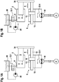
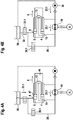
- Figure 1 shows a first embodiment of a hydrostatic linear drive system 1 with a single-acting cylinder 2, which is designed as a plunger cylinder.
- the plunger cylinder comprises a piston rod 3, a first hydraulically active surface 4 and a first cylinder chamber 5 with a first fluid connection 6 for a hydraulic fluid 7.
- the piston rod 3 is also the piston.
- the end face of the piston rod 3 facing the cylinder space 5 is the piston surface and is hydraulically effective.
- the first hydraulically active surface 4 of the single-acting cylinder 2 can be acted upon by the hydraulic fluid 7 in an extension direction 8 via the first fluid connection 6.
- the linear drive system 1 also has a synchronous cylinder 9, which has a piston rod 11, 12 on both sides of the piston 10.
- the annular piston surfaces that surround the piston rods 11, 12 form a second hydraulically active surface 13 and a third hydraulically active surface 14, which are the same in size.
- the synchronous cylinder 9 has a second liquid connection 15 and a third liquid connection 16, the second The fluid connection 15 opens into an annular second cylinder space 35 on the left side of the piston 10 and the third fluid connection 16 opens into a third annular cylinder space 36 on the right side of the piston 10.
- Hydraulic fluid 7 can be applied to second hydraulically active surface 13 in extension direction 8 via second fluid connection 15.
- the third hydraulically active surface 14 can be acted upon with hydraulic fluid 7 in the retraction direction 17 via the third fluid connection 16.
- a closed hydraulic circuit 18 under a preload pressure comprises the synchronous cylinder 9 and a first hydraulic pump 19 with a first and a second pressure connection 21, 22.
- An electric motor 20 drives the hydraulic pump 19 at constant or variable engine speed.
- the hydraulic pump 19 is preferably an axial piston variable displacement pump of the swashplate design. By adjusting the swash plate, the volume flow of the first hydraulic pump 19 can be changed continuously. When adjusting the swash plate through the zero position, the flow direction 23.1, 23.2 of the volume flow changes. The swivel angle is adjusted hydraulically via an actuating piston.
- the first pressure connection 21 is the high pressure side and the second pressure connection 22 is the low pressure side of the first hydraulic pump 19 or vice versa.
- the first pressure connection 21 is connected in a fluid-conducting manner to the second liquid connection 15 and the second pressure connection 22 is connected to the third liquid connection 16 via a hydraulic line 24, 25.
- the bias of the hydraulic fluid in the closed hydraulic circuit 18 can be generated, for example, by a pressure source (not shown) connected to the pressure connections 21, 22 (e.g. feed oil pump). Since the pretensioning of a closed hydraulic circuit 18 is known to the person skilled in the art, the components required for this have not been shown for the sake of clarity.
- a second hydraulic pump 26 with a low-pressure connection 27 and a high-pressure connection 28 is provided to apply hydraulic fluid 7 to the first hydraulically active surface 4 of the single-acting cylinder 2.
- the low-pressure connection 27 is fluid-conducting via a hydraulic line 29 with an expansion tank 30 and the high-pressure connection 28 is fluid-conducting via a hydraulic line 31 with the first liquid connection 6 of the single-acting cylinder 2.
- the expansion tank 30, which is open to the environment, receives hydraulic fluid 7 and is also connected in a fluid-conducting manner via a hydraulic line 32 to the first fluid connection 6 of the single-acting cylinder 2.
- a 2/2-way valve 33.1 is arranged as the first shut-off element 33 in the hydraulic line 32 between the expansion tank 30 and the single-acting cylinder 2.
- piston rod 3 of the single-acting cylinder 2 and the piston rod 12 of the synchronous cylinder 9 are mechanically connected to one another by means of a coupling member 34 such that the two cylinders move exclusively synchronously.
- Hydraulic fluid 7 is applied to the first hydraulically active surface 4 of the single-acting cylinder 2 via the first fluid connection 6 by means of the activated second hydraulic pump 26, whereby the single-acting cylinder 2 moves in the extension direction 8.
- the first hydraulic pump 19 is also activated in the flow direction 23.1, so that hydraulic fluid 7 is applied to the second hydraulically active surface 13 of the synchronous cylinder 9 via the second fluid connection 15.
- the synchronous cylinder moves synchronously with the single-acting cylinder 2, to which it is coupled via the coupling member 34, in the extension direction 8.
- a flow of the hydraulic fluid 7 via the hydraulic line 32 into the expansion tank 30 is prevented by the closed 2/2-way valve 33.1.
- the force generated during extension in the power transmission is generated by the interaction of the single-acting cylinder 2 and the synchronous cylinder 9 acted upon in the extension direction 8.
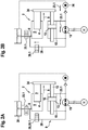
- Figure 2 shows a second embodiment of a hydrostatic linear drive system 1 with a single-acting cylinder 2, which is designed as a plunger cylinder.
- the plunger cylinder comprises a piston rod 3, a first hydraulically active surface 4 and a first cylinder chamber 5 with a first fluid connection 6 for a hydraulic fluid 7.
- the piston rod 3 is also the piston.
- the end face of the piston rod 3 facing the cylinder space 5 is the piston surface and is hydraulically effective.
- the first hydraulically active surface 4 of the single-acting cylinder 2 can be acted upon by the hydraulic fluid 7 in an extension direction 8 via the first fluid connection 6.
- the linear drive system 1 also has a synchronous cylinder 9, which has a piston rod 11, 12 on both sides of the piston 10.
- the annular piston surfaces that surround the piston rods 11, 12 form a second hydraulically active surface 13 and a third hydraulically active surface 14, which are the same in size.
- the synchronous cylinder 9 has a second liquid connection 15 and a third liquid connection 16, the second liquid connection 15 in an annular second Cylinder space 35 on the left side of the piston 10 and the third fluid connection 16 opens into a third annular cylinder space 36 on the right side of the piston 10.
- Hydraulic fluid 7 can be applied to second hydraulically active surface 13 in extension direction 8 via second fluid connection 15.
- the third hydraulically active surface 14 can be acted upon with hydraulic fluid 7 in the retraction direction 17 via the third fluid connection 16.
- a closed hydraulic circuit 18 under a preload pressure comprises the synchronous cylinder 9 and a first hydraulic pump 19 with a first and a second pressure connection 21, 22.
- An electric motor 20 drives the hydraulic pump 19 at constant or variable engine speed.
- the hydraulic pump 19 is preferably an axial piston variable displacement pump in the swashplate design as in the embodiment according to FIG Figure 1 .
- the first pressure connection 21 is connected in a fluid-conducting manner to the second liquid connection 15 and the second pressure connection 22 is connected to the third liquid connection 16 via a hydraulic line 24, 25.
- the bias of the hydraulic fluid in the closed hydraulic circuit 18 can be generated, for example, by a pressure source (not shown) connected to the pressure connections 21, 22.
- the first fluid connection 6 of the single-acting cylinder 2 is connected to the first pressure connection 21 of the first hydraulic pump 19 in a fluid-conducting manner via a hydraulic line 38.
- a second shut-off element 39 is arranged, which is designed as a 2/2-way valve 39.1.
- a high-pressure connection 28 of a second hydraulic pump 26 is connected in a fluid-conducting manner to the second pressure connection 22 of the first hydraulic pump 19 via a hydraulic line 31.
- a check valve 40 in the hydraulic line 31 prevents the hydraulic fluid 7 from flowing back in the direction of the second hydraulic pump 26.
- a low-pressure connection 27 of the second hydraulic pump 26 is connected in a fluid-conducting manner to the expansion tank 30 via a hydraulic line 29.
- the high-pressure connection 28 of the second hydraulic pump 26 is not directly connected to the first fluid connection 6 of the single-acting cylinder 2 in a fluid-conducting manner, but indirectly via the flow path released by the open 2/2-way valve 39.1 and the first hydraulic pump 19 activated in the flow direction 23.1.
- the expansion tank 30, which is open to the environment, receives hydraulic fluid 7 and is also connected in a fluid-conducting manner via a hydraulic line 32 to the first fluid connection 6 of the single-acting cylinder 2.
- a 2/2-way valve 33.1 is arranged as the first shut-off element 33 in the hydraulic line 32 between the expansion tank 30 and the single-acting cylinder 2.
- piston rod 3 of the single-acting cylinder 2 and the piston rod 12 of the synchronous cylinder 9 are mechanically connected to one another by means of a coupling member 34 such that the two cylinders move exclusively synchronously.
- hydraulic fluid 7 When extending the linear drive system 1 in rapid traverse Figure 2A hydraulic fluid 7 is applied to the second hydraulically active surface 13 via the second fluid connection 15 by means of the first hydraulic pump 19 operating in the flow direction 23.1, whereby the piston 10 of the synchronous cylinder 9 moves in the extension direction 8.
- the piston rod 3 of the single-acting cylinder 2 which is connected to the piston rod 12 of the synchronous cylinder 9 via the coupling member 34, is also moved in the extension direction 8 without hydraulic fluid 7 being applied to its hydraulically active surface 4.
- the hydraulic fluid 7 passes through the opened 2/2-way valve 33.1 from the expansion tank 30 via the first fluid connection 6 into the cylinder space 5 of the single-acting cylinder 2 (suction).
- the first hydraulically active surface 4 of the single-acting cylinder 2 is not acted upon because the 2/2-way valve 39.1 in the hydraulic line 38 is closed.
- Hydraulic fluid 7 is applied to the third hydraulically active surface 14 via the third fluid connection 16 by means of the first hydraulic pump 19, which now works in the opposite flow direction 23.2, whereby the piston 10 of the synchronous cylinder 9 moves in the retraction direction 17.
- the via the coupling member 34 with The piston rod 3 of the single-acting cylinder 2 connected to the piston rod 12 of the synchronous cylinder 9 is also moved in the retraction direction 17 without hydraulic fluid 7 acting on its hydraulically active surface 4.
- the hydraulic fluid 7 is displaced from the cylinder space 5 of the single-acting cylinder 2 into the expansion tank 30 through the open 2/2-way valve 33.1.
- the 2/2-way valve 39.1 in the hydraulic line 38 is closed.
- hydraulic fluid 7 When extending the linear drive system 1 in the power gear Figure 2B hydraulic fluid 7 is applied to the first hydraulically active surface 4 of the single-acting cylinder 2 via the first fluid connection 6, as a result of which the single-acting cylinder 2 moves in the extension direction 8.
- the 2/2-way valve 39.1 in the hydraulic line 38 is now open.
- Both the first hydraulic pump 19 and the second hydraulic pump 26 are activated and deliver the hydraulic fluid 7 in the same flow direction 23.1 in the direction of the first fluid connection 6 of the single-acting cylinder 2.
- the activated second hydraulic pump 26 provides the required additional volume of hydraulic fluid 7 from the expansion tank 30 ready to apply hydraulic fluid 7 to the first hydraulically active surface 4 of the single-acting cylinder 2 via the first fluid connection 6 and also to the second hydraulically active surface 13 of the synchronous cylinder 9 via the second fluid connection 15.
- the synchronous cylinder 9 moves synchronously with the single-acting cylinder 2, with which it is coupled via the coupling member 34, in the extension direction 8.
- a flow of the Hydraulic fluid 7 through the hydraulic line 32 into the expansion tank 30 is prevented by the closed 2/2-way valve 33.1.
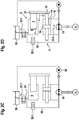
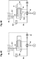
- FIG 3 shows a third embodiment of a hydrostatic linear drive system 1 with a 3-surface cylinder 42, which according to the functions of the single-acting cylinder 2 and the synchronous cylinder 9 of the embodiments Figures 1 and 2 integrated in an assembly.
- Matching components of the 3-surface cylinder 42 are provided with matching reference numerals.
- the 3-surface cylinder 42 has a cylinder tube 43, a cylinder base 44 closing off the cylinder tube 43 on one end face, and a piston rod guide 45 arranged on the opposite end face.
- the piston rod guide 45 guides a piston rod 46 in the axial direction.
- An annular piston 47 is arranged at one end of the piston rod 46.
- a guide pin 48 extends from the cylinder base 44 into the cylinder tube 43.
- the annular piston 47 surrounds the guide pin 48 and is slidable along the Guide pin 48 is guided in an extension direction 8 and a retraction direction 17.
- the piston rod 46 has a cavity 49 in the form of a blind hole which, starting from the central passage in the annular piston 47, extends into the piston rod 46 and surrounds the guide pin 48.
- the 3-surface cylinder has three hydraulically effective surfaces 4, 13, 14.
- the first hydraulically active surface 4 is formed by the first annular piston surface 47.1 facing the cylinder base 44 and delimits a first annular cylinder space 5.
- the second hydraulically active surface 13 is formed by a partial surface 50 of the cavity 49 which lies opposite the end face of the guide pin 48.
- the third hydraulically active surface 14 is formed by the second annular piston surface 47.2 facing the piston rod guide 45.
- a second ring-shaped cylinder space 51 is formed by the ring-shaped piston surface 47.2, the jacket of the piston rod 46, the inner surface of the cylinder tube 43 and, at the end, by the piston rod guide 45.
- the second and third hydraulically active surfaces 13, 14 are the same in size.
- the first cylinder chamber 5 has a first fluid connection 6, via which the first hydraulic connection effective surface 4 in the extension direction 8 of the 3-surface cylinder 42 can be acted upon with a hydraulic fluid 7.
- the second hydraulically active surface 13 can be acted upon by the hydraulic fluid 7 via a second fluid connection 15 in the extension direction 8.
- the second fluid connection 15 is located on the cylinder base 44. From there, the hydraulic fluid 7 passes via a fluid channel 52 to an outlet opening arranged on the end face of the guide pin 48.
- the third hydraulically active surface 14 can be acted upon by the hydraulic fluid 7 in a retraction direction 17 via the third fluid connection 16.
- the third liquid connection 16 opens into the second annular cylinder space 51.
- the first hydraulically active surface 4 can be acted upon by the hydraulic fluid 7 in the extension direction 8 via the first fluid connection 6.
- Hydraulic fluid 7 can be applied to second hydraulically active surface 13 in extension direction 8 via second fluid connection 15.
- the third hydraulically active surface 14 can be acted upon with hydraulic fluid 7 in the retraction direction 17 via the third fluid connection 16.
- a closed hydraulic circuit 18 under a preload pressure comprises the first hydraulic pump 19, the first pressure connection 21 being connected in a fluid-conducting manner to the second liquid connection 15 via the hydraulic line 24 and the second pressure connection 22 via the hydraulic line 25 to the third liquid connection 16.
- An electric motor 20 drives the first hydraulic pump 19 at constant or variable engine speed.
- the hydraulic pump 19 is preferably an axial piston variable displacement pump of the swashplate design. By adjusting the swash plate, the volume flow of the first hydraulic pump can be continuously changed and reversed.
- the prestressing of the hydraulic fluid in the closed hydraulic circuit 18 can be generated, for example, by a pressure vessel (not shown) connected to the pressure connections 21, 22 or by an external hydraulic pump.
- a second hydraulic pump 26 with a low-pressure connection 27 and a high-pressure connection 28 is provided in order to apply hydraulic fluid 7 to the first hydraulically active surface 4 of the 3-surface cylinder 42.
- the low-pressure connection 27 is fluid-conducting via a hydraulic line 29 with an expansion tank 30 and the high-pressure connection 28 is fluid-conducting via a hydraulic line 31 with the first liquid connection 6.
- the compensating tank 30, which is open to the environment, receives hydraulic fluid 7 and is also fluid-conducting via a hydraulic line 32 with the first fluid connection 6 of the 3-surface cylinder 42 connected.
- a 2/2-way valve 33.1 is arranged as the first shut-off element 33 in the hydraulic line 32 between the expansion tank 30 and the first fluid connection 6.
- hydraulic fluid 7 When extending the linear drive system 1 in rapid traverse Figure 3A hydraulic fluid 7 is applied to the second hydraulically active surface 13 via the second fluid connection 15 by means of the first hydraulic pump 19 operating in the flow direction 23.1, whereby the annular piston 47 moves with the piston rod 46 in the extension direction 8.
- the hydraulically active surface 4 is not acted upon by hydraulic fluid 7 in rapid traverse.
- the hydraulic fluid 7 passes through the opened 2/2-way valve 33.1 from the expansion tank 30 via the first fluid connection 6 into the first cylinder space 5 of the 3-surface cylinder 42 (suction).
- the second hydraulic pump 26, which is also connected to the first fluid connection 6, is not active.
- Hydraulic fluid 7 is applied to the third hydraulically active surface 14 via the third fluid connection 16 by means of the first hydraulic pump 19 now operating in the opposite flow direction 23.2, whereby the annular piston 47 moves with the piston rod 46 in the retraction direction 17.
- the hydraulically active surface 4 is not acted upon by hydraulic fluid 7.
- the hydraulic fluid 7 is displaced from the cylinder space 5 of the first cylinder space 5 into the expansion tank 30 through the open 2/2-way valve 33.1.
- the second hydraulic pump 26 connected to the first fluid connection 6 is not active.
- Hydraulic fluid 7 is applied to the first hydraulically active surface 4 of the 3-surface cylinder 42 via the first fluid connection 6 by means of the activated second hydraulic pump 26, whereby the 3-surface cylinder 42 moves in the extension direction 8.
- the first hydraulic pump 19 is also activated in the direction of flow 23.1, so that hydraulic fluid 7 is applied to the second hydraulically active surface 13 via the second fluid connection 15.
- a flow of the hydraulic fluid 7 from the first cylinder space 5 via the hydraulic line 32 into the expansion tank 30 is prevented by the closed 2/2-way valve 33.1.
- the force generated when extending in the power gear is generated by the interaction of the larger, first hydraulically active surface 4 and the smaller, second hydraulically active surface 13.
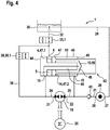
- FIG. 4 shows a fourth embodiment of a hydrostatic linear drive system 1 with a 3-surface cylinder 42, which the functions of the single-acting cylinder 2 and the synchronous cylinder 9 of FIG Embodiments according to Figures 1 and 2 integrated in an assembly.
- the 3-surface cylinder 42 is constructed in accordance with the 3-surface cylinder 42 of the third exemplary embodiment, so that in order to avoid repetition, refer to the explanations of FIG Figure 3 is referred. Differences arise with regard to the hydraulic supply of the 3-surface cylinder 42, which are explained in more detail below. The differences correspond to the differences between the second exemplary embodiment and the first exemplary embodiment.
- the first fluid connection 6 of the 3-surface cylinder 42 is connected in a fluid-conducting manner to the first pressure connection 21 of the first hydraulic pump 19 via a hydraulic line 38.
- a second shut-off element 39 is arranged, which is designed as a 2/2-way valve 39.1.
- a high-pressure connection 28 of a second hydraulic pump 26 is connected in a fluid-conducting manner to the second pressure connection 22 of the first hydraulic pump 19 via a hydraulic line 31.
- a check valve 40 in the hydraulic line 31 prevents the hydraulic fluid 7 from flowing back in the direction of the second hydraulic pump 26.
- the low-pressure connection 27 of the second hydraulic pump 26 is connected to the expansion tank 30 in a fluid-conducting manner via the hydraulic line 29.
- the high-pressure connection 28 of the second hydraulic pump 26 is not directly connected to the first liquid connection 6 of the 3-surface cylinder 42 in a fluid-conducting manner, but rather indirectly via the by the open 2/2-way valve 39.1 and the first hydraulic pump 19 activated in the flow direction 23.1, the flow path is released.
- the expansion tank 30, which is open to the environment, receives hydraulic fluid 7 and is connected in a fluid-conducting manner via a hydraulic line 32 to the first fluid connection 6 of the 3-surface cylinder 42.
- a 2/2-way valve 33.1 is arranged in the hydraulic line 32.
- hydraulic fluid 7 is applied to the second hydraulically active surface 13 via the second fluid connection 15 by means of the first hydraulic pump 19 operating in the flow direction 23.1, whereby the annular piston 47 moves with the piston rod 46 in the extension direction 8.
- the hydraulic fluid 7 passes through the opened 2/2-way valve 33.1 from the expansion tank 30 via the first fluid connection 6 into the cylinder space 5 of the 3-surface cylinder 42 (suction).
- the first hydraulically active surface 4 is not acted upon because the 2/2-way valve 39.1 in the hydraulic line 38 is closed.
- hydraulic fluid 7 When extending the linear drive system 1 in the power gear Figure 4B hydraulic fluid 7 is applied to the first hydraulically active surface 4 via the first fluid connection 6, as a result of which the 3-surface cylinder 42 moves in the extension direction 8.
- the 2/2-way valve 39.1 in the hydraulic line 38 is now open.
- Both the first hydraulic pump 19 and the second hydraulic pump 26 are activated and deliver the hydraulic fluid 7 in the same flow direction 23.1 in the direction of the first fluid connection 6.
- the activated second hydraulic pump 26 provides the required additional volume of hydraulic fluid 7 from the expansion tank 30 in order to transfer over to apply hydraulic fluid 7 to the first fluid connection 6, the first hydraulically active surface 4 of the 3-surface cylinder 42 and, via the second fluid connection 15, also to the second hydraulically active surface 13.
- a flow of the hydraulic fluid 7 via the hydraulic line 32 into the expansion tank 30 is prevented by the closed 2/2-way valve 33.1.
Abstract
Um ein Linear-Antriebssystem zu schaffen, insbesondere für eine Schließeinhait einer Blasformanlage, die einen einfacheren und kompakteren Aufbau bei zugleich höherer Ein- und Ausfahrgeschwindigkeit im Eilgang, höheren Kräften im Kraftgang sowie reduziertem Energieverbrauch aufweist, wird eine Zylinderanordnung vorgeschlagen, die eine Ein- und Ausfahrbewegung im Eilgang mittels gesonderter hydraulisch wirksamer Flächen bewirkt, die unabhängig von einer größeren hydraulisch wirksamen Fläche sind, die nur im Kraftgang mit unter Druck stehender Hydraulikflüssigkeit beaufschlagt wird. Während der Ausfahrbewegung im Kraftgang wirken die hydraulisch wirksamen Flächen jedoch zusammen, was zu hohen Kräften bei einem kompakten Aufbau des Antriebssystems beiträgt.In order to create a linear drive system, in particular for a closing unit of a blow molding system, which has a simpler and more compact structure with a higher retraction and extension speed in rapid traverse, higher forces in the power movement and reduced energy consumption, a cylinder arrangement is proposed which has an inlet and outlet The extension movement is effected in rapid traverse by means of separate hydraulically active surfaces, which are independent of a larger hydraulically active surface that is only acted upon by pressurized hydraulic fluid in the power movement. During the extension movement in the power gear, however, the hydraulically effective surfaces work together, which contributes to high forces with a compact design of the drive system.
Description
Die Erfindung betrifft ein hydrostatisches Linear-Antriebssystem, insbesondere für eine Schließeinheit einer Blasformanlage.The invention relates to a hydrostatic linear drive system, in particular for a closing unit of a blow molding system.
Hydrostatische Linear-Antriebssysteme kommen darüber hinaus beispielsweise in Hydraulikpressen, Tiefzieh-oder Spritzgießmaschinen zum Einsatz. Derartige Maschinen weisen in der Regel mehrere Bewegungsabläufe auf. Einer dieser Bewegungsabläufe ist ein sogenannter Kraftgang, bei dem auf das zu bearbeitende Werkstück bzw. das zu bewegende Bauteil eine hohe Kraft bei niedriger Geschwindigkeit ausgeübt wird. Ein weiterer dieser Bewegungsabläufe ist ein sogenannter Eilgang, mit dem eine geringere Kraft ausgeübt wird, der aber eine schnellere Bewegung ermöglicht.Hydrostatic linear drive systems are also used, for example, in hydraulic presses, deep-drawing or injection molding machines. Such machines usually have several motion sequences. One of these movement sequences is a so-called force path, in which a high force is exerted at low speed on the workpiece to be machined or the component to be moved. Another of these movement sequences is what is known as rapid traverse, with which less force is exerted, but which enables faster movement.
Ein derartiges Linear-Antriebssystem ist beispielsweise aus der
Der als Differentialzylinder ausgeführte Ausgleichsbehälter hat zur Folge, dass die Aus-und Einfahrbewegung des Hauptzylinders im Eilgang stets gegen den Widerstand des als Ausgleichsbehälter arbeitenden zweiten Zylinders erfolgt, wodurch hohe Verfahrgeschwindigkeiten im Eilgang bei zugleich großen Kräften im Kraftgang nicht realisiert werden können. Für den Betrieb des Antriebssystems im Eil-oder Kraftgang sind zudem zwingend zwei 2/2-Wegeventile erforderlich.The expansion tank designed as a differential cylinder has the consequence that the extension and retraction of the main cylinder in rapid traverse always takes place against the resistance of the second cylinder working as an expansion tank, which means that high traverse speeds in rapid traverse with high forces in the power gear cannot be achieved. In addition, two 2/2-way valves are absolutely necessary for the operation of the drive system in rapid or power gear.
Die
Die
Ausgehend von diesem Stand der Technik liegt der Erfindung die Aufgabe zugrunde, ein Linear-Antriebssystem zu schaffen, das einen einfacheren und kompakteren Aufbau bei zugleich höherer Ein-und Ausfahrgeschwindigkeit im Eilgang, höheren Kräften im Kraftgang sowie reduziertem Energieverbrauch aufweist.The
On the basis of this prior art, the invention is based on the object of creating a linear drive system which has a simpler and more compact structure with at the same time a higher retraction and extension speed in rapid traverse, higher forces in the power operation and reduced energy consumption.
Die Lösung dieser Aufgabe basiert auf dem Gedanken, die Ein-und Ausfahrbewegung im Eilgang mittels gesonderter hydraulisch wirksamer Flächen zu bewirken, die unabhängig von einer größeren hydraulisch wirksamen Fläche sind, die nur im Kraftgang mit unter Druck stehender Hydraulikflüssigkeit beaufschlagt wird. Die mechanischen und hydraulischen Widerstände werden dadurch reduziert, dass die größere hydraulisch wirksame Fläche im Eilgang nicht gegen eine unter Druck stehende Hydraulikflüssigkeit arbeitet, sondern die aus dem Zylinderraum zu verdrängende Hydraulikflüssigkeit einem gegenüber der Umgebung offenen, d.h. nicht vorgespannten Ausgleichsbehälter zugeführt bzw. die dem Zylinderraum zuzuführende Hydraulikflüssigkeit aus dem Ausgleichsbehälter nachgesaugt wird. Während der Ausfahrbewegung im Kraftgang wirken die hydraulisch wirksamen Flächen jedoch zusammen, was zu hohen Kräften bei einem kompakten Aufbau des Antriebssystems beiträgt.The solution to this problem is based on the idea of bringing about the retraction and extension movement in rapid traverse by means of separate hydraulically active surfaces, which are independent of a larger hydraulically active surface that is only acted upon by pressurized hydraulic fluid in the force movement. The mechanical and hydraulic resistances are reduced by the fact that the larger hydraulically effective surface does not work against a pressurized hydraulic fluid in rapid traverse, but rather the hydraulic fluid to be displaced from the cylinder chamber is fed to an expansion tank that is open to the environment, ie not preloaded, or is fed to the cylinder chamber hydraulic fluid to be supplied is drawn in from the expansion tank. During the extension movement in the power gear, however, the hydraulically effective surfaces work together, what contributes to high forces with a compact design of the drive system.
Im Einzelnen wird die Aufgabe durch ein Linear-Antriebssystem mit den Merkmalen der unabhängigen Ansprüche 1 und 2 gelöst.The object is achieved in detail by a linear drive system with the features of the
In der Ausführungsform nach Anspruch 1 wird das Ein-und Ausfahren der Zylinder im Eilgang ausschließlich durch den in den geschlossenen hydraulischen Kreislauf eingebundenen Gleichgangzylinder bewirkt. Im Eilgang wird eine Beaufschlagung der ersten hydraulisch wirksamen Fläche des einfach wirkenden Zylinders mit Hydraulikflüssigkeit unterbunden.In the embodiment according to claim 1, the retraction and extension of the cylinders in rapid traverse is brought about exclusively by the synchronous cylinder integrated into the closed hydraulic circuit. In rapid traverse, the first hydraulically effective surface of the single-acting cylinder is prevented from being subjected to hydraulic fluid.
Das Ausfahren der Zylinder im Kraftgang wird in erster Linie durch den einfach wirkenden Zylinder bewirkt, dessen erste hydraulisch wirksame Fläche in Ausfahrrichtung mit der Hydraulikflüssigkeit beaufschlagt wird. Der einfach wirkende Zylinder wird beim Ausfahren durch den Gleichgangzylinder jedoch unterstützt, dessen zweite hydraulisch wirksame Fläche in Ausfahrrichtung ebenfalls mit Hydraulikflüssigkeit beaufschlagt wird. Die mechanische Kopplung zwischen dem einfach wirkenden Zylinder und dem Gleichgangzylinder erfolgt insbesondere über ein Koppelglied zwischen den Kolbenstangen der beiden Zylinder.The extension of the cylinders in the power transmission is primarily effected by the single-acting cylinder, the first hydraulically effective surface of which is acted upon by the hydraulic fluid in the extension direction. The single-acting cylinder is supported during extension by the synchronous cylinder, the second hydraulically active surface of which is also acted upon with hydraulic fluid in the extension direction. The mechanical coupling between the single-acting cylinder and the synchronous cylinder takes place in particular via a coupling element between the piston rods of the two cylinders.
Eine weitere Reduktion der mechanischen Widerstände sowie des Energieverbrauchs wird dadurch erreicht, dass der einfach wirkende Zylinder ein Plungerzylinder, auch als Tauchkolbenzylinder bezeichnet, ist. Die Kolbenstange des Plungerzylinders dient zugleich als Kolben. Plungerzylinder weisen einen besseren mechanischen Wirkungsgrad als herkömmliche, einfach wirkende Zylinder auf.A further reduction in mechanical resistance and energy consumption is achieved in that the single-acting cylinder is a plunger cylinder, also referred to as a plunger cylinder. The piston rod of the plunger cylinder also serves as a piston. Plunger cylinder have a better mechanical efficiency than conventional, single-acting cylinders.
Die Ausführungsform nach dem unabhängigen Anspruch 2 betrifft ein Linear-Antriebssystem mit einem Zylinder - nachfolgend auch als 3-Flächen-Zylinder bezeichnet -, der die hydraulisch wirksamen Flächen des einfach wirkenden Zylinders und des Gleichgangzylinders der Ausführungsform nach dem unabhängigen Anspruch 1 in einem Bauteil integriert und dadurch zu einer besonders kompakten Bauform beiträgt.The embodiment according to
Das Ein-und Ausfahren des 3-Flächen-Zylinders im Eilgang wird, wie bei der Ausführungsform nach Anspruch 1, ausschließlich durch Beaufschlagen der zweiten oder dritten hydraulisch wirksamen Fläche mit Hydraulikflüssigkeit bewirkt. Im Eilgang wird eine Beaufschlagung der größeren ersten hydraulisch wirksamen Fläche unterbunden.The extension and retraction of the 3-surface cylinder in rapid traverse is effected, as in the embodiment according to claim 1, exclusively by applying hydraulic fluid to the second or third hydraulically active surface. In rapid traverse, loading of the larger first hydraulically effective area is prevented.
Das Ausfahren des 3-Flächen-Zylinders im Kraftgang wird in erster Linie durch Beaufschlagen der größeren, ersten hydraulisch wirksamen Fläche mit Hydraulikflüssigkeit bewirkt. Das Ausfahren wird jedoch, wie bei der Ausführungsform nach Anspruch 1, durch Beaufschlagen der zweiten hydraulisch wirksamen Fläche in Ausfahrrichtung unterstützt.The extension of the 3-surface cylinder in power transmission is primarily effected by applying hydraulic fluid to the larger, first hydraulically active surface. However, as in the embodiment according to claim 1, the extension is assisted by acting on the second hydraulically active surface in the extension direction.
Der Niederdruckanschluss der zweiten Hydraulikpumpe ist fluidleitend mit dem Ausgleichsbehälter und der Hochdruckanschluss fluidleitend mit dem ersten Flüssigkeitsanschluss des einfach wirkenden Zylinders in der Ausführungsform nach Anspruch 1 bzw. mit dem ersten Flüssigkeitsanschluss des 3-Flächen-Zylinders nach Anspruch 2 verbunden.The low-pressure connection of the second hydraulic pump is fluid-conducting with the expansion tank and the high-pressure connection is fluid-conducting with the first fluid connection of the single-acting cylinder in the embodiment according to claim 1 or with the first Fluid connection of the 3-surface cylinder according to
Die fluidleitende Verbindung zwischen dem Hochdruckanschluss der zweiten Hydraulikpumpe und dem ersten Flüssigkeitsanschluss kann unmittelbar oder in einer Ausgestaltung der Erfindung nach den Merkmalen des Anspruchs 3 mittelbar erfolgen:
- Bei unmittelbarer fluidleitender Verbindung kann im Eilgang des Linear-Antriebssystems eine Beaufschlagung der ersten hydraulisch wirksamen Fläche durch bloße Deaktivierung der zweiten Hydraulikpumpe unterbunden werden. Ein Absperrorgan ist in dieser bevorzugten Ausführungsform nicht erforderlich, weil der Hochdruckanschluss der zweiten Hydraulikpumpe ausschließlich mit dem ersten Flüssigkeitsanschluss des einfach wirkenden Zylinders bzw. des 3-Flächenzylinders in fluidleitender Verbindung steht. Diese Ausführungsform trägt daher zum einfachen und kompakten Aufbau des Linear-Antriebssystems bei.
- In der Ausgestaltung der Erfindung nach
Anspruch 3 ist der Hochdruckanschluss der zweiten Hydraulikpumpe mittelbar über den zweiten Druckanschluss der ersten Hydraulikpumpe fluidleitend mit dem ersten Flüssigkeitsanschluss verbunden. In einer derartigen Ausgestaltung der Erfindung ist ein Rückschlagventil in der fluidleitenden Verbindung zwischen der zweiten und ersten Hydraulikpumpe derart angeordnet, dass ein Rückfluss der Hydraulikflüssigkeit in Richtung der zweiten Hydraulikpumpe gesperrt ist. Zwischen dem ersten Druckanschluss der ersten Hydraulikpumpe und dem ersten Flüssigkeitsanschluss ist eine fluidleitende Verbindung mit einem zweiten Absperrorgan vorgesehen. Mit Hilfe des Absperrorgans wird im Eilgang des Linear-Antriebssystems eine Beaufschlagung der ersten hydraulisch wirksamen Fläche unterbunden. Im Kraftgang des Linear-Antriebssystems wird über das geöffnete Absperrorgan die erste hydraulisch wirksame Fläche mit Hydraulikflüssigkeit beaufschlagt.
- In the case of a direct fluid-conducting connection, in rapid traverse of the linear drive system, loading of the first hydraulically effective surface can be prevented by simply deactivating the second hydraulic pump. A shut-off element is not required in this preferred embodiment because the high-pressure connection of the second hydraulic pump is only in fluid-conducting connection with the first liquid connection of the single-acting cylinder or the 3-surface cylinder. This embodiment therefore contributes to the simple and compact construction of the linear drive system.
- In the embodiment of the invention according to
claim 3, the high pressure connection of the second hydraulic pump is indirectly connected to the first liquid connection in a fluid-conducting manner via the second pressure connection of the first hydraulic pump. In such an embodiment of the invention, a check valve is arranged in the fluid-conducting connection between the second and first hydraulic pump in such a way that a return flow of the hydraulic fluid in the direction of the second hydraulic pump is blocked. Between the first A fluid-conducting connection with a second shut-off element is provided for the pressure connection of the first hydraulic pump and the first liquid connection. With the aid of the shut-off element, the first hydraulically effective surface is prevented from being acted upon in rapid traverse of the linear drive system. In the power transmission of the linear drive system, hydraulic fluid is applied to the first hydraulically effective surface via the opened shut-off device.
In einer Ausgestaltung der Erfindung nach Anspruch 3 kann die zweite Hydraulikpumpe schwächer als die erste Hydraulikpumpe ausgelegt werden, da diese grundsätzlich nur das zusätzliche Volumen an Hydraulikflüssigkeit bereitstellen muss, während der Druckaufbau maßgeblich über die erste Hydraulikpumpe erfolgt. Selbstverständlich kann jedoch eine entsprechend stärker dimensionierte zweite Hydraulikpumpe in der Ausführungsform nach Anspruch 3 auch maßgeblich zum Druckaufbau im Kraftgang beitragen. Zusätzlich kann die zweite Hydraulikpumpe in der Ausführungsform nach Anspruch 3 Lecköl in dem geschlossenen hydraulischen Kreislauf ausgleichen sowie den geschlossenen hydraulischen Kreislauf vorspannen.In one embodiment of the invention according to
Um die Geschwindigkeit und Kraft des Linear-Antriebssystems im Kraft- oder Eilgang zu steuern, stellt die erste und/oder zweite Hydraulikpumpe in vorteilhafter Ausgestaltung der Erfindung einen veränderbaren Volumenstrom der Hydraulikflüssigkeit bereit. Hierzu kann gemäß den Merkmalen des Anspruchs 4 das Verdrängungsvolumen und/oder die Antriebsdrehzahl der ersten und/oder zweiten Hydraulikpumpe veränderlich sein.In order to control the speed and force of the linear drive system in force or rapid traverse, the first and / or second hydraulic pump in an advantageous embodiment of the invention provides a variable volume flow of the hydraulic fluid. To this end, according to the features of
Der Antrieb der Hydraulikpumpe erfolgt beispielsweise über einen Elektromotor, dessen Drehzahl und Drehrichtung veränderbar ist, um den Volumenstrom und die Strömungsrichtung zu verändern. Sofern der Antrieb über einen drehzahl-konstanten Elektromotor erfolgt kann das Verdrängungsvolumen der Hydraulikpumpe veränderlich sein, um den Volumenstrom zu ändern. Das Verdrängungsvolumen wird bei einer Verstellpumpe beispielsweise durch Verstellen einer Schrägscheibe stufenlos verändert. Bei Verstellung der Schrägscheibe durch die Nulllage ändert sich die Strömungsrichtung des Volumenstroms, so dass sich die Strömungsrichtung umkehrt und die Hochdruck- und Niederdruckseite der Verstellpumpe wechseln. Ein besonders energiesparender Betrieb mit optimiertem Gesamtwirkungsgrad wird vorzugsweise mit einer Kombination aus veränderlicher Drehzahl des Elektromotors und veränderlichem Verdrängungsvolumen der Verstellpumpe erreicht.The hydraulic pump is driven, for example, by an electric motor whose speed and direction of rotation can be changed in order to change the volume flow and the direction of flow. If the drive is via an electric motor with a constant speed, the displacement volume of the hydraulic pump can be variable in order to change the volume flow. In the case of a variable displacement pump, the displacement volume is continuously changed, for example, by adjusting a swash plate. When the swash plate is adjusted through the zero position, the direction of flow of the volume flow changes, so that the direction of flow is reversed and the high-pressure and low-pressure sides of the variable displacement pump change. A particularly energy-saving operation with optimized overall efficiency is preferably achieved with a combination of a variable speed of the electric motor and a variable displacement volume of the variable displacement pump.
In einer vorteilhaften Ausgestaltung der Erfindung sind die Druckanschlüsse der ersten und/oder der zweiten Hydraulikpumpe mit einem Druckspeicher verbunden. Die Verbindung zu den Anschlüssen erfolgt über Rückschlagventile, die einen Rückfluss von den Druckanschlüssen in Richtung des Druckspeichers verhindern. Die Rückschlagventile öffnen, wenn an den Druckanschlüssen ein geringerer Druck als in dem Druckbehälter herrscht. Durch den Druckspeicher kann daher die Dynamik des Linear-Antriebssystems verbessert und/oder Energie eingespart werden.In an advantageous embodiment of the invention, the pressure connections of the first and / or the second hydraulic pump are connected to a pressure accumulator. The connection to the connections is made via check valves, which prevent a backflow from the pressure connections in the direction of the accumulator. The check valves open when the pressure at the pressure connections is lower than that in the pressure vessel. The pressure accumulator can therefore improve the dynamics of the linear drive system and / or save energy.
Sofern die Druckanschlüsse der ersten Hydraulikpumpe mit einem Druckspeicher verbunden sind, kann dieser zugleich als Vorspannquelle für den geschlossenen hydraulischen Kreislauf dienen. Die Vorspannung wird jedoch in erster Linie mittels einer Hydraulikpumpe erzeugt.If the pressure connections of the first hydraulic pump are connected to a pressure accumulator, this can also serve as a preload source for the closed hydraulic circuit. However, the preload is primarily generated by means of a hydraulic pump.
Der Vorspanndruck in dem geschlossenen hydraulischen Kreislauf ist höher als der Umgebungsdruck. Umgebungsdruck ist der hydrostatische Druck der Luft, der am Ort der Aufstellung des Linear-Antriebssystems herrscht. Der mittlere Luftdruck der Atmosphäre (atmosphärischer Druck) beträgt normgemäß etwa 1 bar. Der Vorspanndruck beträgt 5 - 50 bar, vorzugsweise zwischen 10 - 25 bar.The preload pressure in the closed hydraulic circuit is higher than the ambient pressure. Ambient pressure is the hydrostatic pressure of the air at the location where the linear drive system is set up. The mean air pressure in the atmosphere (atmospheric pressure) is approximately 1 bar according to the standard. The preload pressure is 5-50 bar, preferably between 10-25 bar.
Die in den Hydraulikleitungen vorgesehenen Absperrorgane dienen dem Zweck, den Volumenstrom der Hydraulikflüssigkeit zu sperren oder freizugeben. Bei den Absperrorganen handelt es sich vorzugsweise um Sperrventile, insbesondere 2/2-Wegeventile. Das 2/2-Wegeventil besitzt zwei Anschlüsse und zwei Schaltstellungen. In der ersten, geschlossenen Schaltstellung ist der Durchfluss durch das 2/2-Wegeventil gesperrt, in der zweiten, geöffneten Schaltstellung ist der Durchfluss durch das 2/2-Wegeventil freigegeben.The shut-off devices provided in the hydraulic lines serve the purpose of blocking or releasing the volume flow of the hydraulic fluid. The shut-off devices are preferably shut-off valves, in particular 2/2-way valves. The 2/2-way valve has two connections and two switching positions. In the first, closed switch position, the flow through the 2/2-way valve is blocked; in the second, open switch position, the flow through the 2/2-way valve is released.
Um in der Dekompressionsphase des einfach wirkenden Zylinders eine Beschädigung des Ausgleichsbehälters zu vermeiden, ist in einer vorteilhaften Ausgestaltung der Erfindung in der fluidleitenden Verbindung zwischen dem Ausgleichsbehälter und dem ersten Flüssigkeitsanschluss an dem einfach wirkenden Zylinder bzw. dem 3-Flächen Zylinder eine Drossel angeordnet. Durch die Drossel wird der Druck der durchfließenden Hydraulikflüssigkeit in der fluidleitenden Verbindung vermindert. Die Drossel kann als integraler Bestandteil des Sperrventils ausgeführt sein.In order to avoid damage to the expansion tank in the decompression phase of the single-acting cylinder, in an advantageous embodiment of the invention, a throttle is arranged in the fluid-conducting connection between the expansion tank and the first fluid connection on the single-acting cylinder or the 3-surface cylinder. The throttle increases the pressure of the hydraulic fluid flowing through the fluid-conducting connection reduced. The throttle can be designed as an integral part of the shut-off valve.
Nachfolgend wird die Erfindung anhand von Ausführungsbeispielen näher erläutert. Es zeigen
- Figur 1
- eine erste Ausführungsform des hydrostatischen Linear-Antriebssystems mit einem einfach wirkenden Zylinder und einem Gleichgangzylinder,
- Figur 1A
- während des Ausfahrens im Eilgang,
- Figur 1B
- während des Ausfahrens Kraftgang,
- Figur 1C
- während der Aufhebung der Kraft,
- Figur 1D
- während des Einfahrens im Eilgang,
-
Figur 2 - eine zweite Ausführungsform des hydrostatischen Linear-Antriebssystems Absatz mit einem einfach wirkenden Zylinder und einem Gleichgangzylinder,
- Figur 2A
- während des Ausfahrens im Eilgang,
- Figur 2B
- während des Ausfahrens Kraftgang,
- Figur 2C
- während der Aufhebung der Kraft,
- Figur 2D
- während des Einfahrens im Eilgang,
-
Figur 3 - eine erste Ausführungsform des hydrostatischen Linear-Antriebssystems Absatz mit einem 3-Flächenzylinder,
- Figur 3A
- während des Ausfahrens im Eilgang,
- Figur 3B
- während des Ausfahrens Kraftgang,
- Figur 3C
- während der Aufhebung der Kraft,
- Figur 3D
- während des Einfahrens im Eilgang,
-
Figur 4 - eine zweite Ausführungsform des hydrostatischen Linear-Antriebssystems mit einem 3-Flächenzylinder
- Figur 4A
- während des Ausfahrens im Eilgang,
- Figur 4B
- während des Ausfahrens Kraftgang,
- Figur 4C
- während der Aufhebung der Kraft und
- Figur 4D
- während des Einfahrens im Eilgang.
- Figure 1
- a first embodiment of the hydrostatic linear drive system with a single-acting cylinder and a synchronous cylinder,
- Figure 1A
- during rapid extension,
- Figure 1B
- during extension power gear,
- Figure 1C
- during the lifting of the force,
- Figure 1D
- during rapid retraction,
- Figure 2
- a second embodiment of the hydrostatic linear drive system paragraph with a single-acting cylinder and a synchronous cylinder,
- Figure 2A
- during rapid extension,
- Figure 2B
- during extension power gear,
- Figure 2C
- during the lifting of the force,
- Figure 2D
- during rapid retraction,
- Figure 3
- a first embodiment of the hydrostatic linear drive system paragraph with a 3-surface cylinder,
- Figure 3A
- during rapid extension,
- Figure 3B
- during extension power gear,
- Figure 3C
- during the lifting of the force,
- Figure 3D
- during rapid retraction,
- Figure 4
- a second embodiment of the hydrostatic linear drive system with a 3-surface cylinder
- Figure 4A
- during rapid extension,
- Figure 4B
- during extension power gear,
- Figure 4C
- during the lifting of the force and
- Figure 4D
- during rapid retraction.
Über den ersten Flüssigkeitsanschluss 6 ist die erste hydraulisch wirksame Fläche 4 des einfach wirkenden Zylinders 2 in einer Ausfahrrichtung 8 mit der Hydraulikflüssigkeit 7 beaufschlagbar.The first hydraulically
Das Linear-Antriebssystem 1 weist außerdem einen Gleichgangzylinder 9 auf, der auf beiden Seiten des Kolbens 10 eine Kolbenstange 11, 12 besitzt. Die ringförmigen Kolbenflächen, die die Kolbenstangen 11,12 umgeben, bilden eine zweite hydraulisch wirksame Fläche 13 und eine dritte hydraulisch wirksame Fläche 14, die in der Größe übereinstimmen. Der Gleichgangzylinder 9 weist einen zweiten Flüssigkeitsanschluss 15 und einen dritten Flüssigkeitsanschluss 16 auf, wobei der zweite Flüssigkeitsanschluss 15 in einem ringförmigen zweiten Zylinderraum 35 auf der linken Seite des Kolbens 10 und der dritte Flüssigkeitsanschluss 16 in einem dritten ringförmigen Zylinderraum 36 auf der rechten Seite des Kolbens 10 mündet.The linear drive system 1 also has a synchronous cylinder 9, which has a
Über den zweiten Flüssigkeitsanschluss 15 ist die zweite hydraulisch wirksame Fläche 13 in Ausfahrrichtung 8 mit Hydraulikflüssigkeit 7 beaufschlagbar. Über den dritten Flüssigkeitsanschluss 16 ist die dritte hydraulisch wirksame Fläche 14 in Einfahrrichtung 17 mit Hydraulikflüssigkeit 7 beaufschlagbar.
Ein unter einem Vorspannungsdruck stehender, geschlossener hydraulischer Kreislauf 18 umfasst den Gleichgangzylinder 9 und eine erste Hydraulikpumpe 19 mit einem ersten und einem zweiten Druckanschluss 21, 22. Ein Elektromotor 20 treibt die Hydraulikpumpe 19 mit konstanter oder variabler Motordrehzahl an. Bei der Hydraulikpumpe 19 handelt es sich vorzugsweise um eine Axialkolben-Verstellpumpe in Schrägscheiben-Bauart. Durch die Verstellung der Schrägscheibe kann der Volumenstrom der ersten Hydraulikpumpe 19 stufenlos verändert werden. Bei Verstellung der Schrägscheibe durch die Nulllage ändert sich die Strömungsrichtung 23.1, 23.2 des Volumenstroms. Die Verstellung des Schwenkwinkels erfolgt dabei hydraulisch über einen Stellkolben.A closed
Abhängig von der Strömungsrichtung 23.1 / 23.2 ist der erste Druckanschluss 21 die Hochdruckseite und der zweite Druckanschluss 22 die Niederdruckseite der ersten Hydraulikpumpe 19 oder umgekehrt.Depending on the flow direction 23.1 / 23.2, the
Der erste Druckanschluss 21 ist mit dem zweiten Flüssigkeitsanschluss 15 und der zweite Druckanschluss 22 mit dem dritten Flüssigkeitsanschluss 16 jeweils über eine Hydraulikleitung 24, 25 fluidleitend verbunden. Die Vorspannung der Hydraulikflüssigkeit in dem geschlossenen Hydraulikkreislauf 18 kann beispielsweise durch eine nicht dargestellte, an den Druckanschlüssen 21,22 angeschlossene Druckquelle erzeugt werden (z.B. Speiseölpumpe). Da das Vorspannen eines geschlossenen Hydraulikkreislaufes 18 dem Fachmann bekannt ist, wurde auf die Darstellung der hierfür erforderlichen Komponenten der Übersichtlichkeit halber verzichtet.The
Zum Beaufschlagen der ersten hydraulisch wirksamen Fläche 4 des einfach wirkenden Zylinders 2 mit Hydraulikflüssigkeit 7 ist eine zweite Hydraulikpumpe 26 mit einem Niederdruckanschluss 27 und einem Hochdruckanschluss 28 vorgesehen. Der Niederdruckanschluss 27 ist fluidleitend über eine Hydraulikleitung 29 mit einem Ausgleichsbehälter 30 und der Hochdruckanschluss 28 ist fluidleitend über eine Hydraulikleitung 31 mit dem ersten Flüssigkeitsanschluss 6 des einfach wirkenden Zylinders 2 verbunden.A second
Der zur Umgebung hin offene Ausgleichsbehälter 30 nimmt Hydraulikflüssigkeit 7 auf und ist außerdem fluidleitend über eine Hydraulikleitung 32 mit dem ersten Flüssigkeitsanschluss 6 des einfach wirkenden Zylinders 2 verbunden. In der Hydraulikleitung 32 zwischen dem Ausgleichsbehälter 30 und dem einfach wirkenden Zylinder 2 ist ein 2/2-Wegeventil 33.1 als erstes Absperrorgan 33 angeordnet.The
Schließlich sind die Kolbenstange 3 des einfach wirkenden Zylinders 2 und die Kolbenstange 12 des Gleichgangzylinders 9 mechanisch mittels eines Koppelgliedes 34 derart miteinander verbunden, dass sich beide Zylinder ausschließlich synchron bewegen.Finally, the
Beim Ausfahren des Linear-Antriebssystems 1 nach
Beim Einfahren des Linear-Antriebssystems 1 nach
Beim Ausfahren des Linear-Antriebssystems 1 im Kraftgang nach
Zum Beenden des Kraftgangs werden entsprechend
Über den ersten Flüssigkeitsanschluss 6 ist die erste hydraulisch wirksame Fläche 4 des einfach wirkenden Zylinders 2 in einer Ausfahrrichtung 8 mit der Hydraulikflüssigkeit 7 beaufschlagbar.The first hydraulically
Das Linear-Antriebssystem 1 weist außerdem einen Gleichgangzylinder 9 auf, der auf beiden Seiten des Kolbens 10 eine Kolbenstange 11, 12 besitzt. Die ringförmigen Kolbenflächen, die die Kolbenstangen 11,12 umgeben, bilden eine zweite hydraulisch wirksame Fläche 13 und eine dritte hydraulisch wirksame Fläche 14, die in der Größe übereinstimmen. Der Gleichgangzylinder 9 weist einen zweiten Flüssigkeitsanschluss 15 und einen dritten Flüssigkeitsanschluss 16 auf, wobei der zweite Flüssigkeitsanschluss 15 in einem ringförmigen zweiten Zylinderraum 35 auf der linken Seite des Kolbens 10 und der dritte Flüssigkeitsanschluss 16 in einem dritten ringförmigen Zylinderraum 36 auf der rechten Seite des Kolbens 10 mündet.The linear drive system 1 also has a synchronous cylinder 9, which has a
Über den zweiten Flüssigkeitsanschluss 15 ist die zweite hydraulisch wirksame Fläche 13 in Ausfahrrichtung 8 mit Hydraulikflüssigkeit 7 beaufschlagbar. Über den dritten Flüssigkeitsanschluss 16 ist die dritte hydraulisch wirksame Fläche 14 in Einfahrrichtung 17 mit Hydraulikflüssigkeit 7 beaufschlagbar.
Ein unter einem Vorspannungsdruck stehender, geschlossener hydraulischer Kreislauf 18 umfasst den Gleichgangzylinder 9 und eine erste Hydraulikpumpe 19 mit einem ersten und einem zweiten Druckanschluss 21, 22. Ein Elektromotor 20 treibt die Hydraulikpumpe 19 mit konstanter oder variabler Motordrehzahl an. Bei der Hydraulikpumpe 19 handelt es sich vorzugsweise um eine Axialkolben-Verstellpumpe in Schrägscheiben-Bauart wie bei der Ausführungsform nach
Der erste Druckanschluss 21 ist mit dem zweiten Flüssigkeitsanschluss 15 und der zweite Druckanschluss 22 mit dem dritten Flüssigkeitsanschluss 16 jeweils über eine Hydraulikleitung 24, 25 fluidleitend verbunden. Die Vorspannung der Hydraulikflüssigkeit in dem geschlossenen Hydraulikkreislauf 18 kann beispielsweise durch eine nicht dargestellte, an die Druckanschlüsse 21,22 angeschlossene Druckquelle erzeugt werden.The
Zum Beaufschlagen der ersten hydraulisch wirksamen Fläche 4 des einfach wirkenden Zylinders 2 mit Hydraulikflüssigkeit 7 ist der erste Flüssigkeitsanschluss 6 des einfach wirkenden Zylinders 2 über eine Hydraulikleitung 38 fluidleitend mit dem ersten Druckanschluss 21 der ersten Hydraulikpumpe 19 verbunden. In der Hydraulikleitung 38 ist ein zweites Absperrorgan 39 angeordnet, das als 2/2-Wegeventil 39.1 ausgeführt ist. Ein Hochdruckanschluss 28 einer zweiten Hydraulikpumpe 26 ist über eine Hydraulikleitung 31 fluidleitend mit dem zweiten Druckanschluss 22 der ersten Hydraulikpumpe 19 verbunden. Ein Rückschlagventil 40 in der Hydraulikleitung 31 verhindert einen Rückfluss der Hydraulikflüssigkeit 7 in Richtung der zweiten Hydraulikpumpe 26.To apply
Ein Niederdruckanschluss 27 der zweiten Hydraulikpumpe 26 ist fluidleitend über eine Hydraulikleitung 29 mit dem Ausgleichsbehälter 30 verbunden. Abweichend zu der Ausführungsform nach
Der zur Umgebung hin offene Ausgleichsbehälter 30 nimmt Hydraulikflüssigkeit 7 auf und ist außerdem fluidleitend über eine Hydraulikleitung 32 mit dem ersten Flüssigkeitsanschluss 6 des einfach wirkenden Zylinders 2 verbunden. In der Hydraulikleitung 32 zwischen dem Ausgleichsbehälter 30 und dem einfach wirkenden Zylinder 2 ist ein 2/2-Wegeventil 33.1 als erstes Absperrorgan 33 angeordnet.The
Schließlich sind die Kolbenstange 3 des einfach wirkenden Zylinders 2 und die Kolbenstange 12 des Gleichgangzylinders 9 mechanisch mittels eines Koppelgliedes 34 derart miteinander verbunden, dass sich beide Zylinder ausschließlich synchron bewegen.Finally, the
Beim Ausfahren des Linear-Antriebssystems 1 im Eilgang nach
Beim Einfahren des Linear-Antriebssystems 1 im Eilgang nach
Beim Ausfahren des Linear-Antriebssystems 1 im Kraftgang nach
Zum Beenden des Kraftgangs werden entsprechend
Die Kolbenstange 46 weist einen Hohlraum 49 in Form eines Sacklochs auf, der sich ausgehend von dem zentralen Durchgang in dem ringförmigen Kolben 47 in die Kolbenstange 46 hinein erstreckt und den Führungszapfen 48 umgibt.The
Der 3-Flächenzylinder weist drei hydraulisch wirksame Flächen 4, 13, 14 auf. Die erste hydraulisch wirksame Fläche 4 wird von der dem Zylinderboden 44 zugewandten ersten ringförmigen Kolbenfläche 47.1 gebildet und begrenzt einen ersten ringförmigen Zylinderraum 5.The 3-surface cylinder has three hydraulically
Die zweite hydraulisch wirksame Fläche 13 wird von einer Teiloberfläche 50 des Hohlraums 49 gebildet, die der Stirnseite des Führungszapfens 48 gegenüberliegt.The second hydraulically
Die dritte hydraulisch wirksame Fläche 14 wird von der der Kolbenstangenführung 45 zugewandten zweiten ringförmigen Kolbenfläche 47.2 gebildet.The third hydraulically
Ein zweiter ringförmiger Zylinderraum 51 wird durch die ringförmige Kolbenfläche 47.2, den Mantel der Kolbenstange 46, die Innenfläche des Zylinderrohrs 43 sowie stirnseitig durch die Kolbenstangenführung 45 gebildet.A second ring-shaped
Die zweite und dritte hydraulisch wirksame Fläche 13, 14 stimmen in der Größe überein.The second and third hydraulically
Der erste Zylinderraum 5 verfügt über einen ersten Flüssigkeitsanschluss 6, über den die erste hydraulisch wirksame Fläche 4 in Ausfahrrichtung 8 des 3-Flächen-Zylinders 42 mit einer Hydraulikflüssigkeit 7 beaufschlagbar ist.The
Die zweite hydraulisch wirksame Fläche 13 ist über einen zweiten Flüssigkeitsanschluss 15 in Ausfahrrichtung 8 mit der Hydraulikflüssigkeit 7 beaufschlagbar. Der zweite Flüssigkeitsanschluss 15 befindet sich am Zylinderboden 44. Von dort gelangt die Hydraulikflüssigkeit 7 über einen Fluidkanal 52 zu einer an der Stirnseite des Führungszapfens 48 angeordneten Austrittsöffnung.The second hydraulically
Die dritte hydraulisch wirksame Fläche 14 ist über den dritten Flüssigkeitsanschluss 16 mit der Hydraulikflüssigkeit 7 in einer Einfahrrichtung 17 beaufschlagbar. Der dritte Flüssigkeitsanschluss 16 mündet in dem zweiten ringförmigen Zylinderraum 51.The third hydraulically
Über den ersten Flüssigkeitsanschluss 6 ist die erste hydraulisch wirksame Fläche 4 in Ausfahrrichtung 8 mit der Hydraulikflüssigkeit 7 beaufschlagbar.The first hydraulically
Über den zweiten Flüssigkeitsanschluss 15 ist die zweite hydraulisch wirksame Fläche 13 in Ausfahrrichtung 8 mit Hydraulikflüssigkeit 7 beaufschlagbar.
Über den dritten Flüssigkeitsanschluss 16 ist die dritte hydraulisch wirksame Fläche 14 in Einfahrrichtung 17 mit Hydraulikflüssigkeit 7 beaufschlagbar.The third hydraulically
Ein unter einem Vorspannungsdruck stehender, geschlossener hydraulischer Kreislauf 18 umfasst die erste Hydraulikpumpe 19, wobei der erste Druckanschluss 21 mit dem zweiten Flüssigkeitsanschluss 15 über die Hydraulikleitung 24 und der zweite Druckanschluss 22 über die Hydraulikleitung 25 mit dem dritten Flüssigkeitsanschluss 16 fluidleitend verbunden sind.A closed
Ein Elektromotor 20 treibt die erste Hydraulikpumpe 19 mit konstanter oder variabler Motordrehzahl an. Bei der Hydraulikpumpe 19 handelt es sich vorzugsweise um eine Axialkolben-Verstellpumpe in Schrägscheiben-Bauart. Durch die Verstellung der Schrägscheibe kann der Volumenstrom der ersten Hydraulikpumpe stufenlos verändert und umgekehrt werden.An
Die Vorspannung der Hydraulikflüssigkeit in dem geschlossenen Hydraulikkreislauf 18 kann beispielsweise durch einen nicht dargestellten, an den Druckanschlüssen 21,22 angeschlossenen Druckbehälter oder über eine externe Hydraulikpumpe erzeugt werden.The prestressing of the hydraulic fluid in the closed
Zum Beaufschlagen der ersten hydraulisch wirksamen Fläche 4 des 3-Flächenzylinders 42 mit Hydraulikflüssigkeit 7 ist eine zweite Hydraulikpumpe 26 mit einem Niederdruckanschluss 27 und einem Hochdruckanschluss 28 vorgesehen. Der Niederdruckanschluss 27 ist fluidleitend über eine Hydraulikleitung 29 mit einem Ausgleichsbehälter 30 und der Hochdruckanschluss 28 ist fluidleitend über eine Hydraulikleitung 31 mit dem ersten Flüssigkeitsanschluss 6 verbunden.A second
Der zur Umgebung hin offene Ausgleichsbehälter 30 nimmt Hydraulikflüssigkeit 7 auf und ist außerdem fluidleitend über eine Hydraulikleitung 32 mit dem ersten Flüssigkeitsanschluss 6 des 3-Flächenzylinders 42 verbunden. In der Hydraulikleitung 32 zwischen dem Ausgleichsbehälter 30 und dem ersten Flüssigkeitsanschluss 6 ist ein 2/2-Wegeventil 33.1 als erstes Absperrorgan 33 angeordnet.The compensating
Beim Ausfahren des Linear-Antriebssystems 1 im Eilgang nach
Beim Einfahren des Linear-Antriebssystems 1 im Eilgang nach
Beim Ausfahren des Linear-Antriebssystems 1 im Kraftgang nach
Zum Beenden des Kraftgangs werden entsprechend
Zum Beaufschlagen der ersten hydraulisch wirksamen Fläche 4 mit Hydraulikflüssigkeit 7 ist der erste Flüssigkeitsanschluss 6 des 3-Flächenzylinders 42 über eine Hydraulikleitung 38 fluidleitend mit dem ersten Druckanschluss 21 der ersten Hydraulikpumpe 19 verbunden. In der Hydraulikleitung 38 ist ein zweites Absperrorgan 39 angeordnet, das als 2/2-Wegeventil 39.1 ausgeführt ist. Ein Hochdruckanschluss 28 einer zweiten Hydraulikpumpe 26 ist über eine Hydraulikleitung 31 fluidleitend mit dem zweiten Druckanschluss 22 der ersten Hydraulikpumpe 19 verbunden. Ein Rückschlagventil 40 in der Hydraulikleitung 31 verhindert einen Rückfluss der Hydraulikflüssigkeit 7 in Richtung der zweiten Hydraulikpumpe 26.To apply
Der Niederdruckanschluss 27 der zweiten Hydraulikpumpe 26 ist fluidleitend über die Hydraulikleitung 29 mit dem Ausgleichsbehälter 30 verbunden. Abweichend zu der Ausführungsform nach
Der zur Umgebung hin offene Ausgleichsbehälter 30 nimmt Hydraulikflüssigkeit 7 auf und ist fluidleitend über eine Hydraulikleitung 32 mit dem ersten Flüssigkeitsanschluss 6 des 3-Flächenzylinders 42 verbunden. In der Hydraulikleitung 32 ist ein 2/2-Wegeventil 33.1 angeordnet.The
Beim Ausfahren des Linear-Antriebssystems 1 im Eilgang nach
Die Hydraulikflüssigkeit 7 gelangt durch das geöffnete 2/2-Wegeventil 33.1 aus dem Ausgleichsbehälter 30 über den ersten Flüssigkeitsanschluss 6 in den Zylinderraum 5 des 3-Flächenzylinders 42 (Nachsaugung). Eine Beaufschlagung der ersten hydraulisch wirksamen Fläche 4 erfolgt nicht, weil das 2/2-Wegeventil 39.1 in der Hydraulikleitung 38 geschlossen ist.The
Beim Einfahren des Linear-Antriebssystems 1 nach
Beim Ausfahren des Linear-Antriebssystems 1 im Kraftgang nach
Zum Beenden des Kraftgangs werden entsprechend
- 11
- Linear-AntriebssystemLinear drive system
- 22
- einfach wirkender Zylindersingle acting cylinder
- 33
- Kolbenstange einfach wirkender ZylinderPiston rod single-acting cylinder
- 44th
- erste hydraulisch wirksame Flächefirst hydraulically effective surface
- 55
- erster Zylinderraumfirst cylinder space
- 66th
- erster Flüssigkeitsanschlussfirst fluid connection
- 77th
- HydraulikflüssigkeitHydraulic fluid
- 88th
- AusfahrrichtungDirection of extension
- 99
- GleichgangzylinderSynchronous cylinder
- 1010
- Kolbenpiston
- 1111
- Kolbenstange GleichgangzylinderPiston rod synchronous cylinder
- 1212
- Kolbenstange GleichgangzylinderPiston rod synchronous cylinder
- 1313
- zweite hydraulisch wirksamen Flächesecond hydraulically effective surface
- 1414th
- dritte hydraulisch wirksamen Flächethird hydraulically effective area
- 1515th
- zweiter Flüssigkeitsanschlusssecond fluid connection
- 1616
- dritter Flüssigkeitsanschlussthird fluid connection
- 1717th
- EinfahrrichtungEntry direction
- 1818th
- geschlossener hydraulischer Kreislaufclosed hydraulic circuit
- 1919th
- erste Hydraulikpumpefirst hydraulic pump
- 2020th
- ElektromotorElectric motor
- 2121st
- erster Druckanschlussfirst pressure connection
- 2222nd
- zweiter Druckanschlusssecond pressure connection
- 23.123.1
- StrömungsrichtungDirection of flow
- 23.223.2
- entgegengesetzte Strömungsrichtungopposite flow direction
- 2424
- HydraulikleitungHydraulic line
- 2525th
- HydraulikleitungHydraulic line
- 2626th
- zweite Hydraulikpumpesecond hydraulic pump
- 2727
- NiederdruckanschlussLow pressure connection
- 2828
- HochdruckanschlussHigh pressure connection
- 2929
- HydraulikleitungHydraulic line
- 3030th
- Ausgleichsbehältersurge tank
- 3131
- HydraulikleitungHydraulic line
- 3232
- HydraulikleitungHydraulic line
- 3333
- erstes Absperrorganfirst shut-off device
- 33.133.1
- 2/2-Wegeventil2/2 way valve
- 3434
- KoppelgliedCoupling link
- 3535
- zweiter Zylinderraumsecond cylinder space
- 3636
- dritter Zylinderraumthird cylinder space
- 37 3837 38
- HydraulikleitungHydraulic line
- 3939
- zweites Absperrorgansecond shut-off device
- 39.139.1
- 2/2-Wegeventil2/2 way valve
- 4040
- Rückschlagventilcheck valve
- 4141
- HydraulikleitungHydraulic line
- 4242
- 3-Flächenzylinder3-surface cylinder
- 4343
- ZylinderrohrCylinder tube
- 4444
- ZylinderbodenCylinder bottom
- 4545
- KolbenstangenführungPiston rod guide
- 4646
- KolbenstangePiston rod
- 4747
- ringförmiger Kolbenannular piston
- 47.147.1
- erste Kolbenflächefirst piston surface
- 47.247.2
- zweite Kolbenflächesecond piston surface
- 4848
- FührungszapfenGuide pin
- 4949
- Hohlraumcavity
- 5050
- TeiloberflächePartial surface
- 5151
- zweiter Zylinderraumsecond cylinder space
- 5252
- FluidkanalFluid channel
Claims (11)
dadurch gekennzeichnet, dass der Vorspannungsdruck zwischen 5 - 50 bar beträgt.Hydrostatic linear drive system according to claim 7,
characterized in that the preload pressure is between 5 - 50 bar.
Applications Claiming Priority (1)
| Application Number | Priority Date | Filing Date | Title |
|---|---|---|---|
| DE102019110917.5A DE102019110917A1 (en) | 2019-04-26 | 2019-04-26 | Hydrostatic linear drive system |
Publications (1)
| Publication Number | Publication Date |
|---|---|
| EP3734082A1 true EP3734082A1 (en) | 2020-11-04 |
Family
ID=69846310
Family Applications (1)
| Application Number | Title | Priority Date | Filing Date |
|---|---|---|---|
| EP20164176.8A Pending EP3734082A1 (en) | 2019-04-26 | 2020-03-19 | Hydrostatic linear driving system |
Country Status (6)
| Country | Link |
|---|---|
| US (1) | US11035391B2 (en) |
| EP (1) | EP3734082A1 (en) |
| JP (1) | JP2020183806A (en) |
| CN (1) | CN112460083A (en) |
| DE (1) | DE102019110917A1 (en) |
| TW (1) | TWI759726B (en) |
Families Citing this family (1)
| Publication number | Priority date | Publication date | Assignee | Title |
|---|---|---|---|---|
| DE102019126397B4 (en) * | 2019-09-30 | 2023-05-25 | Kautex Maschinenbau Gmbh | Set of actuators for a clamping unit, clamping unit for a blow molding machine and blow molding machine with a clamping unit |
Citations (6)
| Publication number | Priority date | Publication date | Assignee | Title |
|---|---|---|---|---|
| JPH0319811A (en) * | 1989-06-19 | 1991-01-29 | Sumitomo Heavy Ind Ltd | Mold clamping device |
| JP2002206507A (en) * | 2001-01-12 | 2002-07-26 | Mitsubishi Precision Co Ltd | Actuator device |
| US20080155975A1 (en) * | 2006-12-28 | 2008-07-03 | Caterpillar Inc. | Hydraulic system with energy recovery |
| DE102010051140A1 (en) | 2010-11-11 | 2012-05-16 | Robert Bosch Gmbh | Deep drawing press for sheet metal forming of sheet metal section in body construction, has plate hydraulically coupled with plunger via gear-cylinder arrangement and plunger-clamping cylinder or mechanically coupled with plunger via pipe |
| DE102011078241B3 (en) * | 2011-06-28 | 2012-09-27 | Voith Patent Gmbh | Hydraulic unit, has valve connecting flow-reversible pump with connection line of another flow-reversible pump before switching another valve in load drive state, where hydraulic fluid is not conveyed to piston chamber in load drive state |
| DE102016113882A1 (en) | 2016-07-27 | 2018-02-01 | Moog Gmbh | Electro-hydrostatic drive system |
Family Cites Families (3)
| Publication number | Priority date | Publication date | Assignee | Title |
|---|---|---|---|---|
| DE4436666A1 (en) * | 1994-10-13 | 1996-04-18 | Rexroth Mannesmann Gmbh | Hydraulic drive system for a press |
| CN103920839B (en) * | 2014-01-14 | 2016-06-08 | 中南大学 | Large-scale stamp forging hydraulic press mixed synchronization balance control system |
| CN105179343B (en) * | 2015-10-27 | 2017-03-22 | 中国矿业大学 | Multi-cylinder synchronous energy-saving efficient hydraulic lifting system and method |
-
2019
- 2019-04-26 DE DE102019110917.5A patent/DE102019110917A1/en active Pending
-
2020
- 2020-03-19 EP EP20164176.8A patent/EP3734082A1/en active Pending
- 2020-03-30 JP JP2020060120A patent/JP2020183806A/en active Pending
- 2020-04-24 TW TW109113904A patent/TWI759726B/en active
- 2020-04-24 US US16/857,938 patent/US11035391B2/en active Active
- 2020-04-24 CN CN202010330900.8A patent/CN112460083A/en active Pending
Patent Citations (6)
| Publication number | Priority date | Publication date | Assignee | Title |
|---|---|---|---|---|
| JPH0319811A (en) * | 1989-06-19 | 1991-01-29 | Sumitomo Heavy Ind Ltd | Mold clamping device |
| JP2002206507A (en) * | 2001-01-12 | 2002-07-26 | Mitsubishi Precision Co Ltd | Actuator device |
| US20080155975A1 (en) * | 2006-12-28 | 2008-07-03 | Caterpillar Inc. | Hydraulic system with energy recovery |
| DE102010051140A1 (en) | 2010-11-11 | 2012-05-16 | Robert Bosch Gmbh | Deep drawing press for sheet metal forming of sheet metal section in body construction, has plate hydraulically coupled with plunger via gear-cylinder arrangement and plunger-clamping cylinder or mechanically coupled with plunger via pipe |
| DE102011078241B3 (en) * | 2011-06-28 | 2012-09-27 | Voith Patent Gmbh | Hydraulic unit, has valve connecting flow-reversible pump with connection line of another flow-reversible pump before switching another valve in load drive state, where hydraulic fluid is not conveyed to piston chamber in load drive state |
| DE102016113882A1 (en) | 2016-07-27 | 2018-02-01 | Moog Gmbh | Electro-hydrostatic drive system |
Also Published As
| Publication number | Publication date |
|---|---|
| TWI759726B (en) | 2022-04-01 |
| TW202104758A (en) | 2021-02-01 |
| CN112460083A (en) | 2021-03-09 |
| US20200340503A1 (en) | 2020-10-29 |
| DE102019110917A1 (en) | 2020-10-29 |
| JP2020183806A (en) | 2020-11-12 |
| US11035391B2 (en) | 2021-06-15 |
Similar Documents
| Publication | Publication Date | Title |
|---|---|---|
| EP2480405B1 (en) | Prestressed hydraulic drive with variable-speed pump | |
| AT509239B1 (en) | DRIVE DEVICE FOR A BEND PRESS | |
| EP1423614B1 (en) | Pressure transformer | |
| EP2294331B1 (en) | Hydraulic valve device | |
| EP3491253A1 (en) | Electro-hydrostatic drive system | |
| EP2722165A2 (en) | Hydraulic circuit for a hydraulic axle and a hydraulic axle | |
| EP2243991A1 (en) | Valve and hydraulic control arrangement | |
| DE102005037377A1 (en) | Hydraulic forging press has high pressure fluid flow path for connecting pressure chamber to work cylinder chamber formed as channel arrangement integrated in pressing frame | |
| DE3811312A1 (en) | Double-acting working cylinder | |
| EP3734082A1 (en) | Hydrostatic linear driving system | |
| EP2229537B1 (en) | Hydraulic drive device having two pressure chambers and method for operating a hydraulic drive device having two pressure chambers | |
| DE102020201216B4 (en) | Hydraulic casting unit | |
| EP3880975B1 (en) | Electro-hydrostatic actuator system | |
| DE102012016838B4 (en) | Hydraulic control circuit for a hydraulically operated casting unit | |
| DE102005060436B4 (en) | actuator | |
| DE102009048763B4 (en) | Arrangement for supplying pressure to a consumer moving with a pressure-medium-actuated piston-cylinder unit | |
| DE10339004B4 (en) | Hydraulic press | |
| DE102018222425A1 (en) | Hydrostatic drive, especially for a press or an injection molding machine | |
| DE102005047823A1 (en) | High-speed cylinder unit comprises sustantially equal large effective areas bounding pressure spaces connectable to one another by means of a control valve arrangement | |
| DE102004034280A1 (en) | Hydraulic cylinder, has pusher to feed fluid, which has been pushed out from rod side cylindrical space, additionally into base side cylindrical space when fluid is fed into base side space as soon as piston rod comes out of housing | |
| EP2600011A2 (en) | Hydraulic directional valve for the lifting gear of an agricultural vehicle | |
| DE102009036350B4 (en) | driving device | |
| EP0559651B1 (en) | Hydraulically driven machine with two drive cylinders | |
| DE10000109B4 (en) | Zeroing device for a hydrostatic piston-cylinder unit | |
| DE3640640C2 (en) | Hydrostatic drive system with a consumer with two connections |
Legal Events
| Date | Code | Title | Description |
|---|---|---|---|
| PUAI | Public reference made under article 153(3) epc to a published international application that has entered the european phase |
Free format text: ORIGINAL CODE: 0009012 |
|
| STAA | Information on the status of an ep patent application or granted ep patent |
Free format text: STATUS: THE APPLICATION HAS BEEN PUBLISHED |
|
| AK | Designated contracting states |
Kind code of ref document: A1 Designated state(s): AL AT BE BG CH CY CZ DE DK EE ES FI FR GB GR HR HU IE IS IT LI LT LU LV MC MK MT NL NO PL PT RO RS SE SI SK SM TR |
|
| AX | Request for extension of the european patent |
Extension state: BA ME |
|
| STAA | Information on the status of an ep patent application or granted ep patent |
Free format text: STATUS: REQUEST FOR EXAMINATION WAS MADE |
|
| 17P | Request for examination filed |
Effective date: 20210429 |
|
| RBV | Designated contracting states (corrected) |
Designated state(s): AL AT BE BG CH CY CZ DE DK EE ES FI FR GB GR HR HU IE IS IT LI LT LU LV MC MK MT NL NO PL PT RO RS SE SI SK SM TR |
|
| STAA | Information on the status of an ep patent application or granted ep patent |
Free format text: STATUS: EXAMINATION IS IN PROGRESS |
|
| 17Q | First examination report despatched |
Effective date: 20221214 |
|
| GRAP | Despatch of communication of intention to grant a patent |
Free format text: ORIGINAL CODE: EPIDOSNIGR1 |
|
| STAA | Information on the status of an ep patent application or granted ep patent |
Free format text: STATUS: GRANT OF PATENT IS INTENDED |
|
| INTG | Intention to grant announced |
Effective date: 20231215 |
|
| GRAS | Grant fee paid |
Free format text: ORIGINAL CODE: EPIDOSNIGR3 |
|
| GRAA | (expected) grant |
Free format text: ORIGINAL CODE: 0009210 |
|
| STAA | Information on the status of an ep patent application or granted ep patent |
Free format text: STATUS: THE PATENT HAS BEEN GRANTED |