EP3733571A1 - Conveying and sorting apparatus - Google Patents
Conveying and sorting apparatus Download PDFInfo
- Publication number
- EP3733571A1 EP3733571A1 EP19794029.9A EP19794029A EP3733571A1 EP 3733571 A1 EP3733571 A1 EP 3733571A1 EP 19794029 A EP19794029 A EP 19794029A EP 3733571 A1 EP3733571 A1 EP 3733571A1
- Authority
- EP
- European Patent Office
- Prior art keywords
- conveying
- orientation
- side guide
- bolt
- nut
- Prior art date
- Legal status (The legal status is an assumption and is not a legal conclusion. Google has not performed a legal analysis and makes no representation as to the accuracy of the status listed.)
- Granted
Links
- 230000005484 gravity Effects 0.000 claims abstract description 8
- 229920003002 synthetic resin Polymers 0.000 claims description 25
- 239000000057 synthetic resin Substances 0.000 claims description 25
- 238000001514 detection method Methods 0.000 claims description 15
- 230000001678 irradiating effect Effects 0.000 claims description 5
- 230000000149 penetrating effect Effects 0.000 claims description 4
- 230000001105 regulatory effect Effects 0.000 claims description 4
- 238000007599 discharging Methods 0.000 claims description 3
- 230000005540 biological transmission Effects 0.000 description 35
- 238000004804 winding Methods 0.000 description 19
- 230000000712 assembly Effects 0.000 description 9
- 238000000429 assembly Methods 0.000 description 9
- 238000000034 method Methods 0.000 description 9
- 230000003014 reinforcing effect Effects 0.000 description 8
- 238000003825 pressing Methods 0.000 description 5
- 230000002159 abnormal effect Effects 0.000 description 4
- 230000005856 abnormality Effects 0.000 description 3
- 239000002184 metal Substances 0.000 description 3
- 229910052751 metal Inorganic materials 0.000 description 3
- XEEYBQQBJWHFJM-UHFFFAOYSA-N Iron Chemical compound [Fe] XEEYBQQBJWHFJM-UHFFFAOYSA-N 0.000 description 2
- 230000002093 peripheral effect Effects 0.000 description 2
- 239000003638 chemical reducing agent Substances 0.000 description 1
- 230000000694 effects Effects 0.000 description 1
- 238000007689 inspection Methods 0.000 description 1
- 229910052742 iron Inorganic materials 0.000 description 1
- 238000012423 maintenance Methods 0.000 description 1
- 239000000463 material Substances 0.000 description 1
- NJPPVKZQTLUDBO-UHFFFAOYSA-N novaluron Chemical compound C1=C(Cl)C(OC(F)(F)C(OC(F)(F)F)F)=CC=C1NC(=O)NC(=O)C1=C(F)C=CC=C1F NJPPVKZQTLUDBO-UHFFFAOYSA-N 0.000 description 1
- 238000005096 rolling process Methods 0.000 description 1
Images


Classifications
-
- B—PERFORMING OPERATIONS; TRANSPORTING
- B65—CONVEYING; PACKING; STORING; HANDLING THIN OR FILAMENTARY MATERIAL
- B65G—TRANSPORT OR STORAGE DEVICES, e.g. CONVEYORS FOR LOADING OR TIPPING, SHOP CONVEYOR SYSTEMS OR PNEUMATIC TUBE CONVEYORS
- B65G21/00—Supporting or protective framework or housings for endless load-carriers or traction elements of belt or chain conveyors
- B65G21/20—Means incorporated in, or attached to, framework or housings for guiding load-carriers, traction elements or loads supported on moving surfaces
- B65G21/2045—Mechanical means for guiding or retaining the load on the load-carrying surface
- B65G21/2063—Mechanical means for guiding or retaining the load on the load-carrying surface comprising elements not movable in the direction of load-transport
- B65G21/2072—Laterial guidance means
-
- B—PERFORMING OPERATIONS; TRANSPORTING
- B65—CONVEYING; PACKING; STORING; HANDLING THIN OR FILAMENTARY MATERIAL
- B65G—TRANSPORT OR STORAGE DEVICES, e.g. CONVEYORS FOR LOADING OR TIPPING, SHOP CONVEYOR SYSTEMS OR PNEUMATIC TUBE CONVEYORS
- B65G43/00—Control devices, e.g. for safety, warning or fault-correcting
- B65G43/08—Control devices operated by article or material being fed, conveyed or discharged
-
- B—PERFORMING OPERATIONS; TRANSPORTING
- B65—CONVEYING; PACKING; STORING; HANDLING THIN OR FILAMENTARY MATERIAL
- B65G—TRANSPORT OR STORAGE DEVICES, e.g. CONVEYORS FOR LOADING OR TIPPING, SHOP CONVEYOR SYSTEMS OR PNEUMATIC TUBE CONVEYORS
- B65G47/00—Article or material-handling devices associated with conveyors; Methods employing such devices
- B65G47/34—Devices for discharging articles or materials from conveyor
- B65G47/46—Devices for discharging articles or materials from conveyor and distributing, e.g. automatically, to desired points
-
- B—PERFORMING OPERATIONS; TRANSPORTING
- B65—CONVEYING; PACKING; STORING; HANDLING THIN OR FILAMENTARY MATERIAL
- B65G—TRANSPORT OR STORAGE DEVICES, e.g. CONVEYORS FOR LOADING OR TIPPING, SHOP CONVEYOR SYSTEMS OR PNEUMATIC TUBE CONVEYORS
- B65G47/00—Article or material-handling devices associated with conveyors; Methods employing such devices
- B65G47/52—Devices for transferring articles or materials between conveyors i.e. discharging or feeding devices
- B65G47/68—Devices for transferring articles or materials between conveyors i.e. discharging or feeding devices adapted to receive articles arriving in one layer from one conveyor lane and to transfer them in individual layers to more than one conveyor lane or to one broader conveyor lane, or vice versa, e.g. combining the flows of articles conveyed by more than one conveyor
-
- B—PERFORMING OPERATIONS; TRANSPORTING
- B65—CONVEYING; PACKING; STORING; HANDLING THIN OR FILAMENTARY MATERIAL
- B65G—TRANSPORT OR STORAGE DEVICES, e.g. CONVEYORS FOR LOADING OR TIPPING, SHOP CONVEYOR SYSTEMS OR PNEUMATIC TUBE CONVEYORS
- B65G47/00—Article or material-handling devices associated with conveyors; Methods employing such devices
- B65G47/74—Feeding, transfer, or discharging devices of particular kinds or types
- B65G47/82—Rotary or reciprocating members for direct action on articles or materials, e.g. pushers, rakes, shovels
-
- B—PERFORMING OPERATIONS; TRANSPORTING
- B65—CONVEYING; PACKING; STORING; HANDLING THIN OR FILAMENTARY MATERIAL
- B65G—TRANSPORT OR STORAGE DEVICES, e.g. CONVEYORS FOR LOADING OR TIPPING, SHOP CONVEYOR SYSTEMS OR PNEUMATIC TUBE CONVEYORS
- B65G47/00—Article or material-handling devices associated with conveyors; Methods employing such devices
- B65G47/74—Feeding, transfer, or discharging devices of particular kinds or types
- B65G47/94—Devices for flexing or tilting travelling structures; Throw-off carriages
- B65G47/945—Devices for flexing or tilting travelling structures; Throw-off carriages tilting endless surfaces, e.g. belts
-
- F—MECHANICAL ENGINEERING; LIGHTING; HEATING; WEAPONS; BLASTING
- F16—ENGINEERING ELEMENTS AND UNITS; GENERAL MEASURES FOR PRODUCING AND MAINTAINING EFFECTIVE FUNCTIONING OF MACHINES OR INSTALLATIONS; THERMAL INSULATION IN GENERAL
- F16B—DEVICES FOR FASTENING OR SECURING CONSTRUCTIONAL ELEMENTS OR MACHINE PARTS TOGETHER, e.g. NAILS, BOLTS, CIRCLIPS, CLAMPS, CLIPS OR WEDGES; JOINTS OR JOINTING
- F16B31/00—Screwed connections specially modified in view of tensile load; Break-bolts
- F16B31/02—Screwed connections specially modified in view of tensile load; Break-bolts for indicating the attainment of a particular tensile load or limiting tensile load
- F16B31/021—Screwed connections specially modified in view of tensile load; Break-bolts for indicating the attainment of a particular tensile load or limiting tensile load by means of a frangible part
-
- F—MECHANICAL ENGINEERING; LIGHTING; HEATING; WEAPONS; BLASTING
- F16—ENGINEERING ELEMENTS AND UNITS; GENERAL MEASURES FOR PRODUCING AND MAINTAINING EFFECTIVE FUNCTIONING OF MACHINES OR INSTALLATIONS; THERMAL INSULATION IN GENERAL
- F16B—DEVICES FOR FASTENING OR SECURING CONSTRUCTIONAL ELEMENTS OR MACHINE PARTS TOGETHER, e.g. NAILS, BOLTS, CIRCLIPS, CLAMPS, CLIPS OR WEDGES; JOINTS OR JOINTING
- F16B33/00—Features common to bolt and nut
- F16B33/006—Non-metallic fasteners using screw-thread
-
- B—PERFORMING OPERATIONS; TRANSPORTING
- B65—CONVEYING; PACKING; STORING; HANDLING THIN OR FILAMENTARY MATERIAL
- B65G—TRANSPORT OR STORAGE DEVICES, e.g. CONVEYORS FOR LOADING OR TIPPING, SHOP CONVEYOR SYSTEMS OR PNEUMATIC TUBE CONVEYORS
- B65G2207/00—Indexing codes relating to constructional details, configuration and additional features of a handling device, e.g. Conveyors
- B65G2207/40—Safety features of loads, equipment or persons
-
- B—PERFORMING OPERATIONS; TRANSPORTING
- B65—CONVEYING; PACKING; STORING; HANDLING THIN OR FILAMENTARY MATERIAL
- B65G—TRANSPORT OR STORAGE DEVICES, e.g. CONVEYORS FOR LOADING OR TIPPING, SHOP CONVEYOR SYSTEMS OR PNEUMATIC TUBE CONVEYORS
- B65G2812/00—Indexing codes relating to the kind or type of conveyors
- B65G2812/02—Belt or chain conveyors
- B65G2812/02009—Common features for belt or chain conveyors
- B65G2812/02019—Supporting or guiding frames
- B65G2812/02069—Rails
Definitions
- the present invention relates to a conveying and sorting apparatus capable of laterally sliding and sorting a conveyed object by gravity at a sorting position set on a conveying path of the conveyed object.
- Patent Literature 1 there is known a conveying and sorting apparatus including a plurality of tilting conveyor units arranged in a row in a conveying direction, each of the tilting conveyor units supported so as to be swingable left and right about a support shaft parallel to the conveying direction of the conveyed object between a horizontal conveying orientation and a tilted orientation for discharging the conveyed object laterally with respect to the conveying direction of the conveyed object by gravity, and having side guides erected on both sides in a left-right swinging direction and regulating a conveying path width when the tilting conveyor unit is in the horizontal orientation.
- Such a conveying and sorting apparatus is used in such a manner that a tray having a height not lower than the side guides is used together instead of directly placing and conveying the conveyed object on conveying conveyors provided to each tilting conveyor unit, and the conveyed object placed on the tray is slid on the tray by tilting the tilting conveyor units from the horizontal orientation to the tilted orientation and discharged laterally so as to pass above the side guide, and then the tilting conveyor units supporting the tray are returned from the tilted orientation to the original horizontal orientation.
- Patent Literature 1 Japanese Translation of International Application (Kohyo) No. 2015-501770
- the conveying and sorting apparatus is a conveying and sorting apparatus including a plurality of tilting conveyor units (10, 11) arranged in a row in a conveying direction, each of the tilting conveyor units (10, 11) supported so as to be swingable left and right about a support shaft (7, 19) parallel to a conveying direction of a conveyed object between a horizontal conveying orientation and a tilted orientation for discharging the conveyed object laterally with respect to the conveying direction of the conveyed object by gravity, and each of the tilting conveyor units (10, 11) having side guides (25a, 25b) erected on both sides in a left-right swinging direction and regulating a conveying path width, in which, of the side guides (25a, 25b), at least the side guide (
- the orientation holding means is configured such that an outward load acting on the side guide at that time overcomes the holding force of the orientation holding means, the side guide opens outward by overcoming the holding force of the orientation holding means by the collision of the front end corner of the tray, and the impact received from the tray at that time can be absorbed. Accordingly, such an accident that the side guide on the lower side of the tilt is forcibly bent outward by the tray or the front end corner of the tray is damaged as in the conventional case can be avoided.
- both of the left and right side guides (25a, 25b) can be supported so as to be openable outward with respect to the structure (23) of the tilting conveyor unit (10, 11), and the left and right side guides (25a, 25b) can also be juxtaposed with orientation holding means (51) holding the side guides (25a, 25b) in a standing orientation until load of a certain level or more in the opening direction acts on the side guides (25a, 25b).
- the side guide on the upper side of the tilt held in the standing orientation opens outward by an overload from the tray and absorbs the overload when such a situation occurs that a corner on the rear end side of the tray strongly presses the side guide on the upper side of the tilt outward when the front end corner of the traveling tray is caught by the lower side guide of the tilting conveyor unit in the process of swinging for returning from the tilted orientation to the horizontal orientation and the tray is slanted on the conveying surface.
- the orientation holding means (51) may have any configuration.
- the orientation holding means (51) may be such that the structure (23) and the side guide (25a, 25b) are provided with plate portions (47a, 48a/47b, 48b) overlapping each other in the front-rear direction (conveying direction), and at least one of bolt holes provided to the both plate portions is a cut hole being open to the outside, and the side guide (25a, 25b) is fixed in the standing orientation with respect to the structure (23) by a bolt and nut penetrating through the bolt holes of the both plate portions in the front-rear direction (conveying direction).
- the bolt separates outward from the cut hole to make the side guide free when an external force having a magnitude exceeding fastening friction based on a fastening force by the bolt and nut acts on the side guide.
- the outward load acting on the side guide can be absorbed.
- an orientation holding means (51) which is configured such that the structure (23) and the side guide (25a, 25b) are provided with plate portions (47a, 48c) overlapping each other in the left-right lateral direction, and a bolt and nut (52) penetrating through and linking the both plate portions (47a, 48c) in the left-right lateral direction is provided, and at least a bolt (52a) of the bolt and nut (52) is made of synthetic resin, and the synthetic resin portion of the bolt and nut (52) is broken when load of a certain level or more in the opening direction acts on the side guide (25a, 25b).
- the synthetic resin part of the bolt and nut is broken when load of a certain level or more in the opening direction acts on the side guide, and the side guide is switched to a free state.
- the magnitude of the load at the time when the side guide is freed is determined by at least a breaking strength in the axial direction of the synthetic resin bolt.
- the outside of the side guide may be a structure which is covered with a cover plate, but it is desirable not to provide the cover plate because the attaching and detaching work of the cover plate is required in the mounting work of the side guide to the structure, the assembling work of the orientation holding means, or in the maintenance and inspection work.
- the cover plate is not provided, the broken part violently scatters to the outside from the side guide when a situation occurs that the bolt and nut of the orientation holding means is broken as described above.
- the broken part is a small bolt head portion, there is a high possibility of mixing in the peripheral equipment to cause failure.
- the shaft portion of the synthetic resin bolt and the nut screw-fitted thereto scatter as the broken parts, there is a high possibility of posing a danger to nearby workers and visitors, etc., because the mass is large.
- the synthetic resin bolt (52a) of the bolt and nut (52) can be arranged in an orientation in which a bolt head portion is located on the structure interior side of the plate portion (48c) on the structure (23) side of the both plate portions (47a, 48c), and a bolt and nut part (a shaft portion of the synthetic resin bolt (52a) and a nut (52b, 52c) screw-fitted thereto) located outside the plate portion (47a) on the side guide (25a, 25b) side of the bolt and nut (52) can be linked to one end side of a scatter preventing cord-like body (56), and the other end side of the cord-like body (56) can be locked to the structure (23) or the side guide (25a, 25b).
- the assembling work of the scatter preventing cord-like body is simplified and facilitated if the one end side of the scatter preventing cord-like body (56) is attached with a mounting plate (57) through which the bolt (52a) of the bolt and nut (52) penetrates and which is sandwiched and fixed by a double nut (52b, 52c) used for the bolt and nut part.
- the side guide When the side guide is supported so as to be swingable left and right, generally, the side guide is pivotally supported by a pair of concentric front and rear support shafts (49a, 49b).
- the bolt and nut (52, 53) is desirably provided in a front and rear pair between the both support shafts (49a, 49b).
- the scatter preventing cord-like body (56) linked to the bolt and nut parts located outside the plate portion (47a) on the side guide (25a, 25b) side of the both bolts and nuts (52, 53) can be configured to be connected so as to form a single cord on the side opposite to the side where the bolt and nut parts are located of the structure (23) or the side guide (25a, 25b), through two through holes (58a, 58b) provided to the structure (23) or the side guide (25a, 25b).
- an opening restricting means (50) to receive, at a certain angle, the side guide (25a, 25b) released from the holding in the standing orientation by the orientation holding means (51) and opened.
- the side guide released from the holding in the standing orientation by the orientation holding means is allowed to be opened to the limit of hanging down from the side of the tilting conveyor unit, not only can the opened side guide be prevented from being caught by the related facility such as a chute for taking over the conveyed object juxtaposed aside of the tilting conveyor units, but also an accident can be prevented that results from falling of the tray from on top of the tilting conveyor units or a large protrusion of the front end portion of the tray from the conveying path.
- the tilting conveyor unit When the holding in the standing orientation of the side guide by the orientation holding means is released, the tilting conveyor unit is returned to the horizontal orientation with the side guide opened outward.
- a detecting means to detect the opened side guide at this time is juxtaposed, various inconvenient situations which may occur when the operation is continued as it is can be prevented beforehand by automatically stopping the conveying and sorting apparatus itself based on a detection signal of the detecting means, and it also becomes possible, by actuating an alarm or emergency light based on the detection signal, to notify a nearby worker, etc., of an abnormality to quickly take necessary measures.
- the detecting means in this case may be juxtaposed for each tilting conveyor unit.
- the detecting means is formed by a photoelectric sensor (54) irradiating a detection light beam (45c) detecting the opened side guide (25a, 25b) from one end toward the other end of a group of the plurality of tilting conveyor units (10, 11) arranged in a row in the conveying direction.
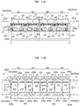
- FIG. 1A and FIG. 1B are a schematic side view and a plan view in which an illustration of a central assembly 1C of five assemblies 1A to 1E forming the conveying and sorting apparatus is omitted.
- a carry-in conveyor 2 is connected to an assembly 1A at an entrance side end portion, and a carry-out conveyor 3 is connected to an assembly 1E at an exit side end portion.
- a sorting area is set at one or a plurality of locations on a conveying path for conveying a tray T loaded with a conveyed object. In this sorting area, the conveying and sorting apparatus according to the present invention is installed.
- the sorting of the conveyed object in this conveying and sorting apparatus is carried out by tilting the conveyed tray T in one of left and right sorting directions without stopping the movement in the conveying direction, and laterally and downwardly sliding and dropping the conveyed object loaded on the tray T from on top of the tray T by gravity.
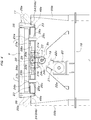
- Each assembly 1A to 1E is composed of a support shaft 7 having both ends rotatably supported by a pair of bearings 5, 6 in the conveying direction of the conveyed object, being parallel to the conveying direction of the conveyed object conveying and sorting apparatus, and horizontally located at a central position in a left-right width direction of the conveyed object conveying and sorting apparatus, a pair of front and rear tilting conveyor units 10, 11 supported by a pair of front and rear bearings 8a, 8b and 9a, 9b on this support shaft 7, respectively, and two tilting motors 12, 13 individually switching the tilting conveyor units 10, 11 between a horizontal conveying orientation and a tilted orientation.
- the bearings 5, 6 located at both ends in the conveying direction of the conveying and sorting apparatus among the pair of front and rear bearings 5, 6 of each assembly 1A to 1E are each supported above a frame 16 by one columnar support member 14, 15. Two adjacent bearings 5, 6 between two adjacent assemblies are supported on a common columnar support member 17 via a pedestal 17a.
- the winding transmission means 21 a belt transmission means composed of a transmission-side pulley 22a, a driven-side pulley 22b, and an endless belt 22c stretched between both pulleys 22a, 22b is illustrated.
- the winding transmission means may be a winding transmission means using a chain.
- Each tilting conveyor unit 10, 11 has the same structure and is composed of a structure 23 being horizontally long rectangular in plan view, a pair of left and right belt conveyors 24a, 24b for conveying the conveyed object provided to the structure 23, and side guides 25a, 25b attached along both left and right ends of the structure 23.
- the pair of left and right belt conveyors 24a, 24b are formed by stretching an endless belt 26c between a driving pulley 26a and a driven pulley 26b, and installed so that an upper conveying path portion of the endless belt 26c is exposed on an upper surface of the structure 23.
- a pair of left and right driving pulleys 26a located concentrically with each other are attached to outer end portions of a pair of left and right rotary shafts 28a, 28b supported in a left-right horizontal orientation by bearings 27a, 27b. Both rotary shafts 28a, 28b are interlockingly coupled, via rotation transmitting joints 31a, 31b, to output shafts 30a, 30b concentrically protruding to both left and right sides from a gear box 29 installed at a central position in the left-right width direction in the structure 23.
- the gear box 29 includes a drive shaft 32 protruding rearward at the central position in the left-right width direction in the structure 23 and is configured such that both output shafts 30a, 30b are interlocked and rotated in the same direction at the same speed by the rotation of the drive shaft 32.
- the drive shaft 32 is interlockingly coupled to the interlocking transmission shaft 19 (the support shaft 7 of each assembly 1A to IE) located directly below the drive shaft 32 by a winding transmission means 33.
- a belt transmission means composed of a transmission-side pulley 34a, a driven-side pulley 34b, and an endless belt 34c stretched between both pulleys 34a, 34b is illustrated.
- the winding transmission means 33 may be a winding transmission means using a chain.
- the pairs of left and right belt conveyors 24a, 24b provided to the pairs of front and rear tilting conveyor units 10, 11 of all of the assemblies 1A to 1E can be rotationally driven via the winding transmission means 33 and the gear boxes 29 from the interlocking transmission shaft 19 (the support shaft 7 of each assembly 1A to 1E) such that the tray T supported on the belt conveyors 24a, 24b is conveyed from the entrance side to the exit side of the conveying and sorting apparatus at a predetermined speed.
- the conveying path is regulated at both left and right sides of the tray T by the side guides 25a, 25b erected on both left and right sides of each tilting conveyor unit 10, 11.
- Guide rollers 35 abutting and rolling on both left and right side surfaces of the tray T are pivotally supported at both front and rear end portions in the conveying direction of the side guides 25a, 25b.
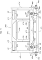
- the pair of front and rear tilting conveyor units 10, 11 provided to the assemblies 1A to 1E are supported by the interlocking transmission shaft 19 (the support shaft 7 of each assembly 1A to IE) via the pair of front and rear bearings 8a to 9b, respectively, so as to be tiltable in a direction along which both left and right end portions vertically move.
- the tilting motor 12, 13 is interlockingly coupled for every tilting conveyor unit 10, 11.
- a speed reducer equipped with a large servomotor having an overall length in the axial center direction longer than the lateral width in the conveying direction of one tilting conveyor unit 10/11 and having a large driving torque is used.
- the tilting motors 12, 13 are installed on the frame 16 so that the front and rear are reverse to each other at both left and right sides of the support shaft 7 in plan view and so that respective axial center directions become parallel to the support shaft 7.
- an output shaft 36, 37 of each tilting motor 12, 13 is attached with a transmission side timing belt pulley 38a, 39a.
- a free end portion of the output shaft 36, 37 protruding from the transmission side timing belt pulley 38a, 39a is supported by a bearing 41a, 41b attached on a mounting plate 40a, 40b supporting each tilting motor 12, 13.
- the output shaft 36, 37 is made into a doubly supported structure.
- bearings 8a, 9b located on the outer side among the pair of front and rear bearings 8a to 9b for tiltably supporting each tilting conveyor unit 10, 11 by the support shaft 7 are adjacent.
- driven side timing belt pulleys 38b, 39b paired with the transmission side timing belt pulleys 38a, 39a are loosely fitted to the support shaft 7 so as to be relatively rotatable.
- These driven side timing belt pulleys 38b, 39b and the bearings 8a, 9b adjacent on the outer side are linked and integrated by a circumferential plurality of linking bolts 42, 43.
- Timing belts 38c, 39c serving as winding transmission tools are stretched around the transmission side timing belt pulleys 38a, 39a, and driven side timing belt pulleys 38b, 39b, and then winding transmission means 44, 45 using timing belts are thus configured.
- two tilting motors 12, 13 in an orientation in which the axial center direction is parallel to the support shaft 7 are installed on the frame 16 in a point symmetrical manner with respect to a central point in the length direction of the support shaft 7 at positions where the winding transmission means 44, 45 can be configured as above.
- the mounting plate 40a, 40b supporting each tilting motor 12, 13 and the bearing 41a, 41b is mounted on the frame 16 so as to be positionally adjustable in the left-right lateral direction, and it is configured such that the tension adjustment of the timing belt 38c, 39c of the winding transmission means 44, 45 can be performed.
- the transmission-side pulley 34b of the winding transmission means 33 for transmitting the rotation of the interlocking transmission shaft 19 (the support shaft 7 of each assembly 1A to IE) to the belt conveyors 24a, 24b of the tilting conveyor unit 10, 11 is attached to the support shaft 7 at a position adjacent to the inside of the driven side timing belt pulley 38b, 39b of the winding transmission means 44, 45, as shown in FIG. 3 .
- the pairs of left and right belt conveyors 24a, 24b of the pair of front and rear tilting conveyor units 10, 11 provided to each assembly 1A to 1E are such that, by operating the one conveyor driving motor 20, its rotational force is transmitted to the driving pulleys 26a of the belt conveyors 24a, 24b via the winding transmission means 21 and the interlocking transmission shaft 19, and the winding transmission means 33, gear boxes 29, and rotary shafts 28a, 28b respectively corresponding to the tilting conveyor units 10, 11, and the endless belts 26c enter an operating state of rotating in a predetermined direction at a predetermined speed.
- the tilting motors 12, 13 are stopped with the tilting conveyor units 10, 11 of all of the assemblies 1A to 1E being in the horizontal conveying orientation as shown in FIG. 5 , so that the tilting conveyor units 10, 11 are held in the horizontal conveying orientation by the function of the tilting motors 12, 13 and do not swing about the support shaft 7/the interlocking transmission shaft 19 by gravity.
- the conveyor driving motor 20 is operated as above to interlockingly rotationally drive the belt conveyors 24a, 24b in a predetermined conveying direction, and then the tray T loaded with the conveyed object sent in from the carry-in conveyor 2 shown in FIG. 1A and FIG. 1B can be conveyed toward the carry-out conveyor 3 at a constant speed and sent out onto the carry-out conveyor 3.
- the target tilting conveyor unit 10/11 can be tilted about the support shaft 7 (the interlocking transmission shaft 19) in a predetermined direction by a rotation angle of the driven side timing belt pulley 38b/39b.
- the tilting motor 12/13 of the tilting conveyor unit 10/11 is reversely rotated by the rotation angle at the time of tilting operation, and the tilting conveyor unit 10/11 can be returned from the tilted orientation to the original horizontal conveying orientation.
- the conveyance of the tray T is continued by the belt conveyors 24a, 24b provided to each tilting conveyor unit 10/11.
- the entire area of the tilting conveyor units 10/11 switched to the tilted orientation moves in the traveling direction of the tray T according to the conveying speed of the tray T, and the orientation of each tilting conveyor unit 10/11 is controlled such that the tilting conveyor units 10/11 having departed rearward from the area are sequentially returned from the tilted orientation to the horizontal orientation.
- the tilting conveyor units 10/11 within the area supporting the tray T which completed the discharge of the conveyed object W for sorting are returned and swung from the tilted orientation to the horizontal orientation.
- Each tilting conveyor unit 10/11 on the downstream side of the area supporting the tray T is once swung downward from the horizontal orientation to an angle continuing with the tilting conveyor unit 10/11 in the process of returning to the horizontal orientation directly therebehind and then returned and swung to the horizontal orientation integrally with the tilting conveyor unit 10/11 in the process of returning to the horizontal orientation directly therebehind.
- the tray T which completed the discharge of the conveyed object W for sorting is returned to the horizontal orientation while traveling at a predetermined speed, and is finally sent out onto the carry-out conveyor 3 in the horizontal orientation.
- the both left and right side guides 25a, 25b of each tilting conveyor unit 10/11 are configured as follows in accordance with the present invention. That is, as shown in FIG. 8 to FIG. 10 , the both left and right side guides 25a, 25b are each composed of a horizontally long rectangular inner side plate 47a facing the conveying path of the tray and a band-shaped upper side plate 47b, both front and rear side plates 47c, 47d connecting the inner side plate 47a and the upper side plate 47b, a bearing plate 47e horizontally fixed to the inner side plate 47a below the upper side plate 47b, a reinforcing angle member 47f horizontally fixed to an outer surface closer to a lower end of the inner side plate 47a, and a pair of front and rear reinforcing support plates 47g, 47h vertically fixed between the reinforcing angle member 47f and the bearing plate 47e.
- a lower side of the inner side plate 47a is bent outward to form a bent bottom plate portion 47i fixed to the both front and rear side plates 47c, 47d.
- the guide rollers 35 pivotally supported by the side guide 25a, 25b are configured to be pivotally supported by vertical support shafts respectively above the bearing plate 47e and have peripheral portions exposed inward from opening portions 47j formed in the inner side plate 47a.
- the side guides 25a, 25b configured as above have lower end portions attached to both left and right sides of the structure 23 of the tilting conveyor unit 10/11 by pairs of front and rear bolts and nuts 49a, 49b concentric with each other and are pivotally supported so as to be swingable in the left-right lateral direction with bolts of the bolts and nuts 49a, 49b as support shafts.
- the structure 23 is a flat box shaped frame structure which is supported by the support shaft 7 so as to be swingable left and right and provided with a pair of left and right belt conveyors 24a, 24b.
- the side guides 25a, 25b are swingable in the left and right lateral direction with the bolts of the bolts and nuts 49a, 49b as support shafts between a vertical standing orientation in which the lower end portions of the inner side plates 47a of the side guides 25a, 25b abut the both left and right side plate portions 48c of the structure 23 and a tilted orientation in which the bent bottom plate portions 47i abut the both left and right side plate portions 48c of the structure 23.
- an opening restricting means 50 receiving, at a certain angle, the side guides 25a, 25b opened outward from the vertical standing orientation is formed by the both left and right side plate portions 48c on the structure 23 side and the bent bottom plate portions 47i on the side guides 25a, 25b side.
- An orientation holding means 51 holding the side guides 25a, 25b configured as above in the vertical standing orientation is formed by the both left and right side plate portions 48c of the structure 23, the inner side plates 47a of the side guides 25a, 25b, and pairs of front and rear bolts and nuts 52, 53 penetrating through, in the left and right horizontal direction, vertical plate portions of the reinforcing angle members 47f overlapping the inner side plates 47a, and fixing the inner side plates 47a of the side guides 25a, 25b to the both left and right side plate portions 48c of the structure 23.
- all of bolts 52a, 53a and double nuts 52b, 52c and 53b, 53c may be made of synthetic resin.
- the magnitude of the outward external force allowing the outward opening of the side guides 25a, 25b is determined by the breaking strength of the synthetic resin bolts 52a, 53a used for the bolts and nuts 52, 53.
- the breaking strength determined according to the shaft diameter and the material, etc., of the synthetic resin bolts 52a, 53a has only to be selected such that the side guides 25a, 25b can be held in the vertical standing orientation until a predetermined level or more of outward pressing force acts.
- the pair of front and rear bolts and nuts 52, 53 are arranged between the pair of front and rear bolts and nuts 49a, 49b pivotally supporting the side guide 25a, 25b and at two front and rear places relatively close to the bolts and nuts 49a, 49b.
- the pair of front and rear bolts and nuts 52, 53 may be arranged at two front and rear places away from the bolts and nuts 49a, 49b further inward or may be arranged at one place at the center between the bolts and nuts 49a, 49b or at a total of three places, one place at the center between the bolts and nuts 49a, 49b and two places on both sides.
- the pair of front and rear bolts and nuts 52, 53 are desirably arranged between the pair of front and rear bolts and nuts 49a, 49b and at two front and rear places relatively close to the bolts and nuts 49a, 49b.
- the side guides 25a, 25b are attached to the both left and right sides of the structure 23 of the tilting conveyor unit 10/11 as described above, when the tray T continuing forward traveling by the belt conveyors 24a, 24b of each tilting conveyor unit 10/11 travels in a state of being always received by the pair of front and rear guide rollers 35 of the side guide 25a/25b that becomes the lower side of the tilt of each tilting conveyor unit 10/11 at the time of sorting operation involving the swinging of each tilting conveyor unit 10/11 from the horizontal orientation to the tilted orientation and the opposite swinging from the tilted orientation to the horizontal orientation, no unreasonable outward force from the tray T side acts on the side guide 25a/25b, and each side guide 25a/25b is held in the vertical standing orientation with respect to the structure 23 by the pair of front and rear bolts and nuts 52, 53 of the orientation holding means 51.
- the synthetic resin bolt(s) 52a/53a of both of the pair of front and rear bolts and nuts 52, 53 of the orientation holding means 51 or one of the bolts and nuts which is closer to the place receiving the pressing force are/is broken by the pressing force at this time, and the entirety or one of the front and rear sides of the side guide 25a/25b on the lower side of the tilt is freed, and the side guide 25a/25b is opened outward around the bolts and nuts (support shafts) 49a, 49b.
- the side guide 25a/25b is prevented from being significantly deformed and damaged by the pressing force.
- the overall configuration of the conveying and sorting apparatus provided with the tilting conveyor units 10, 11 to which the side guides 25a, 25b are attached in accordance with the present invention is not limited to the configuration of one embodiment described above.
- a driving means for tilting each tilting conveyor unit 10, 11, a type of the conveyor for moving the tray T on each tilting conveyor unit 10, 11 and a driving method of the conveyor can adopt any configuration irrespective of the present invention.
- the sorting direction of the tilting conveyor units 10, 11 is limited to one of the left and right sides, of the side guides 25a, 25b, only the side guide 25a/25b on the sorting direction side has only to be configured according to the present invention.
- the side guides 25a, 25b on the both left and right sides of the tilting conveyor units 10, 11 are configured according to the present invention. This is because it is also considered that, when the front end corner of the tray T violently collides with the side guide 25a/25b on the lower side of the tilt, the tray T is significantly tilted on the traveling path by the reaction and the rear end corner violently collides with the side guide 25a/25b on the upper side of the tilt.
- the side guide 25a/25b on the upper side of the tilt is made free and opened outward by configuring the side guides 25a, 25b on the both left and right sides according to the present invention in advance, and a significant deformation and damage can be prevented beforehand.
- the tilting conveyor unit 10/11 including the side guide 25a/25b in the opened orientation is returned to the horizontal orientation.
- This abnormal event needs to be detected swiftly by a detecting means to urgently stop the conveying and sorting apparatus and notify a facility manager by a warning buzzer/light, etc.
- a detecting means for detecting the side guide 25a/25b released from the holding in the standing orientation by the orientation holding means (51) and opened.
- the detecting means is desirably configured as follows.
- the detecting means can be formed by a photoelectric sensor 54 irradiating a detection light beam 54c detecting the side guide(s) 25a, 25b in an opened state from one end to the other end of the group of the plurality of tilting conveyor units 10/11 arranged in a straight line (the illustrated example is the entire conveying and sorting apparatus).
- the photoelectric sensor 54 besides a photoelectric sensor formed by a light projector 54a irradiating the detection light beam 54c and a light receiver 54b receiving the detection light beam 54c, a reflective photoelectric sensor in which a light projector/receiver set provided with a light projector and a light receiver is used in place of the light projector 54a and a reflector is arranged in place of the light receiver 54b can be used.
- the reflective photoelectric sensor when the reflective photoelectric sensor is used, the reflector can be attached to a side surface on the side where the light projector 54a is located of each side guide 25a, 25b, without arranging the reflector in place of the light receiver 54b.
- an abnormality detection is turned ON when a situation occurs that the detection light beam from the light projector is blocked by the side guide 25a, 25b in an abnormal orientation of being opened and the light receiver does not receive the light beam.
- the abnormality detection is turned ON when the detection light beam from the light projector is reflected by the reflector of the side guide 25a, 25b in the abnormal orientation of being opened and the light receiver receives the reflected light beam.
- the light projector 54a irradiating the detection light beam 54c can be attached, via a supporting bracket, inside an upper end portion of a columnar support member 55a erected on the frame 16 on one end side of the entire conveying and sorting apparatus, for example, an end portion on the side where the carry-in conveyor 2 is located.
- the light receiver 54b (or the reflector) receiving the detection light beam 54c can be attached, via a supporting bracket, inside an upper end portion of a columnar support member 55b erected on the frame 16 on the other end side of the entire conveying and sorting apparatus.
- the position of the detection light beam 54c is desirably configured to be a position close to the outside of an area on the lower end side of the side guide 25a, 25b in the vertical standing orientation so that, even if the tilt angle of the side guide 25a, 25b is freed and opened outward slightly changes, that side guide 25a, 25b can be detected.
- the shaft portions of the synthetic resin bolts 52a, 53a and the double nuts 52b, 52c and 53b, 53c screw-fitted thereto protruding inside the side guide 25a, 25b of the pair of front and rear bolts and nuts 52, 53 in the above embodiment are coupled to each other by a scatter preventing cord-like body 56.
- a flexible thin metal wire rod generally called a wire and a chain, etc.
- the cord-like body 56 has both ends attached with a mounting plate 57.
- the mounting plate 57 is made of a metal thin plate provided with a through hole through which the shaft portion of the synthetic resin bolt 52a, 53a of the bolt and nut 52, 53 is inserted, and is sandwiched and fixed between the double nuts 52b, 52c and between the double nuts 53b and 53c.
- the cord-like body 56 has an end portion fixed with a terminal plate 56a by caulking, and the terminal plate 56a is attached to the mounting plate 57 by a fixing tool 56b such as a screw nut or rivet.
- the plate portion 48c on the structure 23 side and the plate portion 47a on the side guide 25a, 25b side linked by the bolts and nuts 52, 53 are provided with two through holes 58a, 58b so as to be penetrated concentrically with each other at positions near the both bolts and nuts 52, 53.
- An intermediate portion of the scatter preventing cord-like body 56 whose both ends are coupled to the bolts and nuts 52, 53 as described above bypasses the inside of the structure 23 through the two through holes 58a, 58b.
- the other end of the cord-like body 56 to which the mounting plate 57 is attached only at one end via the terminal plate 56a is inserted inside the structure 23 from one of the through holes 58a, and then the other end of the cord-like body is inserted through the side guide 25a, 25b side from the other through hole 58b, and finally the terminal plate 56a and the mounting plate 57 can be attached to the other end of the cord-like body 56.
- the through holes 58a, 58b have an inner diameter through which the terminal plates 56a can be inserted, the terminal plates 56a can be attached to both ends of the cord-like body 56 in advance.
- the mounting plates 57 can also be attached to both ends of the cord-like body 56 via the terminal plates 56a in advance.
- the mounting plates 57 attached, via the terminal plates 56a, to both ends of the cord-like body 56 withdrawn inside the side guide 25a, 25b from each through hole 58a, 58b are sandwiched and fixed between the double nuts 52b, 52c and between the double nuts 53b, 53c protruding inside the side guide 25a, 25b of the bolts and nuts 52, 53.
- the side guide 25a, 25b receives an outward overload, breaks the synthetic resin bolts 52a, 53a of the bolts and nuts 52, 53, and opens around the bolts and nuts 49a, 49b (support shafts). Since the break of the synthetic resin bolts 52a, 53a occurs between their head portions and shaft portions, the head portions of the synthetic resin bolts 52a, 53a located on the structure 23 side drop inside the structure 23 and are received, as shown in FIG. 13B .
- the nut side broken pieces of both bolts and nuts 52, 53 are connected to each other by the cord-like body 56, jump out from the inside of the side guide 25a, 25b by an extra length of the cord-like body 56, and brought into a state where the cord-like body 56 is suspended by the cord-like body 56 from the two through holes 58a, 58b through which the cord-like body 56 is inserted. That is, the nut side broken pieces no longer violently scatter when the bolts and nuts 52, 53 are broken.
- two through holes 59a, 59b are provided to the reinforcing angle member 47f disposed above the bolts and nuts 52, 53 in the side guide 25a, 25b, and the intermediate portion of the cord-like body 56 whose both ends are coupled to the double nuts 52b to 53c side of the both bolts and nuts 52, 53 can bypass the upper side of the reinforcing angle member 47f (the side opposite to the side where the bolts and nuts 52, 53 are located) via the two through holes 59a, 59b.
- the inner diameter of the through holes 58a, 58b or 59a, 59b for allowing the cord-like body 56 to bypass is desirably set to be an inner diameter through which the terminal plates 56a fixed to the end portions of the cord-like body 56 in advance can be inserted.
- the terminal plates 56a can be omitted.
- the conveying and sorting apparatus of the present invention can be utilized as a conveyed object conveying and sorting apparatus such that the conveyed object is loaded and conveyed on a dedicated conveying tray and also required to be sorted automatically according to the destination, as in the luggage conveyance and sorting at airports.
Abstract
Description
- The present invention relates to a conveying and sorting apparatus capable of laterally sliding and sorting a conveyed object by gravity at a sorting position set on a conveying path of the conveyed object.
- As the conveying and sorting apparatus as described above, as described in Patent Literature 1, there is known a conveying and sorting apparatus including a plurality of tilting conveyor units arranged in a row in a conveying direction, each of the tilting conveyor units supported so as to be swingable left and right about a support shaft parallel to the conveying direction of the conveyed object between a horizontal conveying orientation and a tilted orientation for discharging the conveyed object laterally with respect to the conveying direction of the conveyed object by gravity, and having side guides erected on both sides in a left-right swinging direction and regulating a conveying path width when the tilting conveyor unit is in the horizontal orientation. Such a conveying and sorting apparatus is used in such a manner that a tray having a height not lower than the side guides is used together instead of directly placing and conveying the conveyed object on conveying conveyors provided to each tilting conveyor unit, and the conveyed object placed on the tray is slid on the tray by tilting the tilting conveyor units from the horizontal orientation to the tilted orientation and discharged laterally so as to pass above the side guide, and then the tilting conveyor units supporting the tray are returned from the tilted orientation to the original horizontal orientation.
- Patent Literature 1: Japanese Translation of International Application (Kohyo) No.
2015-501770 - In the conveying and sorting apparatus described in Patent Literature 1 above, when the switching of the tilting conveyor units to the tilted orientation for starting the above-described sorting operation and the switching of the tilting conveyor units to the horizontal orientation after sorting completion are performed without stopping the tray, among the tilting conveyor units arranged in a row in the conveying direction, a plurality of tilting conveyor units which are located in an area supporting the entire traveling tray and on the traveling direction side of the tray farther than this area need to be switched in a timely manner to the tilted orientation or the horizontal orientation. However, even if the switching of the tilting conveyor units to the horizontal orientation after the sorting completion is performed in a timely manner as set, slight variations in the traveling speed of the tray occur due to a contact of the tray to the side guide on the lower side of the tilt and a change in the orientation of the tray within the conveying path width between the both left and right side guides, etc. As the conveying speed of the tray increases, the variations in the traveling speed of the tray also increase. As a result, there has been a problem that such an accident occurs that the side guide on the lower side of the tilt of the tilting conveyor unit in the process of returning and swinging from the tilted orientation to the horizontal orientation collides with a front end corner of the traveling tray and then the side guide on the lower side of the tilt is forcibly bent outward or the front end corner of the tray is damaged.
- The present invention proposes a conveying and sorting apparatus capable of solving the conventional problems as described above. Described by giving reference signs in parentheses used in the description of embodiments described below in order to facilitate understanding the relationship with the embodiments, the conveying and sorting apparatus according to the present invention is a conveying and sorting apparatus including a plurality of tilting conveyor units (10, 11) arranged in a row in a conveying direction, each of the tilting conveyor units (10, 11) supported so as to be swingable left and right about a support shaft (7, 19) parallel to a conveying direction of a conveyed object between a horizontal conveying orientation and a tilted orientation for discharging the conveyed object laterally with respect to the conveying direction of the conveyed object by gravity, and each of the tilting conveyor units (10, 11) having side guides (25a, 25b) erected on both sides in a left-right swinging direction and regulating a conveying path width, in which, of the side guides (25a, 25b), at least the side guide (25a/25b) on the side of swinging to the tilted orientation is supported so as to be openable to the swinging direction side toward the tilted orientation with respect to a structure (23) of the tilting conveyor unit (10, 11), and is juxtaposed with an orientation holding means (51) holding the side guide (25a/25b) in a standing orientation until load of a certain level or more in the opening direction acts on the side guide (25a/25b).
- According to the configuration of the present invention described above, even when such a situation occurs that the side guide on the lower side of the tilt of the tilting conveyor unit in the process of returning and swinging from the tilted orientation to the horizontal orientation collides with the front end corner of the traveling tray, if the orientation holding means is configured such that an outward load acting on the side guide at that time overcomes the holding force of the orientation holding means, the side guide opens outward by overcoming the holding force of the orientation holding means by the collision of the front end corner of the tray, and the impact received from the tray at that time can be absorbed. Accordingly, such an accident that the side guide on the lower side of the tilt is forcibly bent outward by the tray or the front end corner of the tray is damaged as in the conventional case can be avoided.
- When the above present invention is carried out, specifically, both of the left and right side guides (25a, 25b) can be supported so as to be openable outward with respect to the structure (23) of the tilting conveyor unit (10, 11), and the left and right side guides (25a, 25b) can also be juxtaposed with orientation holding means (51) holding the side guides (25a, 25b) in a standing orientation until load of a certain level or more in the opening direction acts on the side guides (25a, 25b). According to this configuration, although as a matter of course in the case where the tilting conveyor unit is configured to be swingable to both left and right sides and the present invention is carried out as a conveying and sorting apparatus capable of sorting to both left and right sides of the tilting conveyor unit, even in the case where the tilting conveyor unit is configured to be swingable to only either side and the present invention is carried out as a conveying and sorting apparatus capable of sorting to only either left or right side of the tilting conveyor unit, the side guide on the upper side of the tilt held in the standing orientation opens outward by an overload from the tray and absorbs the overload when such a situation occurs that a corner on the rear end side of the tray strongly presses the side guide on the upper side of the tilt outward when the front end corner of the traveling tray is caught by the lower side guide of the tilting conveyor unit in the process of swinging for returning from the tilted orientation to the horizontal orientation and the tray is slanted on the conveying surface. Thus, a deformation of the side guide on the upper side of the tilt or damage to the rear end corner of the tray can be avoided beforehand.
- The orientation holding means (51) may have any configuration. For example, the orientation holding means (51) may be such that the structure (23) and the side guide (25a, 25b) are provided with plate portions (47a, 48a/47b, 48b) overlapping each other in the front-rear direction (conveying direction), and at least one of bolt holes provided to the both plate portions is a cut hole being open to the outside, and the side guide (25a, 25b) is fixed in the standing orientation with respect to the structure (23) by a bolt and nut penetrating through the bolt holes of the both plate portions in the front-rear direction (conveying direction). In this case, the bolt separates outward from the cut hole to make the side guide free when an external force having a magnitude exceeding fastening friction based on a fastening force by the bolt and nut acts on the side guide. Thus, the outward load acting on the side guide can be absorbed.
- For the orientation holding means as described above, it is also possible to use an orientation holding means (51) which is configured such that the structure (23) and the side guide (25a, 25b) are provided with plate portions (47a, 48c) overlapping each other in the left-right lateral direction, and a bolt and nut (52) penetrating through and linking the both plate portions (47a, 48c) in the left-right lateral direction is provided, and at least a bolt (52a) of the bolt and nut (52) is made of synthetic resin, and the synthetic resin portion of the bolt and nut (52) is broken when load of a certain level or more in the opening direction acts on the side guide (25a, 25b). In this orientation holding means, the synthetic resin part of the bolt and nut is broken when load of a certain level or more in the opening direction acts on the side guide, and the side guide is switched to a free state. As compared with the case of adjusting the load at the time when the side guide is freed, by the degree of fastening of the bolt and nut as in the former orientation holding means, the magnitude of the load at the time when the side guide is freed is determined by at least a breaking strength in the axial direction of the synthetic resin bolt. Thus, the object can be achieved only by selecting the synthetic resin bolt to be used, and assembling of the side guide is simplified and facilitated, and the intended object can be achieved reliably.
- When a very large external force acts outward on the side guide and the synthetic resin bolt of the bolt and nut is broken, the break occurs between a head portion and a shaft portion of the synthetic resin bolt. Thus, a broken part located on the structure interior side of the plate portion on the structure side of the both plate portions linked by the bolt and nut remains on the structure interior side, and a broken part located outside the plate portion on the side guide side violently scatters toward the outside of the side guide. As a matter of course, the outside of the side guide may be a structure which is covered with a cover plate, but it is desirable not to provide the cover plate because the attaching and detaching work of the cover plate is required in the mounting work of the side guide to the structure, the assembling work of the orientation holding means, or in the maintenance and inspection work. When the cover plate is not provided, the broken part violently scatters to the outside from the side guide when a situation occurs that the bolt and nut of the orientation holding means is broken as described above. When the broken part is a small bolt head portion, there is a high possibility of mixing in the peripheral equipment to cause failure. When the shaft portion of the synthetic resin bolt and the nut screw-fitted thereto scatter as the broken parts, there is a high possibility of posing a danger to nearby workers and visitors, etc., because the mass is large.
- In order that the problems as above can also be solved, the synthetic resin bolt (52a) of the bolt and nut (52) can be arranged in an orientation in which a bolt head portion is located on the structure interior side of the plate portion (48c) on the structure (23) side of the both plate portions (47a, 48c), and a bolt and nut part (a shaft portion of the synthetic resin bolt (52a) and a nut (52b, 52c) screw-fitted thereto) located outside the plate portion (47a) on the side guide (25a, 25b) side of the bolt and nut (52) can be linked to one end side of a scatter preventing cord-like body (56), and the other end side of the cord-like body (56) can be locked to the structure (23) or the side guide (25a, 25b).
- When the above configuration is carried out, the assembling work of the scatter preventing cord-like body is simplified and facilitated if the one end side of the scatter preventing cord-like body (56) is attached with a mounting plate (57) through which the bolt (52a) of the bolt and nut (52) penetrates and which is sandwiched and fixed by a double nut (52b, 52c) used for the bolt and nut part.
- When the side guide is supported so as to be swingable left and right, generally, the side guide is pivotally supported by a pair of concentric front and rear support shafts (49a, 49b). The bolt and nut (52, 53) is desirably provided in a front and rear pair between the both support shafts (49a, 49b). In this case, the scatter preventing cord-like body (56) linked to the bolt and nut parts located outside the plate portion (47a) on the side guide (25a, 25b) side of the both bolts and nuts (52, 53) can be configured to be connected so as to form a single cord on the side opposite to the side where the bolt and nut parts are located of the structure (23) or the side guide (25a, 25b), through two through holes (58a, 58b) provided to the structure (23) or the side guide (25a, 25b). According to this configuration, resultantly, not only can the scattering of the broken parts at the time of breaking of the two front and rear bolts and nots (52, 53) be prevented by the single cord-like body, but also labor and the addition of extra parts are avoided as in the case where the cord-like body is fixed to the structure or the side guide via a locking fitting.
- Further, it is desirable to juxtapose an opening restricting means (50) to receive, at a certain angle, the side guide (25a, 25b) released from the holding in the standing orientation by the orientation holding means (51) and opened. According to this configuration, as compared with such a configuration that the side guide released from the holding in the standing orientation by the orientation holding means is allowed to be opened to the limit of hanging down from the side of the tilting conveyor unit, not only can the opened side guide be prevented from being caught by the related facility such as a chute for taking over the conveyed object juxtaposed aside of the tilting conveyor units, but also an accident can be prevented that results from falling of the tray from on top of the tilting conveyor units or a large protrusion of the front end portion of the tray from the conveying path.
- When the holding in the standing orientation of the side guide by the orientation holding means is released, the tilting conveyor unit is returned to the horizontal orientation with the side guide opened outward. If a detecting means to detect the opened side guide at this time is juxtaposed, various inconvenient situations which may occur when the operation is continued as it is can be prevented beforehand by automatically stopping the conveying and sorting apparatus itself based on a detection signal of the detecting means, and it also becomes possible, by actuating an alarm or emergency light based on the detection signal, to notify a nearby worker, etc., of an abnormality to quickly take necessary measures. The detecting means in this case may be juxtaposed for each tilting conveyor unit. However, it is also helpful in cost reduction that the detecting means is formed by a photoelectric sensor (54) irradiating a detection light beam (45c) detecting the opened side guide (25a, 25b) from one end toward the other end of a group of the plurality of tilting conveyor units (10, 11) arranged in a row in the conveying direction.
-
- [
FIG. 1] FIG. 1A is a partially omitted side view of a conveying and sorting apparatus, andFIG. 1B is a plan view of the same. - [
FIG. 2] FIG. 2 is a side view of a main part showing an exit side area of the conveying and sorting apparatus. - [
FIG. 3] FIG. 3 is a plan view of the main part showing the exit side area of the conveying and sorting apparatus. - [
FIG. 4] FIG. 4 is a partially cutaway front view showing the exit side of the conveying and sorting apparatus. - [
FIG. 5] FIG. 5 is a longitudinal sectional rear view showing each assembly forming the conveying and sorting apparatus. - [
FIG. 6] FIG. 6 is a front view showing a sorting operation of a tilting conveyor unit. - [
FIG. 7] FIG. 7 is a schematic side view illustrating conveying and sorting operation of the conveying and sorting apparatus. - [
FIG. 8] FIG. 8 is a longitudinal sectional front view showing a main part of an embodiment of the present invention. - [
FIG. 9] FIG. 9 is a side view showing the main part of the embodiment of the present invention. - [
FIG. 10] FIG. 10 is a partial cross sectional plan view showing the main part of the embodiment of the present invention. - [
FIG. 11] FIG. 11 is an outer side view of a side guide showing a second embodiment of the present invention. - [
FIG. 12] FIG. 12 is a cross sectional plan view of a main part ofFIG. 11 . - [
FIG. 13] FIG. 13A is a longitudinal sectional front view showing a normal condition of the main part ofFIG. 11 , andFIG. 13B is a longitudinal sectional front view showing an abnormal condition of the main part ofFIG. 11 . -
FIG. 1A and FIG. 1B are a schematic side view and a plan view in which an illustration of a central assembly 1C of fiveassemblies 1A to 1E forming the conveying and sorting apparatus is omitted. A carry-inconveyor 2 is connected to anassembly 1A at an entrance side end portion, and a carry-outconveyor 3 is connected to anassembly 1E at an exit side end portion. In this embodiment, a sorting area is set at one or a plurality of locations on a conveying path for conveying a tray T loaded with a conveyed object. In this sorting area, the conveying and sorting apparatus according to the present invention is installed. The sorting of the conveyed object in this conveying and sorting apparatus is carried out by tilting the conveyed tray T in one of left and right sorting directions without stopping the movement in the conveying direction, and laterally and downwardly sliding and dropping the conveyed object loaded on the tray T from on top of the tray T by gravity. - Hereinafter, a detailed structure of each
assembly 1A to 1E is described based onFIG. 2 to FIG. 5 . Eachassembly 1A to 1E is composed of asupport shaft 7 having both ends rotatably supported by a pair ofbearings tilting conveyor units rear bearings support shaft 7, respectively, and two tiltingmotors conveyor units bearings rear bearings assembly 1A to 1E are each supported above aframe 16 by onecolumnar support member adjacent bearings columnar support member 17 via apedestal 17a. - Between the two adjacent assemblies of the
assemblies 1A to IE, end portions of thesupport shafts 7 are concentrically interlockingly coupled to each other by a rotation transmitting joint 18, and a singleinterlocking transmission shaft 19 continuing over the overall length of the conveying and sorting apparatus is formed. As shown inFIG. 1A, FIG. 1B , andFIG. 4 , at a free end of thesupport shaft 7 of theassembly 1E located at the exit side end portion of the conveying and sorting apparatus, oneconveyor driving motor 20 supported by theframe 16 outside theassembly 1E is interlockingly coupled by a vertical winding transmission means 21. As the winding transmission means 21, a belt transmission means composed of a transmission-side pulley 22a, a driven-side pulley 22b, and anendless belt 22c stretched between bothpulleys - Each tilting
conveyor unit structure 23 being horizontally long rectangular in plan view, a pair of left andright belt conveyors structure 23, andside guides structure 23. The pair of left andright belt conveyors endless belt 26c between a drivingpulley 26a and a drivenpulley 26b, and installed so that an upper conveying path portion of theendless belt 26c is exposed on an upper surface of thestructure 23. A pair of left and right drivingpulleys 26a located concentrically with each other are attached to outer end portions of a pair of left andright rotary shafts bearings rotary shafts rotation transmitting joints output shafts gear box 29 installed at a central position in the left-right width direction in thestructure 23. - The
gear box 29 includes adrive shaft 32 protruding rearward at the central position in the left-right width direction in thestructure 23 and is configured such that bothoutput shafts drive shaft 32. Thedrive shaft 32 is interlockingly coupled to the interlocking transmission shaft 19 (thesupport shaft 7 of eachassembly 1A to IE) located directly below thedrive shaft 32 by a winding transmission means 33. As the winding transmission means 33, a belt transmission means composed of a transmission-side pulley 34a, a driven-side pulley 34b, and anendless belt 34c stretched between bothpulleys - With the above configuration, by operating the one
conveyor driving motor 20 installed at the exit side of the conveying and sorting apparatus, the pairs of left andright belt conveyors tilting conveyor units assemblies 1A to 1E can be rotationally driven via the winding transmission means 33 and thegear boxes 29 from the interlocking transmission shaft 19 (thesupport shaft 7 of eachassembly 1A to 1E) such that the tray T supported on thebelt conveyors conveyor unit Guide rollers 35 abutting and rolling on both left and right side surfaces of the tray T are pivotally supported at both front and rear end portions in the conveying direction of the side guides 25a, 25b. - The pair of front and rear
tilting conveyor units assemblies 1A to 1E are supported by the interlocking transmission shaft 19 (thesupport shaft 7 of eachassembly 1A to IE) via the pair of front andrear bearings 8a to 9b, respectively, so as to be tiltable in a direction along which both left and right end portions vertically move. In order to switch the tiltingconveyor unit FIG. 5 ) supporting and conveying the tray T and the tilted orientation tilted about thesupport shaft 7, for example, about 45 degrees, in one of the left and right directions as shown inFIG. 6 , the tiltingmotor conveyor unit motors tilting conveyor unit 10/11 and having a large driving torque is used. Thus, as shown inFIG. 3 , the tiltingmotors frame 16 so that the front and rear are reverse to each other at both left and right sides of thesupport shaft 7 in plan view and so that respective axial center directions become parallel to thesupport shaft 7. - More specifically, an
output shaft motor timing belt pulley output shaft timing belt pulley bearing plate motor output shaft bearings support shaft 7 of eachassembly 1A to IE,bearings rear bearings 8a to 9b for tiltably supporting each tiltingconveyor unit support shaft 7 are adjacent. Further inside thebearings timing belt pulleys support shaft 7 so as to be relatively rotatable. These driven side timing belt pulleys 38b, 39b and thebearings bolts belts timing belt pulleys motors support shaft 7 are installed on theframe 16 in a point symmetrical manner with respect to a central point in the length direction of thesupport shaft 7 at positions where the winding transmission means 44, 45 can be configured as above. - The mounting
plate motor bearing frame 16 so as to be positionally adjustable in the left-right lateral direction, and it is configured such that the tension adjustment of thetiming belt side pulley 34b of the winding transmission means 33 for transmitting the rotation of the interlocking transmission shaft 19 (thesupport shaft 7 of eachassembly 1A to IE) to thebelt conveyors conveyor unit support shaft 7 at a position adjacent to the inside of the driven sidetiming belt pulley FIG. 3 . - An example of a method of using the conveying and sorting apparatus configured as above will be described. As described above, the pairs of left and
right belt conveyors tilting conveyor units assembly 1A to 1E are such that, by operating the oneconveyor driving motor 20, its rotational force is transmitted to the drivingpulleys 26a of thebelt conveyors transmission shaft 19, and the winding transmission means 33,gear boxes 29, androtary shafts conveyor units endless belts 26c enter an operating state of rotating in a predetermined direction at a predetermined speed. - On the other hand, the tilting
motors conveyor units assemblies 1A to 1E being in the horizontal conveying orientation as shown inFIG. 5 , so that the tiltingconveyor units motors support shaft 7/the interlockingtransmission shaft 19 by gravity. Accordingly, with the tiltingconveyor units assemblies 1A to 1E held in the horizontal conveying orientation, theconveyor driving motor 20 is operated as above to interlockingly rotationally drive thebelt conveyors conveyor 2 shown inFIG. 1A and FIG. 1B can be conveyed toward the carry-outconveyor 3 at a constant speed and sent out onto the carry-outconveyor 3. - When a specific
tilting conveyor unit belt conveyors conveyor units assemblies 1A to 1E are operated as above, the tiltingmotor 12/13 of the tiltingconveyor unit 10/11 to be switched to the tilted orientation is operated and the rotation of itsoutput shaft 36/37 is transmitted to thestructure 23 of the target tiltingconveyor unit 10/11 through the transmission sidetiming belt pulley 38a/39a, thetiming belt 38c/39c, and the driven sidetiming belt pulley 38b/39b of the winding transmission means 44/45 and via thebearing 8a/9b linked and integrated by the linkingbolts 42/43. Thereby, the target tiltingconveyor unit 10/11 can be tilted about the support shaft 7 (the interlocking transmission shaft 19) in a predetermined direction by a rotation angle of the driven sidetiming belt pulley 38b/39b. When the tiltingconveyor unit 10/11 in the tilted orientation is returned to the original horizontal conveying orientation, the tiltingmotor 12/13 of the tiltingconveyor unit 10/11 is reversely rotated by the rotation angle at the time of tilting operation, and the tiltingconveyor unit 10/11 can be returned from the tilted orientation to the original horizontal conveying orientation. - When the conveyed object loaded on the tray T sent from the carry-in
conveyor 2 is the target to be sorted at a certain place of the conveying and sorting apparatus, as shown inFIG. 7 , at the point in time at which the tray T travels a certain distance from the carry-inconveyor 2, the required number of tiltingconveyor units 10/11 located in an area supporting the tray T and on the downstream side of this area are swung from the horizontal orientation toward the sorting side to be switched to the tilted orientation, and the traveling tray T, which the tilting conveyor units support, is tilted to the sorting side by a required angle. As a result, the conveyed object W on the tray T slides on the tray T toward the lower side of the tilt by gravity and then slips off from on top of the tray T. Generally, achute 46 taking over the conveyed object W slipping off from on top of the tray T in the tilted orientation and guiding the object onto a target handling table is juxtaposed. - Even during the above-described sorting operation, the conveyance of the tray T is continued by the
belt conveyors conveyor unit 10/11. Thus, the entire area of the tiltingconveyor units 10/11 switched to the tilted orientation moves in the traveling direction of the tray T according to the conveying speed of the tray T, and the orientation of each tiltingconveyor unit 10/11 is controlled such that the tiltingconveyor units 10/11 having departed rearward from the area are sequentially returned from the tilted orientation to the horizontal orientation. Then, the tiltingconveyor units 10/11 within the area supporting the tray T which completed the discharge of the conveyed object W for sorting are returned and swung from the tilted orientation to the horizontal orientation. Each tiltingconveyor unit 10/11 on the downstream side of the area supporting the tray T is once swung downward from the horizontal orientation to an angle continuing with the tiltingconveyor unit 10/11 in the process of returning to the horizontal orientation directly therebehind and then returned and swung to the horizontal orientation integrally with the tiltingconveyor unit 10/11 in the process of returning to the horizontal orientation directly therebehind. By this series of operations, the tray T which completed the discharge of the conveyed object W for sorting is returned to the horizontal orientation while traveling at a predetermined speed, and is finally sent out onto the carry-outconveyor 3 in the horizontal orientation. - In the conveying and sorting apparatus configured and used as described above, the both left and right side guides 25a, 25b of each tilting
conveyor unit 10/11 are configured as follows in accordance with the present invention. That is, as shown inFIG. 8 to FIG. 10 , the both left and right side guides 25a, 25b are each composed of a horizontally long rectangularinner side plate 47a facing the conveying path of the tray and a band-shapedupper side plate 47b, both front andrear side plates inner side plate 47a and theupper side plate 47b, abearing plate 47e horizontally fixed to theinner side plate 47a below theupper side plate 47b, a reinforcingangle member 47f horizontally fixed to an outer surface closer to a lower end of theinner side plate 47a, and a pair of front and rear reinforcingsupport plates angle member 47f and thebearing plate 47e. A lower side of theinner side plate 47a is bent outward to form a bentbottom plate portion 47i fixed to the both front andrear side plates guide rollers 35 pivotally supported by theside guide plate 47e and have peripheral portions exposed inward from openingportions 47j formed in theinner side plate 47a. - The side guides 25a, 25b configured as above have lower end portions attached to both left and right sides of the
structure 23 of the tiltingconveyor unit 10/11 by pairs of front and rear bolts and nuts 49a, 49b concentric with each other and are pivotally supported so as to be swingable in the left-right lateral direction with bolts of the bolts and nuts 49a, 49b as support shafts. Thestructure 23 is a flat box shaped frame structure which is supported by thesupport shaft 7 so as to be swingable left and right and provided with a pair of left andright belt conveyors rear side plates rear bearing plates structure 23 laterally outward, and the bolts and nuts 49a, 49b penetrate through the overlapping portions. Accordingly, as shown inFIG. 8 , the side guides 25a, 25b are swingable in the left and right lateral direction with the bolts of the bolts and nuts 49a, 49b as support shafts between a vertical standing orientation in which the lower end portions of theinner side plates 47a of the side guides 25a, 25b abut the both left and rightside plate portions 48c of thestructure 23 and a tilted orientation in which the bentbottom plate portions 47i abut the both left and rightside plate portions 48c of thestructure 23. In other words, anopening restricting means 50 receiving, at a certain angle, the side guides 25a, 25b opened outward from the vertical standing orientation is formed by the both left and rightside plate portions 48c on thestructure 23 side and the bentbottom plate portions 47i on the side guides 25a, 25b side. - An orientation holding means 51 holding the side guides 25a, 25b configured as above in the vertical standing orientation is formed by the both left and right
side plate portions 48c of thestructure 23, theinner side plates 47a of the side guides 25a, 25b, and pairs of front and rear bolts andnuts angle members 47f overlapping theinner side plates 47a, and fixing theinner side plates 47a of the side guides 25a, 25b to the both left and rightside plate portions 48c of thestructure 23. In the bolts andnuts bolts double nuts bolts structure 23 by the bolts andnuts synthetic resin bolts structure 23 to be freed, opened outward around the bolts and nuts (support shafts) 49a, 49b, and received by theopening restricting means 50. The magnitude of the outward external force allowing the outward opening of the side guides 25a, 25b is determined by the breaking strength of thesynthetic resin bolts nuts synthetic resin bolts - As shown in
FIG. 9 , the pair of front and rear bolts andnuts side guide nuts side guide nuts - Since the side guides 25a, 25b are attached to the both left and right sides of the
structure 23 of the tiltingconveyor unit 10/11 as described above, when the tray T continuing forward traveling by thebelt conveyors conveyor unit 10/11 travels in a state of being always received by the pair of front andrear guide rollers 35 of theside guide 25a/25b that becomes the lower side of the tilt of each tiltingconveyor unit 10/11 at the time of sorting operation involving the swinging of each tiltingconveyor unit 10/11 from the horizontal orientation to the tilted orientation and the opposite swinging from the tilted orientation to the horizontal orientation, no unreasonable outward force from the tray T side acts on theside guide 25a/25b, and eachside guide 25a/25b is held in the vertical standing orientation with respect to thestructure 23 by the pair of front and rear bolts andnuts - However, when the operation performed in the latter half of the above-described sorting operation, that is, the swinging operation of the tilting
conveyor unit 10/11 on the downstream side of the tray T traveling forward, is performed where the relative positional relationship with the tray T traveling forward goes out of order due to a change in the traveling speed or a slight change in the orientation, etc., of the tray T traveling forward, the front end corner of the tray T traveling forward collides with theside guide 25a/25b on the lower side of the tilt of the swingingtilting conveyor unit 10/11 in some cases. Since a large outward pressing force different from that in the normal condition acts on theside guide 25a/25b on the lower side of the tilt at this time, the synthetic resin bolt(s) 52a/53a of both of the pair of front and rear bolts andnuts side guide 25a/25b on the lower side of the tilt is freed, and theside guide 25a/25b is opened outward around the bolts and nuts (support shafts) 49a, 49b. Thus, theside guide 25a/25b is prevented from being significantly deformed and damaged by the pressing force. - The overall configuration of the conveying and sorting apparatus provided with the tilting
conveyor units conveyor unit conveyor unit conveyor units side guide 25a/25b on the sorting direction side has only to be configured according to the present invention. - However, even in the conveying and sorting apparatus in which the sorting direction of the tilting
conveyor units conveyor units side guide 25a/25b on the lower side of the tilt, the tray T is significantly tilted on the traveling path by the reaction and the rear end corner violently collides with theside guide 25a/25b on the upper side of the tilt. When such a phenomena occurs, theside guide 25a/25b on the upper side of the tilt is made free and opened outward by configuring the side guides 25a, 25b on the both left and right sides according to the present invention in advance, and a significant deformation and damage can be prevented beforehand. - When the
side guide 25a/25b is released from the holding in the vertical standing orientation by the orientation holding means 51 and opened outward to an angle restricted by theopening restricting means 50 in the latter half of the sorting operation as described above, the tiltingconveyor unit 10/11 including theside guide 25a/25b in the opened orientation is returned to the horizontal orientation. This abnormal event needs to be detected swiftly by a detecting means to urgently stop the conveying and sorting apparatus and notify a facility manager by a warning buzzer/light, etc. For this purpose, it is considered to attach, to each tiltingconveyor unit 10/11, a detecting means for detecting theside guide 25a/25b released from the holding in the standing orientation by the orientation holding means (51) and opened. The detecting means is desirably configured as follows. - That is, when the tilting
conveyor unit 10/11 is returned to the horizontal orientation with theside guide side guide conveyor units 10/11 arranged in a straight line. To detect the side guide(s) 25a, 25b left opened, as shown inFIG. 1B , the detecting means can be formed by aphotoelectric sensor 54 irradiating a detection light beam 54c detecting the side guide(s) 25a, 25b in an opened state from one end to the other end of the group of the plurality of tiltingconveyor units 10/11 arranged in a straight line (the illustrated example is the entire conveying and sorting apparatus). As thephotoelectric sensor 54, besides a photoelectric sensor formed by alight projector 54a irradiating the detection light beam 54c and alight receiver 54b receiving the detection light beam 54c, a reflective photoelectric sensor in which a light projector/receiver set provided with a light projector and a light receiver is used in place of thelight projector 54a and a reflector is arranged in place of thelight receiver 54b can be used. As a matter of course, when the reflective photoelectric sensor is used, the reflector can be attached to a side surface on the side where thelight projector 54a is located of eachside guide light receiver 54b. In the former configuration, an abnormality detection is turned ON when a situation occurs that the detection light beam from the light projector is blocked by theside guide side guide - As shown in
FIG. 1A, FIG. 1B , andFIG. 4 toFIG. 6 , thelight projector 54a irradiating the detection light beam 54c can be attached, via a supporting bracket, inside an upper end portion of acolumnar support member 55a erected on theframe 16 on one end side of the entire conveying and sorting apparatus, for example, an end portion on the side where the carry-inconveyor 2 is located. Thelight receiver 54b (or the reflector) receiving the detection light beam 54c can be attached, via a supporting bracket, inside an upper end portion of acolumnar support member 55b erected on theframe 16 on the other end side of the entire conveying and sorting apparatus. The position of the detection light beam 54c is desirably configured to be a position close to the outside of an area on the lower end side of theside guide side guide side guide - Further, another embodiment will be described based on
FIG. 11 to FIG. 13 . The shaft portions of thesynthetic resin bolts side guide nuts like body 56. As the cord-like body 56, a flexible thin metal wire rod generally called a wire and a chain, etc., can be used. The cord-like body 56 has both ends attached with a mountingplate 57. The mountingplate 57 is made of a metal thin plate provided with a through hole through which the shaft portion of thesynthetic resin bolt nut like body 56 has an end portion fixed with aterminal plate 56a by caulking, and theterminal plate 56a is attached to the mountingplate 57 by afixing tool 56b such as a screw nut or rivet. - The
plate portion 48c on thestructure 23 side and theplate portion 47a on theside guide nuts holes nuts like body 56 whose both ends are coupled to the bolts andnuts structure 23 through the two throughholes - As a method of stretching the cord-
like body 56 as described, the other end of the cord-like body 56 to which the mountingplate 57 is attached only at one end via theterminal plate 56a is inserted inside thestructure 23 from one of the throughholes 58a, and then the other end of the cord-like body is inserted through theside guide hole 58b, and finally theterminal plate 56a and the mountingplate 57 can be attached to the other end of the cord-like body 56. When the throughholes terminal plates 56a can be inserted, theterminal plates 56a can be attached to both ends of the cord-like body 56 in advance. When the throughholes 58a, 58 have an inner diameter through which the mountingplates 57 can be inserted, the mountingplates 57 can also be attached to both ends of the cord-like body 56 via theterminal plates 56a in advance. In either case, the mountingplates 57 attached, via theterminal plates 56a, to both ends of the cord-like body 56 withdrawn inside theside guide hole side guide nuts - According to the above-described configuration, as described above, the
side guide synthetic resin bolts nuts synthetic resin bolts synthetic resin bolts structure 23 side drop inside thestructure 23 and are received, as shown inFIG. 13B . Nut side broken pieces including the double nuts 52b, 52c and 53b, 53c of the bolts andnuts synthetic resin bolts side guide nuts like body 56, jump out from the inside of theside guide like body 56, and brought into a state where the cord-like body 56 is suspended by the cord-like body 56 from the two throughholes like body 56 is inserted. That is, the nut side broken pieces no longer violently scatter when the bolts andnuts - In addition, as shown by virtual lines in
FIG. 11 andFIG. 13A , respectively, two throughholes angle member 47f disposed above the bolts andnuts side guide like body 56 whose both ends are coupled to the double nuts 52b to 53c side of the both bolts andnuts angle member 47f (the side opposite to the side where the bolts andnuts holes holes like body 56 to bypass is desirably set to be an inner diameter through which theterminal plates 56a fixed to the end portions of the cord-like body 56 in advance can be inserted. However, if the end portions of the cord-like body 56 can be directly linked to the mountingplates 57 on-site by a method such as caulking, theterminal plates 56a can be omitted. As a matter of course, when there is one bolt and nut for fixing eachside guide structure 23 in the standing orientation, the free end portion of one cord-like body linked to the nut side of the bolt and nut has only to be locked at an appropriate place of theside guide structure 23 via a fixing tool. - The conveying and sorting apparatus of the present invention can be utilized as a conveyed object conveying and sorting apparatus such that the conveyed object is loaded and conveyed on a dedicated conveying tray and also required to be sorted automatically according to the destination, as in the luggage conveyance and sorting at airports.
-
- 1A to 1E
- Assembly
- 2
- Carry-in conveyor
- 3
- Carry-out conveyor
- 7
- Support shaft
- 10, 11
- Tilting conveyor unit
- 12, 13
- Tilting motor
- 19
- Interlocking transmission shaft
- 20
- Conveyor driving motor
- 21, 33, 44, 45
- Winding transmission means
- 23
- Structure of tilting conveyor unit
- 24a, 24b
- Belt conveyor
- 25a, 25b
- Side guide
- 29
- Gear box
- 46
- Chute
- 47a
- Inner side plate of side guide
- 47b
- Upper side plate of side guide
- 47c, 47d
- Both front and rear side plates of side guide
- 47e
- Bearing plate of side guide
- 47f
- Reinforcing angle member of side guide
- 47g, 47h
- Reinforcing support plate of side guide
- 47i
- Bent bottom plate portion of side guide
- 47j
- Opening portion of side guide
- 48a, 48b
- Bearing plate of structure
- 48c
- Both left and right side plate portion of structure
- 49a, 49b
- Bolt and nut (support shaft)
- 50
- Opening restricting means
- 51
- Orientation holding means
- 52, 53
- Bolt and nut
- 52a, 53a
- Synthetic resin bolt
- 52b, 52c, 53b, 53c
- Metal nut
- 54
- Photoelectric sensor
- 54a
- Light projector
- 54b
- Light receiver
- 54c
- Detection light beam
- 55a, 55b
- Columnar support member
- 56
- Scatter preventing cord-like body
- 56a
- Terminal plate
- 56b
- Fixing tool
- 57
- Mounting plate
- 58a to 59b
- Through hole
- T
- Tray for loading conveyed object
- W
- Conveyed object
Claims (9)
- A conveying and sorting apparatus including a plurality of tilting conveyor units arranged in a row in a conveying direction, each of the tilting conveyor units supported so as to be swingable left and right about a support shaft parallel to a conveying direction of a conveyed object between a horizontal conveying direction and a tilted orientation for discharging the conveyed object laterally with respect to the conveying direction of the conveyed object by gravity, and having side guides erected on both sides in a left-right swinging direction and regulating a conveying path width, wherein
of the side guides, at least the side guide on the side of swinging to the tilted orientation is supported so as to be openable to the swinging direction side toward the tilted orientation with respect to a structure of the tilting conveyor unit, and is juxtaposed with an orientation holding means holding the side guide in a standing orientation until load of a certain level or more in an opening direction acts on the side guide. - The conveying and sorting apparatus according to claim 1, wherein both of the left and right side guides are supported so as to be openable outward with respect to the structure of the tilting conveyor unit and are juxtaposed with orientation holding means holding the side guides in a standing orientation until load of a certain level or more in the opening direction acts on the side guides.
- The conveying and sorting apparatus according to claim 1 or claim 2, wherein the orientation holding means is formed by plate portions provided to the structure and the side guide and overlapping each other in a left-right lateral direction, and a bolt and nut penetrating through and linking the both plate portions in the left-right lateral direction, and the bolt and nut is configured such that at least a bolt thereof is made of synthetic resin and a synthetic resin portion of the bolt and nut is broken when load of a certain level or more in the opening direction acts on the side guide.
- The conveying and sorting apparatus according to claim 3, wherein the bolt and nut is arranged in an orientation in which a bolt head portion is located on a structure interior side of the plate portion on the structure side of the both plate portions, and a bolt and nut part located outside the plate portion on the side guide side of the bolt and nut is linked to one end side of a scatter preventing cord-like body, and the other end side of the cord-like body is locked to the structure or the side guide.
- The conveying and sorting apparatus according to claim 4, wherein the one end side of the scatter preventing cord-like body is attached with a mounting plate through which the bolt of the bolt and nut penetrates and which is sandwiched and fixed by a double nut used for the bolt and nut part.
- The conveying and sorting apparatus according to claim 4 or claim 5, wherein the side guide is pivotally supported by a pair of concentric front and rear support shafts so as to be swingable left and right, and the bolt and nut is provided in a front and rear pair between the both support shafts, and the scatter preventing cord-like body linked to the bolt and nut parts located outside the plate portion on the side guide side of the both bolts and nuts is connected so as to form a single cord on the side opposite to the side where the bolt and nut parts are located of the structure or the side guide, through two through holes provided to the structure or the side guide.
- The conveying and sorting apparatus according to claim 1, wherein an opening restricting means to receive, at a certain angle, the side guide released from the holding in the standing orientation by the orientation holding means and opened is provided.
- The conveying and sorting apparatus according to claim 7, wherein a detecting means to detect the side guide released from the holding in the standing orientation by the orientation holding means and opened is juxtaposed.
- The conveying and sorting apparatus according to claim 8, wherein the detecting means is formed by a photoelectric sensor irradiating a detection light beam detecting the side guide in an opened state from one end to the other end of a group of the plurality of tilting conveyor units arranged in a row in the conveying direction.
Applications Claiming Priority (2)
| Application Number | Priority Date | Filing Date | Title |
|---|---|---|---|
| JP2018086870A JP6823833B2 (en) | 2018-04-27 | 2018-04-27 | Transport sorting device |
| PCT/JP2019/010355 WO2019207999A1 (en) | 2018-04-27 | 2019-03-13 | Conveying and sorting apparatus |
Publications (3)
| Publication Number | Publication Date |
|---|---|
| EP3733571A1 true EP3733571A1 (en) | 2020-11-04 |
| EP3733571A4 EP3733571A4 (en) | 2021-09-08 |
| EP3733571B1 EP3733571B1 (en) | 2023-12-06 |
Family
ID=68295185
Family Applications (1)
| Application Number | Title | Priority Date | Filing Date |
|---|---|---|---|
| EP19794029.9A Active EP3733571B1 (en) | 2018-04-27 | 2019-03-13 | Conveying and sorting apparatus |
Country Status (13)
| Country | Link |
|---|---|
| US (1) | US11104523B2 (en) |
| EP (1) | EP3733571B1 (en) |
| JP (1) | JP6823833B2 (en) |
| KR (1) | KR20210004931A (en) |
| CN (1) | CN111971242B (en) |
| AU (1) | AU2019258173B2 (en) |
| CA (1) | CA3085752A1 (en) |
| DK (1) | DK3733571T3 (en) |
| PL (1) | PL3733571T3 (en) |
| RU (1) | RU2767089C1 (en) |
| SG (1) | SG11202007248RA (en) |
| TW (1) | TWI805717B (en) |
| WO (1) | WO2019207999A1 (en) |
Cited By (1)
| Publication number | Priority date | Publication date | Assignee | Title |
|---|---|---|---|---|
| GB2611292A (en) * | 2021-09-23 | 2023-04-05 | Ocado Innovation Ltd | A grid framework structure |
Families Citing this family (1)
| Publication number | Priority date | Publication date | Assignee | Title |
|---|---|---|---|---|
| JP6836747B2 (en) * | 2018-04-27 | 2021-03-03 | 株式会社ダイフク | Transport sorting device |
Family Cites Families (13)
| Publication number | Priority date | Publication date | Assignee | Title |
|---|---|---|---|---|
| US3463298A (en) * | 1967-05-16 | 1969-08-26 | Spra Con Co The | Tray constructions for conveyors |
| DE4133953C2 (en) * | 1991-10-14 | 1994-06-09 | Eisenmann Foerdertech | Sorting conveyor |
| JP2725141B2 (en) * | 1993-12-21 | 1998-03-09 | 日立機電工業株式会社 | Article sorting equipment |
| DE19721850C2 (en) * | 1996-11-05 | 2002-02-28 | Beumer Maschf Bernhard | Tilting conveyor element for a sorting conveyor |
| CN1213926C (en) * | 2000-11-29 | 2005-08-10 | 立体系统工程公司 | Roller bed for a conveyor belt system |
| WO2002055415A1 (en) * | 2001-01-09 | 2002-07-18 | The Laitram Corporation | Tilt conveyor |
| JP4562435B2 (en) * | 2004-06-23 | 2010-10-13 | 三機工業株式会社 | Horizontal diverter |
| US9878852B2 (en) * | 2011-11-21 | 2018-01-30 | Beumer Group A/S | Sorting mechanism with dynamic discharge |
| DE202011110965U1 (en) * | 2011-11-21 | 2017-11-24 | Beumer Group A/S | Sorting mechanism with dynamic output |
| JP6094331B2 (en) * | 2013-03-29 | 2017-03-15 | 株式会社ダイフク | Goods transport equipment |
| JP6387575B2 (en) * | 2014-08-08 | 2018-09-12 | 伊東電機株式会社 | Width conveyor device |
| CH710851A1 (en) * | 2015-03-13 | 2016-09-15 | Wrh Walter Reist Holding Ag | Sorting conveyor. |
| JP6508086B2 (en) * | 2016-02-19 | 2019-05-08 | 株式会社ダイフク | Conveyor equipment |
-
2018
- 2018-04-27 JP JP2018086870A patent/JP6823833B2/en active Active
-
2019
- 2019-03-13 SG SG11202007248RA patent/SG11202007248RA/en unknown
- 2019-03-13 CN CN201980010137.6A patent/CN111971242B/en active Active
- 2019-03-13 WO PCT/JP2019/010355 patent/WO2019207999A1/en unknown
- 2019-03-13 RU RU2020124991A patent/RU2767089C1/en active
- 2019-03-13 PL PL19794029.9T patent/PL3733571T3/en unknown
- 2019-03-13 KR KR1020207004203A patent/KR20210004931A/en active IP Right Grant
- 2019-03-13 DK DK19794029.9T patent/DK3733571T3/en active
- 2019-03-13 CA CA3085752A patent/CA3085752A1/en active Pending
- 2019-03-13 EP EP19794029.9A patent/EP3733571B1/en active Active
- 2019-03-13 AU AU2019258173A patent/AU2019258173B2/en active Active
- 2019-03-18 TW TW108109057A patent/TWI805717B/en active
-
2020
- 2020-07-27 US US16/940,011 patent/US11104523B2/en active Active
Cited By (2)
| Publication number | Priority date | Publication date | Assignee | Title |
|---|---|---|---|---|
| GB2611292A (en) * | 2021-09-23 | 2023-04-05 | Ocado Innovation Ltd | A grid framework structure |
| GB2611292B (en) * | 2021-09-23 | 2023-11-08 | Ocado Innovation Ltd | A grid framework structure |
Also Published As
| Publication number | Publication date |
|---|---|
| DK3733571T3 (en) | 2024-01-08 |
| US11104523B2 (en) | 2021-08-31 |
| AU2019258173B2 (en) | 2024-03-21 |
| SG11202007248RA (en) | 2020-08-28 |
| EP3733571B1 (en) | 2023-12-06 |
| PL3733571T3 (en) | 2024-04-15 |
| US20200361719A1 (en) | 2020-11-19 |
| JP2019189429A (en) | 2019-10-31 |
| WO2019207999A1 (en) | 2019-10-31 |
| KR20210004931A (en) | 2021-01-13 |
| RU2767089C1 (en) | 2022-03-16 |
| CN111971242A (en) | 2020-11-20 |
| JP6823833B2 (en) | 2021-02-03 |
| AU2019258173A1 (en) | 2020-08-20 |
| CA3085752A1 (en) | 2019-10-31 |
| TW201945271A (en) | 2019-12-01 |
| CN111971242B (en) | 2022-06-17 |
| TWI805717B (en) | 2023-06-21 |
| EP3733571A4 (en) | 2021-09-08 |
Similar Documents
| Publication | Publication Date | Title |
|---|---|---|
| US11104523B2 (en) | Conveying and sorting apparatus | |
| EP3733569B1 (en) | Conveying and sorting apparatus | |
| EP3733570B1 (en) | Conveying and sorting apparatus | |
| EP1007454B1 (en) | Bucket conveyor apparatus having improved infeed station | |
| US4821865A (en) | Work delivering apparatus | |
| KR102060090B1 (en) | Tail cover of belt conveyor | |
| KR101253848B1 (en) | Conveyer Shuttle System | |
| AU2019258172B2 (en) | Conveying and sorting apparatus | |
| JPH11256532A (en) | Chain gate | |
| KR200265064Y1 (en) | Over-feeding prevention apparatus of the unloader feeder | |
| US6229108B1 (en) | Apparatus for distributing objects with a particular longitudinal orientation | |
| KR101422553B1 (en) | Apparatus for removing iron piece from transferredore | |
| KR200241714Y1 (en) | Carrier roller stand | |
| KR20040000998A (en) | Apparatus for automatically detecting the loading on the conveyor-belt of tripper | |
| US430800A (en) | Chute-loader | |
| KR20200112339A (en) | Apparatus for gathering sample | |
| JP3745118B2 (en) | Temporary storage device for passing objects | |
| JP2003034420A (en) | Detecting device for torsion of pipe conveyor | |
| KR20040056283A (en) | Automatic Opening and Shutting Apparatus of Chute Cover for Unloader | |
| JPH1179410A (en) | Hollow bucket wheel driving device | |
| JP2009102156A (en) | Loading/unloading system of living bird cage | |
| JPS60180743A (en) | Conveyor | |
| PL64901B1 (en) |
Legal Events
| Date | Code | Title | Description |
|---|---|---|---|
| STAA | Information on the status of an ep patent application or granted ep patent |
Free format text: STATUS: THE INTERNATIONAL PUBLICATION HAS BEEN MADE |
|
| PUAI | Public reference made under article 153(3) epc to a published international application that has entered the european phase |
Free format text: ORIGINAL CODE: 0009012 |
|
| STAA | Information on the status of an ep patent application or granted ep patent |
Free format text: STATUS: REQUEST FOR EXAMINATION WAS MADE |
|
| 17P | Request for examination filed |
Effective date: 20200727 |
|
| AK | Designated contracting states |
Kind code of ref document: A1 Designated state(s): AL AT BE BG CH CY CZ DE DK EE ES FI FR GB GR HR HU IE IS IT LI LT LU LV MC MK MT NL NO PL PT RO RS SE SI SK SM TR |
|
| AX | Request for extension of the european patent |
Extension state: BA ME |
|
| DAV | Request for validation of the european patent (deleted) | ||
| DAX | Request for extension of the european patent (deleted) | ||
| A4 | Supplementary search report drawn up and despatched |
Effective date: 20210810 |
|
| RIC1 | Information provided on ipc code assigned before grant |
Ipc: B65G 47/94 20060101ALI20210804BHEP Ipc: B65G 47/68 20060101ALI20210804BHEP Ipc: B65G 21/20 20060101ALI20210804BHEP Ipc: B65G 47/46 20060101AFI20210804BHEP |
|
| P01 | Opt-out of the competence of the unified patent court (upc) registered |
Effective date: 20230329 |
|
| GRAP | Despatch of communication of intention to grant a patent |
Free format text: ORIGINAL CODE: EPIDOSNIGR1 |
|
| STAA | Information on the status of an ep patent application or granted ep patent |
Free format text: STATUS: GRANT OF PATENT IS INTENDED |
|
| INTG | Intention to grant announced |
Effective date: 20230705 |
|
| GRAS | Grant fee paid |
Free format text: ORIGINAL CODE: EPIDOSNIGR3 |
|
| GRAA | (expected) grant |
Free format text: ORIGINAL CODE: 0009210 |
|
| STAA | Information on the status of an ep patent application or granted ep patent |
Free format text: STATUS: THE PATENT HAS BEEN GRANTED |
|
| AK | Designated contracting states |
Kind code of ref document: B1 Designated state(s): AL AT BE BG CH CY CZ DE DK EE ES FI FR GB GR HR HU IE IS IT LI LT LU LV MC MK MT NL NO PL PT RO RS SE SI SK SM TR |
|
| REG | Reference to a national code |
Ref country code: GB Ref legal event code: FG4D |
|
| REG | Reference to a national code |
Ref country code: CH Ref legal event code: EP |
|
| REG | Reference to a national code |
Ref country code: DE Ref legal event code: R096 Ref document number: 602019042889 Country of ref document: DE |
|
| REG | Reference to a national code |
Ref country code: IE Ref legal event code: FG4D |
|
| REG | Reference to a national code |
Ref country code: DK Ref legal event code: T3 Effective date: 20240105 |
|
| REG | Reference to a national code |
Ref country code: NL Ref legal event code: FP |
|
| REG | Reference to a national code |
Ref country code: LT Ref legal event code: MG9D |
|
| PG25 | Lapsed in a contracting state [announced via postgrant information from national office to epo] |
Ref country code: GR Free format text: LAPSE BECAUSE OF FAILURE TO SUBMIT A TRANSLATION OF THE DESCRIPTION OR TO PAY THE FEE WITHIN THE PRESCRIBED TIME-LIMIT Effective date: 20240307 |
|
| PG25 | Lapsed in a contracting state [announced via postgrant information from national office to epo] |
Ref country code: LT Free format text: LAPSE BECAUSE OF FAILURE TO SUBMIT A TRANSLATION OF THE DESCRIPTION OR TO PAY THE FEE WITHIN THE PRESCRIBED TIME-LIMIT Effective date: 20231206 |
|
| PGFP | Annual fee paid to national office [announced via postgrant information from national office to epo] |
Ref country code: NL Payment date: 20240320 Year of fee payment: 6 |