EP3733477B1 - Faltbarer rahmen für einen einkaufswagen - Google Patents
Faltbarer rahmen für einen einkaufswagen Download PDFInfo
- Publication number
- EP3733477B1 EP3733477B1 EP20177443.7A EP20177443A EP3733477B1 EP 3733477 B1 EP3733477 B1 EP 3733477B1 EP 20177443 A EP20177443 A EP 20177443A EP 3733477 B1 EP3733477 B1 EP 3733477B1
- Authority
- EP
- European Patent Office
- Prior art keywords
- frame
- cavity
- lower half
- locking element
- branches
- Prior art date
- Legal status (The legal status is an assumption and is not a legal conclusion. Google has not performed a legal analysis and makes no representation as to the accuracy of the status listed.)
- Active
Links
- 230000007246 mechanism Effects 0.000 claims description 27
- 230000037431 insertion Effects 0.000 claims description 4
- 238000003780 insertion Methods 0.000 claims description 4
- 230000005484 gravity Effects 0.000 claims description 3
- 238000000605 extraction Methods 0.000 description 1
- 230000003014 reinforcing effect Effects 0.000 description 1
Images


Classifications
-
- B—PERFORMING OPERATIONS; TRANSPORTING
- B62—LAND VEHICLES FOR TRAVELLING OTHERWISE THAN ON RAILS
- B62B—HAND-PROPELLED VEHICLES, e.g. HAND CARTS OR PERAMBULATORS; SLEDGES
- B62B3/00—Hand carts having more than one axis carrying transport wheels; Steering devices therefor; Equipment therefor
- B62B3/02—Hand carts having more than one axis carrying transport wheels; Steering devices therefor; Equipment therefor involving parts being adjustable, collapsible, attachable, detachable or convertible
- B62B3/027—Hand carts having more than one axis carrying transport wheels; Steering devices therefor; Equipment therefor involving parts being adjustable, collapsible, attachable, detachable or convertible collapsible shopping trolleys
-
- B—PERFORMING OPERATIONS; TRANSPORTING
- B62—LAND VEHICLES FOR TRAVELLING OTHERWISE THAN ON RAILS
- B62B—HAND-PROPELLED VEHICLES, e.g. HAND CARTS OR PERAMBULATORS; SLEDGES
- B62B3/00—Hand carts having more than one axis carrying transport wheels; Steering devices therefor; Equipment therefor
- B62B3/14—Hand carts having more than one axis carrying transport wheels; Steering devices therefor; Equipment therefor characterised by provisions for nesting or stacking, e.g. shopping trolleys
Definitions
- the object of the present invention is a foldable frame for a shopping trolley consisting of an upper half-frame and a lower half-frame; an articulation mechanism between the upper half-frame and the lower half-frame which facilitates the folding operation for the user, a support base for the bag of the shopping trolley with folding capacity on the lower half-frame, and a reinforcing structure which makes the support base of the bag rigid and is able to fold together with it.
- ES 1 044 006 U describes a shopping trolley provided with a foldable base and a collapsible rear module which supports wheels and a pair of front supports for second wheels, each one articulated with respect to the vertical shaft which configures the main frame for the folding thereof.
- ES 1 055 557 U discloses a telescopically collapsible frame for a shopping trolley.
- ES 1 070 351 U discloses a foldable frame for a shopping trolley, with a support base carrying a set of wheels with a rotating support and a collapsible rear module for second wheels.
- ES 1 041 293 U discloses a support base for shopping trolleys, which comprises a front structure carrying a set of wheels with a fixed axle common to both wheels, and also a collapsible rear module carrying another pair of wheels.
- ES 1 019 403 U describes a frame for shopping trolleys and the like with a collapsible rear module carrying wheels and a front set of wheels supported on a fixed structure secured to the main frame. It is not foldable and has low stability due to the proximity of the front wheels to each other.
- ES 1023908 U describes a frame similar to the previous one, wherein the previous fixed structure and support for the bag are equipped with two pairs of wheels.
- ES 1 047 678 U describes a trolley comprising a double articulated frame, with a module carrying rear wheels, and the front wheels being secured to a lower front extension of the main frame, with a portion of said frame foldable by articulation.
- ES 1 051 638 U describes a device for folding shopping trolley frames arranged in the main frame and which, depending on the articulation position thereof on the horizontal upright of said main frame, holds or leaves free the rotation of a secondary frame on said main frame.
- document ES 1047678 U describes a foldable shopping trolley comprising a lower half-frame provided with front wheels and an upper half-frame forming the handle of the trolley, this upper half-frame being collapsible on the lower half-frame.
- CN 204 641 808 U describes a shopping vehicle comprising a collapsible frame, wherein said vehicle comprises an articulation mechanism which comprises a gear, a housing for the gear and a spring pushing the gear into the housing; wherein the actuation upon the gear release said gear from the housing and enable to fold the vehicle as long as the folding mechanism is being actuated upon, because if this were not done, the locking mechanism would be inserted into the housing only after having rotated a small angle, without having produced the folding of the shopping trolley.
- the object of the present invention is a foldable frame for a shopping trolley provided with the combination of some of those described in the prior art with an improved articulation mechanism of the frame which enables greater comfort when using the device, and a support structure of the bag which improves rigidity, such that advantages are obtained when used in terms of comfort, simplicity and safety.
- the foldable frame of a shopping trolley object of the present invention comprises an upper half-frame, a lower half-frame at the lower end of which front wheels are arranged, a support structure for a bag, and a support for rear wheels.
- a pair of articulation mechanisms is arranged between both half-frames, the upper half-frame and the lower half-frame, which enable the upper half-frame to fold on the lower half-frame.
- Each articulation mechanism is formed by two bodies, which define a housing for a locking element, and is able to be in two locking positions, a folded position and an extended position.
- the advantage of said articulation mechanism is that by means of the movement of the locking element with a button, the relative rotation between the first body and the second body of the articulation mechanism is enabled, it being unnecessary to keep the button pressed while the relative rotation is performed between the first body and the second body of the articulation mechanism.
- the locking element locks the relative rotation between the first body and the second body of the articulation mechanism due to the action of a spring.
- the support structure of the bag of the shopping trolley is made up of a base of the bag, a support body and a pair of joining straps, defining an articulated trapezoid, which enables the folding of the entire support structure in a joint manner, said configuration providing high rigidity to the support structure of the bag of the trolley.
- the support for the rear wheels folds on the lower half-frame, such that when it is folded, the front wheels and the rear wheels form four bearing points on the surface, remaining in the centre of gravity of the folded frame at a point perpendicular to the plane defined by said four bearing points, which enables the folded frame to be kept in an upright position.
- a possible preferred embodiment of the foldable frame of a shopping trolley comprises an upper half-frame (1), a lower half-frame (2), a support structure (5) of a bag, and a support (60) for the rear wheels (61).
- the upper half-frame (1) is formed by a U-shaped structure comprising a crossbar (11) between the two branches (13) of said U in order to secure a bag, and in the upper portion of which it forms a handle (12) for the shopping trolley.
- the two branches (13) of the upper half-frame are formed by bars at the respective ends of which they articulate with the lower half-frame (2).
- the lower half-frame (2) is formed by a structure also in the shape of a "U” formed by bars, the portions (21) of the ends of the branches (20) of said "U” having an arrangement perpendicular to the branches themselves, wherein the joint between said perpendicular portions (21) and each of the branches of the "U” forms a curve.
- the lower half-frame (2) is formed by a single body. Front wheels (22) are arranged on a shaft joined to both ends of the perpendicular portions (21).
- a pair of articulation mechanisms (3) are arranged between both half-frames (1, 2), one for each branch of the upper half-frame (1).
- Said articulation mechanism (3) is formed by two bodies, a first body (31) and a second body (32), each of the bodies having a substantially cylindrical cavity which define a housing for a locking element (4).
- the locking element is formed by a cylindrical body comprising two diametrically opposed protuberances (41).
- the locking element (4) further comprises a cylindrical housing for the insertion of a spring (316) into one of the faces thereof, and comprises a through hole (42) in the geometric shaft thereof.
- the first body (31) of the articulation mechanism (3) is formed by a first half-body (310) which defines a substantially cylindrical first cavity (312) comprising a pair of diametrically opposed lateral notches (313), able to house the locking element (4), the geometry of said first cavity (312) and the locking element (4) coinciding, said locking element (4) being able to be completely inserted into the first cavity (312); and a second housing half-body (311) for inserting one of the branches (13) of the upper half-frame (1).
- the shaft that passes through the geometric centre of the first cavity (312) is eccentric to the shaft of the second half-body (311) and, therefore, to the shaft of the branch (13) of the upper half-frame (1) which is inserted into said second half-body (311).
- a protuberance (314) comprising a through hole, wherein the locking element (4) is inserted through the hole (42).
- the bottom of the first cavity (312) further forms a circular groove (315) wherein the spring (316) is inserted. Said spring (316) exerts a force on the locking element (4) which tends to move said locking element (4) towards the outside of the first cavity (312).
- the second body (32) comprises a first half-body (320) which defines a substantially cylindrical second cavity (322) comprising a pair of diametrically opposed lateral notches (324), the cross section of which coincides with the cross section of the locking element (4), and the depth of which is approximately half the height of the locking element (4); and it comprises a second half-body (321) which defines a housing with a curved shape that houses both the first segment of the branch of the "U" of the lower half-frame (2) and the first segment of the central portion of the "U” of the lower half-frame (2).
- the shaft that passes through the geometric centre of the second cavity (322) is eccentric to the shaft of the branch (20) of the lower half-frame (2) when the lower half-frame (2) is housed in said second half-body (321).
- the bottom of the cavity (322) of the first half-body (320) of the second body (32) of the articulation mechanism (3) comprises an opening through which a button (325) is inserted from the outer portion of the second half-body (320), i.e., from the side opposite from the side wherein the cavity is formed and through which the locking element (4) is inserted.
- the cavity (322) further comprises a diametral bridge (324), which enables the insertion of two branches (326) of the button (325), which are the branches that exert a force on the locking element (4) when the button (325) is actuated; and which acts as a stop of the locking element (4).
- the diametral bridge (324) further comprises a central hole wherein a joining element is inserted, for example, a rivet, which in turn crosses through the through hole of the protuberance (314), thereby joining the first body (31) and the second body (32).
- the joining element is in turn the shaft of relative rotation between the first body (31) and the second body (32).
- the branches (326) of the button comprise a flange (327) at the end thereof which are elastically coupled to a cornice (328) defined in the wall of the cavity (322) of the first half-body (320) of the second body (320), such that the extraction of the button (325) through the opening is prevented.
- the articulation element (3) when the articulation element (3) is assembled, i.e., the first body (31) and the second body (32) are joined by means of the joining element, the articulation element (3) is able to be in two locking positions, an extended position and a folded position.
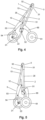
- the extended position which can be seen in Figures 1 , 2 and 3 , the branches (13) of the upper half-frame (1) are aligned with the branches (20) of the second half-frame (2).
- the force exerted by the spring (316) against the locking element (4) causes half of the volume of the locking element (4) to be housed in the first cavity (312) and the other half of the volume of the locking element (4) to be housed in the second cavity (322), preventing the relative rotation between the first body (31) and the second body (32).
- the locking of the relative rotation between the first body (31) and the second body (32) is caused by the insertion of the protuberances (41) in the lateral notches (313) of the first cavity (312) and in the lateral notches (324) of the second cavity (322).
- the button (325) is pressed, the branches (326) of the button (325) push the locking element (4), overcoming the force exerted by the spring, causing the locking element (4) to be completely introduced into the first cavity (312).
- the relative rotation between the first body (31) and the second body (32) is enabled. Once the relative rotation has started between both bodies (31, 32), it is not necessary to keep the button (325) pressed for the rotation to continue taking place.
- the first body (31) forms a first stop (317) on the surface thereof
- the second body (32) forms a second stop (329) on the surface thereof, which prevent the relative rotation between the first body (31) and the second body (32) in the direction opposite from the direction in which the folded position is reached from the extended position.
- the support structure (5) of the bag of the shopping trolley is formed by a base (51) of the bag , a support body (53) and a pair of joining straps (54).
- the base (51) of the bag is formed by a body, preferably a U-shaped bar articulated at the ends thereof to the branches of the lower half-frame, above the perpendicular portions, extending in the unfolded position parallel to said perpendicular portions of the lower half-frame, and when it is in the folded position, it extends parallel to the branches of the lower half-frame.
- the base (51) of the bag is joined to articulation parts (52) which enable the relative rotation of the base (51) of the bag with respect to the lower half-frame (2) towards the folded position, but prevent the relative rotation of the base (51) of the bag with respect to the lower half-frame (2) towards the other direction, since said articulation parts (52) comprise a portion or segment surrounding the branch (20) of the lower half-frame (2) and acts as a stop.
- the support body (53) is U-shaped, and is articulated at the ends thereof to the base (51) of the bag .
- said support body (53) is joined to the ends of the perpendicular portions (21) of the lower half-frame (2) by means of the joining straps (54), articulated at both ends.
- the rear wheels (61) are arranged in a support (60) articulated to the branches of the lower half-frame (2), on the side opposite from the support structure (5) of the bag of the trolley.
- Figure 3 shows the folded shape of the support structure (5) of the bag of the shopping trolley
- Figure 4 shows the folding of the upper half-frame (1) on the lower half-frame (2)
- Figure 5 shows the shopping trolley frame object of the present invention, wherein both the support structure (5) of the bag of the shopping trolley, as well as the upper half-frame (1) and the support (60) for the rear wheels (61) are in the folded position.
- Said Figure 5 shows that when the support (60) for the rear wheels (61) is folded on the lower half-frame (2), the front wheels (22) and the rear wheels (61) form four bearing points on the surface, staying in the centre of gravity of the folded frame at a point perpendicular to the plane defined by said four bearing points, enabling the folded frame to be kept in an upright position.
Landscapes
- Engineering & Computer Science (AREA)
- Chemical & Material Sciences (AREA)
- Combustion & Propulsion (AREA)
- Transportation (AREA)
- Mechanical Engineering (AREA)
- Handcart (AREA)
Claims (8)
- Zusammenklappbares Gestell für einen Einkaufswagen, umfassend einen oberen Halbrahmen (1), einen unteren Halbrahmen (2), einen Gelenkmechanismus (3) zwischen dem oberen Halbrahmen und dem unteren Halbrahmen, eine Stützstruktur (5) für eine Tasche und eine Stütze (60) für die Hinterräder (61), wobei:• der obere Halbrahmen (1) durch eine U-förmige Struktur gebildet ist, die eine Querstange (11) zwischen den beiden Schenkeln (13) des U umfasst, um eine Tasche zu befestigen, und in deren oberen Abschnitt sie einen Handgriff (12) für den Einkaufswagen bildet, wobei die beiden Schenkel (13) des oberen Halbrahmens durch Stangen gebildet sind, an deren jeweiligen Enden sie mit dem unteren Halbrahmen (2) gelenkig verbunden sind;• der untere Halbrahmen (2) durch eine aus Stangen gebildete U-förmige Struktur gebildet ist, wobei am unteren Ende jedes der Schenkel (20) der U-förmigen Struktur ein Vorderrad (22) angeordnet ist;• die Stütze (60) für die Hinterräder an den Schenkeln (20) des unteren Halbrahmens (2) angelenkt ist und auf den unteren Halbrahmen (2) geklappt werden kann;dadurch gekennzeichnet, dass der Gelenkmechanismus (3) durch zwei Körper gebildet ist, einen ersten Körper (31) und einen zweiten Körper (32), wobei jeder der Körper einen im Wesentlichen zylindrischen Hohlraum aufweist, die ein Gehäuse für ein Verriegelungselement (4) definieren, wobei das Verriegelungselement ein zylindrischer Körper ist, der zwei diametral gegenüberliegende Vorsprünge (41) umfasst, wobei:• der erste Körper (31) des Gelenkmechanismus (3) durch einen ersten Halbkörper (310), der einen im Wesentlichen zylindrischen ersten Hohlraum (312) definiert, der ein Paar diametral gegenüberliegender seitlicher Kerben (313) umfasst, die das Verriegelungselement (4) aufnehmen können, wobei die Geometrie des ersten Hohlraums (312) und des Verriegelungselements (4) übereinstimmen, wobei das Verriegelungselement (4) vollständig in den ersten Hohlraum (312) eingeführt werden kann; und einen zweiten Gehäusehalbkörper (311) zum Einführen eines der Schenkel (13) des oberen Halbrahmens (1) gebildet ist; wobei die Welle, die durch das geometrische Zentrum des ersten Hohlraums (312) verläuft, exzentrisch zur Welle des zweiten Halbkörpers (311) und daher zur Welle des Schenkels (13) des oberen Halbrahmens (1) ist, der in den zweiten Halbkörper (311) einführt ist; wobei aus dem geometrischen Zentrum des ersten Hohlraums (312) ein Vorsprung (314) hervortritt, der ein Durchgangsloch umfasst, das in der Lage ist, ein Verbindungselement zwischen dem ersten Körper (31) und dem zweiten Körper (32) aufzunehmen, wobei das Verriegelungselement (4) durch das Loch (42) eingeführt wird; wobei die Unterseite des ersten Hohlraums (312) eine kreisförmige Nut (315) zum Einsetzen einer Feder (316) bildet, wobei die Feder (316) eine Kraft auf das Verriegelungselement (4) ausübt, die dazu neigt, das Verriegelungselement (4) zur Außenseite des ersten Hohlraums (312) hin zu bewegen;• der zweite Körper (32) einen ersten Halbkörper (320) umfasst, der einen im Wesentlichen zylindrischen zweiten Hohlraum (322) definiert, der ein Paar diametral gegenüberliegender seitlicher Kerben (324) umfasst, deren Querschnitt mit dem Querschnitt des Verriegelungselements (4) übereinstimmt, und dessen Tiefe etwa die Hälfte der Höhe des Verriegelungselements (4) beträgt; und einen zweiten Halbkörper (321) umfasst, der ein Gehäuse mit einer gekrümmten Form definiert, das sowohl das erste Segment des Schenkels des "U" des unteren Halbrahmens (2) als auch das erste Segment des Mittelabschnitts des "U" des unteren Halbrahmens (2) aufnimmt; wobei die Welle, die durch das geometrische Zentrum des zweiten Hohlraums (322) verläuft, exzentrisch zur Welle des Schenkels (20) des unteren Halbrahmens (2) ist, wenn der untere Halbrahmen (2) in dem zweiten Halbkörper (321) aufgenommen ist; wobei die Unterseite des Hohlraums (322) des ersten Halbkörpers (320) des zweiten Körpers (32) des Gelenkmechanismus (3) eine Öffnung umfasst, durch die ein Knopf (325) von dem äußeren Abschnitt des zweiten Halbkörpers (320) eingeführt wird, d. h. von der Seite, die der Seite gegenüberliegt, in der der Hohlraum gebildet ist und durch die das Verriegelungselement (4) eingeführt wird; wobei der zweite Hohlraum (322) ferner eine diametrale Brücke (324) umfasst, die das Einführen von zwei Schenkeln (326) des Knopfs (325) ermöglicht, wobei die Schenkel (326) eine Kraft auf das Verriegelungselement (4) ausüben, wenn der Knopf (325) betätigt wird; wobei die diametrale Brücke (324) ein Anschlag des Verriegelungselements (4) in dem zweiten Hohlraum (322) ist; und die diametrale Brücke (324) ein zentrales Loch umfasst, in das das Verbindungselement einführt ist, das das Durchgangsloch des Vorsprungs (314) durchquert und den ersten Körper (31) und den zweiten Körper (32) verbindet.
- Zusammenklappbares Gestell für einen Einkaufswagen nach Anspruch 1, dadurch gekennzeichnet, dass die Schenkel (326) des Knopfes einen Flansch (327) an dessen Ende aufweisen, der elastisch mit einem Gesims (328) gekoppelt ist, das in der Wand des zweiten Hohlraums (322) des ersten Halbkörpers (320) des zweiten Körpers (320) gebildet ist.
- Zusammenklappbares Gestell für einen Einkaufswagen nach einem der Ansprüche 1 bis 2, dadurch gekennzeichnet, dass der erste Körper (31) einen ersten Anschlag (317) auf seiner Oberfläche bildet und der zweite Körper (32) einen zweiten Anschlag (329) auf seiner Oberfläche bildet, wobei die Anschläge die Relativdrehung zwischen dem ersten Körper (31) und dem zweiten Körper (32) in der Richtung entgegengesetzt zu der Richtung, in der die zusammengeklappte Position von der ausgezogenen Position erreicht wird, verhindern.
- Zusammenklappbares Gestell für einen Einkaufswagen nach einem der Ansprüche 1 bis 3, dadurch gekennzeichnet, dass die Stützstruktur (5) der Tasche des Einkaufswagens durch einen Boden (51) der Tasche, einen Stützkörper (53) und ein Paar Verbindungsbänder (54) gebildet ist.
- Zusammenklappbares Gestell für einen Einkaufswagen nach Anspruch 4, dadurch gekennzeichnet, dass der Boden (51) der Tasche durch einen U-förmigen Körper gebildet ist, der an den Schenkeln (20) des unteren Halbrahmens (2) angelenkt ist; der Stützkörper (53) U-förmig ist und an seinen Enden an den Boden (51) der Tasche angelenkt ist; und dass der Stützkörper (53) mit den Schenkeln (20) mittels der Verbindungsbänder (51) verbunden ist, die an beiden Enden gelenkig sind, wobei die Stützstruktur der Tasche ein gelenkiges Trapezoid bildet.
- Zusammenklappbares Gestell für einen Einkaufswagen nach Anspruch 5, dadurch gekennzeichnet, dass der Boden (51) der Tasche mit Gelenkteilen (52) verbunden ist, die die relative Drehung des Bodens (51) der Tasche in Bezug auf den unteren Halbrahmen (2) in eine zusammengeklappte Position ermöglichen, aber die relative Drehung des Bodens (51) der Tasche in Bezug auf den unteren Halbrahmen (2) in die andere Richtung verhindern, wobei die Gelenkteile (52) einen Abschnitt oder ein Segment umfassen, der bzw. das den Schenkel (20) des unteren Halbrahmens (2) umgibt, der bzw. die als Anschlag dient.
- Zusammenklappbares Gestell für einen Einkaufswagen nach einem der vorhergehenden Ansprüche, dadurch gekennzeichnet, dass die Abschnitte (21) der Enden der Schenkel (20) des unteren Halbrahmens (2) eine Anordnung senkrecht zu den Schenkeln (20) selbst aufweisen, wobei die Verbindung zwischen den senkrechten Abschnitten (21) und jedem der Schenkel (20) des "U" eine Kurve bildet, und wobei die Vorderräder (22) auf einer Welle angeordnet sind, die mit beiden Enden der senkrechten Abschnitte (21) verbunden ist.
- Zusammenklappbares Gestell für einen Einkaufswagen nach einem der vorhergehenden Ansprüche, dadurch gekennzeichnet, dass, wenn die Stütze (60) für die Hinterräder (61) auf den unteren Halbrahmen (2) geklappt ist, die Vorderräder (22) und die Hinterräder (61) vier Lagerpunkte auf der Oberfläche bilden, wobei sie in der Mitte der Schwerkraft des zusammengeklappten Gestells an einem Punkt senkrecht zu der Ebene, die durch die vier Lagerpunkte definiert ist, bleiben, wodurch das zusammengeklappte Gestell in einer aufrechten Position gehalten werden kann.
Applications Claiming Priority (1)
| Application Number | Priority Date | Filing Date | Title |
|---|---|---|---|
| ES201930539U ES1231310Y (es) | 2019-04-03 | 2019-04-03 | Bastidor plegable para carro de compra |
Publications (2)
| Publication Number | Publication Date |
|---|---|
| EP3733477A1 EP3733477A1 (de) | 2020-11-04 |
| EP3733477B1 true EP3733477B1 (de) | 2023-07-19 |
Family
ID=66822267
Family Applications (1)
| Application Number | Title | Priority Date | Filing Date |
|---|---|---|---|
| EP20177443.7A Active EP3733477B1 (de) | 2019-04-03 | 2020-05-29 | Faltbarer rahmen für einen einkaufswagen |
Country Status (4)
| Country | Link |
|---|---|
| EP (1) | EP3733477B1 (de) |
| ES (1) | ES1231310Y (de) |
| RU (1) | RU200713U1 (de) |
| UA (1) | UA145782U (de) |
Family Cites Families (13)
| Publication number | Priority date | Publication date | Assignee | Title |
|---|---|---|---|---|
| US5348325A (en) * | 1991-10-11 | 1994-09-20 | Martin Abrams | Portable, collapsible luggage carrier |
| ES1019403Y (es) | 1991-11-26 | 1993-04-16 | Garcia Moll Jaime | Bastidor para carros de compra y similares. |
| ES1023908Y (es) | 1993-02-18 | 1994-11-16 | Moll Jaime Garcia | Bastidor rodante para carros de compra. |
| RU2097243C1 (ru) * | 1994-03-28 | 1997-11-27 | Ангелина Васильевна Сопина | Ручная одноосная складная тележка |
| ES1041293Y (es) | 1998-07-29 | 2000-01-01 | Bellod S L | Base de soporte perfeccionada aplicable en carros de compras y similares. |
| ES1044006Y (es) | 1999-09-14 | 2001-03-01 | Germans Server Sl | Carro de compra. |
| ES1047678Y (es) * | 2000-11-22 | 2001-09-16 | Moll Jaime Garcia | Carrito de compra. |
| ES1051638Y (es) | 2002-04-01 | 2003-01-16 | Moll Jaime Garcia | Dispositivo para plegado de bastidores de carros de compra. |
| ES1055557Y (es) | 2003-09-15 | 2004-04-16 | Germans Server Sl | Bolsa para carro de compra. |
| ES1058599Y (es) * | 2004-09-22 | 2005-04-16 | Germans Server Sl | Carro de compra. |
| ES1066018Y (es) * | 2007-08-09 | 2008-06-16 | Moll Jaime Garcia | Carrito de compra |
| ES1070351Y (es) | 2009-04-15 | 2010-02-25 | Moll Jaime Garcia | Carrito de compra |
| CN204641808U (zh) * | 2015-03-18 | 2015-09-16 | 奇立科技有限公司 | 购物车 |
-
2019
- 2019-04-03 ES ES201930539U patent/ES1231310Y/es active Active
-
2020
- 2020-05-28 RU RU2020117647U patent/RU200713U1/ru active
- 2020-05-28 UA UAU202003241U patent/UA145782U/uk unknown
- 2020-05-29 EP EP20177443.7A patent/EP3733477B1/de active Active
Also Published As
| Publication number | Publication date |
|---|---|
| ES1231310Y (es) | 2019-09-10 |
| UA145782U (uk) | 2021-01-06 |
| RU200713U1 (ru) | 2020-11-06 |
| ES1231310U (es) | 2019-06-20 |
| EP3733477A1 (de) | 2020-11-04 |
Similar Documents
| Publication | Publication Date | Title |
|---|---|---|
| US11370469B2 (en) | Collapsible stroller | |
| EP2248707B1 (de) | Kinderwagen | |
| US8696015B2 (en) | Stroller | |
| JP6829933B2 (ja) | ベビーカーフレーム及びベビーカー | |
| EP1671869B1 (de) | Klappbarer Rahmen für Kinderwagen | |
| EP2765072B1 (de) | Zusammenklappbarer Rahmen für ein Fahrrad | |
| EP1741614B1 (de) | Klappbarer Rahmen für Kinderwagen | |
| NL2011101C2 (en) | Stroller. | |
| EP1466810B1 (de) | Schiebewagen | |
| JP2006514903A (ja) | 折りたためる構造体システム | |
| JP2015058930A (ja) | ベビーカー用シャーシ | |
| CN107985378B (zh) | 儿童推车 | |
| CN106364541B (zh) | 一种可折叠车架 | |
| EP2781430A1 (de) | Zusammenklappbarer Kinderbuggy | |
| CN109789887B (zh) | 童车 | |
| CN207737353U (zh) | 一种推车骨架以及儿童推车 | |
| EP3733477B1 (de) | Faltbarer rahmen für einen einkaufswagen | |
| CN107140002B (zh) | 一种儿童推车 | |
| CN107776641B (zh) | 推车车架 | |
| CN106741087B (zh) | 折叠车架及儿童拖车 | |
| CN205440490U (zh) | 一种可折叠婴儿推车 | |
| CN212332757U (zh) | 收折站立的儿童推车 | |
| EP0900709A2 (de) | Kinderwagen | |
| CN210310429U (zh) | 一种车轮可收折的手推车 | |
| TWI805154B (zh) | 車架鎖定機構及具有該車架鎖定機構的手推車 |
Legal Events
| Date | Code | Title | Description |
|---|---|---|---|
| PUAI | Public reference made under article 153(3) epc to a published international application that has entered the european phase |
Free format text: ORIGINAL CODE: 0009012 |
|
| STAA | Information on the status of an ep patent application or granted ep patent |
Free format text: STATUS: THE APPLICATION HAS BEEN PUBLISHED |
|
| AK | Designated contracting states |
Kind code of ref document: A1 Designated state(s): AL AT BE BG CH CY CZ DE DK EE ES FI FR GB GR HR HU IE IS IT LI LT LU LV MC MK MT NL NO PL PT RO RS SE SI SK SM TR |
|
| AX | Request for extension of the european patent |
Extension state: BA ME |
|
| STAA | Information on the status of an ep patent application or granted ep patent |
Free format text: STATUS: REQUEST FOR EXAMINATION WAS MADE |
|
| 17P | Request for examination filed |
Effective date: 20210503 |
|
| RBV | Designated contracting states (corrected) |
Designated state(s): AL AT BE BG CH CY CZ DE DK EE ES FI FR GB GR HR HU IE IS IT LI LT LU LV MC MK MT NL NO PL PT RO RS SE SI SK SM TR |
|
| STAA | Information on the status of an ep patent application or granted ep patent |
Free format text: STATUS: EXAMINATION IS IN PROGRESS |
|
| 17Q | First examination report despatched |
Effective date: 20220222 |
|
| GRAP | Despatch of communication of intention to grant a patent |
Free format text: ORIGINAL CODE: EPIDOSNIGR1 |
|
| STAA | Information on the status of an ep patent application or granted ep patent |
Free format text: STATUS: GRANT OF PATENT IS INTENDED |
|
| INTG | Intention to grant announced |
Effective date: 20230208 |
|
| GRAS | Grant fee paid |
Free format text: ORIGINAL CODE: EPIDOSNIGR3 |
|
| GRAA | (expected) grant |
Free format text: ORIGINAL CODE: 0009210 |
|
| STAA | Information on the status of an ep patent application or granted ep patent |
Free format text: STATUS: THE PATENT HAS BEEN GRANTED |
|
| AK | Designated contracting states |
Kind code of ref document: B1 Designated state(s): AL AT BE BG CH CY CZ DE DK EE ES FI FR GB GR HR HU IE IS IT LI LT LU LV MC MK MT NL NO PL PT RO RS SE SI SK SM TR |
|
| REG | Reference to a national code |
Ref country code: GB Ref legal event code: FG4D |
|
| REG | Reference to a national code |
Ref country code: CH Ref legal event code: EP |
|
| REG | Reference to a national code |
Ref country code: DE Ref legal event code: R096 Ref document number: 602020013949 Country of ref document: DE |
|
| REG | Reference to a national code |
Ref country code: IE Ref legal event code: FG4D |
|
| REG | Reference to a national code |
Ref country code: LT Ref legal event code: MG9D |
|
| REG | Reference to a national code |
Ref country code: NL Ref legal event code: MP Effective date: 20230719 |
|
| REG | Reference to a national code |
Ref country code: AT Ref legal event code: MK05 Ref document number: 1589198 Country of ref document: AT Kind code of ref document: T Effective date: 20230719 |
|
| PG25 | Lapsed in a contracting state [announced via postgrant information from national office to epo] |
Ref country code: NL Free format text: LAPSE BECAUSE OF FAILURE TO SUBMIT A TRANSLATION OF THE DESCRIPTION OR TO PAY THE FEE WITHIN THE PRESCRIBED TIME-LIMIT Effective date: 20230719 |
|
| PG25 | Lapsed in a contracting state [announced via postgrant information from national office to epo] |
Ref country code: IS Free format text: LAPSE BECAUSE OF FAILURE TO SUBMIT A TRANSLATION OF THE DESCRIPTION OR TO PAY THE FEE WITHIN THE PRESCRIBED TIME-LIMIT Effective date: 20231119 |
|
| PG25 | Lapsed in a contracting state [announced via postgrant information from national office to epo] |
Ref country code: SE Free format text: LAPSE BECAUSE OF FAILURE TO SUBMIT A TRANSLATION OF THE DESCRIPTION OR TO PAY THE FEE WITHIN THE PRESCRIBED TIME-LIMIT Effective date: 20230719 Ref country code: RS Free format text: LAPSE BECAUSE OF FAILURE TO SUBMIT A TRANSLATION OF THE DESCRIPTION OR TO PAY THE FEE WITHIN THE PRESCRIBED TIME-LIMIT Effective date: 20230719 Ref country code: PT Free format text: LAPSE BECAUSE OF FAILURE TO SUBMIT A TRANSLATION OF THE DESCRIPTION OR TO PAY THE FEE WITHIN THE PRESCRIBED TIME-LIMIT Effective date: 20231120 Ref country code: NO Free format text: LAPSE BECAUSE OF FAILURE TO SUBMIT A TRANSLATION OF THE DESCRIPTION OR TO PAY THE FEE WITHIN THE PRESCRIBED TIME-LIMIT Effective date: 20231019 Ref country code: LV Free format text: LAPSE BECAUSE OF FAILURE TO SUBMIT A TRANSLATION OF THE DESCRIPTION OR TO PAY THE FEE WITHIN THE PRESCRIBED TIME-LIMIT Effective date: 20230719 Ref country code: LT Free format text: LAPSE BECAUSE OF FAILURE TO SUBMIT A TRANSLATION OF THE DESCRIPTION OR TO PAY THE FEE WITHIN THE PRESCRIBED TIME-LIMIT Effective date: 20230719 Ref country code: IS Free format text: LAPSE BECAUSE OF FAILURE TO SUBMIT A TRANSLATION OF THE DESCRIPTION OR TO PAY THE FEE WITHIN THE PRESCRIBED TIME-LIMIT Effective date: 20231119 Ref country code: HR Free format text: LAPSE BECAUSE OF FAILURE TO SUBMIT A TRANSLATION OF THE DESCRIPTION OR TO PAY THE FEE WITHIN THE PRESCRIBED TIME-LIMIT Effective date: 20230719 Ref country code: FI Free format text: LAPSE BECAUSE OF FAILURE TO SUBMIT A TRANSLATION OF THE DESCRIPTION OR TO PAY THE FEE WITHIN THE PRESCRIBED TIME-LIMIT Effective date: 20230719 Ref country code: AT Free format text: LAPSE BECAUSE OF FAILURE TO SUBMIT A TRANSLATION OF THE DESCRIPTION OR TO PAY THE FEE WITHIN THE PRESCRIBED TIME-LIMIT Effective date: 20230719 |
|
| PG25 | Lapsed in a contracting state [announced via postgrant information from national office to epo] |
Ref country code: PL Free format text: LAPSE BECAUSE OF FAILURE TO SUBMIT A TRANSLATION OF THE DESCRIPTION OR TO PAY THE FEE WITHIN THE PRESCRIBED TIME-LIMIT Effective date: 20230719 |
|
| REG | Reference to a national code |
Ref country code: DE Ref legal event code: R097 Ref document number: 602020013949 Country of ref document: DE |
|
| PG25 | Lapsed in a contracting state [announced via postgrant information from national office to epo] |
Ref country code: ES Free format text: LAPSE BECAUSE OF FAILURE TO SUBMIT A TRANSLATION OF THE DESCRIPTION OR TO PAY THE FEE WITHIN THE PRESCRIBED TIME-LIMIT Effective date: 20230719 |
|
| PG25 | Lapsed in a contracting state [announced via postgrant information from national office to epo] |
Ref country code: SM Free format text: LAPSE BECAUSE OF FAILURE TO SUBMIT A TRANSLATION OF THE DESCRIPTION OR TO PAY THE FEE WITHIN THE PRESCRIBED TIME-LIMIT Effective date: 20230719 Ref country code: RO Free format text: LAPSE BECAUSE OF FAILURE TO SUBMIT A TRANSLATION OF THE DESCRIPTION OR TO PAY THE FEE WITHIN THE PRESCRIBED TIME-LIMIT Effective date: 20230719 Ref country code: ES Free format text: LAPSE BECAUSE OF FAILURE TO SUBMIT A TRANSLATION OF THE DESCRIPTION OR TO PAY THE FEE WITHIN THE PRESCRIBED TIME-LIMIT Effective date: 20230719 Ref country code: EE Free format text: LAPSE BECAUSE OF FAILURE TO SUBMIT A TRANSLATION OF THE DESCRIPTION OR TO PAY THE FEE WITHIN THE PRESCRIBED TIME-LIMIT Effective date: 20230719 Ref country code: DK Free format text: LAPSE BECAUSE OF FAILURE TO SUBMIT A TRANSLATION OF THE DESCRIPTION OR TO PAY THE FEE WITHIN THE PRESCRIBED TIME-LIMIT Effective date: 20230719 Ref country code: CZ Free format text: LAPSE BECAUSE OF FAILURE TO SUBMIT A TRANSLATION OF THE DESCRIPTION OR TO PAY THE FEE WITHIN THE PRESCRIBED TIME-LIMIT Effective date: 20230719 Ref country code: SK Free format text: LAPSE BECAUSE OF FAILURE TO SUBMIT A TRANSLATION OF THE DESCRIPTION OR TO PAY THE FEE WITHIN THE PRESCRIBED TIME-LIMIT Effective date: 20230719 |
|
| PLBE | No opposition filed within time limit |
Free format text: ORIGINAL CODE: 0009261 |
|
| STAA | Information on the status of an ep patent application or granted ep patent |
Free format text: STATUS: NO OPPOSITION FILED WITHIN TIME LIMIT |
|
| PG25 | Lapsed in a contracting state [announced via postgrant information from national office to epo] |
Ref country code: IT Free format text: LAPSE BECAUSE OF FAILURE TO SUBMIT A TRANSLATION OF THE DESCRIPTION OR TO PAY THE FEE WITHIN THE PRESCRIBED TIME-LIMIT Effective date: 20230719 |
|
| 26N | No opposition filed |
Effective date: 20240422 |
|
| PGFP | Annual fee paid to national office [announced via postgrant information from national office to epo] |
Ref country code: DE Payment date: 20240521 Year of fee payment: 5 |
|
| PG25 | Lapsed in a contracting state [announced via postgrant information from national office to epo] |
Ref country code: SI Free format text: LAPSE BECAUSE OF FAILURE TO SUBMIT A TRANSLATION OF THE DESCRIPTION OR TO PAY THE FEE WITHIN THE PRESCRIBED TIME-LIMIT Effective date: 20230719 |
|
| PGFP | Annual fee paid to national office [announced via postgrant information from national office to epo] |
Ref country code: FR Payment date: 20240522 Year of fee payment: 5 |