EP3733050B1 - Bildverarbeitungsverfahren, bildverarbeitungsprogramm, bildverarbeitungsvorrichtung, bildanzeigevorrichtung und bildanzeigeverfahren - Google Patents
Bildverarbeitungsverfahren, bildverarbeitungsprogramm, bildverarbeitungsvorrichtung, bildanzeigevorrichtung und bildanzeigeverfahren Download PDFInfo
- Publication number
- EP3733050B1 EP3733050B1 EP17936466.6A EP17936466A EP3733050B1 EP 3733050 B1 EP3733050 B1 EP 3733050B1 EP 17936466 A EP17936466 A EP 17936466A EP 3733050 B1 EP3733050 B1 EP 3733050B1
- Authority
- EP
- European Patent Office
- Prior art keywords
- image
- image processing
- fundus
- non perfusion
- perfusion area
- Prior art date
- Legal status (The legal status is an assumption and is not a legal conclusion. Google has not performed a legal analysis and makes no representation as to the accuracy of the status listed.)
- Active
Links
Images







Classifications
-
- A—HUMAN NECESSITIES
- A61—MEDICAL OR VETERINARY SCIENCE; HYGIENE
- A61B—DIAGNOSIS; SURGERY; IDENTIFICATION
- A61B3/00—Apparatus for testing the eyes; Instruments for examining the eyes
- A61B3/0016—Operational features thereof
- A61B3/0025—Operational features thereof characterised by electronic signal processing, e.g. eye models
-
- A—HUMAN NECESSITIES
- A61—MEDICAL OR VETERINARY SCIENCE; HYGIENE
- A61B—DIAGNOSIS; SURGERY; IDENTIFICATION
- A61B3/00—Apparatus for testing the eyes; Instruments for examining the eyes
- A61B3/0016—Operational features thereof
- A61B3/0041—Operational features thereof characterised by display arrangements
-
- A—HUMAN NECESSITIES
- A61—MEDICAL OR VETERINARY SCIENCE; HYGIENE
- A61B—DIAGNOSIS; SURGERY; IDENTIFICATION
- A61B3/00—Apparatus for testing the eyes; Instruments for examining the eyes
- A61B3/10—Objective types, i.e. instruments for examining the eyes independent of the patients' perceptions or reactions
- A61B3/102—Objective types, i.e. instruments for examining the eyes independent of the patients' perceptions or reactions for optical coherence tomography [OCT]
-
- A—HUMAN NECESSITIES
- A61—MEDICAL OR VETERINARY SCIENCE; HYGIENE
- A61B—DIAGNOSIS; SURGERY; IDENTIFICATION
- A61B3/00—Apparatus for testing the eyes; Instruments for examining the eyes
- A61B3/10—Objective types, i.e. instruments for examining the eyes independent of the patients' perceptions or reactions
- A61B3/12—Objective types, i.e. instruments for examining the eyes independent of the patients' perceptions or reactions for looking at the eye fundus, e.g. ophthalmoscopes
- A61B3/1225—Objective types, i.e. instruments for examining the eyes independent of the patients' perceptions or reactions for looking at the eye fundus, e.g. ophthalmoscopes using coherent radiation
- A61B3/1233—Objective types, i.e. instruments for examining the eyes independent of the patients' perceptions or reactions for looking at the eye fundus, e.g. ophthalmoscopes using coherent radiation for measuring blood flow, e.g. at the retina
-
- A—HUMAN NECESSITIES
- A61—MEDICAL OR VETERINARY SCIENCE; HYGIENE
- A61B—DIAGNOSIS; SURGERY; IDENTIFICATION
- A61B3/00—Apparatus for testing the eyes; Instruments for examining the eyes
- A61B3/10—Objective types, i.e. instruments for examining the eyes independent of the patients' perceptions or reactions
- A61B3/14—Arrangements specially adapted for eye photography
-
- G—PHYSICS
- G06—COMPUTING OR CALCULATING; COUNTING
- G06T—IMAGE DATA PROCESSING OR GENERATION, IN GENERAL
- G06T7/00—Image analysis
- G06T7/0002—Inspection of images, e.g. flaw detection
-
- G—PHYSICS
- G06—COMPUTING OR CALCULATING; COUNTING
- G06T—IMAGE DATA PROCESSING OR GENERATION, IN GENERAL
- G06T7/00—Image analysis
- G06T7/0002—Inspection of images, e.g. flaw detection
- G06T7/0012—Biomedical image inspection
-
- G—PHYSICS
- G06—COMPUTING OR CALCULATING; COUNTING
- G06T—IMAGE DATA PROCESSING OR GENERATION, IN GENERAL
- G06T7/00—Image analysis
- G06T7/60—Analysis of geometric attributes
- G06T7/62—Analysis of geometric attributes of area, perimeter, diameter or volume
-
- G—PHYSICS
- G06—COMPUTING OR CALCULATING; COUNTING
- G06T—IMAGE DATA PROCESSING OR GENERATION, IN GENERAL
- G06T2207/00—Indexing scheme for image analysis or image enhancement
- G06T2207/10—Image acquisition modality
- G06T2207/10072—Tomographic images
- G06T2207/10101—Optical tomography; Optical coherence tomography [OCT]
-
- G—PHYSICS
- G06—COMPUTING OR CALCULATING; COUNTING
- G06T—IMAGE DATA PROCESSING OR GENERATION, IN GENERAL
- G06T2207/00—Indexing scheme for image analysis or image enhancement
- G06T2207/30—Subject of image; Context of image processing
- G06T2207/30004—Biomedical image processing
- G06T2207/30041—Eye; Retina; Ophthalmic
Definitions
- the present invention relates to an image processing method, an image processing program, an image processing device, an image display device, and an image display method.
- Patent Document 1 discloses technology for detecting retinal vascular infraction in a test subject.
- an image processing device as recited in claim 10 below.
- SLO scanning laser ophthalmoscope
- OCT optical coherence tomography
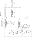
- the ophthalmic system 100 includes an ophthalmic device 110, a field of view measurement instrument 120, a laser photocoagulator 130, a management server device (hereafter referred to as “management server”) 140, and an image display device (hereafter referred to as "image viewer”) 150.
- management server a management server device
- image viewer an image display device
- the ophthalmic device 110 acquires fundus images and tomographic images.
- the field of view measurement instrument 120 measures the field of view of a patient.
- the laser photocoagulator 130 uses a laser to coagulate pathological lesions on a fundus of the patient in order to suppress pathological progression.
- the management server 140 stores plural fundus images, obtained by imaging the fundus of plural patients using the ophthalmic device 110, in association with IDs of the patients, and predicts any non perfusion areas (NPAs) in a specified fundus image.
- the image viewer 150 displays an image of non perfusion area (NPA) candidates predicted by the management server 140.
- NPAs non perfusion areas
- AVAs avascular areas
- the ophthalmic device 110, the field of view measurement instrument 120, the laser photocoagulator 130, the management server 140, and the image viewer 150 are all interconnected over a network 160.
- the horizontal direction is referred to as the "X direction”
- a direction perpendicular to the horizontal direction is referred to as the "Y direction”
- a direction connecting a pupil center 27 at the anterior segment of a subject eye 12 and an eyeball center O of the subject eye 12 is referred to as the "Z direction”.
- the X direction, Y direction, and Z direction are mutually perpendicular directions.
- the SLO imaging system function is implemented by the control device 16, the SLO unit 18, and the wide angled optical system 19 in the configuration of the ophthalmic device 110.
- the SLO unit 18 includes a light source 18A, a detection element 18B, a dichroic mirror 18C and the like, and is configured to perform imaging of the fundus of the subject eye 12 Namely, the fundus (for example an imageable region 12A) of the subject eye 12 is imaged as an imaging subject by operating the ophthalmic device 110 in the SLO imaging system function.
- a common optical system 28 includes, in addition to the third optical scanner 29, a slit mirror 30 and an elliptical mirror 32. Note that side view end faces are illustrated of a dichroic mirror 26, the slit mirror 30, and the elliptical mirror 32. Note that a configuration may also be adopted in which plural lens groups are employed instead of the common optical system 28, the slit mirror 30, and the elliptical mirror 32.
- the slit mirror 30, the elliptical mirror 32, and the third optical scanner 29 are arranged so that the first focal point P3 and the second focal point P2 lie at a common position on the third optical scanner 29. Moreover, the slit mirror 30, the elliptical mirror 32, and the third optical scanner 29 are arranged so that the second focal point P4 is positioned at a central portion of the pupil of the subject eye 12. Furthermore, the first optical scanner 22, the second optical scanner 24, and the slit mirror 30 arranged so that the first focal point P1 is positioned on the first optical scanner 22 and the second optical scanner 24.
- the wide angled optical system 19 as well as being a wide angled optical system employing an elliptical mirror, may also be a wide angled optical system combining an optical system employing a wide angled lens in combination with plural lenses.
- the external illumination angle is an illumination angle of light from the ophthalmic device 110 side, namely from the exterior of the subject eye 12.
- the external illumination angle is the angle of scanned light onto the fundus of the subject eye 12 heading toward a pupil center 27 of the subject eye 12 (namely, a center point of the pupil as viewed face-on (see also Fig. 2 )).
- the external illumination angle is equivalent to the angle of light reflected from the fundus so as to head out from the pupil center 27 and be emitted from the subject eye 12 toward the ophthalmic device 110.
- the ophthalmic device 110 images within the imageable region 12A (see Fig. 2 ), which is a fundus region of the subject eye 12.
- the imageable region 12A is the maximum scannable region with the scanning light using the wide angled optical system 19, and the external illumination angle A is approximately 160 degrees (corresponding to an internal illumination angle of approximately 200 degrees).
- the SLO image obtained by imaging the imageable region 12A is referred to as an UWFSLO image.
- UWF is an abbreviation for Ultra Widefield.
- the configuration of the electrical system of the management server 140 is, similarly to the configuration of the electrical system of the image viewer 150, equipped with a computer main unit 152, including the CPU 162, the RAM 166, the ROM 164, and the input/output (I/O) port 168, and with the storage device 154, the display 156, the mouse 155M, and the keyboard 155K that are connected to the input/output (I/O) port 168.
- a computer main unit 152 including the CPU 162, the RAM 166, the ROM 164, and the input/output (I/O) port 168, and with the storage device 154, the display 156, the mouse 155M, and the keyboard 155K that are connected to the input/output (I/O) port 168.
- the CPU 162 of the management server 140 is an example of an "image processing device" of the technology disclosed herein.
- Fundus image data for test subjects and an image processing program 154P are stored in the storage device 154 of the management server 140.
- the image processing program 154P is stored in the storage device 154, the technology disclosed herein is not limited thereto, and the image processing program 154P may be stored on the ROM 164.
- the image processing program 154P is an example of an image processing program according to technology disclosed herein.
- Elements corresponding to the display 156, the mouse 155M, and the keyboard 155K of the image viewer 150 may be omitted for a configuration of the electrical system of the management server 140.
- the image processing program 154P is equipped with a reception function, an acquisition function, an enhancement image processing function, a prediction processing function, a generation function, and a transmission function.
- the CPU 162 functions as a reception section 200, an acquisition section 202, an enhancement image processing section 204, a prediction processing section 206, a generation section 208, and a transmission section 210 as illustrated in Fig. 5 by the CPU 162 executing the multi-function image processing program 154P.
- the enhancement image processing section 204, the prediction processing section 206, and the generation section 208 may be configured by an integrated image processing chip (an IC, a hardware configuration such as circuit, or the like).
- the ophthalmic system 100 collects basic information about the subject eye 12 of a patient in order to perform a diagnosis on the subject eye 12 of the patient (see Fig. 2 ). More specifically, the eye axial length etc. is measured using a non-illustrated eye axial length measurement instrument, or the like. Furthermore, on instruction by a doctor, the patient goes to a room where the field of view measurement instrument 120 is installed. The field of view measurement instrument 120 measures a visible range (field of view map) by looking at responses of the patient when a light stimulus is imparted to the retina. The field of view measurement instrument 120 transmits the measured field of view map to the management server 140 together with the patient ID. The management server 140 stores the field of view map in the storage device 154 (see Fig.
- the patient On instruction by the doctor, the patient then goes to a room where the ophthalmic device 110 is installed.
- the ophthalmic device 110 images the subject eye 12 of the patient to acquire the fundus image (SLO image (UWFSLO fundus image) and OCT image).
- the ophthalmic device 110 transmits the acquired fundus image to the management server 140 together with the patient ID.
- the management server 140 stores the fundus image in the storage device 154 associated with the patient ID.
- the doctor When examining the subject eye 12 of the patient, the doctor employs the fundus image of the subject eye 12, and sometimes employs information about whether or not there is a non perfusion area on the fundus.
- the patient ID is input to the image viewer 150, then the image viewer 150 acquires the fundus image of the patient from the management server 140, and the acquired fundus image is displayed on the display 156.
- An instruction to generate a perfusion area candidate image for the fundus image being displayed is then transmitted from the image viewer 150 to the management server 140.
- the management server 140 transmits image data for the generated non perfusion area candidate image based on the specified fundus image to the image viewer 150.
- the non perfusion area candidate image is a fundus image with any predicted non perfusion areas displayed so as to be superimposed thereon.
- the management server 140 reads the specified fundus image from the storage device 154, predicts any non perfusion areas in the read fundus image, and generates a final image of candidate areas for non perfusion areas (either as a non perfusion area candidate image or a candidate group image), and transmits the image data for the generated final image to the image viewer 150.
- the image viewer 150 receives the image data for the non perfusion area candidate image using the communication interface I/F 158, and displays the non perfusion area candidate image on the display 156.
- the fundus image is an UWFSLO fundus image imaged with the ophthalmic device 110, and enables the prediction of whether or not there are any NPAs, serving as targets, present across a wide range of the fundus.
- the NPAs may be predicted using fundus images of the same patient (previously imaged UWFSLO fundus images, fundus images imaged with another instrument, or the like).
- the doctor diagnoses the subject eye 12 of the patient based on the non perfusion area candidate image displayed on the display 156. If there is no problem with the subject eye 12 then the consultation is ended. However, in cases in which there is a problem with the subject eye 12 and the doctor has diagnosed a need for an OCT image, then a tomographic image of a fundus layer needs to be acquired using the ophthalmic device 110, and so an instruction to perform imaging by OCT may be output through the image viewer 150 to the ophthalmic device 110.
- the ophthalmic device 110 When instructed to perform imaging by OCT, the ophthalmic device 110 transmits an OCT image acquired with the ophthalmic device 110 to the management server 140 together with the patient ID.
- the management server 140 stores the OCT image in the storage device 154 associated with the patient ID, and also transmits the OCT image to the image viewer 150.
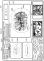
- the image viewer 150 performs screen display in various display modes on the screen 500 of the display 156 of the image viewer 150, as illustrated in Fig. 18 .
- FIG. 6 description follows regarding the image processing program executed by the CPU 162 of the management server 140, with reference to Fig. 6 .
- the image processing illustrated in Fig. 6 is implemented by the CPU 162 of the management server 140 executing the image processing program 154P.
- the image processing illustrated in Fig. 6 is an example of an "image processing method" of technology disclosed herein.
- the image processing program 154P is started when the reception section 200 (see also Fig. 5 ) has received command data from the image viewer 150.
- the command data is issued from the image viewer 150, and relates to a command to generate a non perfusion area (NPA) candidate image from the specified UWFSLO image, and to transmit image data for the non perfusion area (NPA) candidate image to the image viewer 150.
- NPA non perfusion area
- the acquisition section 202 acquires the specified UWFSLO image from out of the plural UWFSLO images stored in the storage device 154 in association with the plural respective patient IDs.
- the UWFSLO images include structures such as retina vascular structures, the optic nerve head, and the like.
- the enhancement image processing section 204 performs enhancement image processing on the acquired UWFSLO image to enhance vascular portions thereof. This processing is processing performed to make the blood vessels including capillary blood vessels more prominent in order to predict non perfusion areas (NPAs) with good precision.
- NPAs non perfusion areas
- the enhancement image processing may employ various methods, such as enhancement processing in which an image histogram is employed, as in histogram averaging and contrast limited adaptive histogram equalization (CLAHE), or alternatively such as contrast conversion processing based on gradation conversion, frequency enhancement processing for a particular frequency band such as processing by unsharp masking, deconvolution processing such processing by Weiner filter, morphology processing to enhance the shape of vascular portions, or the like.
- CLAHE contrast limited adaptive histogram equalization
- contrast conversion processing based on gradation conversion
- frequency enhancement processing for a particular frequency band such as processing by unsharp masking
- deconvolution processing such processing by Weiner filter
- morphology processing to enhance the shape of vascular portions, or the like.
- histogram averaging or adaptive histogram equalization is employed therefor.
- the blood vessels are enhanced by the enhancement image processing, and the capillary blood vessels are also enhanced as illustrated in Fig. 8 .
- the prediction processing section 206 predicts plural non perfusion areas (NPAs) in the UWFSLO image in which the blood vessels have been enhanced.
- pixel values for example, brightness values expressing lightness may be employed therefor, however, values expressing at least one out of saturation or hue may also be employed therefor instead of brightness values, or as well as the brightness values.
- a primary candidate is an example of a "first non perfusion area candidate" of the technology disclosed herein.
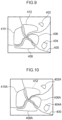
- the prediction processing section 206 narrows down the plural primary candidates for non perfusion areas (NPAs) to only areas having blood vessels running alongside. More specifically, first the prediction processing section 206 (1) extracts blood vessels. The blood vessels are extracted based on the pixel values using a method such as morphology processing or binarization or the like. Note that the areas extracted thereby are referred to as vascular areas. Then the prediction processing section 206 (2) uses a method such as distance conversion to compute a distance between such vascular areas and the peripheral edges of a single or plural primary candidates for non perfusion areas (NPAs) or for, or of each area group of candidate groups for non perfusion areas (NPAs), and selects areas in which this computed distance is within a fixed range.
- NPAs non perfusion areas
- the prediction processing section 206 extracts from the primary candidates areas for which a distance to blood vessels is a first distance or lower, as second secondary candidates areas.
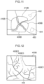
- the candidates 402, 404 are, for example, accordingly excluded as they are not areas having blood vessels running alongside, as illustrated in Fig. 11 . This thereby narrows down the candidates to the second secondary candidates 406B, 408B, 410B, 412B as candidates having blood vessels running alongside.
- the generation section 208 applies a colored border to the periphery of the predicted non perfusion areas in the UWFSLO image to generate the non perfusion area candidate image.
- the non perfusion area candidate image refers to a fundus image in which predicted non perfusion areas are displayed superimposed on the UWFSLO image so as to enable positions of the predicted non perfusion areas on the UWFSLO image to be easily ascertained.
- the predicted non perfusion areas are displayed surrounded by borders in the image in order to enable the positions of the predicted non perfusion areas on the UWFSLO image to be easily ascertained.
- part of the UWFSLO image is, as illustrated in Fig. 15 , displayed with colored borders applied to the peripheries of the predicted non perfusion areas 406NPA, 408NPA, 410NPA.
- the non perfusion area candidate image may be generated by the generation section 208 applying light color shading (a color of a first density darker than the density of the UWFSLO image) to the predicted non perfusion areas 406NPA, 408NPA, 410NPA, as illustrated in Fig. 16 .
- the generation section 208 may shade the predicted non perfusion areas 406NPA, 408NPA, 410NPA with a similar color to real color, or a different color to real color, as illustrated in Fig. 17 .
- broken lines may be employed for the borders at the periphery of the predicted non perfusion areas 406NPA, 408NPA, 410NPA.
- the non perfusion area candidate image is an example of information employed by a doctor to diagnose or determine the progress of diabetic retinopathy, retinal vein occlusion, or the like.
- the transmission section 210 transmits the image data for the non perfusion area candidate image generated at step 314 to the image viewer 150.
- the image viewer 150 On receipt of data for the non perfusion area candidate image, the image viewer 150 displays the non perfusion area candidate image on the display 156.
- the display methods illustrated in Fig. 18 and Fig. 19 are examples of an "image display method" of technology disclosed herein.
- Fig. 18 illustrates a display content of an NPA analysis mode of the display 156 of the image viewer 150 displayed on the screen 500.
- the screen 500 includes a patient information display field 502, a UWFSLO image display field 504, an OCT image display field 506, a non perfusion area candidate image display field 508, and two enlarged image display fields 510, 512.
- the screen 500 also includes a menu button 522, an NPA tracking observation button 524, an NPA analysis button 526, an NPA laser coagulation button 528, an NPA field of view analysis button 530, and an OCT analysis button 540.
- the screen 500 also includes a tool button display field 540.
- Fig. 18 illustrates a display screen for an NPA analysis mode and so, from out of the menu button 522, the NPA tracking observation button 524, the NPA analysis button 526, the NPA laser coagulation button 528, the NPA field of view analysis button 530, and the OCT analysis button 540, the NPA analysis button 526 is accordingly displayed in a first display state to indicate being active, and the other buttons are displayed in a second display state to indicate being inactive.
- the first display state and the second display state can be various display states, such as being displayed in different colors (e.g. the first display state green and the second display state red), being displayed in 3D (e.g. the first display state displayed in relief from the screen using shadow-display or the like, and the second display state displayed without shadows).
- the patient information display field 502 includes a patient ID display field 502A, a patient name display field 502B, a gender display field 502C, an age display field 502D, and an attendance history display field 502E.
- the image viewer 150 acquires the patient ID, patient name, gender, age, and attendance history as stored in the management server 140.
- the image viewer 150 then displays the acquired patient ID, patient name, gender, age, and attendance history in the patient ID display field 502A, the patient name display field 502B, the gender display field 502C, the age display field 502D, and the attendance history display field 502E, respectively.
- the image viewer 150 displays a UWFSLO image of the patient in the UWFSLO image display field 504 of the screen 500, and displays the non perfusion area candidate image in the non perfusion area candidate image display field 508 thereof.
- the non perfusion area candidate image is displayed in the non perfusion area candidate image display field 508 at a different magnification to the UWFSLO image displayed in the UWFSLO image display field 504.
- the non perfusion area candidate image is displayed at a size of a specific magnification enlargement in comparison to the size of the UWFSLO image displayed in the UWFSLO image display field 504.
- the non perfusion area candidate image may also be displayed at a size shrunk by a specific magnification in comparison to the size of the UWFSLO image displayed in the UWFSLO image display field 504. Note that each of these specific magnifications may also be configured so as to be variable.
- the doctor operates an input means such as a mouse to specify areas 508A, 508B desired to be viewed enlarged as areas within the non perfusion area candidate image display field 508 that the doctor wishes to display enlarged.
- the image viewer 150 magnifies and displays images 508AA, 508BB that are portions of the specified areas 508A, 508B in the non perfusion area candidate image in the enlarged image display fields 510, 512.
- the doctor specifies a specified area 508C for acquiring an OCT image in the non perfusion area candidate image being displayed in the non perfusion area candidate image display field 508.
- the specified area may be a straight line or may be a rectangle.
- a specified area 504A may also be displayed on the UWFSLO image being displayed in the UWFSLO image display field 504 at a position corresponding to the 508C specified on the non perfusion area candidate image.
- an instruction to acquire the OCT image of the specified area 508C is output to an operator of the ophthalmic device 110 through the management server 140.
- a patient then revisits the room in which the ophthalmic device 110 is disposed.
- the ophthalmic device 110 acquires the OCT image in response to the instruction and transmits the OCT image to the management server 140.
- the OCT image data is then transmitted from the management server 140 to the image viewer 150, and the image viewer 150 displays the OCT image in the OCT image display field 506.
- the doctor accordingly checks the OCT image at the location where a problem in the subject eye 12 has been determined, and examines the subject eye 12.
- buttons to call various input aid tools are displayed in the tool button display field 540, such as an icon for displaying a line, an icon for displaying a rectangle, a text input icon to input text on the image, and a pen input icon or the like to display a handwritten sketch superimposed on the image.
- the attendance history display field 502E is provided in the patient information display field 502.
- attendance histories are being displayed for June 20 2017, September 22 2017, and December 20 2017.
- the screen 500 of the display 156 of the image viewer 150 is changed from the display state of the NPA analysis mode of Fig. 18 to the display state of an NPA tracking observation mode of Fig. 19 .
- an NPA tracking observation mode screen 5001 includes a UWFSLO tracking image display field 524A, and a non perfusion area candidate image display field 524D in addition to the patient information display field 502 and the tool button display field 540.
- patient information display field 502, the tool button display field 540, and the non perfusion area candidate image display field 524D are display fields similar to those of Fig. 18 .
- NPA tracking observation button 524 is accordingly displayed in the first display state to indicate being active, and the other buttons are displayed in a second display state to indicate being inactive.
- the UWFSLO tracking image display field 524A includes plural (three in the above example) tracking image display fields 524A1 to 524A3 for past UWFSLO images (tracking images), and a slider bar 524B including a slider 524C.
- the display field for each of the images would need to be made small, making it less visible.
- the three tracking image display fields 524A1 to 524A3 are provided as described above.
- the position of the slider 524C is such that the right end corresponds to the current time, further to the left thereof corresponding to past times.
- the image viewer 150 is configured to displays three UWFSLO images that correspond to the position of the slider 524C in the tracking image display fields 524A1 to 524A3.
- the doctor uses an input means such as a mouse to select an image desired for NPA analysis from out of the three UWFSLO images being displayed in the UWFSLO image history display field 524A. For example, when the tracking image 524A3 has been selected, the color of the border of 524A3 is displayed in a color different to the color of the borders of 524A1 and 524A2.
- the thickness of line for the border may also be changed instead of the color of the border, or both the color and the thickness of the border may be changed.
- the management server 140 reads the image of the tracking image 524A3 and performs the image processing explained with reference to Fig. 6 .
- the obtained non perfusion area candidate image corresponding to the tracking image 524A3 is saved in the storage device 154 of the management server, and image data for the image processed non perfusion area candidate image is transmitted to the image viewer 150.
- the image viewer 150 displays the non perfusion area candidate image of the image processed tracking image 524A3 in the non perfusion area candidate image display field 524D of the screen 5001 based on the image data received for the non perfusion area candidate image of the image processed tracking image 524A3.
- the image viewer 150 may be configured to display the display border of the selected tracking image 524A3 and the display border of the non perfusion area candidate image display field 524D in the same color and line style or thickness.
- any of the three non perfusion area candidate images resulting from image processing the three UWFSLO images (tracking images) may be displayed in the non perfusion area candidate image display field 524D.
- the image viewer 150 outputs a command to the management server 140 to generate non perfusion area candidate images for all of the UWFSLO images associated with the patient ID (namely, the 524A1, 524A2, 524A3 stored in an image folder for the patient ID).
- a command may be issued so as to generate non perfusion area candidate images for any UWFSLO images for which no non perfusion area candidate image has yet been generated.
- the management server 140 sequentially reads the images of the tracking images 524A1, 524A2, 524A3, and performs the image processing explained with reference to Fig. 6 sequentially thereon. Then the obtained tracking image 524A3 is saved in the management server storage device 154, and the image data of the image processed non perfusion area candidate image is transmitted to the image viewer 150.
- the respective non perfusion area candidate images obtained for the tracking images 524A1, 524A2, 524A3 are each saved in the storage device 154 of the management server, and image data for the three new image processed non perfusion area candidate images are transmitted to the image viewer 150.
- the image viewer 150 On receipt of the image data for the image processed three new non perfusion area candidate images, the image viewer 150 displays the three received non perfusion area candidate images in the UWFSLO image tracking image display fields of the screen 5001 based on the attendance history. Furthermore, when one non perfusion area candidate image has been selected from out of the three non perfusion area candidate images being displayed in the tracking image display fields, the selected non perfusion area candidate image is enlarged and displayed in the non perfusion area candidate image display field 524D. For example, in cases in which the non perfusion area candidate image 524A3 having the most recent attendance history has been selected, the display border of the non perfusion area candidate image 524A3 may be displayed in the same color and line style or thickness as the display border of the non perfusion area candidate image display field 524D.
- non perfusion area candidate images with different attendance dates may be compared, and image processing performed so as to display a newly appearing predicted non perfusion area in a changed color, and to display plural non perfusion area candidate images in the tracking observation image display fields.
- the UWFSLO image imaged on June 20 2017 displayed in 524A1 of Fig. 19 is processed to display the obtained predicted non perfusion areas in blue. Processing may be performed on the UWFSLO image imaged on September 22 2017 displayed in 524A2 of Fig.
- the menu button 522 is a button to return to the menu screen of an ophthalmic electronic medical record. Tools for selecting initial settings and user recording, fundus observation mode, anterior segment diagnostic mode, and the like are displayed on the menu screen. Transition is made to the screen 500 of Fig. 18 when the "fundus observation mode" is selected on the menu screen.
- the OCT analysis button 540 is a button for transitioning to a screen to perform image analysis using retinal tomographic images, a thickness map of the optic nerve layer, and the like obtained with the ophthalmic device 110, B scan data obtained by imaging the retina and OCT volume data.
- the NPA laser coagulation button 528 is a button for transitioning to a screen to perform analysis related to treatment using the laser photocoagulator 130.
- the result of diagnosis is that the doctor has determined there to be a pathological lesion on fundus of the patient and that there is a need to suppress pathological progression
- treatment is performed to cause coagulation by illuminating a laser onto the fundus using the laser photocoagulator 130.
- the NPA laser coagulation button 528 is clicked in such cases.
- transition is made to a screen equipped with a simulation function so as to use the non perfusion area candidate image to present an appropriate laser illumination position in order to determine a position to illuminate the laser onto.
- the NPA field of view analysis button is a button for transitioning to a screen to perform analysis related to the field of view using the field of view map (a map representing a visible range) obtained using the field of view measurement instrument 120 and the non perfusion area candidate image.
- the NPA field of view analysis button 530 is clicked, transition is made to an NPA field of view analysis mode to combine and display the field of view map from the field of view measurement instrument 120 combined with the non perfusion area candidate image.
- Performing analysis processing in which the field of view map is combined with an image including enhanced non perfusion areas enables correlation between the position of the NPAs on the retina and the field of view to be investigated.
- the present exemplary embodiment as described above enables non perfusion areas to be predicted by performing image processing on fundus images.
- the present exemplary embodiment also enables plural non perfusion areas to be predicted with good precision.
- UWFSLO images to predict the non perfusion areas enables early stage discovery of NPAs in areas around the retina periphery, and enables not only diabetic retinopathy, but also retinal vein occlusion, and retinal artery occlusion to be discovered at an early stage.
- the present exemplary embodiment is also useful in specifying laser illumination positions for laser coagulation surgery using the laser photocoagulator 130. Furthermore, the present exemplary embodiment enables a correlation between NPAs and field of view to be investigated by performing analysis processing of the field-of-view examination data of the field of view measurement instrument 120, and the field-of-view examination data combined with an image in which the non perfusion areas have been enhanced.
- step 308 or step 310 may be executed first, with a group of non perfusion area candidates predicted thereby employed as secondary candidates, and then at the other step continuing therefrom, these secondary candidates may be narrowed down to tertiary candidates.
- the candidates resulting therefrom may be further narrowed down at step 310, or in reverse, after executing the processing of step 310, the candidates resulting therefrom may be further narrowed down at step 308. This enables step 312 to be omitted.
- the predicted non perfusion areas may be areas narrowed down by step 306 and step 308.
- the predicted non perfusion areas may also be areas narrowed down by step 306 and step 310.
- a colored border is applied to the periphery of plural predicted non perfusion areas and light color shading is applied thereto.
- technology disclosed herein is not limited thereby, and an image may be generated that omits the vascular portions and indicates only plural non perfusion areas, or an image may be generated that omits the vascular portions and only includes plural non perfusion areas enhanced in the manner described above.
- information for display may also include left-right eye information, a graph of change over time in the number of non perfusion areas appearing, a graph of change over time in the average surface area of non perfusion areas, and a graph of change over time in the total surface area of non perfusion areas.
- the non perfusion area candidate image may be displayed superimposed on the UWFSLO fundus image.
- the image processing program of Fig. 6 is executed by the management server 140, the technology disclosed herein is not limited thereto.
- the image processing program of Fig. 6 may be stored in the storage device 17 of the ophthalmic device 110, and the ophthalmic device 110 execute the image processing program of Fig. 6 every time an UWFSLO image is acquired.
- the image viewer 150 may execute steps 302 to 314. Note that at step 302 in the second case, the image data of the specified fundus image is acquired from the management server 140, and instead of the content of step 316, an image in which plural non perfusion areas have been enhanced is displayed on the display 156.
- the ophthalmic device 110 is an example of an image processing device of technology disclosed herein.
- the image viewer 150 is an example of an image processing device of technology disclosed herein.
- the image viewer 150 displays on the display 156 the image in which plural non perfusion areas are enhanced
- the technology disclosed herein is not limited thereto.
- an UWFSLO image of Fig. 7 an image in which the blood vessels have been enhanced in the UWFSLO image of Fig. 8 , or an image of plural enhanced non perfusion areas as in Fig. 15 to Fig. 17 may be displayed.
- the images of Fig. 7 , Fig. 8 , and Fig. 15 to Fig. 17 may be displayed in a display array, may be displayed so as to be switched sequentially every time clicked, or may be selectively displayed.
- the primary candidates for non perfusion area acquired at step 306, and the images of candidates removed from the candidates at steps 308, 310 may be displayed in a display array, may be displayed so as to be switched sequentially every time clicked, or may be selectively displayed.
- an image of the entire fundus is acquired as the UWFSLO image
- technology disclosed herein is not limited thereto.
- An UWFSLO image of only a specific area including an already appearing pathological lesion may be acquired as a tracking observation.
- a fundus image from a fundus camera may be appropriately employed therefor, and fundus images imaged by various ophthalmic devices, such as an SLO ophthalmic device or fundus camera with relatively narrow angle (for example, an internal illumination angle of 100 degrees of less) may be appropriately employed therefor.
- various ophthalmic devices such as an SLO ophthalmic device or fundus camera with relatively narrow angle (for example, an internal illumination angle of 100 degrees of less) may be appropriately employed therefor.
- the technology disclosed herein is not limited thereto.
- the ophthalmic device 110 may further include at least one function from either the field of view measurement instrument 120 or the laser photocoagulator 130.
- the ophthalmic device 110 of the above exemplary embodiment may be equipped with the field of view measurement instrument 120 and the laser photocoagulator 130.
- the ophthalmic device 110 may further include at least one function of the management server 140 or the image viewer 150. Adopting such an approach enables at least one device from out of the management server 140 or the image viewer 150 to be omitted, i.e. the device corresponding to the function the ophthalmic device 110 is equipped with to be omitted.
- management server 140 may be omitted, and the image viewer 150 configured so as to execute the function of the management server 140.
- the technology disclosed herein is not limited thereto.
- the data processing may be executed using a hardware configuration alone, such as with FPGAs, ASICs, etc.
- some processing in the data processing may be executed by a software configuration, and the remaining processing therein may be executed by a hardware configuration.
Landscapes
- Health & Medical Sciences (AREA)
- Life Sciences & Earth Sciences (AREA)
- Engineering & Computer Science (AREA)
- Physics & Mathematics (AREA)
- General Health & Medical Sciences (AREA)
- Medical Informatics (AREA)
- Molecular Biology (AREA)
- Animal Behavior & Ethology (AREA)
- Veterinary Medicine (AREA)
- Public Health (AREA)
- Biophysics (AREA)
- Ophthalmology & Optometry (AREA)
- Biomedical Technology (AREA)
- Heart & Thoracic Surgery (AREA)
- Surgery (AREA)
- Nuclear Medicine, Radiotherapy & Molecular Imaging (AREA)
- Radiology & Medical Imaging (AREA)
- Theoretical Computer Science (AREA)
- General Physics & Mathematics (AREA)
- Computer Vision & Pattern Recognition (AREA)
- Quality & Reliability (AREA)
- Hematology (AREA)
- Signal Processing (AREA)
- Geometry (AREA)
- Eye Examination Apparatus (AREA)
- Image Processing (AREA)
- Image Analysis (AREA)
Claims (13)
- Bildverarbeitungsverfahren, das Folgende Schritte umfasst:Durchführen einer ersten Bildverarbeitung an einem Fundusbild eines Probandenauges, um einen ersten Nicht-Perfusions-Bereichs-Kandidaten zu erlangen;gekennzeichnet durch:Durchführen einer zweiten Bildverarbeitung an dem Fundusbild, um einen zweiten Nicht-Perfusions-Bereichs-Kandidaten zu erlangen; undErlangen jedes als einen vorhergesagten Nicht-Perfusions-Bereichs-Kandidaten, der sowohl der erste Nicht-Perfusions-Bereichs-Kandidat als auch der zweite Nicht-Perfusions-Bereichs-Kandidat ist.
- Bildverarbeitungsverfahren nach Anspruch 1, wobei die erste Bildverarbeitung von der zweiten Bildverarbeitung verschieden ist.
- Bildverarbeitungsverfahren nach Anspruch 1 oder 2, wobei die erste Bildverarbeitung ein Erlangen einer Vielzahl dunkler Pixel, die dunkler als eine erste Dunkelheit sind, aus dem Fundusbild und das Erfassen eines Bereichs mit einer Oberfläche einer spezifischen Oberfläche oder größer, in dem die dunklen Pixel der ersten Dunkelheit oder dunkler aneinandergrenzen, aus der Vielzahl extrahierter Pixel, und ein Erlangen eines Bereichs mit längs verlaufenden Blutgefäßen aus Bereichen mit einer Oberfläche der spezifischen Oberfläche oder größer umfasst.
- Bildverarbeitungsverfahren nach Anspruch 3, wobei die Vorhersage eines Nicht-Perfusions-Bereichs in dem Fundusbild aus einer Vielzahl von Bereichen mit einer Oberfläche der spezifischen Oberfläche oder größer und basierend auf einem Durchschnittswert von Pixelwerten für jeden der Bereiche ein Erlangen eines dunklen Bereichs einer zweiten Dunkelheit oder dunkler umfasst, wobei die zweite Dunkelheit dunkler als die erste Dunkelheit ist.
- Bildverarbeitungsverfahren nach Anspruch 1 bis 4, wobei eine Bildverbesserung an dem Fundusbild durchgeführt wird, um Gefäßabschnitte zu verbessern; und ein Fundusbild, das der Bildverbesserung unterzogen wurde, verwendet wird, um den Nicht-Perfusions-Bereich vorherzusagen.
- Bildverarbeitungsverfahren nach Anspruch 1 bis 5, das ferner das Erzeugen eines Nicht-Perfusions-Bereichs-Kandidaten Bildes umfasst, in dem der vorhergesagte Nicht-Perfusions-Bereich dem Fundusbild überlagert ist.
- Bildverarbeitungsverfahren nach Anspruch 1 bis 6, das ferner das Erzeugen einer Bildschirmanzeige umfasst, in der das Fundusbild basierend auf den Fundusbild-Daten in einem Fundusbild-Anzeigefeld angezeigt wird und in dem das Nicht-Perfusions-Bereichs-Kandidatenbild basierend auf den Nicht-Perfusions-Bereichs-Kandidatenbild-Daten in einem Nicht-Perfusions-Bereichs-Kandidatenbild-Anzeigefeld angezeigt wird, wobei das Erzeugen der Bildschirmanzeige so durchgeführt wird, dass eine Bildschirmanzeige erzeugt wird, in der das Fundusbild und ein Nicht-Perfusions-Bereichs-Kandidatenbild mit unterschiedlichen Vergrößerungen zueinander angezeigt werden.
- Bildverarbeitungsverfahren nach Anspruch 7, wobei die Erzeugung der Bildschirmanzeige durch Erzeugung einer Bildschirmanzeige erfolgt, in dem eine Vielzahl von Fundusbildern, die durch Abbildung des Probandenauges zu unterschiedlichen Zeitpunkten erhalten werden, angezeigt werden, und in dem das Nicht-Perfusions-Bereichs-Kandidatenbild, das durch Bildverarbeitung an mindestens einem Fundusbild aus der Vielzahl von Fundusbildern erhalten wird, angezeigt wird.
- Bildverarbeitungsprogramm, das einen Computer dazu veranlasst, das Bildverarbeitungsverfahren nach einem der Ansprüche 1 bis 8 auszuführen.
- Bildverarbeitungsvorrichtung, umfassend:eine Speichervorrichtung zum Speichern eines Bildverarbeitungsprogramms zum Ausführen eines Bildverarbeitungsverfahrens in einer Verarbeitungsvorrichtung; undeine Verarbeitungsvorrichtung, die eingerichtet ist, dass sie das Bildverarbeitungsverfahren durch Ausführen des in der Speichervorrichtung gespeicherten Bildverarbeitungsprogramms ausführt; wobei das Bildverarbeitungsverfahren das Bildverarbeitungsverfahren nach einem der Ansprüche 1 bis 8 ist.
- Bildverarbeitungsvorrichtung nach Anspruch 10, die ferner einen Anzeigeabschnitt umfasst, der eingerichtet ist, dass er auf einer gleichen Bildschirmanzeige sowohl ein Fundusbild eines Probandenauges als auch ein Nicht-Perfusions-Bereichs-Kandidatenbild anzeigt, das durch Ausführen einer Bildverarbeitung an dem Fundusbild erhalten wird.
- Bildverarbeitungsvorrichtung nach Anspruch 11, wobei der Anzeigeabschnitt eingerichtet ist, dass er die Bildschirmanzeige mit dem Fundusbild und dem Nicht-Perfusions-Bereichs-Kandidatenbild so anzeigt, dass sie mit unterschiedlichen Vergrößerungen zueinander angezeigt werden.
- Bildverarbeitungsvorrichtung nach Anspruch 11 oder 12, wobei der Anzeigeabschnitt auf der Bildschirmanzeige eine Vielzahl von Fundusbildern, die durch Bildgebung des Probandenauges zu verschiedenen Zeitpunkten erhalten wurden, und ein Nicht-Perfusions-Bereichs-Kandidatenbild, das durch Bildverarbeitung an mindestens einem Fundusbild aus den mehreren Fundusbildern erhalten wurde, anzeigt.
Applications Claiming Priority (1)
| Application Number | Priority Date | Filing Date | Title |
|---|---|---|---|
| PCT/JP2017/047379 WO2019130583A1 (ja) | 2017-12-28 | 2017-12-28 | 画像処理方法、画像処理プログラム、画像処理装置、画像表示装置、及び画像表示方法 |
Publications (3)
| Publication Number | Publication Date |
|---|---|
| EP3733050A1 EP3733050A1 (de) | 2020-11-04 |
| EP3733050A4 EP3733050A4 (de) | 2021-08-11 |
| EP3733050B1 true EP3733050B1 (de) | 2025-02-26 |
Family
ID=67066914
Family Applications (1)
| Application Number | Title | Priority Date | Filing Date |
|---|---|---|---|
| EP17936466.6A Active EP3733050B1 (de) | 2017-12-28 | 2017-12-28 | Bildverarbeitungsverfahren, bildverarbeitungsprogramm, bildverarbeitungsvorrichtung, bildanzeigevorrichtung und bildanzeigeverfahren |
Country Status (5)
| Country | Link |
|---|---|
| US (3) | US11712160B2 (de) |
| EP (1) | EP3733050B1 (de) |
| JP (2) | JP6947226B2 (de) |
| CN (2) | CN116807381A (de) |
| WO (1) | WO2019130583A1 (de) |
Families Citing this family (4)
| Publication number | Priority date | Publication date | Assignee | Title |
|---|---|---|---|---|
| EP3733050B1 (de) | 2017-12-28 | 2025-02-26 | Nikon Corporation | Bildverarbeitungsverfahren, bildverarbeitungsprogramm, bildverarbeitungsvorrichtung, bildanzeigevorrichtung und bildanzeigeverfahren |
| EP4718370A2 (de) * | 2019-08-30 | 2026-04-01 | Nikon Corporation | Bildverarbeitungsverfahren, bildverarbeitungsvorrichtung und programm |
| JP7248142B2 (ja) * | 2019-10-15 | 2023-03-29 | 株式会社ニコン | 画像処理方法、画像処理装置、プログラム |
| CN116758032A (zh) * | 2023-06-16 | 2023-09-15 | 视微影像(河南)科技有限公司 | 识别方法、装置、计算机设备和存储介质 |
Family Cites Families (36)
| Publication number | Priority date | Publication date | Assignee | Title |
|---|---|---|---|---|
| JPS5535905B1 (de) | 1971-07-09 | 1980-09-17 | ||
| US7404640B2 (en) * | 2002-06-14 | 2008-07-29 | Physical Sciences, Inc. | Monitoring blood flow in the retina using a line-scanning laser ophthalmoscope |
| JP4855150B2 (ja) * | 2006-06-09 | 2012-01-18 | 株式会社トプコン | 眼底観察装置、眼科画像処理装置及び眼科画像処理プログラム |
| JP4940070B2 (ja) * | 2007-09-10 | 2012-05-30 | 国立大学法人 東京大学 | 眼底観察装置、眼科画像処理装置及びプログラム |
| WO2009148067A1 (ja) | 2008-06-04 | 2009-12-10 | 株式会社 網膜情報診断研究所 | 網膜情報診断システム |
| US8436610B2 (en) * | 2008-12-09 | 2013-05-07 | Siemens Medical Solutions Usa, Inc. | Perfusion adaptive blood proton spin tagged MR image data processing system |
| JP2010233916A (ja) * | 2009-03-31 | 2010-10-21 | Chiba Univ | 眼底画像処理装置及び眼底画像処理プログラム並びに眼底画像処理方法 |
| MY147093A (en) * | 2009-05-13 | 2012-10-31 | Inst Of Technology Petronas Sdn Bhd | Apparatus for monitoring and grading diabetic retinopathy |
| US8419186B2 (en) | 2009-09-30 | 2013-04-16 | Nidek Co., Ltd. | Fundus observation apparatus |
| US8672480B2 (en) | 2009-09-30 | 2014-03-18 | Nidek Co., Ltd. | Ophthalmic photographing apparatus |
| JP5790002B2 (ja) * | 2011-02-04 | 2015-10-07 | 株式会社ニデック | 眼科撮影装置 |
| JP5698465B2 (ja) * | 2010-04-22 | 2015-04-08 | キヤノン株式会社 | 眼科装置、表示制御方法及びプログラム |
| JP5702991B2 (ja) * | 2010-11-19 | 2015-04-15 | キヤノン株式会社 | 画像処理装置及び画像処理方法 |
| JP5849470B2 (ja) * | 2011-07-04 | 2016-01-27 | 株式会社ニコン | 培地供給装置、顕微鏡システム |
| JP5979904B2 (ja) * | 2012-02-20 | 2016-08-31 | キヤノン株式会社 | 画像処理装置、眼科撮影システム、及び画像処理方法 |
| TW201406707A (zh) * | 2012-05-04 | 2014-02-16 | Acucela Inc | 用以治療糖尿病性視網膜病變及其他眼部疾病之方法 |
| JP6021420B2 (ja) * | 2012-05-07 | 2016-11-09 | キヤノン株式会社 | 画像処理装置、画像処理方法およびプログラム |
| US9357916B2 (en) * | 2012-05-10 | 2016-06-07 | Carl Zeiss Meditec, Inc. | Analysis and visualization of OCT angiography data |
| CN106943124B (zh) | 2012-09-10 | 2020-07-07 | 俄勒冈健康科学大学 | 用光学相干断层扫描血管造影对局部循环进行量化 |
| US20140276025A1 (en) * | 2013-03-14 | 2014-09-18 | Carl Zeiss Meditec, Inc. | Multimodal integration of ocular data acquisition and analysis |
| JP5730375B2 (ja) * | 2013-10-31 | 2015-06-10 | キヤノン株式会社 | 画像処理装置及びその制御方法、並びに、プログラム |
| CN104856691A (zh) * | 2014-02-21 | 2015-08-26 | 谢亚男 | 一种基于眼底照相机的视网膜血氧饱和度测量的方法 |
| CN103870687A (zh) * | 2014-03-05 | 2014-06-18 | 中国人民解放军第四军医大学 | 激光光凝范围和糖尿病性视网膜病变预后的关系研究方法 |
| US11071452B2 (en) | 2014-06-30 | 2021-07-27 | Nidek Co., Ltd. | Optical coherence tomography device, optical coherence tomography calculation method, and optical coherence tomography calculation program |
| JP6535985B2 (ja) * | 2014-06-30 | 2019-07-03 | 株式会社ニデック | 光コヒーレンストモグラフィ装置、光コヒーレンストモグラフィ演算方法及び光コヒーレンストモグラフィ演算プログラム |
| JP6469387B2 (ja) * | 2014-08-26 | 2019-02-13 | 株式会社トプコン | 眼底解析装置 |
| EP3192051B1 (de) * | 2014-09-08 | 2021-12-08 | The Cleveland Clinic Foundation | Automatische analyse von angiographischen bildern |
| US10368734B2 (en) * | 2015-02-19 | 2019-08-06 | Carl Zeiss Meditec, Inc. | Methods and systems for combined morphological and angiographic analyses of retinal features |
| US11284792B2 (en) * | 2015-03-06 | 2022-03-29 | University Of Washington | Methods and systems for enhancing microangiography image quality |
| US20160278983A1 (en) * | 2015-03-23 | 2016-09-29 | Novartis Ag | Systems, apparatuses, and methods for the optimization of laser photocoagulation |
| US20160278627A1 (en) * | 2015-03-25 | 2016-09-29 | Oregon Health & Science University | Optical coherence tomography angiography methods |
| JP6604743B2 (ja) * | 2015-04-30 | 2019-11-13 | キヤノン株式会社 | 情報処理装置、その作動方法、及びコンピュータプログラム |
| WO2017031338A1 (en) * | 2015-08-19 | 2017-02-23 | East Carolina University | Treatment and management of augmentation in restless legs syndrome |
| JP6702764B2 (ja) * | 2016-03-08 | 2020-06-03 | キヤノン株式会社 | 光干渉断層データの処理方法、該方法を実行するためのプログラム、及び処理装置 |
| US10426331B2 (en) * | 2016-07-20 | 2019-10-01 | Oregon Health & Science University | Automated quantification of nonperfusion in the retina using optical coherence tomography angiography |
| EP3733050B1 (de) | 2017-12-28 | 2025-02-26 | Nikon Corporation | Bildverarbeitungsverfahren, bildverarbeitungsprogramm, bildverarbeitungsvorrichtung, bildanzeigevorrichtung und bildanzeigeverfahren |
-
2017
- 2017-12-28 EP EP17936466.6A patent/EP3733050B1/de active Active
- 2017-12-28 US US16/957,873 patent/US11712160B2/en active Active
- 2017-12-28 WO PCT/JP2017/047379 patent/WO2019130583A1/ja not_active Ceased
- 2017-12-28 JP JP2019562705A patent/JP6947226B2/ja active Active
- 2017-12-28 CN CN202310734582.5A patent/CN116807381A/zh active Pending
- 2017-12-28 CN CN201780098008.8A patent/CN111526779B/zh active Active
-
2021
- 2021-09-16 JP JP2021151384A patent/JP7264195B2/ja active Active
-
2023
- 2023-06-14 US US18/210,009 patent/US12458222B2/en active Active
-
2025
- 2025-07-25 US US19/281,027 patent/US20250352057A1/en active Pending
Also Published As
| Publication number | Publication date |
|---|---|
| WO2019130583A1 (ja) | 2019-07-04 |
| JP2022000185A (ja) | 2022-01-04 |
| JPWO2019130583A1 (ja) | 2020-12-10 |
| CN111526779A (zh) | 2020-08-11 |
| EP3733050A4 (de) | 2021-08-11 |
| EP3733050A1 (de) | 2020-11-04 |
| US20230320584A1 (en) | 2023-10-12 |
| US20250352057A1 (en) | 2025-11-20 |
| US20200359888A1 (en) | 2020-11-19 |
| JP6947226B2 (ja) | 2021-10-13 |
| US12458222B2 (en) | 2025-11-04 |
| JP7264195B2 (ja) | 2023-04-25 |
| CN111526779B (zh) | 2023-07-11 |
| US11712160B2 (en) | 2023-08-01 |
| CN116807381A (zh) | 2023-09-29 |
Similar Documents
| Publication | Publication Date | Title |
|---|---|---|
| US12458222B2 (en) | Image processing method, image processing program, image processing device, image display device, and image display method | |
| US11284791B2 (en) | Image processing method, program, and image processing device | |
| JP7252144B2 (ja) | 眼科撮像の改良のためのシステムおよび方法 | |
| EP2821006B1 (de) | Funduskopievorrichtung | |
| US8803964B2 (en) | Imaging apparatus and imaging method, program, and recording medium | |
| US8303115B2 (en) | Method and system for retinal health management | |
| EP2772186B1 (de) | Bildverarbeitungsvorrichtung und Bildverarbeitungsverfahren | |
| US20140016096A1 (en) | Image processing apparatus, image processing method, and program | |
| EP4006833B1 (de) | Bildverarbeitungssystem und bildverarbeitungsverfahren | |
| JP2007029460A (ja) | 眼科画像処理装置及び眼科画像処理プログラム | |
| US20230084582A1 (en) | Image processing method, program, and image processing device | |
| JP2015083276A (ja) | 画像処理装置、画像処理方法及びプログラム | |
| US20230222666A1 (en) | Medical image processing apparatus, method for operating medical image processing apparatus, and non-transitory computer readable medium | |
| JP7852658B2 (ja) | 画像処理方法 | |
| WO2021210676A1 (ja) | 医療画像処理装置、内視鏡システム及び医療画像処理装置の作動方法並びに医療画像処理装置用プログラム | |
| JP2014018251A (ja) | 眼科撮影装置及び眼科撮影プログラム | |
| US12256994B2 (en) | Systems and methods for combining fundus images of an eye | |
| CN121526941A (zh) | 图像处理方法、图像处理装置、以及程序产品 | |
| US11954872B2 (en) | Image processing method, program, and image processing device | |
| US6409342B1 (en) | Glaucoma diagnosis apparatus and recording medium for glaucoma diagnosis | |
| JP2016187475A (ja) | 眼科情報処理システムおよび眼科情報処理方法 | |
| JP7823723B2 (ja) | 画像処理方法、画像処理プログラム、及び画像処理装置 | |
| JP2009125432A (ja) | 眼科撮影装置及び眼科画像処理装置 | |
| US20260010981A1 (en) | Image generation apparatus, image generation method, and storage medium | |
| JP2022090759A (ja) | 医用画像処理システム、医用画像処理システムの作動方法 |
Legal Events
| Date | Code | Title | Description |
|---|---|---|---|
| STAA | Information on the status of an ep patent application or granted ep patent |
Free format text: STATUS: THE INTERNATIONAL PUBLICATION HAS BEEN MADE |
|
| PUAI | Public reference made under article 153(3) epc to a published international application that has entered the european phase |
Free format text: ORIGINAL CODE: 0009012 |
|
| STAA | Information on the status of an ep patent application or granted ep patent |
Free format text: STATUS: REQUEST FOR EXAMINATION WAS MADE |
|
| 17P | Request for examination filed |
Effective date: 20200715 |
|
| AK | Designated contracting states |
Kind code of ref document: A1 Designated state(s): AL AT BE BG CH CY CZ DE DK EE ES FI FR GB GR HR HU IE IS IT LI LT LU LV MC MK MT NL NO PL PT RO RS SE SI SK SM TR |
|
| AX | Request for extension of the european patent |
Extension state: BA ME |
|
| DAV | Request for validation of the european patent (deleted) | ||
| DAX | Request for extension of the european patent (deleted) | ||
| REG | Reference to a national code |
Ref country code: DE Ref legal event code: R079 Free format text: PREVIOUS MAIN CLASS: A61B0003103000 Ipc: G06T0007000000 Ref document number: 602017088086 Country of ref document: DE |
|
| A4 | Supplementary search report drawn up and despatched |
Effective date: 20210708 |
|
| RIC1 | Information provided on ipc code assigned before grant |
Ipc: G06T 7/00 20170101AFI20210702BHEP Ipc: A61B 3/103 20060101ALI20210702BHEP Ipc: A61B 3/10 20060101ALI20210702BHEP |
|
| P01 | Opt-out of the competence of the unified patent court (upc) registered |
Effective date: 20230517 |
|
| GRAP | Despatch of communication of intention to grant a patent |
Free format text: ORIGINAL CODE: EPIDOSNIGR1 |
|
| STAA | Information on the status of an ep patent application or granted ep patent |
Free format text: STATUS: GRANT OF PATENT IS INTENDED |
|
| RIC1 | Information provided on ipc code assigned before grant |
Ipc: A61B 3/10 20060101ALI20240816BHEP Ipc: G06T 7/00 20170101AFI20240816BHEP |
|
| INTG | Intention to grant announced |
Effective date: 20240923 |
|
| GRAS | Grant fee paid |
Free format text: ORIGINAL CODE: EPIDOSNIGR3 |
|
| GRAA | (expected) grant |
Free format text: ORIGINAL CODE: 0009210 |
|
| STAA | Information on the status of an ep patent application or granted ep patent |
Free format text: STATUS: THE PATENT HAS BEEN GRANTED |
|
| RAP3 | Party data changed (applicant data changed or rights of an application transferred) |
Owner name: NIKON CORPORATION |
|
| AK | Designated contracting states |
Kind code of ref document: B1 Designated state(s): AL AT BE BG CH CY CZ DE DK EE ES FI FR GB GR HR HU IE IS IT LI LT LU LV MC MK MT NL NO PL PT RO RS SE SI SK SM TR |
|
| REG | Reference to a national code |
Ref country code: GB Ref legal event code: FG4D |
|
| REG | Reference to a national code |
Ref country code: CH Ref legal event code: EP |
|
| REG | Reference to a national code |
Ref country code: DE Ref legal event code: R096 Ref document number: 602017088086 Country of ref document: DE |
|
| REG | Reference to a national code |
Ref country code: IE Ref legal event code: FG4D |
|
| REG | Reference to a national code |
Ref country code: NL Ref legal event code: MP Effective date: 20250226 |
|
| PG25 | Lapsed in a contracting state [announced via postgrant information from national office to epo] |
Ref country code: RS Free format text: LAPSE BECAUSE OF FAILURE TO SUBMIT A TRANSLATION OF THE DESCRIPTION OR TO PAY THE FEE WITHIN THE PRESCRIBED TIME-LIMIT Effective date: 20250526 |
|
| PG25 | Lapsed in a contracting state [announced via postgrant information from national office to epo] |
Ref country code: FI Free format text: LAPSE BECAUSE OF FAILURE TO SUBMIT A TRANSLATION OF THE DESCRIPTION OR TO PAY THE FEE WITHIN THE PRESCRIBED TIME-LIMIT Effective date: 20250226 |
|
| PG25 | Lapsed in a contracting state [announced via postgrant information from national office to epo] |
Ref country code: PL Free format text: LAPSE BECAUSE OF FAILURE TO SUBMIT A TRANSLATION OF THE DESCRIPTION OR TO PAY THE FEE WITHIN THE PRESCRIBED TIME-LIMIT Effective date: 20250226 |
|
| PG25 | Lapsed in a contracting state [announced via postgrant information from national office to epo] |
Ref country code: ES Free format text: LAPSE BECAUSE OF FAILURE TO SUBMIT A TRANSLATION OF THE DESCRIPTION OR TO PAY THE FEE WITHIN THE PRESCRIBED TIME-LIMIT Effective date: 20250226 |
|
| REG | Reference to a national code |
Ref country code: LT Ref legal event code: MG9D |
|
| PG25 | Lapsed in a contracting state [announced via postgrant information from national office to epo] |
Ref country code: NO Free format text: LAPSE BECAUSE OF FAILURE TO SUBMIT A TRANSLATION OF THE DESCRIPTION OR TO PAY THE FEE WITHIN THE PRESCRIBED TIME-LIMIT Effective date: 20250526 Ref country code: IS Free format text: LAPSE BECAUSE OF FAILURE TO SUBMIT A TRANSLATION OF THE DESCRIPTION OR TO PAY THE FEE WITHIN THE PRESCRIBED TIME-LIMIT Effective date: 20250626 |
|
| PG25 | Lapsed in a contracting state [announced via postgrant information from national office to epo] |
Ref country code: NL Free format text: LAPSE BECAUSE OF FAILURE TO SUBMIT A TRANSLATION OF THE DESCRIPTION OR TO PAY THE FEE WITHIN THE PRESCRIBED TIME-LIMIT Effective date: 20250226 |
|
| PG25 | Lapsed in a contracting state [announced via postgrant information from national office to epo] |
Ref country code: HR Free format text: LAPSE BECAUSE OF FAILURE TO SUBMIT A TRANSLATION OF THE DESCRIPTION OR TO PAY THE FEE WITHIN THE PRESCRIBED TIME-LIMIT Effective date: 20250226 |
|
| PG25 | Lapsed in a contracting state [announced via postgrant information from national office to epo] |
Ref country code: PT Free format text: LAPSE BECAUSE OF FAILURE TO SUBMIT A TRANSLATION OF THE DESCRIPTION OR TO PAY THE FEE WITHIN THE PRESCRIBED TIME-LIMIT Effective date: 20250626 Ref country code: LV Free format text: LAPSE BECAUSE OF FAILURE TO SUBMIT A TRANSLATION OF THE DESCRIPTION OR TO PAY THE FEE WITHIN THE PRESCRIBED TIME-LIMIT Effective date: 20250226 |
|
| PG25 | Lapsed in a contracting state [announced via postgrant information from national office to epo] |
Ref country code: BG Free format text: LAPSE BECAUSE OF FAILURE TO SUBMIT A TRANSLATION OF THE DESCRIPTION OR TO PAY THE FEE WITHIN THE PRESCRIBED TIME-LIMIT Effective date: 20250226 Ref country code: GR Free format text: LAPSE BECAUSE OF FAILURE TO SUBMIT A TRANSLATION OF THE DESCRIPTION OR TO PAY THE FEE WITHIN THE PRESCRIBED TIME-LIMIT Effective date: 20250527 |
|
| REG | Reference to a national code |
Ref country code: AT Ref legal event code: MK05 Ref document number: 1771426 Country of ref document: AT Kind code of ref document: T Effective date: 20250226 |
|
| PG25 | Lapsed in a contracting state [announced via postgrant information from national office to epo] |
Ref country code: SE Free format text: LAPSE BECAUSE OF FAILURE TO SUBMIT A TRANSLATION OF THE DESCRIPTION OR TO PAY THE FEE WITHIN THE PRESCRIBED TIME-LIMIT Effective date: 20250226 |
|
| PG25 | Lapsed in a contracting state [announced via postgrant information from national office to epo] |
Ref country code: SM Free format text: LAPSE BECAUSE OF FAILURE TO SUBMIT A TRANSLATION OF THE DESCRIPTION OR TO PAY THE FEE WITHIN THE PRESCRIBED TIME-LIMIT Effective date: 20250226 |
|
| PG25 | Lapsed in a contracting state [announced via postgrant information from national office to epo] |
Ref country code: DK Free format text: LAPSE BECAUSE OF FAILURE TO SUBMIT A TRANSLATION OF THE DESCRIPTION OR TO PAY THE FEE WITHIN THE PRESCRIBED TIME-LIMIT Effective date: 20250226 |
|
| PG25 | Lapsed in a contracting state [announced via postgrant information from national office to epo] |
Ref country code: IT Free format text: LAPSE BECAUSE OF FAILURE TO SUBMIT A TRANSLATION OF THE DESCRIPTION OR TO PAY THE FEE WITHIN THE PRESCRIBED TIME-LIMIT Effective date: 20250226 |
|
| PG25 | Lapsed in a contracting state [announced via postgrant information from national office to epo] |
Ref country code: AT Free format text: LAPSE BECAUSE OF FAILURE TO SUBMIT A TRANSLATION OF THE DESCRIPTION OR TO PAY THE FEE WITHIN THE PRESCRIBED TIME-LIMIT Effective date: 20250226 |
|
| PG25 | Lapsed in a contracting state [announced via postgrant information from national office to epo] |
Ref country code: EE Free format text: LAPSE BECAUSE OF FAILURE TO SUBMIT A TRANSLATION OF THE DESCRIPTION OR TO PAY THE FEE WITHIN THE PRESCRIBED TIME-LIMIT Effective date: 20250226 Ref country code: CZ Free format text: LAPSE BECAUSE OF FAILURE TO SUBMIT A TRANSLATION OF THE DESCRIPTION OR TO PAY THE FEE WITHIN THE PRESCRIBED TIME-LIMIT Effective date: 20250226 |
|
| PG25 | Lapsed in a contracting state [announced via postgrant information from national office to epo] |
Ref country code: RO Free format text: LAPSE BECAUSE OF FAILURE TO SUBMIT A TRANSLATION OF THE DESCRIPTION OR TO PAY THE FEE WITHIN THE PRESCRIBED TIME-LIMIT Effective date: 20250226 |
|
| PG25 | Lapsed in a contracting state [announced via postgrant information from national office to epo] |
Ref country code: SK Free format text: LAPSE BECAUSE OF FAILURE TO SUBMIT A TRANSLATION OF THE DESCRIPTION OR TO PAY THE FEE WITHIN THE PRESCRIBED TIME-LIMIT Effective date: 20250226 |
|
| REG | Reference to a national code |
Ref country code: DE Ref legal event code: R097 Ref document number: 602017088086 Country of ref document: DE |
|
| PLBE | No opposition filed within time limit |
Free format text: ORIGINAL CODE: 0009261 |
|
| STAA | Information on the status of an ep patent application or granted ep patent |
Free format text: STATUS: NO OPPOSITION FILED WITHIN TIME LIMIT |
|
| PGFP | Annual fee paid to national office [announced via postgrant information from national office to epo] |
Ref country code: DE Payment date: 20251104 Year of fee payment: 9 |
|
| PGFP | Annual fee paid to national office [announced via postgrant information from national office to epo] |
Ref country code: GB Payment date: 20251114 Year of fee payment: 9 |
|
| PGFP | Annual fee paid to national office [announced via postgrant information from national office to epo] |
Ref country code: FR Payment date: 20251110 Year of fee payment: 9 |
|
| 26N | No opposition filed |
Effective date: 20251127 |