EP3732353B1 - Verfahren zum starten eines turbinentriebwerks in kaltem wetter und system zum starten eines turbinentriebwerks - Google Patents
Verfahren zum starten eines turbinentriebwerks in kaltem wetter und system zum starten eines turbinentriebwerks Download PDFInfo
- Publication number
- EP3732353B1 EP3732353B1 EP18842634.0A EP18842634A EP3732353B1 EP 3732353 B1 EP3732353 B1 EP 3732353B1 EP 18842634 A EP18842634 A EP 18842634A EP 3732353 B1 EP3732353 B1 EP 3732353B1
- Authority
- EP
- European Patent Office
- Prior art keywords
- starting
- drive shaft
- rotation
- temperature
- turbine engine
- Prior art date
- Legal status (The legal status is an assumption and is not a legal conclusion. Google has not performed a legal analysis and makes no representation as to the accuracy of the status listed.)
- Active
Links
Images

Classifications
-
- F—MECHANICAL ENGINEERING; LIGHTING; HEATING; WEAPONS; BLASTING
- F01—MACHINES OR ENGINES IN GENERAL; ENGINE PLANTS IN GENERAL; STEAM ENGINES
- F01D—NON-POSITIVE DISPLACEMENT MACHINES OR ENGINES, e.g. STEAM TURBINES
- F01D19/00—Starting of machines or engines; Regulating, controlling, or safety means in connection therewith
- F01D19/02—Starting of machines or engines; Regulating, controlling, or safety means in connection therewith dependent on temperature of component parts, e.g. of turbine-casing
-
- F—MECHANICAL ENGINEERING; LIGHTING; HEATING; WEAPONS; BLASTING
- F01—MACHINES OR ENGINES IN GENERAL; ENGINE PLANTS IN GENERAL; STEAM ENGINES
- F01D—NON-POSITIVE DISPLACEMENT MACHINES OR ENGINES, e.g. STEAM TURBINES
- F01D25/00—Component parts, details, or accessories, not provided for in, or of interest apart from, other groups
- F01D25/08—Cooling; Heating; Heat-insulation
- F01D25/10—Heating, e.g. warming-up before starting
-
- F—MECHANICAL ENGINEERING; LIGHTING; HEATING; WEAPONS; BLASTING
- F01—MACHINES OR ENGINES IN GENERAL; ENGINE PLANTS IN GENERAL; STEAM ENGINES
- F01D—NON-POSITIVE DISPLACEMENT MACHINES OR ENGINES, e.g. STEAM TURBINES
- F01D25/00—Component parts, details, or accessories, not provided for in, or of interest apart from, other groups
- F01D25/34—Turning or inching gear
- F01D25/36—Turning or inching gear using electric motors
-
- F—MECHANICAL ENGINEERING; LIGHTING; HEATING; WEAPONS; BLASTING
- F02—COMBUSTION ENGINES; HOT-GAS OR COMBUSTION-PRODUCT ENGINE PLANTS
- F02C—GAS-TURBINE PLANTS; AIR INTAKES FOR JET-PROPULSION PLANTS; CONTROLLING FUEL SUPPLY IN AIR-BREATHING JET-PROPULSION PLANTS
- F02C7/00—Features, components parts, details or accessories, not provided for in, or of interest apart form groups F02C1/00 - F02C6/00; Air intakes for jet-propulsion plants
- F02C7/26—Starting; Ignition
- F02C7/268—Starting drives for the rotor, acting directly on the rotor of the gas turbine to be started
- F02C7/275—Mechanical drives
-
- F—MECHANICAL ENGINEERING; LIGHTING; HEATING; WEAPONS; BLASTING
- F01—MACHINES OR ENGINES IN GENERAL; ENGINE PLANTS IN GENERAL; STEAM ENGINES
- F01D—NON-POSITIVE DISPLACEMENT MACHINES OR ENGINES, e.g. STEAM TURBINES
- F01D19/00—Starting of machines or engines; Regulating, controlling, or safety means in connection therewith
-
- F—MECHANICAL ENGINEERING; LIGHTING; HEATING; WEAPONS; BLASTING
- F05—INDEXING SCHEMES RELATING TO ENGINES OR PUMPS IN VARIOUS SUBCLASSES OF CLASSES F01-F04
- F05D—INDEXING SCHEME FOR ASPECTS RELATING TO NON-POSITIVE-DISPLACEMENT MACHINES OR ENGINES, GAS-TURBINES OR JET-PROPULSION PLANTS
- F05D2210/00—Working fluids
- F05D2210/40—Flow geometry or direction
- F05D2210/44—Flow geometry or direction bidirectional, i.e. in opposite, alternating directions
-
- F—MECHANICAL ENGINEERING; LIGHTING; HEATING; WEAPONS; BLASTING
- F05—INDEXING SCHEMES RELATING TO ENGINES OR PUMPS IN VARIOUS SUBCLASSES OF CLASSES F01-F04
- F05D—INDEXING SCHEME FOR ASPECTS RELATING TO NON-POSITIVE-DISPLACEMENT MACHINES OR ENGINES, GAS-TURBINES OR JET-PROPULSION PLANTS
- F05D2220/00—Application
- F05D2220/30—Application in turbines
- F05D2220/32—Application in turbines in gas turbines
- F05D2220/323—Application in turbines in gas turbines for aircraft propulsion, e.g. jet engines
-
- F—MECHANICAL ENGINEERING; LIGHTING; HEATING; WEAPONS; BLASTING
- F05—INDEXING SCHEMES RELATING TO ENGINES OR PUMPS IN VARIOUS SUBCLASSES OF CLASSES F01-F04
- F05D—INDEXING SCHEME FOR ASPECTS RELATING TO NON-POSITIVE-DISPLACEMENT MACHINES OR ENGINES, GAS-TURBINES OR JET-PROPULSION PLANTS
- F05D2220/00—Application
- F05D2220/70—Application in combination with
- F05D2220/76—Application in combination with an electrical generator
-
- F—MECHANICAL ENGINEERING; LIGHTING; HEATING; WEAPONS; BLASTING
- F05—INDEXING SCHEMES RELATING TO ENGINES OR PUMPS IN VARIOUS SUBCLASSES OF CLASSES F01-F04
- F05D—INDEXING SCHEME FOR ASPECTS RELATING TO NON-POSITIVE-DISPLACEMENT MACHINES OR ENGINES, GAS-TURBINES OR JET-PROPULSION PLANTS
- F05D2260/00—Function
- F05D2260/85—Starting
-
- F—MECHANICAL ENGINEERING; LIGHTING; HEATING; WEAPONS; BLASTING
- F05—INDEXING SCHEMES RELATING TO ENGINES OR PUMPS IN VARIOUS SUBCLASSES OF CLASSES F01-F04
- F05D—INDEXING SCHEME FOR ASPECTS RELATING TO NON-POSITIVE-DISPLACEMENT MACHINES OR ENGINES, GAS-TURBINES OR JET-PROPULSION PLANTS
- F05D2270/00—Control
- F05D2270/30—Control parameters, e.g. input parameters
- F05D2270/303—Temperature
-
- F—MECHANICAL ENGINEERING; LIGHTING; HEATING; WEAPONS; BLASTING
- F05—INDEXING SCHEMES RELATING TO ENGINES OR PUMPS IN VARIOUS SUBCLASSES OF CLASSES F01-F04
- F05D—INDEXING SCHEME FOR ASPECTS RELATING TO NON-POSITIVE-DISPLACEMENT MACHINES OR ENGINES, GAS-TURBINES OR JET-PROPULSION PLANTS
- F05D2270/00—Control
- F05D2270/30—Control parameters, e.g. input parameters
- F05D2270/304—Spool rotational speed
-
- F—MECHANICAL ENGINEERING; LIGHTING; HEATING; WEAPONS; BLASTING
- F05—INDEXING SCHEMES RELATING TO ENGINES OR PUMPS IN VARIOUS SUBCLASSES OF CLASSES F01-F04
- F05D—INDEXING SCHEME FOR ASPECTS RELATING TO NON-POSITIVE-DISPLACEMENT MACHINES OR ENGINES, GAS-TURBINES OR JET-PROPULSION PLANTS
- F05D2270/00—Control
- F05D2270/30—Control parameters, e.g. input parameters
- F05D2270/313—Air temperature
-
- Y—GENERAL TAGGING OF NEW TECHNOLOGICAL DEVELOPMENTS; GENERAL TAGGING OF CROSS-SECTIONAL TECHNOLOGIES SPANNING OVER SEVERAL SECTIONS OF THE IPC; TECHNICAL SUBJECTS COVERED BY FORMER USPC CROSS-REFERENCE ART COLLECTIONS [XRACs] AND DIGESTS
- Y02—TECHNOLOGIES OR APPLICATIONS FOR MITIGATION OR ADAPTATION AGAINST CLIMATE CHANGE
- Y02T—CLIMATE CHANGE MITIGATION TECHNOLOGIES RELATED TO TRANSPORTATION
- Y02T50/00—Aeronautics or air transport
- Y02T50/60—Efficient propulsion technologies, e.g. for aircraft
Definitions
- the present invention relates to the field of turbomachines, in particular aircraft turbomachines. More specifically, the invention relates to a method for starting a turbomachine in cold weather and a turbomachine starting system.
- the prior art includes the document US-A1-2016-0061061 .
- a turbomachine generally comprises, from upstream to downstream, following the circulation of gases in the turbomachine, a compressor assembly, a combustion chamber and a turbine assembly.
- the compressor and turbine assembly respectively comprise at least one compressor and at least one turbine.
- the compressor and turbine of a body of the compressor and turbine assembly each comprise one or more stages.
- a drive shaft typically the shaft of a high-pressure body of a twin-body, twin-flow turbomachine, connects a compressor to a turbine to drive the compressor. This drive shaft transmits its power via an accessory housing to various accessories mounted on a housing, for their operation. These accessories may be fuel and lubrication pumps, electric generators, starters, etc.
- the starters and electric generators are usually separate accessories whose function is respectively to start the turbomachine and to produce electrical energy for the various accessories and equipment.
- the starter using external energy, electric or pneumatic for example, provides a starting torque intended to rotate the drive shaft in order to allow it to reach a sufficient rotation speed to ignite the combustion chamber via the air compressed by the compressor.
- the absolute value of the starting torque Cd When starting at outside temperatures considered to be "normal", for example typically temperatures above 10°C, the absolute value of the starting torque Cd generally follows a curve L1 having a first phase in the form of a plateau and a second descending phase as illustrated in the figure. figure 1 .
- the first phase corresponds to the fact that the starter is controlled so that it provides a substantially constant starting torque Cdm for which it has been dimensioned until the rotational speed N of the drive shaft substantially reaches a value N1 allowing the ignition phase to be started where the combustion chamber of the turbomachine is ignited.
- the second phase corresponds to the fact that from the value N1, the rotational speed of the shaft drive continues to increase until the turbomachine reaches a stable operating regime.
- the starting torque variation curve L1 Cd decreases, for example according to a linear law as a function of the rotation speed of the drive shaft which is adapted to accompany the increase in power of the turbomachine until it provides a driving torque.
- the turbomachine exerts on the drive shaft, before ignition, a resistive torque Cr which follows the curve L2 and which increases with the rotation speed N of the drive shaft up to a maximum resistive torque Cr1 when the rotation speed reaches the value N1 to ignite the turbomachine.
- the resistive torque Cr decreases regularly until it is zero when the rotation speed of the drive shaft reaches a value N3, then becomes an engine torque beyond that.
- turbomachines In cold weather, i.e. when the outside temperature is typically below -10°C, and in particular in very cold weather when the outside temperature is typically between -30°C and -50°C, the turbomachine encounters difficulties in starting, in particular when it has been immobilized for a fairly long period (more than twenty-four hours for example). Indeed, turbomachines generally resist very strongly the force developed by the starter at the start of the starting phase. For example, as illustrated in the figure 1 for an outside temperature of -40°C, in response to a request from the starter whose starting torque Cd follows the curve L1, the resistive torque Cr then follows the curve L3, which has a peak of value Cr2.
- This peak of value Cr2 appears when the rotation speed of the drive shaft reaches a value N2 (low speed) which is lower than the rotation speed N1 corresponding to ignition.
- N2 low speed
- the resistive torque reaches a second maximum value Cr'1, before the resistive torque Cr decreases after ignition.
- a resistive peak occurs at the start of the starting sequence.
- the maximum values Cr2 and Cr'1 of the resistive torque are greater than the maximum value Cr1 reached at "normal" temperatures.
- This peak in resistive torque is due in particular to the increase in the viscosity of the lubricants retained in the bearings of the accessory housing and in the bearings of the turbomachine following the prolonged shutdown of the turbomachine and/or by cold external temperatures, typically below -10°C, or even very cold, typically below -30°C. In very cold temperature conditions, the viscosity is very high, which induces strong viscous friction phenomena. The lubricant has difficulty circulating within the turbomachine. Since the viscosity of the lubricants is low at normal temperatures, the resistive peak is therefore not present.
- the starter is sized so that the starting torque Cdm provided during the first phase of the L1 curve is greater than the maximum value Cr2 reached by the resistive torque Cr at very cold temperatures, the maximum value being increased by a value ⁇ C to drive the drive shaft.
- this implies an increase in the dimensioning of the starter chain (which includes in particular the starter but also gears and the drive shaft). Such dimensioning is penalizing in terms of mass and volume for the elements of the starter chain.
- the present applicant has therefore set itself the particular objective of providing a solution making it possible to facilitate the starting of the turbomachine, in particular at very cold outside temperatures, while avoiding an increase in the mass of the turbomachine.
- this solution makes it possible to achieve the aforementioned objective.
- the rotational drive of the drive shaft in one direction and then in another, alternately generates oscillations, or even micro-oscillations, which make it possible to sufficiently heat the lubricant contained in the rolling elements, the gear wheels and/or bearing of the turbomachine.
- the heating of the lubricant therefore results in a reduction in the viscosity of the lubricant which can then be evacuated from the rolling elements. Since the viscosity of the lubricant is reduced, the resistive torque generally appearing in very cold weather is reduced or even eliminated.
- Such an operating mode makes it possible to avoid oversizing the starting system, in particular the starter, and/or the turbomachine which influences its mass and drag.
- the drive shaft is the shaft of a high pressure body of the turbomachine which is double-body and double-flow.
- the drive shaft is coupled to an accessory housing comprising a lubricant whose viscosity increases at low temperature, in particular at a temperature below -10°C and more particularly below -30°C.
- the accessories of the housing can be driven in rotation in the first and second directions of rotation alternately. If an accessory only supports one direction of rotation, it can be coupled to the accessory housing by a clutch or freewheel system.
- the alternating direction of rotation makes it easier to start the turbomachine, since the oscillations of the drive shaft in both directions will allow the viscous lubricant contained in the bearings of the drive shaft to be heated and evacuated, and the oscillations of the elements of the accessory housing will allow the viscous lubricant contained in the rolling elements and gear wheels thereof to be heated and evacuated.
- the pre-start step is carried out for a determined total duration.
- the pre-start step is performed at a predetermined pre-start rotational speed of the drive shaft.
- the determined total duration and/or the pre-start rotation speed of the pre-start step is/are determined depending on the temperature of the lubricant in the vicinity of the accessory housing, a resistive torque exerted by the turbomachine or the temperature outside the turbomachine.
- the method comprises a step of determining a lubricant temperature in which a temperature indicator signal in response to a lubricant temperature measured in the vicinity of the accessory housing or in the latter is compared with a lubricant temperature threshold value, such that when the measured temperature is higher than the threshold temperature value, the second start signal is generated to control the drive shaft of the turbomachine in a normal direction of rotation.
- This step makes it possible to verify that the lubricant has reached a sufficient temperature by heating and that a real start sequence can be controlled. This also makes it possible to determine at least the duration of the pre-start step.
- the method comprises a step of determining a resistive torque exerted by the turbomachine in which a torque indicator signal in response to the measured resistive torque is compared to a threshold torque value for a given rotational speed of the turbomachine such that when the measured resistive torque becomes less than or equal to the threshold torque value, the second start signal is generated to control the drive shaft of the turbomachine in a normal direction of rotation.
- this step makes it possible to check the condition of the lubricant in the rolling elements and/or gear wheels as a function of the torque exerted by the turbomachine and to determine at least the duration of the pre-start step.
- the start-up phase of the turbomachine can therefore be launched, or otherwise the pre-start phase will be maintained to continue heating the lubricant within the accessory housing.
- the second start signal is generated after a predetermined waiting time following completion of the pre-start step, the speed of the drive shaft being zero when the start step is engaged.
- the maximum pre-start rotation speed of the drive shaft reached during pre-start is lower than the rotation speed generating the start of the turbomachine.
- the maximum pre-start rotation speed during pre-start is between 100 rpm and 1000 rpm. Such a speed does not allow the turbomachine to start and avoids oversizing the starting system.
- the duration of the pre-start step is predetermined and between 10s and 300s.
- the step of determining a lubricant temperature is carried out before or after the step of transmitting the first start signal.
- the method comprises a step of determining an outside temperature in which an outside temperature indicator signal in response to a measured temperature is compared to a threshold temperature value such that, when the measured outside temperature is equal to or lower than the threshold temperature value, the first start signal is generated.
- the first signal and the second start signal are applied to a starter coupled to the drive shaft of the turbomachine.
- the invention also relates to a system for starting a turbomachine, the system comprising an electronic control module, a starter intended to be controlled by the electronic control module and a drive shaft of the turbomachine coupled to the starter, the electronic control module being arranged to generate a first signal intended to control the rotation of the drive shaft in a first direction of rotation along a longitudinal axis and in a second opposite direction of rotation, alternately so as to generate oscillations, and to generate a second signal intended to control the rotation of the drive shaft in a normal direction of rotation in which the drive shaft is rotated up to a rotation speed generating the starting of the turbomachine.
- such a system makes it possible to oscillate, via the drive shaft, the accessory housing so as to heat the lubricant contained in the rolling elements of the accessory housing and to reduce its viscosity. Since the viscosity is reduced, the resistive peak expected when starting the turbomachine will be reduced or even eliminated.
- the drive shaft is coupled to an accessory housing on which the starter is mounted, the latter being capable of actuating the drive shaft in the first and second opposite directions of rotation alternately.
- the starting system comprises a temperature detection means which is connected to the electronic control module and is configured to provide a lubricant temperature indicator signal in the vicinity of an accessory housing of the turbomachine.
- the starting system comprises torque determination means connected to the electronic control module and configured to provide a signal indicating the torque exerted by the turbomachine.
- the starting system comprises a means for determining angular displacement so as to determine the direction of rotation and the speed of rotation of the drive shaft of the turbomachine, the determination means being connected to the electronic control module.
- the starter comprises an electric starter, for example a starter-generator.
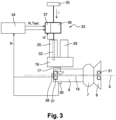
- FIG. 2 shows an axial sectional view of a turbomachine with a longitudinal axis X, and in particular, a dual-flow turbomachine according to the invention.
- This turbomachine 1 generally comprises a nacelle 2 enclosing a gas generator 3 with a longitudinal axis X upstream of which a fan 3 is mounted.
- the terms "upstream” and “downstream” are defined in relation to the circulation of gases in the turbomachine 1, and substantially along the longitudinal axis X.
- the gas generator 3 comprises from upstream to downstream a low-pressure compressor 5, a high-pressure compressor 6, a combustion chamber 7, a high-pressure turbine 8 and a low-pressure turbine 9.
- the turbomachine 1 comprises a primary vein 10 in which a primary flow circulates which passes through the gas generator 3.
- the latter also comprises a secondary vein 11 in which a secondary flow circulates between the nacelle 2 and a casing, here an intermediate casing 12 surrounding the gas generator 3.
- a fan casing 13 which is integral with the nacelle 2, delimits fan blades 14 which extend radially from a hub 15.
- radial is defined relative to a radial axis perpendicular to the longitudinal axis X of the turbomachine.
- a casing arm 16 extends radially between the intermediate casing 12 and the nacelle 2 and is substantially tubular.
- the casing arm 16 is traversed radially by a radial input shaft 17.
- the latter is connected to a drive shaft 18 of the turbomachine coaxial with the longitudinal axis X.
- the radial input shaft 17 ensures a transmission of power between the drive shaft 18 and an accessory box 19 or accessory relay known by the English designation of “Accessory GearBox” (abbreviated AGB).
- the drive shaft 18 drives the members of the accessory box 19 in rotation when the latter is rotating.
- a first power transmission mechanism 21 is arranged between the radial input shaft 17 and the drive shaft 18.
- the first power transmission mechanism 21 comprises a first pinion 22 secured to the radial input shaft 17.
- the first mechanism 21 also comprises a second pinion 23 secured to the drive shaft 18.
- the first pinion 22 meshes with the second pinion 23.
- the first and second pinions 22, 23 are conical so as to form an angle transmission between the radial input shaft 17 and the drive shaft 18.
- a second power transmission mechanism 24 is arranged between the radial input shaft 17 and the drive shaft 18.
- the second power transmission mechanism 24 comprises a third pinion 26 and a fourth pinion 27.
- the third pinion 26 is here secured to a shaft main shaft 25 connected to the accessory housing 19.
- the main shaft 25 is substantially parallel to the longitudinal axis X.
- the fourth pinion 27, it is integral with the radial input shaft 17.
- the fourth pinion 27 is opposite along the radial axis to the first pinion 22.
- the third and fourth pinions 26, 27 are conical so as to form an angle transmission between the main shaft 25 and the radial input shaft 17.
- the drive shaft 18 is the high-pressure shaft which connects the high-pressure compressor 6 and the high-pressure turbine 8 so as to form a high-pressure body.
- the accessory housing 19 comprises several gear wheels mounted in series.
- first gear wheels are integral with the main shaft 25 of the accessory housing 19.
- Each first gear wheel meshes with a second gear wheel connected to an accessory or equipment of the turbomachine via a secondary shaft.
- the main shaft 25, the first and second gear wheels and the secondary shafts are housed in a casing 30 of the accessory housing.
- These accessories coupled to the housing 19 include for example, as we have seen in the preamble, a starter 20, fuel, lubrication, hydraulic pumps 29, an oil separator (not shown), an electric generator (not shown), etc.
- the starter 20 makes it possible to start the turbomachine 1 and to generate electrical energy after starting via the first and second mechanisms 21, 24.
- the starter 20 drives the high pressure shaft 18 in rotation.
- the accessory box 19 is installed in the nacelle 2 as illustrated in the figure 2 .
- the accessory housing 19 is mounted outside the secondary vein 11.
- the starter 20 is mounted on the accessory housing 19, it is therefore able to drive the high pressure shaft 18 via the accessory housing 19 and the radial input shaft 17.
- the starter 20 drives the high-pressure shaft 18 without the accessory housing 19 participating in the transmission.
- the accessory housing 19 is then driven by the starter 20 via the high-pressure shaft.
- the turbomachine also comprises an oil circuit for lubricating rolling elements such as bearings 31 mounted on the high-pressure shaft 18, pinions and toothed wheels and/or bearings of the secondary shafts in the accessory housing 19.
- the starter 20 is part of a starting system of the turbomachine to drive the high-pressure shaft 18 up to a rotational speed generating the starting of the turbomachine.
- the high-pressure shaft 18 is driven in rotation from a first speed V0 which can be zero, corresponding to the stopping of the turbomachine, or which can be relatively low in the normal direction of rotation, up to a second rotational speed V2 allowing the turbomachine to operate autonomously.
- V0 which can be zero, corresponding to the stopping of the turbomachine, or which can be relatively low in the normal direction of rotation
- V2 allowing the turbomachine to operate autonomously.
- the second rotational speed V2 corresponds to the rotational speed N1 mentioned above with reference to the figure 1 , which allows the starting of the turbomachine and in particular the ignition of the combustion chamber 7.
- the starter 20 comprises an output shaft 32 which is coupled to the accessory box 19 to deliver a starting torque to the high pressure shaft 18.
- the starting system comprises an electronic control module 33 (called SCU) which is intended to control the starter 20.
- This control module electronic unit 33 communicates with an electronic unit 34 of the turbomachine.
- the electronic unit 34 may be a computer (called ECU in English for “Electronic Control Unit”).
- the control module 33 receives from the electronic unit indications of the rotation speed of the high-pressure shaft 18, temperature measurements, and starting signals as described below.
- the control module 33 also receives directly a current intensity Id measured in the starter 20.
- the starter 20 is an electric starter and is powered by an electrical power source.
- the latter may be a battery, an external power supply such as an electric park socket, or the aircraft's on-board network.
- the electric starter is a three-stage synchronous machine. Other technologies are possible such as an asynchronous machine, a permanent magnet synchronous machine, a direct current synchronous machine. The operating principle is similar for torque control.
- the starter is a starter-generator connected to the high-pressure shaft and capable of operating in generator mode at the end of the start-up phase.
- the starter-generator is a variable frequency starter known by the English designation “Variable Frequency Starter Generator” (abbreviated VFSG).
- the starter is considered to be an electric starter, for example a starter-generator.
- the control module 33 is also connected to an electrical circuit 35 of the aircraft on which the turbomachine is mounted and which is coupled to the electrical power source.
- the electrical circuit 35 transfers an electrical power i which is delivered to the starter 20 via a power transfer device 36 which the control module 33 comprises.
- the control module 33 further comprises a control device 37 which controls the power transfer device 36 as a function of the starting torque to be exerted. It may be envisaged to include this control device 37 in the electronic unit 34.
- the control module 33 then controls the torque developed by the starter 20 by regulating the electrical power i which is transmitted to the starter 20.
- the accessory box 19 therefore participates in the starting of the turbomachine by transforming the torque exerted on the output shaft 32 of the starter into a starting torque exerted on the high-pressure shaft 18.
- the rotational energy of the high-pressure shaft 18 is distributed to the other accessories essential for the operation of the turbomachine and the aircraft via the radial input shaft 17 and the first and second mechanisms 21, 24.
- the starting method comprises a step of pre-start prior to a conventional start-up step of the turbomachine where the drive shaft, here the high pressure shaft 18, is rotated from the first zero rotation speed to the second rotation speed generating the start-up of the turbomachine.
- a first start signal is generated to control the driving of the high-pressure shaft 18 in a first direction of rotation, then in a second opposite direction of rotation about the longitudinal axis X, and this operation is repeated alternately.
- a second start signal is then generated to control the high-pressure shaft of the turbomachine in a normal direction of rotation up to the second rotation speed V2 generating the starting of the turbomachine as we will see in the remainder of the description.
- the first start signal is generated by the control module 33 and is transmitted to the starter 20 driving the high-pressure shaft 18 in the first and second directions of rotation alternately.
- the high-pressure shaft 18 is controlled so as to make angular “back-and-forth” movements around the longitudinal axis of the turbomachine to perform several oscillations.
- the term “oscillation” means rotational movements in clockwise and counterclockwise directions around the longitudinal axis of the turbomachine.
- the rotational drive of the high pressure shaft 18 generates the rotational drive of the accessories coupled to the accessory housing 19 connected thereto, via the radial input shaft 17, in the first and second directions of rotation alternately.
- This sequence of alternating rotations allows the lubricant contained and trapped in the bearings of the accessory housing to be sufficiently heated by viscous friction, so as to reduce its viscosity. Indeed, by oscillations of the torque applied by the starter 20 at the start of the pre-start sequence, which cause small amplitudes of alternating rotations of the high-pressure shaft 18, it is possible to locally heat the lubricant without forcing the torque.
- the oscillations of the torque successively compress and decompress the frozen lubricant, gradually increasing the oscillation amplitude, which heats the lubricant without causing it to circulate significantly and without forcing it in the same direction.
- the lubricant can be sufficiently heated by viscous friction, so that its viscosity is significantly reduced when it is evacuated from the bearings.
- the oscillations of the torque applied by the starter 20, during the pre-start sequence are carried out without forcing the torque applied to the accessory housing, the internal components of which thus avoid being damaged.
- the oscillations of the high-pressure shaft 18 will also make it possible to heat and evacuate the lubricant present in the bearings 30 of the shaft 18, and thus facilitate the starting of the turbomachine.
- the starting system 20 also comprises a means 38 for determining angular displacement intended to identify the direction of rotation and the speed of rotation of the high pressure shaft 18.
- the means 38 for determining angular displacement is connected to the electronic unit 34.
- the means for determining angular displacement here comprises a sensor, for example of the resolver type.
- the starter 20 applies a first torque, which can be referred to as a pre-start torque, to the high-pressure shaft 18 for a first predetermined duration. Then the starter 20 applies a second pre-start torque to the high-pressure shaft 18 to drive it in the second opposite direction of rotation for a second predetermined duration. This makes it possible to locally heat the lubricant frozen in the turbomachine.
- the sensor 38 transmits a signal indicating the direction of rotation of the turbomachine to the electronic unit before the starter 20 applies the pre-start torques to the high-power shaft of the turbomachine.
- the first and second predetermined durations are for example between 1 s and 10 s respectively, but alternatively much shorter durations can be provided so as to generate micro-oscillations.
- the high-pressure shaft 18 When the high-pressure shaft 18 is rotated in the first and second directions of rotation, it oscillates by an angular amplitude that can be between -45° and +45° relative to a reference position of the turbomachine.
- the reference position corresponds to the rest position of the turbomachine in which we consider a point located in a radial plane perpendicular to the longitudinal axis of the turbomachine.
- the angular amplitude may increase progressively during the total duration of the pre-start step to reach, for example, values between -90° and +90° relative to the reference position.
- the increase in the angular amplitude may be caused by a progressive increase in the respective value of the first and second starting torques applied to the high-pressure shaft 18 and/or in the duration of application of the torque in each direction.
- the method comprises a step of determining the outside temperature in which when an indicator signal of the outside temperature Text of the turbomachine is less than or equal to a threshold temperature value Tseuil, the first start signal is generated to drive the high-pressure shaft 18 in the first and second directions of rotation to oscillate. In this way, the pre-start step is not applied systematically.
- This threshold temperature value is determined during the development phases of the turbomachine and is stored in a memory of the electronic unit 34 or of the control device 37.
- the turbomachine comprises an outside temperature sensor 39 which is connected to the electronic unit 34. The latter receives an indicator signal of the outside temperature measured in response to the temperature measured by the temperature sensor and compares it to the threshold temperature value Tseuil.
- This threshold temperature value can be of the order of -30°C.
- the pre-start step is carried out for a determined total duration and/or with a predetermined pre-start rotation speed.
- the determined total duration of the oscillations can be quite short.
- the determined total duration DT is between 10s and 300s.
- the maximum pre-start rotation speed reached by the high-pressure shaft 18 can be, for example, between 100 rpm and 1000 rpm.
- the determined total duration of the oscillations and/or the pre-start rotational speed is/are determined as a function of the outside temperature Text of the turbomachine. It is possible, for example, during the development phase of the turbomachine, to define for each outside temperature value Text in which the turbomachine is to operate, a total duration and/or a pre-start rotational speed for driving the high-pressure shaft 18 into rotation. The total durations and/or the pre-start rotational speeds can be stored in the form of tables. Depending on the measured outside temperature value Text, the control module 33 applies the determined total duration and/or the pre-start rotational speed V for the high-pressure shaft 18.
- the determined total duration and/or the pre-start rotation speed can also be determined as a function of the temperature of the lubricant in the vicinity of the accessory housing 19.
- the method comprises a step of determining a lubricant temperature in which a temperature of the lubricant is measured in the vicinity of the accessory housing 19.
- a signal indicating the lubricant temperature in response to the measured temperature Tlub is transmitted to the electronic unit 34.
- This signal indicating the measured temperature Tlub is compared with a lubricant temperature value Tlubthreshold.
- the second start signal of the turbomachine is generated.
- the second start signal is also generated by the control module 33 and is transmitted to the starter 20 driving the high-pressure shaft 18 in its normal direction of rotation.
- This second start signal may be preceded by an oscillation stop signal transmitted to the starter 20.
- the temperature of the lubricant is measured by means of a lubricant temperature sensor (not shown). The latter is advantageously, but not limited to, placed in the accessory housing 19 and is also connected to the electronic unit 34. When the measured temperature is less than or equal to the threshold temperature value, the electronic unit 34 emits a control signal for maintaining the pre-start step.
- the determined total duration and/or the pre-start rotation speed may also be determined as a function of a resistive torque exerted by the turbomachine.
- the method comprises a step of determining the resistive torque exerted by the turbomachine.
- a torque indicator signal in response to the measured torque CM is transmitted to the electronic unit 34.
- This torque indicator signal is compared to a threshold torque value Cseuil for a given rotation speed. As long as the measured resistive torque is greater than the threshold torque value, this means that the viscosity of the lubricant is not sufficiently reduced to allow starting, the pre-start step is therefore maintained.
- the electronic unit transmits a control signal to the control module 33 for maintaining the pre-start step.
- the second start signal is generated to control the drive shaft of the turbomachine in a normal direction of rotation.
- the control module 33 transmits to the starter 20 the second start signal of the turbomachine.
- this second start signal can be preceded by a control signal for stopping the prestart step. Determining the torque exerted by the turbomachine makes it possible to determine the viscosity of the lubricant in the accessory housing 19. In other words, with low torques, the viscosity of the lubricant is reduced which implies that the lubricant is heated.
- Different torque values for different rotational speeds of the high pressure shaft are stored in the memory of the electronic unit 34 or in the control device 37.
- the second starting signal is transmitted to the starter 20 so that the latter drives the high-pressure shaft 18 of the turbomachine in a normal starting rotation direction and in which the high-pressure shaft 18 is rotated from the first speed V0 which may be zero to the second rotation speed V2 generating the starting of the turbomachine.
- the pre-starting rotation speed of the drive shaft during the pre-starting step is lower than that of the drive shaft during the starting step.
- the drive shaft, in the starting step cannot drive the starting of the turbomachine to avoid the resistive torque.
- This second start signal can be emitted following a start command from the pilot to the electronic unit 34.
- the electronic unit 34 can emit, at the end of the stop control signal of the pre-start step, an information signal to the pilot corresponding to a viscosity state of the lubricant in the accessory housing 19 or the outside temperature so that the latter decides to start the turbomachine himself.
- This information can be presented in the form of visual or audible information.
- the viscosity state of the lubricant is obtained following the step of determining the temperature of the lubricant in the accessory housing.
- the step of determining the temperature of the lubricant in the vicinity of the accessory housing can be carried out before the pre-start step.
- the lubricant comprises an oil capable of lubricating and cooling parts of the turbomachine.
- the method comprises a waiting step in which the second start signal is generated after a waiting period. During this step, a signal indicating the direction of rotation or the stopping of the rotation of the high-pressure shaft 18 can be transmitted to the electronic unit 34 in order to verify that the starter 20 is ready to drive the high-pressure shaft 18 in the normal direction of rotation.
- the starter applies a starting torque to the high-pressure shaft 18.
- the second rotation speed is used to ignite the combustion chamber supplied with compressed air by the compressor.
- the high-pressure shaft 18 undergoes continuous acceleration until it reaches speed V2.
- the accessory box 19 is located in the nacelle.
- the starting method according to the invention also applies to turbomachine architectures having other arrangements of one or more accessory boxes, for example an architecture as described in the publication FR2981986A1 , in which the accessory housing is located in an inter-vein compartment of a dual-flow turbomachine.
Landscapes
- Engineering & Computer Science (AREA)
- Mechanical Engineering (AREA)
- General Engineering & Computer Science (AREA)
- Chemical & Material Sciences (AREA)
- Combustion & Propulsion (AREA)
- Control Of Turbines (AREA)
- Structures Of Non-Positive Displacement Pumps (AREA)
- Control Of Positive-Displacement Air Blowers (AREA)
Claims (16)
- Verfahren zum Kaltwetterstart eines Turbotriebwerks, bei dem die Außentemperatur unter -10°C oder sogar unter -30°C liegt, wobei das Turbotriebwerk ein Startsystem zum Drehantrieb einer Antriebswelle (18) des Turbotriebwerks (100) umfasst, wobei das Verfahren die folgenden Schritte umfasst:- einen Vorstartschritt, bei dem ein erstes Startsignal erzeugt wird, um die Antriebswelle (18) in einer ersten Drehrichtung um eine Längsachse (X) und in einer zweiten, entgegengesetzten Drehrichtung abwechselnd so zu steuern, dass Schwingungen erzeugt werden, und- einen Startschritt, bei dem ein zweites Startsignal erzeugt wird, um die Antriebswelle (18) des Turbotriebwerks in eine normale Drehrichtung zu steuern, die einer der ersten und zweiten Drehrichtung entspricht, wobei die Antriebswelle (18) bis zu einer Drehgeschwindigkeit (V2) gedreht wird, die den Start des Turbotriebwerks erzeugt.
- Verfahren nach dem vorstehenden Anspruch, dadurch gekennzeichnet, dass die Antriebswelle (18) die Welle eines Hochdruckkörpers des Turbotriebwerks ist, der Doppelkörper und Doppelstrom aufweist.
- Verfahren nach einem der vorstehenden Ansprüche, dadurch gekennzeichnet, dass die Antriebswelle (18) mit einem Zubehörgehäuse (19) gekoppelt ist, das ein Schmiermittel umfasst, dessen Viskosität bei niedrigen Temperaturen, insbesondere bei einer Temperatur unter -10°C und insbesondere unter -30°C, ansteigt.
- Verfahren nach einem der vorstehenden Ansprüche, dadurch gekennzeichnet, dass der Vorstartschritt während einer bestimmten Gesamtdauer und/oder bei einer vorbestimmten Vorstartdrehgeschwindigkeit der Antriebswelle durchgeführt wird.
- Verfahren nach Anspruch 4, dadurch gekennzeichnet, dass die vorbestimmte Gesamtdauer des Vorstartschritts und/oder die vorbestimmte Vorstartdrehgeschwindigkeit eine Funktion der Schmiermitteltemperatur in der Nähe des Zubehörgehäuses oder eines von dem Turbotriebwerk ausgeübten Widerstandsdrehmoments oder der Temperatur außerhalb des Turbotriebwerks ist/ sind.
- Verfahren nach einem der vorstehenden Ansprüche, dadurch gekennzeichnet, dass es einen Schritt zur Bestimmung einer Außentemperatur umfasst, wobei, wenn ein die Außentemperatur (Text) des Turbotriebwerks als Reaktion auf eine gemessene Temperatur anzeigendes Signal mit einem Temperaturschwellenwert verglichen wird, so dass, wenn die gemessene Außentemperatur gleich oder kleiner als der Temperaturschwellenwert ist, das erste Startsignal erzeugt wird.
- Verfahren nach einem der Ansprüche 3 bis 6, dadurch gekennzeichnet, dass es einen Schritt zur Bestimmung einer Schmiermitteltemperatur umfasst, wobei ein die Schmiermitteltemperatur anzeigendes Signal als Reaktion auf eine in der Nähe des Zubehörgehäuses (19) oder darin gemessene Schmiermitteltemperatur (Tlub) mit einem Schmiermittelschwellentemperaturwert (Tlubseuil) verglichen wird, so dass, wenn die gemessene Schmiermitteltemperatur (Tlub) größer ist als der Schmiermittelschwellentemperaturwert (Tlubseuil), das zweite Startsignal erzeugt wird, um die Antriebswelle (18) in einer normalen Drehrichtung anzutreiben.
- Verfahren nach einem der vorstehenden Ansprüche, dadurch gekennzeichnet, dass es einen Schritt zur Bestimmung eines von dem Turbotriebwerk ausgeübten Widerstandsmoments umfasst, wobei ein das Drehmoment anzeigendes Signal als Reaktion auf das gemessene Widerstandsmoment mit einem Drehmomentschwellenwert (Cseuil) für eine gegebene Drehgeschwindigkeit des Turbotriebwerks verglichen wird, so dass, wenn das gemessene Widerstandsmoment kleiner oder gleich dem Drehmomentschwellenwert (Cseuil) ist, das zweite Startsignal erzeugt wird.
- Verfahren nach einem der vorstehenden Ansprüche, dadurch gekennzeichnet, dass das zweite Startsignal nach einer vorbestimmten Wartezeit erzeugt wird, die auf die Beendigung des Vorstartschritts folgt, wobei die Geschwindigkeit (V0) der Antriebswelle (18) Null ist, wenn der Startschritt eingeleitet wird.
- Verfahren nach einem der Ansprüche 4 bis 9, dadurch gekennzeichnet, dass die Vorstartdrehgeschwindigkeit unter derjenigen der Drehgeschwindigkeit (V2) liegt, die den Start des Turbotriebwerks erzeugt.
- Verfahren nach dem vorstehenden Anspruch, dadurch gekennzeichnet, dass die maximale Vorstartdrehgeschwindigkeit der Antriebswelle (18), die während des Vorstarts erreicht wird, im Bereich zwischen 100 U/min bis 1000 U/min liegt.
- Verfahren nach einem der vorstehenden Ansprüche, dadurch gekennzeichnet, dass die Dauer des Vorstartschritts vorbestimmt ist und im Bereich zwischen 10s und 300s liegt.
- Kaltwetterstartsystem für ein Turbotriebwerk (100), wobei die Außentemperatur unter -10°C oder sogar unter -30°C liegt, wobei das Startsystem ein elektronisches Steuermodul (33), einen Starter (20), der dazu bestimmt ist, von dem elektronischen Steuermodul (33) gesteuert zu werden, und eine Antriebswelle (18) des Turbotriebwerks, die mit dem Starter (20) gekoppelt ist, umfasst, wobei das elektronische Steuermodul (33) angeordnet ist, um ein erstes Startsignal zu erzeugen, um die Drehung der Antriebswelle (18) in einer ersten Drehrichtung und in einer zweiten, entgegengesetzten Drehrichtung, abwechselnd und so zu steuern, dass Schwingungen erzeugt werden, und um ein zweites Startsignal zu erzeugen, um die Drehung der Antriebswelle (18) in einer normalen Drehrichtung zu steuern, die einer der ersten und der zweiten Drehrichtung entspricht, wobei die Antriebswelle (18) bis zu einer Drehgeschwindigkeit (V2) gedreht wird, die den Start der Turbomaschine erzeugt.
- Startsystem nach dem vorstehenden Anspruch, dadurch gekennzeichnet, dass die Antriebswelle (18) mit einem Zubehörgehäuse (19) gekoppelt ist, auf dem der Starter (20) montiert ist, wobei letzterer in der Lage ist, die Antriebswelle (18) in der ersten und der zweiten entgegengesetzten Drehrichtung abwechselnd zu betätigen.
- Startsystem nach einem der Ansprüche 13 oder 14, dadurch gekennzeichnet, dass es ein Mittel zur Erfassung der Temperatur umfasst, das mit dem elektronischen Steuermodul (33) verbunden und dazu konfiguriert ist, ein Signal zu liefern, das die Temperatur des Schmiermittels in der Nähe eines Zubehörgehäuses (19) des Turbotriebwerks anzeigt.
- Startsystem nach einem der Ansprüche 13 bis 15, dadurch gekennzeichnet, dass es Mittel zur Bestimmung des Drehmoments umfasst, die mit dem elektronischen Steuermodul (33) verbunden und dazu konfiguriert sind, ein Signal zu liefern, das das von dem Turbotriebwerk ausgeübte Widerstandsmoment anzeigt.
Applications Claiming Priority (2)
| Application Number | Priority Date | Filing Date | Title |
|---|---|---|---|
| FR1763361A FR3076321B1 (fr) | 2017-12-29 | 2017-12-29 | Procede de demarrage de turbomachine par temps froid et systeme de demarrage de turbomachine |
| PCT/FR2018/053394 WO2019129952A1 (fr) | 2017-12-29 | 2018-12-19 | Procede de demarrage de turbomachine par temps froid et systeme de demarrage de turbomachine |
Publications (2)
| Publication Number | Publication Date |
|---|---|
| EP3732353A1 EP3732353A1 (de) | 2020-11-04 |
| EP3732353B1 true EP3732353B1 (de) | 2024-12-04 |
Family
ID=61187568
Family Applications (1)
| Application Number | Title | Priority Date | Filing Date |
|---|---|---|---|
| EP18842634.0A Active EP3732353B1 (de) | 2017-12-29 | 2018-12-19 | Verfahren zum starten eines turbinentriebwerks in kaltem wetter und system zum starten eines turbinentriebwerks |
Country Status (5)
| Country | Link |
|---|---|
| US (2) | US11339683B2 (de) |
| EP (1) | EP3732353B1 (de) |
| CN (1) | CN111512023B (de) |
| FR (1) | FR3076321B1 (de) |
| WO (1) | WO2019129952A1 (de) |
Families Citing this family (3)
| Publication number | Priority date | Publication date | Assignee | Title |
|---|---|---|---|---|
| US11313740B2 (en) | 2019-02-08 | 2022-04-26 | Fairfield Manufacturing Company, Inc. | Gearbox temperature measurement device |
| CN117382895A (zh) * | 2023-10-13 | 2024-01-12 | 中国航发沈阳发动机研究所 | 一种航空发动机暖机状态座舱显示方法 |
| FR3163111B1 (fr) * | 2024-06-05 | 2026-04-24 | Stellantis Auto Sas | PROCEDE DE PILOTAGE D’UN SYSTEME THERMODYNAMIQUE d’un véhicule automobile |
Family Cites Families (15)
| Publication number | Priority date | Publication date | Assignee | Title |
|---|---|---|---|---|
| US5051670A (en) | 1990-07-30 | 1991-09-24 | Aircraft Parts Corp. | Aircraft DC starter-generator torque controller |
| US5741965A (en) * | 1996-11-29 | 1998-04-21 | Hernandez; Carlos M. | Aircraft jet engine testing tool |
| JPH114598A (ja) * | 1997-06-10 | 1999-01-06 | Hitachi Ltd | タービンの起動方法 |
| US7434406B2 (en) * | 2005-05-10 | 2008-10-14 | Honeywell International Inc. | Drive for using a direct driven generator to start a counter-rotating multi-spool gas turbine engine |
| WO2007102738A1 (en) * | 2006-03-08 | 2007-09-13 | Dynatrend As | A method and device for cleaning an axial compressor |
| FR2915238A1 (fr) * | 2007-04-23 | 2008-10-24 | Airbus France Sa | Procede et systeme pour le demarrage d'un turbomoteur par temps froid. |
| FR2970304B1 (fr) * | 2011-01-11 | 2013-02-08 | Turbomeca | Procede de demarrage d'une turbomachine |
| US9745897B2 (en) * | 2011-01-13 | 2017-08-29 | Hamilton Sundstrand Corporation | Anti-windmilling starter generator |
| FR2981986B1 (fr) | 2011-10-26 | 2016-03-04 | Snecma | Boitier d'entrainement d'accessoires pour turboreacteur |
| EP2644841A1 (de) * | 2012-03-29 | 2013-10-02 | Alstom Technology Ltd | Verfahren zum Betreiben eines Turbinenmotors nach Flammenaus |
| US9428267B2 (en) * | 2014-01-06 | 2016-08-30 | Sikorsky Aircraft Corporation | In-flight mechanically assisted turbine engine starting system |
| US9945266B2 (en) * | 2014-08-28 | 2018-04-17 | General Electric Company | Combined cycle power plant thermal energy conservation |
| FR3025252B1 (fr) | 2014-08-29 | 2021-10-29 | Microturbo | Dispositif et procede de demarrage d'une turbine a gaz, procede de regulation de la vitesse de rotation d'une turbine a gaz, et turbine a gaz et turbomoteur associes |
| EP3336320B1 (de) * | 2016-12-14 | 2020-08-12 | Airbus Operations, S.L. | Ölheizungssystem für ein turbinentriebwerk zur reduzierung des anfahrmoments |
| US11073086B2 (en) * | 2018-11-27 | 2021-07-27 | The Boeing Company | Apparatus, assemblies, and methods for mitigating thermal bow in the rotor of an engine at start-up |
-
2017
- 2017-12-29 FR FR1763361A patent/FR3076321B1/fr active Active
-
2018
- 2018-12-19 WO PCT/FR2018/053394 patent/WO2019129952A1/fr not_active Ceased
- 2018-12-19 EP EP18842634.0A patent/EP3732353B1/de active Active
- 2018-12-19 US US16/958,012 patent/US11339683B2/en active Active
- 2018-12-19 CN CN201880083575.0A patent/CN111512023B/zh active Active
-
2022
- 2022-01-13 US US17/575,198 patent/US20220145804A1/en not_active Abandoned
Also Published As
| Publication number | Publication date |
|---|---|
| FR3076321A1 (fr) | 2019-07-05 |
| WO2019129952A1 (fr) | 2019-07-04 |
| CN111512023A (zh) | 2020-08-07 |
| CN111512023B (zh) | 2023-02-17 |
| EP3732353A1 (de) | 2020-11-04 |
| US11339683B2 (en) | 2022-05-24 |
| FR3076321B1 (fr) | 2022-02-18 |
| US20220145804A1 (en) | 2022-05-12 |
| US20210062721A1 (en) | 2021-03-04 |
Similar Documents
| Publication | Publication Date | Title |
|---|---|---|
| EP3732353B1 (de) | Verfahren zum starten eines turbinentriebwerks in kaltem wetter und system zum starten eines turbinentriebwerks | |
| WO2017203155A1 (fr) | Turbomachine d'aeronef avec reducteur epicycloidal a rapport de reduction variable | |
| EP3047117B1 (de) | System und verfahren zum notstarten flugzeugturbomaschinen | |
| EP3208193B1 (de) | Vorrichtung und methode zur steuerung einer kupplung zwischen dem motor und dem hauptleistungsübertragungsgetriebe eines luftfahrzeugs | |
| FR3020838B1 (fr) | Moteur a turbine a gaz a demarreur en prise avec un corps basse pression | |
| WO2022208021A1 (fr) | Procédé de démarrage piloté d'une turbine a gaz d'un aéronef et systeme correspondant | |
| EP4237671B1 (de) | Freiturbinenturbogenerator mit einer reversiblen elektrischen maschine, die an die freiturbine gekoppelt ist | |
| EP4179185B1 (de) | Startverfahren für ein flugzeugtriebwerk | |
| FR3028887B1 (fr) | Procede et circuit de lubrification pour une turbomachine utilisant des moyens electriques | |
| WO2021115996A1 (fr) | Groupe auxiliaire de puissance comprenant un générateur de gaz à entrainement direct avec un générateur électrique et un boîtier d'accessoires | |
| EP4320341B1 (de) | Turbomaschine mit freier turbine und mit einer durch die freie turbine angetriebenen vorrichtung | |
| FR3060499A1 (fr) | Procede de gestion d'une phase transitoire du demarrage d'un moteur thermique par une machine electrique | |
| EP3387238B1 (de) | Verfahren zur verwaltung der verwendung eines elektrischen verdichters in einem fahrzeug mit automatikgetriebe | |
| FR2960592A1 (fr) | Procede de demarrage d'un moteur d'aeronef | |
| FR3138411A1 (fr) | Ensemble propulsif amélioré pour aéronef hybridé multi moteurs | |
| EP4237666B1 (de) | Turbomaschine mit freier turbine und mit einer durch die freie turbine angetriebenen vorrichtung | |
| FR3076322A1 (fr) | Procede et dispositif de demarrage pour une turbomachine par temps froid | |
| FR3109963A1 (fr) | Module de lubrification d’un reducteur de soufflante de turbomachine en phase d’autorotation de la soufflante | |
| EP4705624A1 (de) | Zubehörantriebssystem mit einer mehrscheibenkupplung und einer elektrischen generatormaschine | |
| WO2024261430A1 (fr) | Turbomachine à hybridation électrique parallèle | |
| FR3152291A1 (fr) | Systeme d’injection de couple a reduction et a double sens de rotation dans une turbomachine | |
| FR3138828A1 (fr) | Procédé d’assistance à la propulsion par détection d’une défaillance d’un turbomoteur d’un aéronef | |
| FR3092141A1 (fr) | Turbomachine comprenant un système anti-fléchissement d’un arbre du rotor utilisant de l’air comprimé. |
Legal Events
| Date | Code | Title | Description |
|---|---|---|---|
| STAA | Information on the status of an ep patent application or granted ep patent |
Free format text: STATUS: UNKNOWN |
|
| STAA | Information on the status of an ep patent application or granted ep patent |
Free format text: STATUS: THE INTERNATIONAL PUBLICATION HAS BEEN MADE |
|
| PUAI | Public reference made under article 153(3) epc to a published international application that has entered the european phase |
Free format text: ORIGINAL CODE: 0009012 |
|
| STAA | Information on the status of an ep patent application or granted ep patent |
Free format text: STATUS: REQUEST FOR EXAMINATION WAS MADE |
|
| 17P | Request for examination filed |
Effective date: 20200618 |
|
| AK | Designated contracting states |
Kind code of ref document: A1 Designated state(s): AL AT BE BG CH CY CZ DE DK EE ES FI FR GB GR HR HU IE IS IT LI LT LU LV MC MK MT NL NO PL PT RO RS SE SI SK SM TR |
|
| AX | Request for extension of the european patent |
Extension state: BA ME |
|
| DAV | Request for validation of the european patent (deleted) | ||
| DAX | Request for extension of the european patent (deleted) | ||
| STAA | Information on the status of an ep patent application or granted ep patent |
Free format text: STATUS: EXAMINATION IS IN PROGRESS |
|
| 17Q | First examination report despatched |
Effective date: 20220715 |
|
| GRAP | Despatch of communication of intention to grant a patent |
Free format text: ORIGINAL CODE: EPIDOSNIGR1 |
|
| STAA | Information on the status of an ep patent application or granted ep patent |
Free format text: STATUS: GRANT OF PATENT IS INTENDED |
|
| INTG | Intention to grant announced |
Effective date: 20240409 |
|
| GRAJ | Information related to disapproval of communication of intention to grant by the applicant or resumption of examination proceedings by the epo deleted |
Free format text: ORIGINAL CODE: EPIDOSDIGR1 |
|
| STAA | Information on the status of an ep patent application or granted ep patent |
Free format text: STATUS: EXAMINATION IS IN PROGRESS |
|
| GRAP | Despatch of communication of intention to grant a patent |
Free format text: ORIGINAL CODE: EPIDOSNIGR1 |
|
| STAA | Information on the status of an ep patent application or granted ep patent |
Free format text: STATUS: GRANT OF PATENT IS INTENDED |
|
| GRAS | Grant fee paid |
Free format text: ORIGINAL CODE: EPIDOSNIGR3 |
|
| INTC | Intention to grant announced (deleted) | ||
| INTG | Intention to grant announced |
Effective date: 20240718 |
|
| GRAA | (expected) grant |
Free format text: ORIGINAL CODE: 0009210 |
|
| STAA | Information on the status of an ep patent application or granted ep patent |
Free format text: STATUS: THE PATENT HAS BEEN GRANTED |
|
| AK | Designated contracting states |
Kind code of ref document: B1 Designated state(s): AL AT BE BG CH CY CZ DE DK EE ES FI FR GB GR HR HU IE IS IT LI LT LU LV MC MK MT NL NO PL PT RO RS SE SI SK SM TR |
|
| REG | Reference to a national code |
Ref country code: GB Ref legal event code: FG4D Free format text: NOT ENGLISH |
|
| REG | Reference to a national code |
Ref country code: CH Ref legal event code: EP |
|
| REG | Reference to a national code |
Ref country code: DE Ref legal event code: R096 Ref document number: 602018077332 Country of ref document: DE |
|
| REG | Reference to a national code |
Ref country code: IE Ref legal event code: FG4D Free format text: LANGUAGE OF EP DOCUMENT: FRENCH |
|
| REG | Reference to a national code |
Ref country code: LT Ref legal event code: MG9D |
|
| REG | Reference to a national code |
Ref country code: NL Ref legal event code: MP Effective date: 20241204 |
|
| PG25 | Lapsed in a contracting state [announced via postgrant information from national office to epo] |
Ref country code: HR Free format text: LAPSE BECAUSE OF FAILURE TO SUBMIT A TRANSLATION OF THE DESCRIPTION OR TO PAY THE FEE WITHIN THE PRESCRIBED TIME-LIMIT Effective date: 20241204 |
|
| PG25 | Lapsed in a contracting state [announced via postgrant information from national office to epo] |
Ref country code: FI Free format text: LAPSE BECAUSE OF FAILURE TO SUBMIT A TRANSLATION OF THE DESCRIPTION OR TO PAY THE FEE WITHIN THE PRESCRIBED TIME-LIMIT Effective date: 20241204 |
|
| PG25 | Lapsed in a contracting state [announced via postgrant information from national office to epo] |
Ref country code: BG Free format text: LAPSE BECAUSE OF FAILURE TO SUBMIT A TRANSLATION OF THE DESCRIPTION OR TO PAY THE FEE WITHIN THE PRESCRIBED TIME-LIMIT Effective date: 20241204 |
|
| PG25 | Lapsed in a contracting state [announced via postgrant information from national office to epo] |
Ref country code: ES Free format text: LAPSE BECAUSE OF FAILURE TO SUBMIT A TRANSLATION OF THE DESCRIPTION OR TO PAY THE FEE WITHIN THE PRESCRIBED TIME-LIMIT Effective date: 20241204 |
|
| PG25 | Lapsed in a contracting state [announced via postgrant information from national office to epo] |
Ref country code: NO Free format text: LAPSE BECAUSE OF FAILURE TO SUBMIT A TRANSLATION OF THE DESCRIPTION OR TO PAY THE FEE WITHIN THE PRESCRIBED TIME-LIMIT Effective date: 20250304 |
|
| PG25 | Lapsed in a contracting state [announced via postgrant information from national office to epo] |
Ref country code: LV Free format text: LAPSE BECAUSE OF FAILURE TO SUBMIT A TRANSLATION OF THE DESCRIPTION OR TO PAY THE FEE WITHIN THE PRESCRIBED TIME-LIMIT Effective date: 20241204 Ref country code: GR Free format text: LAPSE BECAUSE OF FAILURE TO SUBMIT A TRANSLATION OF THE DESCRIPTION OR TO PAY THE FEE WITHIN THE PRESCRIBED TIME-LIMIT Effective date: 20250305 |
|
| PG25 | Lapsed in a contracting state [announced via postgrant information from national office to epo] |
Ref country code: RS Free format text: LAPSE BECAUSE OF FAILURE TO SUBMIT A TRANSLATION OF THE DESCRIPTION OR TO PAY THE FEE WITHIN THE PRESCRIBED TIME-LIMIT Effective date: 20250304 |
|
| PG25 | Lapsed in a contracting state [announced via postgrant information from national office to epo] |
Ref country code: NL Free format text: LAPSE BECAUSE OF FAILURE TO SUBMIT A TRANSLATION OF THE DESCRIPTION OR TO PAY THE FEE WITHIN THE PRESCRIBED TIME-LIMIT Effective date: 20241204 |
|
| REG | Reference to a national code |
Ref country code: AT Ref legal event code: MK05 Ref document number: 1748373 Country of ref document: AT Kind code of ref document: T Effective date: 20241204 |
|
| PG25 | Lapsed in a contracting state [announced via postgrant information from national office to epo] |
Ref country code: SM Free format text: LAPSE BECAUSE OF FAILURE TO SUBMIT A TRANSLATION OF THE DESCRIPTION OR TO PAY THE FEE WITHIN THE PRESCRIBED TIME-LIMIT Effective date: 20241204 |
|
| PG25 | Lapsed in a contracting state [announced via postgrant information from national office to epo] |
Ref country code: PL Free format text: LAPSE BECAUSE OF FAILURE TO SUBMIT A TRANSLATION OF THE DESCRIPTION OR TO PAY THE FEE WITHIN THE PRESCRIBED TIME-LIMIT Effective date: 20241204 |
|
| PG25 | Lapsed in a contracting state [announced via postgrant information from national office to epo] |
Ref country code: IS Free format text: LAPSE BECAUSE OF FAILURE TO SUBMIT A TRANSLATION OF THE DESCRIPTION OR TO PAY THE FEE WITHIN THE PRESCRIBED TIME-LIMIT Effective date: 20250404 |
|
| PG25 | Lapsed in a contracting state [announced via postgrant information from national office to epo] |
Ref country code: PT Free format text: LAPSE BECAUSE OF FAILURE TO SUBMIT A TRANSLATION OF THE DESCRIPTION OR TO PAY THE FEE WITHIN THE PRESCRIBED TIME-LIMIT Effective date: 20250404 |
|
| PG25 | Lapsed in a contracting state [announced via postgrant information from national office to epo] |
Ref country code: EE Free format text: LAPSE BECAUSE OF FAILURE TO SUBMIT A TRANSLATION OF THE DESCRIPTION OR TO PAY THE FEE WITHIN THE PRESCRIBED TIME-LIMIT Effective date: 20241204 |
|
| PG25 | Lapsed in a contracting state [announced via postgrant information from national office to epo] |
Ref country code: AT Free format text: LAPSE BECAUSE OF FAILURE TO SUBMIT A TRANSLATION OF THE DESCRIPTION OR TO PAY THE FEE WITHIN THE PRESCRIBED TIME-LIMIT Effective date: 20241204 Ref country code: RO Free format text: LAPSE BECAUSE OF FAILURE TO SUBMIT A TRANSLATION OF THE DESCRIPTION OR TO PAY THE FEE WITHIN THE PRESCRIBED TIME-LIMIT Effective date: 20241204 |
|
| PG25 | Lapsed in a contracting state [announced via postgrant information from national office to epo] |
Ref country code: SK Free format text: LAPSE BECAUSE OF FAILURE TO SUBMIT A TRANSLATION OF THE DESCRIPTION OR TO PAY THE FEE WITHIN THE PRESCRIBED TIME-LIMIT Effective date: 20241204 |
|
| PG25 | Lapsed in a contracting state [announced via postgrant information from national office to epo] |
Ref country code: CZ Free format text: LAPSE BECAUSE OF FAILURE TO SUBMIT A TRANSLATION OF THE DESCRIPTION OR TO PAY THE FEE WITHIN THE PRESCRIBED TIME-LIMIT Effective date: 20241204 |
|
| PG25 | Lapsed in a contracting state [announced via postgrant information from national office to epo] |
Ref country code: IT Free format text: LAPSE BECAUSE OF FAILURE TO SUBMIT A TRANSLATION OF THE DESCRIPTION OR TO PAY THE FEE WITHIN THE PRESCRIBED TIME-LIMIT Effective date: 20241204 |
|
| REG | Reference to a national code |
Ref country code: CH Ref legal event code: PL |
|
| PG25 | Lapsed in a contracting state [announced via postgrant information from national office to epo] |
Ref country code: LU Free format text: LAPSE BECAUSE OF NON-PAYMENT OF DUE FEES Effective date: 20241219 |
|
| REG | Reference to a national code |
Ref country code: DE Ref legal event code: R097 Ref document number: 602018077332 Country of ref document: DE |
|
| PG25 | Lapsed in a contracting state [announced via postgrant information from national office to epo] |
Ref country code: SE Free format text: LAPSE BECAUSE OF FAILURE TO SUBMIT A TRANSLATION OF THE DESCRIPTION OR TO PAY THE FEE WITHIN THE PRESCRIBED TIME-LIMIT Effective date: 20241204 |
|
| PG25 | Lapsed in a contracting state [announced via postgrant information from national office to epo] |
Ref country code: MC Free format text: LAPSE BECAUSE OF FAILURE TO SUBMIT A TRANSLATION OF THE DESCRIPTION OR TO PAY THE FEE WITHIN THE PRESCRIBED TIME-LIMIT Effective date: 20241204 |
|
| REG | Reference to a national code |
Ref country code: BE Ref legal event code: MM Effective date: 20241231 |
|
| PG25 | Lapsed in a contracting state [announced via postgrant information from national office to epo] |
Ref country code: DK Free format text: LAPSE BECAUSE OF FAILURE TO SUBMIT A TRANSLATION OF THE DESCRIPTION OR TO PAY THE FEE WITHIN THE PRESCRIBED TIME-LIMIT Effective date: 20241204 |
|
| PLBE | No opposition filed within time limit |
Free format text: ORIGINAL CODE: 0009261 |
|
| STAA | Information on the status of an ep patent application or granted ep patent |
Free format text: STATUS: NO OPPOSITION FILED WITHIN TIME LIMIT |
|
| PG25 | Lapsed in a contracting state [announced via postgrant information from national office to epo] |
Ref country code: BE Free format text: LAPSE BECAUSE OF NON-PAYMENT OF DUE FEES Effective date: 20241231 |
|
| PG25 | Lapsed in a contracting state [announced via postgrant information from national office to epo] |
Ref country code: CH Free format text: LAPSE BECAUSE OF NON-PAYMENT OF DUE FEES Effective date: 20241231 |
|
| PG25 | Lapsed in a contracting state [announced via postgrant information from national office to epo] |
Ref country code: IE Free format text: LAPSE BECAUSE OF NON-PAYMENT OF DUE FEES Effective date: 20241219 |
|
| 26N | No opposition filed |
Effective date: 20250905 |
|
| PGFP | Annual fee paid to national office [announced via postgrant information from national office to epo] |
Ref country code: GB Payment date: 20251229 Year of fee payment: 8 |
|
| PGFP | Annual fee paid to national office [announced via postgrant information from national office to epo] |
Ref country code: FR Payment date: 20251222 Year of fee payment: 8 |
|
| PGFP | Annual fee paid to national office [announced via postgrant information from national office to epo] |
Ref country code: DE Payment date: 20251222 Year of fee payment: 8 |