EP4237671B1 - Freiturbinenturbogenerator mit einer reversiblen elektrischen maschine, die an die freiturbine gekoppelt ist - Google Patents
Freiturbinenturbogenerator mit einer reversiblen elektrischen maschine, die an die freiturbine gekoppelt ist Download PDFInfo
- Publication number
- EP4237671B1 EP4237671B1 EP21810670.6A EP21810670A EP4237671B1 EP 4237671 B1 EP4237671 B1 EP 4237671B1 EP 21810670 A EP21810670 A EP 21810670A EP 4237671 B1 EP4237671 B1 EP 4237671B1
- Authority
- EP
- European Patent Office
- Prior art keywords
- turbomachine
- shaft
- gas generator
- free turbine
- electrical machine
- Prior art date
- Legal status (The legal status is an assumption and is not a legal conclusion. Google has not performed a legal analysis and makes no representation as to the accuracy of the status listed.)
- Active
Links
Images

Classifications
-
- F—MECHANICAL ENGINEERING; LIGHTING; HEATING; WEAPONS; BLASTING
- F02—COMBUSTION ENGINES; HOT-GAS OR COMBUSTION-PRODUCT ENGINE PLANTS
- F02C—GAS-TURBINE PLANTS; AIR INTAKES FOR JET-PROPULSION PLANTS; CONTROLLING FUEL SUPPLY IN AIR-BREATHING JET-PROPULSION PLANTS
- F02C3/00—Gas-turbine plants characterised by the use of combustion products as the working fluid
- F02C3/04—Gas-turbine plants characterised by the use of combustion products as the working fluid having a turbine driving a compressor
- F02C3/10—Gas-turbine plants characterised by the use of combustion products as the working fluid having a turbine driving a compressor with another turbine driving an output shaft but not driving the compressor
- F02C3/103—Gas-turbine plants characterised by the use of combustion products as the working fluid having a turbine driving a compressor with another turbine driving an output shaft but not driving the compressor the compressor being of the centrifugal type
-
- B—PERFORMING OPERATIONS; TRANSPORTING
- B64—AIRCRAFT; AVIATION; COSMONAUTICS
- B64D—EQUIPMENT FOR FITTING IN OR TO AIRCRAFT; FLIGHT SUITS; PARACHUTES; ARRANGEMENT OR MOUNTING OF POWER PLANTS OR PROPULSION TRANSMISSIONS IN AIRCRAFT
- B64D41/00—Power installations for auxiliary purposes
-
- F—MECHANICAL ENGINEERING; LIGHTING; HEATING; WEAPONS; BLASTING
- F01—MACHINES OR ENGINES IN GENERAL; ENGINE PLANTS IN GENERAL; STEAM ENGINES
- F01D—NON-POSITIVE DISPLACEMENT MACHINES OR ENGINES, e.g. STEAM TURBINES
- F01D15/00—Adaptations of machines or engines for special use; Combinations of engines with devices driven thereby
- F01D15/10—Adaptations for driving, or combinations with, electric generators
-
- F—MECHANICAL ENGINEERING; LIGHTING; HEATING; WEAPONS; BLASTING
- F02—COMBUSTION ENGINES; HOT-GAS OR COMBUSTION-PRODUCT ENGINE PLANTS
- F02C—GAS-TURBINE PLANTS; AIR INTAKES FOR JET-PROPULSION PLANTS; CONTROLLING FUEL SUPPLY IN AIR-BREATHING JET-PROPULSION PLANTS
- F02C3/00—Gas-turbine plants characterised by the use of combustion products as the working fluid
- F02C3/04—Gas-turbine plants characterised by the use of combustion products as the working fluid having a turbine driving a compressor
- F02C3/10—Gas-turbine plants characterised by the use of combustion products as the working fluid having a turbine driving a compressor with another turbine driving an output shaft but not driving the compressor
-
- F—MECHANICAL ENGINEERING; LIGHTING; HEATING; WEAPONS; BLASTING
- F02—COMBUSTION ENGINES; HOT-GAS OR COMBUSTION-PRODUCT ENGINE PLANTS
- F02C—GAS-TURBINE PLANTS; AIR INTAKES FOR JET-PROPULSION PLANTS; CONTROLLING FUEL SUPPLY IN AIR-BREATHING JET-PROPULSION PLANTS
- F02C3/00—Gas-turbine plants characterised by the use of combustion products as the working fluid
- F02C3/04—Gas-turbine plants characterised by the use of combustion products as the working fluid having a turbine driving a compressor
- F02C3/107—Gas-turbine plants characterised by the use of combustion products as the working fluid having a turbine driving a compressor with two or more rotors connected by power transmission
-
- F—MECHANICAL ENGINEERING; LIGHTING; HEATING; WEAPONS; BLASTING
- F02—COMBUSTION ENGINES; HOT-GAS OR COMBUSTION-PRODUCT ENGINE PLANTS
- F02C—GAS-TURBINE PLANTS; AIR INTAKES FOR JET-PROPULSION PLANTS; CONTROLLING FUEL SUPPLY IN AIR-BREATHING JET-PROPULSION PLANTS
- F02C7/00—Features, components parts, details or accessories, not provided for in, or of interest apart form groups F02C1/00 - F02C6/00; Air intakes for jet-propulsion plants
- F02C7/26—Starting; Ignition
- F02C7/268—Starting drives for the rotor, acting directly on the rotor of the gas turbine to be started
- F02C7/275—Mechanical drives
-
- F—MECHANICAL ENGINEERING; LIGHTING; HEATING; WEAPONS; BLASTING
- F02—COMBUSTION ENGINES; HOT-GAS OR COMBUSTION-PRODUCT ENGINE PLANTS
- F02C—GAS-TURBINE PLANTS; AIR INTAKES FOR JET-PROPULSION PLANTS; CONTROLLING FUEL SUPPLY IN AIR-BREATHING JET-PROPULSION PLANTS
- F02C7/00—Features, components parts, details or accessories, not provided for in, or of interest apart form groups F02C1/00 - F02C6/00; Air intakes for jet-propulsion plants
- F02C7/36—Power transmission arrangements between the different shafts of the gas turbine plant, or between the gas-turbine plant and the power user
-
- F—MECHANICAL ENGINEERING; LIGHTING; HEATING; WEAPONS; BLASTING
- F05—INDEXING SCHEMES RELATING TO ENGINES OR PUMPS IN VARIOUS SUBCLASSES OF CLASSES F01-F04
- F05D—INDEXING SCHEME FOR ASPECTS RELATING TO NON-POSITIVE-DISPLACEMENT MACHINES OR ENGINES, GAS-TURBINES OR JET-PROPULSION PLANTS
- F05D2220/00—Application
- F05D2220/30—Application in turbines
- F05D2220/32—Application in turbines in gas turbines
- F05D2220/323—Application in turbines in gas turbines for aircraft propulsion, e.g. jet engines
-
- F—MECHANICAL ENGINEERING; LIGHTING; HEATING; WEAPONS; BLASTING
- F05—INDEXING SCHEMES RELATING TO ENGINES OR PUMPS IN VARIOUS SUBCLASSES OF CLASSES F01-F04
- F05D—INDEXING SCHEME FOR ASPECTS RELATING TO NON-POSITIVE-DISPLACEMENT MACHINES OR ENGINES, GAS-TURBINES OR JET-PROPULSION PLANTS
- F05D2220/00—Application
- F05D2220/70—Application in combination with
- F05D2220/76—Application in combination with an electrical generator
-
- F—MECHANICAL ENGINEERING; LIGHTING; HEATING; WEAPONS; BLASTING
- F05—INDEXING SCHEMES RELATING TO ENGINES OR PUMPS IN VARIOUS SUBCLASSES OF CLASSES F01-F04
- F05D—INDEXING SCHEME FOR ASPECTS RELATING TO NON-POSITIVE-DISPLACEMENT MACHINES OR ENGINES, GAS-TURBINES OR JET-PROPULSION PLANTS
- F05D2260/00—Function
- F05D2260/85—Starting
-
- Y—GENERAL TAGGING OF NEW TECHNOLOGICAL DEVELOPMENTS; GENERAL TAGGING OF CROSS-SECTIONAL TECHNOLOGIES SPANNING OVER SEVERAL SECTIONS OF THE IPC; TECHNICAL SUBJECTS COVERED BY FORMER USPC CROSS-REFERENCE ART COLLECTIONS [XRACs] AND DIGESTS
- Y02—TECHNOLOGIES OR APPLICATIONS FOR MITIGATION OR ADAPTATION AGAINST CLIMATE CHANGE
- Y02T—CLIMATE CHANGE MITIGATION TECHNOLOGIES RELATED TO TRANSPORTATION
- Y02T50/00—Aeronautics or air transport
- Y02T50/60—Efficient propulsion technologies, e.g. for aircraft
Definitions
- the present invention relates to the general field of aeronautical turbomachines and more particularly to the switching between a gas generator and a free turbine of a free turbine turbogenerator.
- a free turbine helicopter engine generally comprises a gas generator and a free turbine driven in rotation by the gas flow generated by the gas generator, as well as a reversible electrical machine which can be coupled to the gas generator in particular to set the gas generator in rotation during a start-up phase of the engine.
- the gas generator consists of at least one compressor and one turbine coupled in rotation.
- the operating principle is as follows: the fresh air entering the turboshaft engine is compressed due to the rotation of the compressor before being sent to a combustion chamber where it is mixed with a fuel. The gases burnt during combustion are then evacuated at high speed.
- the gas generator turbine does not absorb all the kinetic energy of the burnt gases and the excess kinetic energy corresponds to the gas flow generated by the gas generator. The latter therefore supplies kinetic energy to the free turbine so that a second expansion occurs in the free turbine which transforms this kinetic energy into mechanical energy in order to drive a receiving organ, such as the rotor of the helicopter.
- an electric machine 1 in a motor operation drives the mechanical shaft 2 of the gas generator 3, until the rotation of the latter is maintained by the combustion of fuel.
- the shaft 8 of the free turbine 9 being mechanically decoupled from the shaft 2 of the gas generator, the electric machine 1 does not drive the shaft 8.
- the free turbine 9 is then driven only by the gas flow leaving the gas generator.
- the rotational drive of the compressor by the electric machine 1 operating as a motor in fact makes it possible to circulate air in the compressor 4 and therefore to bring compressed air into the combustion chamber 5 in order to initiate combustion.
- This combustion then produces the gas flow enabling the turbine 6 of the gas turbine 3 to be driven in rotation, after which the compressor 4 is directly driven in rotation by the turbine 6, which means that the gas generator 3 operates autonomously, reflecting the end of the start-up phase of the turboshaft engine.
- a second electric machine 7 can be provided engaged on the shaft 8 of the free turbine 9 to meet the need for high power generation.
- the equipment, or accessories, such as the fuel pump, and the oil pump are mechanically connected to the shaft 2 of the gas generator 3 via an accessory box.
- the electric machine 1 if it is reversible in a generator operating mode to produce non-propulsive electrical energy (28V network for example) for supplying electricity to electrical equipment.
- the electrical machine 1 generates electrical energy by drawing mechanical power from the shaft 2 of the gas generator 3, the rotational kinetic energy drawn from the gas generator being transformed into electrical energy by said machine.
- This electric machine 1 may be non-reversible and consist of a simple starter, such as a choke, if the need for electrical generation does not exist.
- a solution to not draw mechanical power from the gas generator shaft in order to generate electricity is to use an electric machine for the starting function with a clutch system, and another electric machine integral with the free turbine shaft for the generation function as illustrated in the figure. figure 1 , which is penalizing in terms of mass and cost, in addition to being rarely used in practice.
- a known architecture for starting a free turbine turbogenerator without the addition of a specific starter is disclosed in the document FR 2 929 324
- This technical solution makes it possible to reduce the total mass and cost and to increase the reliability of the turbogenerator compared to a turbomachine comprising two electric machines as on the figure 1 .
- the technical solution described in this document consists of a switching system using two freewheels to start the gas generator of a free turbine engine and then to generate non-propulsive electrical energy by taking mechanical energy from the free turbine shaft. The equipment remains driven via the gas generator and the accessory box.
- This solution makes it possible in particular to improve the transient performance of the gas generator, by avoiding the disadvantages of drawing kinetic energy from the gas generator, and in particular the problem of the displacement of the engine operating line in the compressor field due to the variation, during flight, of the mechanical power drawn by the electric machine.
- This architecture with two freewheels is advantageous in the context of a helicopter turbomachine in order not to drive the main rotor via the electric machine during the start-up phase. Indeed, since the free turbine of the turbomachine is mechanically connected to the main rotor, a coupling between the shaft of the free turbine and the main rotor that could not be decoupled during the start-up phase would require oversizing the electric machine and the energy storage system in order to drive everything in rotation.
- the present invention proposes a free turbine turbomachine driving one or more electric machines of sufficient power with a simplified coupling system making it possible to optimize the mass, cost and reliability.
- the useful energy produced by the turbomachine becomes solely electric and therefore the free turbine is mechanically linked only to the electric machine(s).
- a turbomachine comprising a gas generator provided with a first mechanical shaft, at least one reversible electric machine, and a free turbine provided with a second mechanical shaft and driven in rotation by a gas flow generated by the gas generator.
- said second mechanical shaft is directly mechanically connected to said at least one electrical machine during all operating phases of the turbomachine, and the turbomachine further comprises a single mechanical coupling means configured to mechanically couple the first mechanical shaft to the second mechanical shaft in a first configuration and mechanically decouple the first mechanical shaft from the second mechanical shaft in a second configuration.
- the electrical machine is sized to drive both the gas generator and the free turbine when starting the turbomachine.
- the architecture of the turbomachine according to the invention thus makes it possible to have only one mechanical coupling means, such as a freewheel, which makes it possible to simplify the switching system and in particular, compared to known solutions, to reduce the mass and cost while increasing the reliability of the switching system.
- the electrical machine(s) are sized to generate high levels of electrical power (for propulsive energy), and can easily deliver a significant torque necessary to drive the gas generator and the free turbine during the start-up phase.
- the inertia of the line free turbine shaft is relatively low because it is not coupled to a relatively high inertia mechanism such as a helicopter main rotor for example.
- the low inertia of this shaft line can then correspond essentially to the power chain with the rotors of the electric machines.
- the free turbine shaft can be coupled to a relatively low inertia mechanism, such as for example a rotor among a multi-rotor assembly of a rotary wing of the aircraft, while the entire wing further comprises at least one rotor electrically driven by at least one electric generator of the turbogenerator.
- a relatively low inertia mechanism such as for example a rotor among a multi-rotor assembly of a rotary wing of the aircraft, while the entire wing further comprises at least one rotor electrically driven by at least one electric generator of the turbogenerator.
- an application of the turbomachine according to the invention of the turbogenerator type does not prevent the free turbine from providing mechanical energy in parallel with electrical energy, provided that this mechanical energy remains relatively modest compared to the electrical energy generated.
- the turbomachine preferably further comprises a control unit of the electric machine configured to place the electric machine in engine mode when starting the turbomachine, and to place the electric machine in generator mode when the gas generator becomes autonomous.
- control unit may be configured to detect that the gas generator is autonomous when the speed of the first mechanical shaft exceeds a start-up phase output speed threshold.
- the mechanical coupling means may comprise a freewheel configured so that the first mechanical shaft, when mechanically decoupled from the second mechanical shaft, rotates at a speed greater than the rotational speed of the second mechanical shaft.
- the freewheel allows the power to be transmitted between the two shafts in only one direction.
- the gas generator will not be able to drive the free turbine under any circumstances.
- the turbomachine may also comprise at least one intermediate pinion having a transmission ratio different from the number one, said at least one intermediate pinion being mounted between the freewheel and the second mechanical shaft and/or between the freewheel and the first mechanical shaft.
- the transmission ratio is determined by technological considerations or by power take-off needs to drive accessories for example. But also to ensure, outside the start-up phase, that the input speed of the freewheel, i.e. on the mechanical terminal of the freewheel coupled to the second mechanical shaft, is always lower than the output speed of the freewheel, i.e. on the mechanical terminal of the freewheel coupled to the first mechanical shaft. And this over the entire nominal operating range of the gas generator and the free turbine, therefore outside the start-up phase. The aim is to ensure that the power of the free turbine cannot be transferred to the gas generator, which would create a linked turbine engine.
- the intermediate gear(s) allow the transmission ratio to be modified by taking into account the sign of the ratio, i.e. by offering the possibility of ensuring counter-rotation of the two shafts, while ensuring the integration of secondary functions.
- control unit may be configured to detect that the gas generator is autonomous when the torque exerted by the free turbine shaft on the output of the freewheel exceeds a torque threshold.
- control unit may be configured to detect that the gas generator is autonomous when the input and output of the freewheel begin to rotate at different speeds.
- the turbomachine may also comprise an accessory box to which equipment is mechanically coupled.
- the gears of the accessory box thus make it possible to adapt the speeds for the accessories, such as a fuel pump or an oil pump, mechanically coupled to the first mechanical shaft, i.e. the gas generator.
- the electric machine in the case where the free turbine turbomachine uses only one electric machine, can be driven directly by the mechanical shaft of the free turbine, and preferably without an intermediate power pinion.
- the electric machine may have a nominal rotational speed equal to or close to that of the free turbine.
- This configuration improves the efficiency of ventilation after engine shutdown, as both shafts are driven simultaneously.
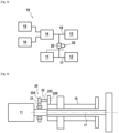
- FIG 3 schematically shows a free turbine turbomachine 10 according to one embodiment of the invention.
- the turbomachine 10 comprises an electric machine 11, a free turbine 12, a gas generator 13, an accessory box 14 and a fuel pump 15 and an oil pump 16.
- the free turbine 12 comprises a shaft 17 mechanically connected to the electric machine 11 permanently, that is to say during all phases of operation of the turbomachine 10, in particular the start-up phase and the electrical generation phase.
- This mechanical connection between the electric machine 11 and the shaft 17 can be carried out directly in such a way that the shaft 17 and the rotor of the electric machine 11 rotate at the same speed. It can also be carried out indirectly via a reducer in order to obtain different rotation speeds between the two members, in particular in the case where the nominal rotation speeds of the two members are intended to be different.
- the accessory box 14 includes a plurality of mechanical output couplers, a first mechanical output coupler being mechanically connected and coupled to the fuel pump 15 and a second mechanical output coupler being mechanically connected and connected to the oil pump 16. In other embodiments other accessories may be mechanically coupled to other mechanical output couplers of the accessory box 14.
- the gas generator 13 comprises a shaft 18 mechanically connected and coupled to the accessory box 14 permanently.
- the turbomachine 10 further comprises a single mechanical coupling means 20 configured to mechanically couple the shaft 18 of the gas generator 13 to the shaft 17 of the free turbine 12 in a first configuration and mechanically decouple the two shafts 17 and 18 in a second configuration.
- a possible embodiment of the mechanical coupling means 20 comprises a freewheel 21 and an intermediate pinion 22 mounted between the freewheel 21 and the shaft 18 of the gas generator 13.
- the freewheel 21 corresponds to the mechanical element of the mechanical coupling means 20 making it possible to couple or not the shaft 17 of the free turbine 12 to the shaft 18 of the gas generator 13.
- the intermediate pinion 22 comprises two wheels 22A and 22B of different diameters, mounted integrally on the same pinion shaft 22C, to have a transmission ratio different from 1 and thus have a rotation speed of the shaft 17 of the free turbine 12 different from the rotation speed of the shaft 18 of the gas generator 13.
- the means of mechanical coupling 20 would further comprise a transmission stage (such as an additional pinion) between the freewheel 21 and the intermediate pinion 22.
- the turbomachine 10 further comprises a control unit 30 of the electric machine 11 configured to place the electric machine 11 in a motor mode during a start-up phase of the turbomachine 10 and to place the electric machine 11 in a generator mode when the gas generator 13 becomes autonomous and therefore no longer needs to be driven by the electric machine 11.
- the detection of the autonomy of the gas generator by the control unit 30 can be done by detecting the instant when the speed of the shaft 18 of the gas generator 13 exceeds a speed threshold called the start-up phase exit speed threshold.
- this detection by the control unit 30 can be carried out by measuring the torque exerted by the shaft 17 of the free turbine on the output of the freewheel mechanically connected to the shaft 18 of the gas generator 13. If this torque is zero or becomes lower than a threshold close to zero, this means that the electrical machine 11 no longer drives the gas generator 13: the latter has become autonomous.
- this detection by the control unit 30 can be carried out by detecting the moment when the input and output of the freewheel start to rotate at different speeds. Indeed, when the gas generator 13 becomes autonomous, the output of the freewheel no longer rotates at the same speed as the input: it starts to rotate faster.
- the coupling means 20 is mechanically configured to mechanically couple the electric machine 11 to the free turbine 12 and to the gas generator 13 via the shafts 17 and 18 when starting the turbomachine 10. Indeed, the output rotation speed of the freewheel 21 (image of the rotation speed of the shaft 18) being zero or equal to the input speed of the freewheel 21 (image of the rotation speed of the shaft 17), the latter is connected, that is to say mechanically engaged, and allows the transfer of torque between the shaft 17 and the shaft 18.
- the coupling means 20 is mechanically configured to disconnect the two shafts 17 and 18 when the gas generator 13 becomes autonomous and reaches the start-up phase output speed threshold (the electric machine is no longer activated as a motor). Indeed, the electric machine 11 is no longer in mode "engine”, it will be driven by the free turbine 12 which will generate a speed differential at the terminals of the freewheel 21 leading to its disconnection, that is to say to its mechanical disengagement. Thus, the electric machine 11 can operate as an electric generator and produce electrical energy from the rotation of the shaft 17 of the free turbine 12 driven by the rotary movement of the free turbine 12 itself driven by the gas flow delivered by the gas generator 13.
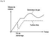
- FIG 5 is graphically represented the evolution, as a function of time and of the possible configuration of the turbogenerator, of the speed of the shaft 18 of the gas generator 13 in solid lines and, in dotted lines, of the speed of the shaft 17 of the free turbine 12 of the turbomachine 10 of the figure 3 .
- the architecture of the turbomachine 10 according to the invention allows a simultaneous increase in the speed of the gas generator 13 and the free turbine 12 until reaching the exit threshold of the start-up phase.
- the rotation speed of the electric machine 11 after the start-up phase can temporarily reduce the time that the power available at the free turbine can be sufficient to drive the assembly (free turbine and electric machine) at constant speed.
- the free turbine turbomachine according to the present invention thus makes it possible to optimize the mass, cost and reliability of the switching system and therefore of the turbomachine.
Landscapes
- Engineering & Computer Science (AREA)
- Chemical & Material Sciences (AREA)
- Combustion & Propulsion (AREA)
- Mechanical Engineering (AREA)
- General Engineering & Computer Science (AREA)
- Aviation & Aerospace Engineering (AREA)
- Control Of Eletrric Generators (AREA)
- Connection Of Motors, Electrical Generators, Mechanical Devices, And The Like (AREA)
Claims (10)
- Turbomaschine (1) vom Turbogeneratortyp mit Freilaufturbine, insbesondere für ein Luftfahrzeug mit Drehflügel, der elektrisch oder zu Zwecken der elektrischen Versorgung eines Flugzeugs angetrieben wird, wobei die Turbomaschine einen Gasgenerator (13) beinhaltet, der mit einer ersten mechanischen Welle (18), mindestens einer reversiblen elektrischen Maschine (11) und einer Freilaufturbine (12) ausgestattet ist, die mit einer zweiten mechanischen Welle (17) versehen und von einem Gasstrom drehbar angetrieben wird, der von dem Gasgenerator (13) erzeugt wird,dadurch gekennzeichnet, dass die zweite mechanische Welle (17) mechanisch an die mindestens eine elektrische Maschine (11) während allen Betriebsphasen der Turbomaschine (10) angeschlossen ist, unddie Turbomaschine (10) ferner ein einziges mechanisches Kopplungsmittel (20) umfasst, das dazu ausgestaltet ist, die erste mechanische Welle (18) mit der zweiten mechanischen Welle (17) mechanisch zu koppeln, wenn die elektrische Maschine (11) in dem Motormodus arbeitet, und die erste mechanische Welle (18) von der zweiten mechanischen Welle (17) mechanisch zu entkoppeln, wenn die elektrische Maschine (11) in dem Generatormodus arbeitet, wobei die elektrische Maschine (11) so bemessen ist, dass sie den Gasgenerator (13) und die Freilaufturbine (12) beim Start der Turbomaschine (10) antreibt.
- Turbomaschine (10) nach Anspruch 1, ferner umfassend eine Steuereinheit (30) der elektrischen Maschine (11), wobei die Steuereinheit (30) dazu ausgestaltet ist, die elektrische Maschine (11) beim Start der Turbomaschine (10) in den Motormodus zu setzen und die elektrische Maschine (11) in den Generatormodus zu setzen, wenn der Gasgenerator (13) autonom wird.
- Turbomaschine nach Anspruch 2, wobei die Steuereinheit (30) dazu ausgestaltet ist, zu erfassen, dass der Gasgenerator (13) autonom ist, wenn die Drehzahl der ersten mechanischen Welle (18) einen Schwellenwert der Abtriebsdrehzahl der Startphase überschreitet.
- Turbomaschine (10) nach einem der Ansprüche 1 bis 3, wobei das mechanische Kopplungsmittel (20) ein freies Rad (21) umfasst, das so ausgestaltet ist, dass sich die erste mechanische Welle (18), wenn sie mechanisch von der zweiten mechanischen Welle (17) entkoppelt wird, mit einer Drehzahl dreht, die größer als die Drehzahl der zweiten mechanischen Welle (17) ist.
- Turbomaschine (10) nach Anspruch 4, ferner umfassend mindestens ein Zwischenzahnrad (22), das ein Übersetzungsverhältnis aufweist, das ungleich der Zahl eins ist, wobei das mindestens eine Zwischenzahnrad (22) zwischen dem freien Rad (21) und der zweiten mechanischen Welle (17) und/oder zwischen dem freien Rad (21) und der ersten mechanischen Welle (18) montiert ist.
- Turbomaschine nach der Kombination der Ansprüche 2 und 4 oder der Kombination der Ansprüche 2, 4 und 5, wobei die Steuereinheit (30) dazu ausgestaltet ist, zu erfassen, dass der Gasgenerator (13) autonom ist, wenn das Drehmoment, das von der Welle (17) der Freilaufturbine (12) auf den Ausgang des freien Rades ausgeübt wird, einen Drehmoment-Schwellenwert überschreitet.
- Turbomaschine nach der Kombination der Ansprüche 2 und 4 oder der Kombination der Ansprüche 2, 4 und5, wobei die Steuereinheit (30) dazu ausgestaltet ist, zu erfassen, dass der Gasgenerator (13) autonom ist, wenn der Eingang und der Ausgang des freien Rades (21) sich mit verschiedenen Drehzahlen zu drehen beginnen.
- Turbomaschine (10) nach einem der Ansprüche 1 bis 7, ferner umfassend ein Anbaugerätegetriebe (14), das mechanisch mit der ersten mechanischen Welle (18) gekoppelt ist und mit welchem Anbaugeräte (15, 16) mechanisch gekoppelt sind.
- Turbomaschine (10) nach Anspruch 8, wobei die Turbomaschine (10) eine einzige elektrische Maschine (11) beinhaltet, wobei die elektrische Maschine (11) direkt von der mechanischen Welle (17) der Freilaufturbine (12) angetrieben wird.
- Turbomaschine (10) nach Anspruch 9, wobei die elektrische Maschine (11) eine Nenndrehzahl besitzt, die gleich oder annähernd jener der Freilaufturbine (12) ist.
Applications Claiming Priority (2)
| Application Number | Priority Date | Filing Date | Title |
|---|---|---|---|
| FR2011079A FR3115812B1 (fr) | 2020-10-29 | 2020-10-29 | Turbogénérateur à turbine libre comprenant une machine électrique réversible couplée à la turbine libre |
| PCT/FR2021/051875 WO2022090661A1 (fr) | 2020-10-29 | 2021-10-25 | Turbogenerateur a turbine libre comprenant une machine electrique reversible couplee a la turbine libre |
Publications (2)
| Publication Number | Publication Date |
|---|---|
| EP4237671A1 EP4237671A1 (de) | 2023-09-06 |
| EP4237671B1 true EP4237671B1 (de) | 2024-11-27 |
Family
ID=73699144
Family Applications (1)
| Application Number | Title | Priority Date | Filing Date |
|---|---|---|---|
| EP21810670.6A Active EP4237671B1 (de) | 2020-10-29 | 2021-10-25 | Freiturbinenturbogenerator mit einer reversiblen elektrischen maschine, die an die freiturbine gekoppelt ist |
Country Status (5)
| Country | Link |
|---|---|
| US (1) | US12467378B2 (de) |
| EP (1) | EP4237671B1 (de) |
| CN (1) | CN116490682B (de) |
| FR (1) | FR3115812B1 (de) |
| WO (1) | WO2022090661A1 (de) |
Families Citing this family (1)
| Publication number | Priority date | Publication date | Assignee | Title |
|---|---|---|---|---|
| FR3150183A1 (fr) | 2023-06-21 | 2024-12-27 | Safran Helicopter Engines | Turbomachine à hybridation électrique parallèle |
Family Cites Families (18)
| Publication number | Priority date | Publication date | Assignee | Title |
|---|---|---|---|---|
| BE597859R (fr) | 1960-09-09 | 1961-06-06 | Pfizer & Co C | Alcoyl-pénicillines alpha-substituées et leurs sels |
| US3660976A (en) * | 1970-04-20 | 1972-05-09 | Holley Carburetor Co | Turbine engine cycle temperature control system |
| US4044552A (en) * | 1976-07-19 | 1977-08-30 | General Motors Corporation | Gas turbine engine synchronous speed detector |
| US7513120B2 (en) * | 2005-04-08 | 2009-04-07 | United Technologies Corporation | Electrically coupled supercharger for a gas turbine engine |
| FR2929324B1 (fr) * | 2008-03-25 | 2012-10-12 | Turbomeca | Turbomoteur comportant une machine electrique reversible |
| DE102008031116B4 (de) * | 2008-05-29 | 2022-02-03 | Man Energy Solutions Se | Getriebeturbomaschine für einen Maschinenstrang, Maschinenstrang mit und Getriebe für Getriebeturbomaschine |
| GB0921323D0 (en) * | 2009-12-07 | 2010-01-20 | Rolls Royce Plc | An electrical machine |
| FR3019222B1 (fr) | 2014-03-27 | 2018-07-13 | Safran Helicopter Engines | Turbomoteur, helicoptere bimoteur equipe d'un tel turbomoteur et procede d'optimisation du regime de super-ralenti a puissance nulle d'un tel helicoptere bimoteur |
| FR3019220A1 (fr) * | 2014-03-27 | 2015-10-02 | Turbomeca | Procede de redemarrage alternatif d'un turbomoteur en veille d'un helicoptere et architecture multi-moteur permettant la mise en œuvre d'un tel procede |
| FR3019223B1 (fr) * | 2014-03-27 | 2016-03-18 | Turbomeca | Turbomoteur comprenant un dispositif de couplage mecanique commande, helicoptere equipe d'un tel turbomoteur et procede d'optimisation du regime de super-ralenti a puissance nulle d'un tel helicoptere |
| FR3019221B1 (fr) * | 2014-03-27 | 2018-10-12 | Safran Helicopter Engines | Dispositif hydraulique de demarrage d'urgence d'un turbomoteur, architecture d'un systeme propulsif d'un helicoptere multi-moteur equipe d'un tel dispositif et helicoptere correspondant |
| FR3019920B1 (fr) | 2014-04-14 | 2017-10-06 | Thales Sa | Equipement de substitution d'un equipement avionique d'affichage; systeme et module associes |
| FR3020838B1 (fr) * | 2014-05-07 | 2019-10-18 | Safran Aircraft Engines | Moteur a turbine a gaz a demarreur en prise avec un corps basse pression |
| US10408133B2 (en) * | 2014-10-03 | 2019-09-10 | Pratt & Whitney Canada Corp. | Accessory drive system for a gas turbine engine |
| US10815899B2 (en) * | 2016-11-15 | 2020-10-27 | Pratt & Whitney Canada Corp. | Gas turbine engine accessories arrangement |
| US10953995B2 (en) * | 2017-06-30 | 2021-03-23 | General Electric Company | Propulsion system for an aircraft |
| US10378452B1 (en) * | 2018-02-26 | 2019-08-13 | The Boeing Company | Hybrid turbine jet engines and methods of operating the same |
| FR3081150B1 (fr) * | 2018-05-18 | 2020-06-12 | Safran Helicopter Engines | Architecture de puissance d'un aeronef |
-
2020
- 2020-10-29 FR FR2011079A patent/FR3115812B1/fr active Active
-
2021
- 2021-10-25 EP EP21810670.6A patent/EP4237671B1/de active Active
- 2021-10-25 US US18/251,031 patent/US12467378B2/en active Active
- 2021-10-25 CN CN202180073215.4A patent/CN116490682B/zh active Active
- 2021-10-25 WO PCT/FR2021/051875 patent/WO2022090661A1/fr not_active Ceased
Also Published As
| Publication number | Publication date |
|---|---|
| CN116490682A (zh) | 2023-07-25 |
| CN116490682B (zh) | 2025-02-18 |
| EP4237671A1 (de) | 2023-09-06 |
| FR3115812A1 (fr) | 2022-05-06 |
| FR3115812B1 (fr) | 2023-09-08 |
| US20230323787A1 (en) | 2023-10-12 |
| US12467378B2 (en) | 2025-11-11 |
| WO2022090661A1 (fr) | 2022-05-05 |
Similar Documents
| Publication | Publication Date | Title |
|---|---|---|
| EP2281109B1 (de) | Turbomotor mit einer reversiblen elektrischen maschine | |
| EP1985823B1 (de) | Vorrichtung zur Erzeugung von elektrischer Energie in einer Zweiwellen-Fluggasturbine | |
| EP4244474B1 (de) | Turbomaschine mit freier turbine mit elektrischen maschinen zur unterstützung eines gasgenerators und einer freien turbine | |
| EP3464855A1 (de) | Flugzeugturbinentriebwerk mit epizyklischem untersetzungsgetriebe mit variablem übersetzungsverhältnis | |
| WO2021074537A1 (fr) | Système propulsif pour un hélicoptère | |
| EP4334210B1 (de) | Verbessertes getriebe für hybridflugzeuge | |
| EP4343133A1 (de) | Kompaktes zubehörgehäuse mit integrierter elektrischer maschine | |
| EP4237671B1 (de) | Freiturbinenturbogenerator mit einer reversiblen elektrischen maschine, die an die freiturbine gekoppelt ist | |
| EP4562285A1 (de) | Verbesserte antriebsanordnung für ein hybridflugzeug mit mehreren triebwerken | |
| EP4237666B1 (de) | Turbomaschine mit freier turbine und mit einer durch die freie turbine angetriebenen vorrichtung | |
| EP4493807A1 (de) | Verbesserte turbomaschine für ein hybridflugzeug | |
| EP4320341B1 (de) | Turbomaschine mit freier turbine und mit einer durch die freie turbine angetriebenen vorrichtung | |
| WO2023166256A1 (fr) | Ensemble propulsif ameliore pour aeronef hybride multi moteurs | |
| WO2024261430A1 (fr) | Turbomachine à hybridation électrique parallèle | |
| FR3138411A1 (fr) | Ensemble propulsif amélioré pour aéronef hybridé multi moteurs | |
| WO2024161082A1 (fr) | Assemblage pour ensemble propulsif d'aeronef avec accouplement debrayable de deux arbres par un manchon d'accouplement a actionnement par fluide pressurise | |
| FR3142460A1 (fr) | Turbopropulseur hybride amélioré pour aéronef |
Legal Events
| Date | Code | Title | Description |
|---|---|---|---|
| STAA | Information on the status of an ep patent application or granted ep patent |
Free format text: STATUS: UNKNOWN |
|
| STAA | Information on the status of an ep patent application or granted ep patent |
Free format text: STATUS: THE INTERNATIONAL PUBLICATION HAS BEEN MADE |
|
| PUAI | Public reference made under article 153(3) epc to a published international application that has entered the european phase |
Free format text: ORIGINAL CODE: 0009012 |
|
| STAA | Information on the status of an ep patent application or granted ep patent |
Free format text: STATUS: REQUEST FOR EXAMINATION WAS MADE |
|
| 17P | Request for examination filed |
Effective date: 20230529 |
|
| AK | Designated contracting states |
Kind code of ref document: A1 Designated state(s): AL AT BE BG CH CY CZ DE DK EE ES FI FR GB GR HR HU IE IS IT LI LT LU LV MC MK MT NL NO PL PT RO RS SE SI SK SM TR |
|
| DAV | Request for validation of the european patent (deleted) | ||
| DAX | Request for extension of the european patent (deleted) | ||
| GRAP | Despatch of communication of intention to grant a patent |
Free format text: ORIGINAL CODE: EPIDOSNIGR1 |
|
| STAA | Information on the status of an ep patent application or granted ep patent |
Free format text: STATUS: GRANT OF PATENT IS INTENDED |
|
| INTG | Intention to grant announced |
Effective date: 20240701 |
|
| GRAS | Grant fee paid |
Free format text: ORIGINAL CODE: EPIDOSNIGR3 |
|
| GRAA | (expected) grant |
Free format text: ORIGINAL CODE: 0009210 |
|
| STAA | Information on the status of an ep patent application or granted ep patent |
Free format text: STATUS: THE PATENT HAS BEEN GRANTED |
|
| AK | Designated contracting states |
Kind code of ref document: B1 Designated state(s): AL AT BE BG CH CY CZ DE DK EE ES FI FR GB GR HR HU IE IS IT LI LT LU LV MC MK MT NL NO PL PT RO RS SE SI SK SM TR |
|
| REG | Reference to a national code |
Ref country code: GB Ref legal event code: FG4D Free format text: NOT ENGLISH |
|
| REG | Reference to a national code |
Ref country code: CH Ref legal event code: EP |
|
| REG | Reference to a national code |
Ref country code: IE Ref legal event code: FG4D Free format text: LANGUAGE OF EP DOCUMENT: FRENCH |
|
| REG | Reference to a national code |
Ref country code: DE Ref legal event code: R096 Ref document number: 602021022568 Country of ref document: DE |
|
| REG | Reference to a national code |
Ref country code: LT Ref legal event code: MG9D |
|
| REG | Reference to a national code |
Ref country code: NL Ref legal event code: MP Effective date: 20241127 |
|
| PG25 | Lapsed in a contracting state [announced via postgrant information from national office to epo] |
Ref country code: IS Free format text: LAPSE BECAUSE OF FAILURE TO SUBMIT A TRANSLATION OF THE DESCRIPTION OR TO PAY THE FEE WITHIN THE PRESCRIBED TIME-LIMIT Effective date: 20250327 Ref country code: PT Free format text: LAPSE BECAUSE OF FAILURE TO SUBMIT A TRANSLATION OF THE DESCRIPTION OR TO PAY THE FEE WITHIN THE PRESCRIBED TIME-LIMIT Effective date: 20250327 Ref country code: HR Free format text: LAPSE BECAUSE OF FAILURE TO SUBMIT A TRANSLATION OF THE DESCRIPTION OR TO PAY THE FEE WITHIN THE PRESCRIBED TIME-LIMIT Effective date: 20241127 |
|
| PG25 | Lapsed in a contracting state [announced via postgrant information from national office to epo] |
Ref country code: FI Free format text: LAPSE BECAUSE OF FAILURE TO SUBMIT A TRANSLATION OF THE DESCRIPTION OR TO PAY THE FEE WITHIN THE PRESCRIBED TIME-LIMIT Effective date: 20241127 Ref country code: NL Free format text: LAPSE BECAUSE OF FAILURE TO SUBMIT A TRANSLATION OF THE DESCRIPTION OR TO PAY THE FEE WITHIN THE PRESCRIBED TIME-LIMIT Effective date: 20241127 |
|
| REG | Reference to a national code |
Ref country code: AT Ref legal event code: MK05 Ref document number: 1745908 Country of ref document: AT Kind code of ref document: T Effective date: 20241127 |
|
| PG25 | Lapsed in a contracting state [announced via postgrant information from national office to epo] |
Ref country code: BG Free format text: LAPSE BECAUSE OF FAILURE TO SUBMIT A TRANSLATION OF THE DESCRIPTION OR TO PAY THE FEE WITHIN THE PRESCRIBED TIME-LIMIT Effective date: 20241127 |
|
| PG25 | Lapsed in a contracting state [announced via postgrant information from national office to epo] |
Ref country code: ES Free format text: LAPSE BECAUSE OF FAILURE TO SUBMIT A TRANSLATION OF THE DESCRIPTION OR TO PAY THE FEE WITHIN THE PRESCRIBED TIME-LIMIT Effective date: 20241127 |
|
| PG25 | Lapsed in a contracting state [announced via postgrant information from national office to epo] |
Ref country code: NO Free format text: LAPSE BECAUSE OF FAILURE TO SUBMIT A TRANSLATION OF THE DESCRIPTION OR TO PAY THE FEE WITHIN THE PRESCRIBED TIME-LIMIT Effective date: 20250227 |
|
| PG25 | Lapsed in a contracting state [announced via postgrant information from national office to epo] |
Ref country code: LV Free format text: LAPSE BECAUSE OF FAILURE TO SUBMIT A TRANSLATION OF THE DESCRIPTION OR TO PAY THE FEE WITHIN THE PRESCRIBED TIME-LIMIT Effective date: 20241127 Ref country code: AT Free format text: LAPSE BECAUSE OF FAILURE TO SUBMIT A TRANSLATION OF THE DESCRIPTION OR TO PAY THE FEE WITHIN THE PRESCRIBED TIME-LIMIT Effective date: 20241127 Ref country code: GR Free format text: LAPSE BECAUSE OF FAILURE TO SUBMIT A TRANSLATION OF THE DESCRIPTION OR TO PAY THE FEE WITHIN THE PRESCRIBED TIME-LIMIT Effective date: 20250228 |
|
| PG25 | Lapsed in a contracting state [announced via postgrant information from national office to epo] |
Ref country code: PL Free format text: LAPSE BECAUSE OF FAILURE TO SUBMIT A TRANSLATION OF THE DESCRIPTION OR TO PAY THE FEE WITHIN THE PRESCRIBED TIME-LIMIT Effective date: 20241127 |
|
| PG25 | Lapsed in a contracting state [announced via postgrant information from national office to epo] |
Ref country code: RS Free format text: LAPSE BECAUSE OF FAILURE TO SUBMIT A TRANSLATION OF THE DESCRIPTION OR TO PAY THE FEE WITHIN THE PRESCRIBED TIME-LIMIT Effective date: 20250227 |
|
| PG25 | Lapsed in a contracting state [announced via postgrant information from national office to epo] |
Ref country code: SM Free format text: LAPSE BECAUSE OF FAILURE TO SUBMIT A TRANSLATION OF THE DESCRIPTION OR TO PAY THE FEE WITHIN THE PRESCRIBED TIME-LIMIT Effective date: 20241127 |
|
| PG25 | Lapsed in a contracting state [announced via postgrant information from national office to epo] |
Ref country code: DK Free format text: LAPSE BECAUSE OF FAILURE TO SUBMIT A TRANSLATION OF THE DESCRIPTION OR TO PAY THE FEE WITHIN THE PRESCRIBED TIME-LIMIT Effective date: 20241127 |
|
| PG25 | Lapsed in a contracting state [announced via postgrant information from national office to epo] |
Ref country code: EE Free format text: LAPSE BECAUSE OF FAILURE TO SUBMIT A TRANSLATION OF THE DESCRIPTION OR TO PAY THE FEE WITHIN THE PRESCRIBED TIME-LIMIT Effective date: 20241127 |
|
| PG25 | Lapsed in a contracting state [announced via postgrant information from national office to epo] |
Ref country code: RO Free format text: LAPSE BECAUSE OF FAILURE TO SUBMIT A TRANSLATION OF THE DESCRIPTION OR TO PAY THE FEE WITHIN THE PRESCRIBED TIME-LIMIT Effective date: 20241127 |
|
| PG25 | Lapsed in a contracting state [announced via postgrant information from national office to epo] |
Ref country code: SK Free format text: LAPSE BECAUSE OF FAILURE TO SUBMIT A TRANSLATION OF THE DESCRIPTION OR TO PAY THE FEE WITHIN THE PRESCRIBED TIME-LIMIT Effective date: 20241127 |
|
| PG25 | Lapsed in a contracting state [announced via postgrant information from national office to epo] |
Ref country code: CZ Free format text: LAPSE BECAUSE OF FAILURE TO SUBMIT A TRANSLATION OF THE DESCRIPTION OR TO PAY THE FEE WITHIN THE PRESCRIBED TIME-LIMIT Effective date: 20241127 |
|
| REG | Reference to a national code |
Ref country code: DE Ref legal event code: R097 Ref document number: 602021022568 Country of ref document: DE |
|
| PG25 | Lapsed in a contracting state [announced via postgrant information from national office to epo] |
Ref country code: SE Free format text: LAPSE BECAUSE OF FAILURE TO SUBMIT A TRANSLATION OF THE DESCRIPTION OR TO PAY THE FEE WITHIN THE PRESCRIBED TIME-LIMIT Effective date: 20241127 |
|
| PLBE | No opposition filed within time limit |
Free format text: ORIGINAL CODE: 0009261 |
|
| STAA | Information on the status of an ep patent application or granted ep patent |
Free format text: STATUS: NO OPPOSITION FILED WITHIN TIME LIMIT |
|
| 26N | No opposition filed |
Effective date: 20250828 |
|
| PGFP | Annual fee paid to national office [announced via postgrant information from national office to epo] |
Ref country code: DE Payment date: 20251020 Year of fee payment: 5 |
|
| PGFP | Annual fee paid to national office [announced via postgrant information from national office to epo] |
Ref country code: GB Payment date: 20251029 Year of fee payment: 5 |
|
| PGFP | Annual fee paid to national office [announced via postgrant information from national office to epo] |
Ref country code: IT Payment date: 20251031 Year of fee payment: 5 |
|
| PGFP | Annual fee paid to national office [announced via postgrant information from national office to epo] |
Ref country code: FR Payment date: 20251024 Year of fee payment: 5 |