EP4237666B1 - Turbomaschine mit freier turbine und mit einer durch die freie turbine angetriebenen vorrichtung - Google Patents
Turbomaschine mit freier turbine und mit einer durch die freie turbine angetriebenen vorrichtung Download PDFInfo
- Publication number
- EP4237666B1 EP4237666B1 EP21807195.9A EP21807195A EP4237666B1 EP 4237666 B1 EP4237666 B1 EP 4237666B1 EP 21807195 A EP21807195 A EP 21807195A EP 4237666 B1 EP4237666 B1 EP 4237666B1
- Authority
- EP
- European Patent Office
- Prior art keywords
- turbomachine
- mechanical
- free turbine
- gas generator
- shaft
- Prior art date
- Legal status (The legal status is an assumption and is not a legal conclusion. Google has not performed a legal analysis and makes no representation as to the accuracy of the status listed.)
- Active
Links
Images

Classifications
-
- F—MECHANICAL ENGINEERING; LIGHTING; HEATING; WEAPONS; BLASTING
- F02—COMBUSTION ENGINES; HOT-GAS OR COMBUSTION-PRODUCT ENGINE PLANTS
- F02C—GAS-TURBINE PLANTS; AIR INTAKES FOR JET-PROPULSION PLANTS; CONTROLLING FUEL SUPPLY IN AIR-BREATHING JET-PROPULSION PLANTS
- F02C3/00—Gas-turbine plants characterised by the use of combustion products as the working fluid
- F02C3/04—Gas-turbine plants characterised by the use of combustion products as the working fluid having a turbine driving a compressor
- F02C3/10—Gas-turbine plants characterised by the use of combustion products as the working fluid having a turbine driving a compressor with another turbine driving an output shaft but not driving the compressor
- F02C3/103—Gas-turbine plants characterised by the use of combustion products as the working fluid having a turbine driving a compressor with another turbine driving an output shaft but not driving the compressor the compressor being of the centrifugal type
-
- F—MECHANICAL ENGINEERING; LIGHTING; HEATING; WEAPONS; BLASTING
- F01—MACHINES OR ENGINES IN GENERAL; ENGINE PLANTS IN GENERAL; STEAM ENGINES
- F01D—NON-POSITIVE DISPLACEMENT MACHINES OR ENGINES, e.g. STEAM TURBINES
- F01D15/00—Adaptations of machines or engines for special use; Combinations of engines with devices driven thereby
- F01D15/10—Adaptations for driving, or combinations with, electric generators
-
- F—MECHANICAL ENGINEERING; LIGHTING; HEATING; WEAPONS; BLASTING
- F02—COMBUSTION ENGINES; HOT-GAS OR COMBUSTION-PRODUCT ENGINE PLANTS
- F02C—GAS-TURBINE PLANTS; AIR INTAKES FOR JET-PROPULSION PLANTS; CONTROLLING FUEL SUPPLY IN AIR-BREATHING JET-PROPULSION PLANTS
- F02C3/00—Gas-turbine plants characterised by the use of combustion products as the working fluid
- F02C3/04—Gas-turbine plants characterised by the use of combustion products as the working fluid having a turbine driving a compressor
- F02C3/107—Gas-turbine plants characterised by the use of combustion products as the working fluid having a turbine driving a compressor with two or more rotors connected by power transmission
-
- F—MECHANICAL ENGINEERING; LIGHTING; HEATING; WEAPONS; BLASTING
- F02—COMBUSTION ENGINES; HOT-GAS OR COMBUSTION-PRODUCT ENGINE PLANTS
- F02C—GAS-TURBINE PLANTS; AIR INTAKES FOR JET-PROPULSION PLANTS; CONTROLLING FUEL SUPPLY IN AIR-BREATHING JET-PROPULSION PLANTS
- F02C7/00—Features, components parts, details or accessories, not provided for in, or of interest apart form groups F02C1/00 - F02C6/00; Air intakes for jet-propulsion plants
- F02C7/26—Starting; Ignition
- F02C7/268—Starting drives for the rotor, acting directly on the rotor of the gas turbine to be started
- F02C7/275—Mechanical drives
-
- F—MECHANICAL ENGINEERING; LIGHTING; HEATING; WEAPONS; BLASTING
- F02—COMBUSTION ENGINES; HOT-GAS OR COMBUSTION-PRODUCT ENGINE PLANTS
- F02C—GAS-TURBINE PLANTS; AIR INTAKES FOR JET-PROPULSION PLANTS; CONTROLLING FUEL SUPPLY IN AIR-BREATHING JET-PROPULSION PLANTS
- F02C7/00—Features, components parts, details or accessories, not provided for in, or of interest apart form groups F02C1/00 - F02C6/00; Air intakes for jet-propulsion plants
- F02C7/32—Arrangement, mounting, or driving, of auxiliaries
-
- F—MECHANICAL ENGINEERING; LIGHTING; HEATING; WEAPONS; BLASTING
- F05—INDEXING SCHEMES RELATING TO ENGINES OR PUMPS IN VARIOUS SUBCLASSES OF CLASSES F01-F04
- F05D—INDEXING SCHEME FOR ASPECTS RELATING TO NON-POSITIVE-DISPLACEMENT MACHINES OR ENGINES, GAS-TURBINES OR JET-PROPULSION PLANTS
- F05D2220/00—Application
- F05D2220/70—Application in combination with
- F05D2220/76—Application in combination with an electrical generator
-
- F—MECHANICAL ENGINEERING; LIGHTING; HEATING; WEAPONS; BLASTING
- F05—INDEXING SCHEMES RELATING TO ENGINES OR PUMPS IN VARIOUS SUBCLASSES OF CLASSES F01-F04
- F05D—INDEXING SCHEME FOR ASPECTS RELATING TO NON-POSITIVE-DISPLACEMENT MACHINES OR ENGINES, GAS-TURBINES OR JET-PROPULSION PLANTS
- F05D2260/00—Function
- F05D2260/85—Starting
Definitions
- the present invention relates to the general field of aeronautical turbomachines with free turbine, in particular for turbogenerators, and more particularly to an architecture of such a turbomachine allowing the driving of equipment via the free turbine without compromising the operation of the equipment when starting the turbomachine.
- a free turbine helicopter engine generally comprises a gas generator and a free turbine driven in rotation by the gas flow generated by the gas generator, as well as a reversible electrical machine which can be coupled to the gas generator in particular to set the gas generator in rotation during a start-up phase of the engine.
- the gas generator comprises at least one compressor and one turbine coupled in rotation.
- the operating principle is as follows: the fresh air entering the turboshaft engine is compressed due to the rotation of the compressor before being sent to a combustion chamber where it is mixed with a fuel. The gases burnt during combustion are then evacuated at high speed.
- the gas generator turbine does not absorb all the kinetic energy of the burnt gases and the excess kinetic energy corresponds to the gas flow generated by the gas generator. The latter therefore supplies kinetic energy to the free turbine so that a second expansion occurs in the free turbine which transforms this kinetic energy into mechanical energy in order to drive a receiving organ, such as the rotor of the helicopter.
- an electric machine 1 in a motor operation drives the mechanical shaft 2 of the gas generator 3, until the rotation of the latter is maintained by the combustion of fuel.
- the rotational drive of the shaft of the gas generator by the reversible electric machine operating in motor mode during the starting phase also makes it possible to drive equipment, not shown in this figure and which can be driven by the shaft 2 via an accessory box. This makes it possible to supply the turbomachine with fuel and oil and to circulate air in the compressor 4 and therefore to bring compressed air into the combustion chamber 5 in order to initiate combustion.
- This combustion then produces the gas flow enabling the turbine 6 of the gas turbine 3 to be driven in rotation, after which the compressor 4 and the equipment are driven in rotation by the turbine 6 without the aid of the electric machine, which means that the gas generator 3 operates autonomously, reflecting the end of the start-up phase of the turboshaft engine.
- a second electric machine 7 engaged on the shaft 8 of the free turbine 9 makes it possible to meet the need for high power generation.
- equipment such as the fuel pump, and the oil pump are mechanically connected to the shaft 2 of the gas generator 3 via the accessory box.
- Equipment that requires mechanical energy to be driven in rotation for example pumps, are also called accessories and are generally mounted on an accessory box which includes at least one gear train to adapt the rotation speeds of the accessories.
- the start-up phase it is known to use the reversible electric machine in a generator operating mode to produce non-propulsive electrical energy (28V network for example) to supply electricity to the electrical equipment.
- the electric machine 1 generates electrical energy by taking mechanical power from the shaft 2 of the gas generator 3, the rotational kinetic energy taken from the gas generator being transformed into electrical energy by said machine.
- This electric machine 1 may be non-reversible and consist of a simple starter, such as a choke, if the need for electrical generation does not exist.
- the mechanical draw on the gas generator shaft used to generate electrical power by the reversible electric machine 1 in a generator operating mode affects the performance of the gas generator.
- a known architecture for starting a free turbine turbogenerator without the addition of a specific starter is disclosed in the document FR 2 929 324
- This technical solution makes it possible to reduce the total mass and cost and to increase the reliability of the turbogenerator compared to a turbomachine comprising two electric machines as on the figure 1 .
- the technical solution described in this document consists of a switching system using two freewheels to start the gas generator of a free turbine engine and then to generate non-propulsive electrical energy by taking mechanical energy from the free turbine shaft. The equipment remains driven via the gas generator and the accessory box.
- This solution makes it possible in particular to improve the transient performance of the gas generator, by avoiding the disadvantages of drawing kinetic energy from the gas generator, and in particular the problem of the displacement of the engine operating line in the compressor field due to the variation, during flight, of the mechanical power drawn by the electric machine.
- This architecture with two freewheels is advantageous in the context of a helicopter turbomachine in order not to drive the main rotor via the electric machine during the start-up phase.
- the free turbine of the turbomachine being mechanically connected to the main rotor, a coupling between the shaft of the free turbine and the main rotor which could not be decoupled during the start-up phase would require oversizing at least the energy storage system so that the electric machine has enough energy to be able to drive the entire drive train (including the main rotor) in rotation.
- the present invention proposes a free turbine turbomachine driving one or more electric machines of sufficient power equipped with a simplified switching system making it possible to optimize mass, cost and reliability.
- a turbomachine comprising a gas generator provided with a first mechanical shaft, at least one reversible electrical machine, a free turbine provided with a second mechanical shaft and driven in rotation by a gas flow generated by the gas generator, an accessory box, and at least one accessory coupled to the accessory box.
- the electric machine is mechanically coupled to said second mechanical shaft via the accessory box during all operating phases of the turbomachine
- the turbomachine further comprises a single mechanical coupling means configured to mechanically coupling said first mechanical shaft to the accessory box in a first configuration and mechanically decoupling said first mechanical shaft from the accessory box in a second configuration, the electric machine being sized to drive the gas generator, the free turbine and said at least one accessory when starting the turbomachine.
- the turbomachine according to the invention comprising an electric machine and a single freewheel thus makes it possible to pool the function of starting the gas generator and generating high-power electricity on the electric machine, and allows the free turbine to drive the accessories once the turbomachine has started. Indeed, it makes it possible to initiate the rotation of the accessories, the free turbine and that of the gas generator until the gas generator can operate autonomously, then to continue to drive the free turbine and the accessories until the free turbine can also operate autonomously. Once the free turbine is rotating autonomously, the electric machine can operate in generator mode and thus provide electrical power to other elements.
- the architecture of the turbomachine according to the invention thus makes it possible to have only one mechanical coupling means, such as a freewheel, which makes it possible to simplify the switching system and in particular, compared to known solutions, to reduce the mass and the cost.
- the electric machine(s) are sized to generate high levels of electric power (for example for propulsive energy), and can, when used in engine mode, easily deliver the torque necessary to drive the gas generator, the free turbine and the equipment during the start-up phase. Indeed, in such applications, the inertia of the free turbine shaft line is low because it is not coupled to a helicopter rotor for example (power chain and rotors of the electric machines only).
- the architecture according to the invention allows, in the event of a breakage of the free turbine shaft during operation, to directly impact the drive of the accessories (including the fuel pump) having the direct effect of switching off instantly the engine and therefore limit the overspeed of the free turbine.
- This architecture has the effect of protecting the free turbine from overspeed.
- the turbomachine may further comprise a control unit for the electric machine, the control unit being configured to place the electric machine in motor mode when starting the turbomachine, and to place the electric machine in generator mode when the speed of the first mechanical shaft exceeds a start-up phase output speed threshold.
- the electric machine can be configured to operate in engine mode from the start-up phase of the turbomachine and until one of the operating parameters of the second mechanical shaft or of said electric machine has exceeded a threshold from which the free turbine is said to be autonomous.
- the value of the operating parameter corresponding to the threshold from which the free turbine is autonomous is preferably greater than the value that said operating parameter has when the first shaft reaches the start-up phase output speed threshold.
- the threshold from which the free turbine is autonomous occurs after the moment when the gas generator has become autonomous.
- the electric machine is configured to operate in generator mode once said parameter of the second mechanical shaft or of the electric machine has exceeded the threshold from which the free turbine is autonomous.
- the start-up phase and the transition phase can be achieved via torque control or speed control.
- An operating parameter of the second mechanical shaft can be its speed or its mechanical torque.
- the control unit drives the electric machine while interacting with the turbomachine computer.
- Driving in speed before ignition detection allows you to stay within the preferential ignition window, i.e. the speed range in which the chances of successful ignition are highest.
- Speed control during the transition phase i.e. after decoupling the gas generator and before switching to generator mode of the electric machine, makes it possible to maintain a constant speed during the transition by compensating for the variation in torque on the accessories coupled to the accessory box.
- the torque supplied by the electric machine during the transition phase will reduce until it is zero as the torque delivered by the free turbine increases.
- the mechanical coupling means may comprise a freewheel.
- the coupling means may be included in a housing of the accessory box.
- the accessory box gears thus make it possible to adapt the speeds for equipment, such as a fuel pump or an oil pump, mechanically coupled to the first mechanical shaft, i.e. to the gas generator, but also to ensure, outside the start-up phase, that the input speed of the freewheel, i.e. on the mechanical terminal of the freewheel coupled to the second mechanical shaft, is always lower than the output speed of the freewheel, i.e. on the mechanical terminal of the freewheel coupled to the first mechanical shaft. And this over the entire nominal operating range of the gas generator and the free turbine, therefore outside the start-up phase.
- equipment such as a fuel pump or an oil pump
- the accessory box can be configured to change the speed ratio between the free turbine and the gas generator when the mechanical coupling means is in its first configuration.
- the accessory box can be arranged and connectable between the mechanical coupling means and the second mechanical shaft.
- the accessory box allows the transmission ratio to be modified by taking into account the sign of the ratio, i.e. by offering the possibility of ensuring counter-rotation of the two shafts, while ensuring the integration of secondary functions.
- This configuration improves the efficiency of ventilation after engine shutdown, as both shafts are driven simultaneously.
- the turbomachine may further comprise an additional accessory box connected to the first shaft for coupling additional accessories directly to the gas generator permanently.
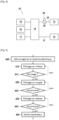
- FIG 3 schematically shows a free turbine turbomachine 10 according to one embodiment of the invention.
- the turbomachine 10 comprises an electric machine 11, a free turbine 12, a gas generator 13, an accessory box 14, a fuel pump 15 and an oil pump 16.
- the free turbine 12 comprises a shaft 17 directly mechanically connected to the accessory box 14 permanently.
- the accessory box 14 is mechanically coupled to the electric machine 11.
- the kinematic chain between the electric machine 11 and the free turbine 12 does not comprise any uncoupling device, which thus makes it possible to have the turbine 12 coupled to the electric machine 11 during all the operating phases of the turbomachine 10, in particular during the start-up phase and the electrical generation phase.
- the accessory box 14 is also mechanically coupled to the fuel pump 15, on the one hand, and to the oil pump 16, on the other hand. In other embodiments other accessories may be mechanically coupled to the accessory box 14.
- the gas generator 13 includes a shaft 18 connected and mechanically coupled to the accessory box 14 via a single mechanical coupling means 20.
- the single mechanical coupling means 20 is configured to mechanically coupling the shaft 18 of the gas generator 13 to the accessory box 14 in a first configuration, and mechanically decoupling it from the accessory box 14 in a second configuration in order in particular to decouple the shaft 18 of the gas generator from the shaft 17 and the electric machine 11.
- the shaft 18 of the gas generator 13 is thus selectively coupled to the electric machine 11 via the accessory box 14.
- the mechanical coupling means 20 comprises a freewheel.
- the turbomachine 10 further comprises a control unit 30 of the electric machine 11 configured to place the electric machine 11 in engine mode during a start-up phase of the turbomachine 10 and to place the electric machine 11 in a generator mode when it is detected that the free turbine can operate autonomously.
- the coupling means 20 is mechanically configured to have the electric machine 11 mechanically coupled to the gas generator 13 via the shaft 18 when starting the turbomachine 10.
- the coupling means 20 is mechanically configured to decouple the gas generator from the electrical machine 11 when the gas generator 13 reaches a start-up phase output speed threshold.
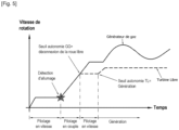
- FIG 5 is graphically represented the evolution, as a function of time and of the possible configuration of the turbogenerator, of the speed of the shaft 18 of the gas generator 13 in solid lines and, in dotted lines, of the speed of the shaft 17 of the free turbine 12 of the turbomachine 10 of the figure 3 when starting it using the method of the figure 4 .
- the method for starting the turbomachine 10 comprises a first step 405 in which the electric machine 11 is placed in engine mode and started to begin rotating the shafts 17 and 18 of the free turbine 12 and the gas generator 13 via the accessory box 14. Indeed, when the accessory box 14 is rotated by the electric machine 11, the mechanical coupling means 20, which may be a freewheel, automatically transmits the torque required for rotating the gas generator 13.
- the electric machine 11 is controlled for example by the control unit 30, in a second step 410, as a function of the rotation speed of its mechanical shaft coupled to the accessory box 14, so that the rotation speed of the shaft 17 of the gas generator 13 is maintained within the ignition window, that is to say in a speed range specified to maximize the chances of successful ignition of the combustion chamber of the gas generator.
- the control unit 30 can comprise an electronic processing unit such as a calculator and receive information on the speed of the shaft of the electric machine 11 or of the shaft 17 of the gas generator 13, these two speeds being proportional to each other with a reduction factor specific to the gear train of the accessory box 14.
- a third step 415 it is checked whether the combustion chamber of the gas generator 13 is ignited. As long as the ignition of the gas generator 13 is not detected, the speed control of the electric machine 11 is maintained.
- step 415 the electric machine 11 is controlled, in a fourth step 420, in torque following a predefined curve of the torque as a function of the rotation speed of the electric machine 11.
- a fifth step 425 the rotational speed of the shaft 18 of the gas generator is compared with an autonomous operating threshold of the gas generator.
- the autonomous operating threshold of the gas generator 13 is defined for example with respect to a rotational speed value from which the gas generator can operate autonomously. As long as the rotational speed of the shaft 18 of the gas generator 13 has not reached a value corresponding to the autonomous operating threshold of the gas generator 13, the control of the electric machine 11 continues to be carried out in torque in the fourth step 420.
- a sixth step 430 the electric machine 11 is controlled in speed according to a threshold allowing the correct operation of accessories such as the fuel pump 15 and the oil pump 16, and limiting the electrical power drawn from the network.
- a seventh step 435 for example, the level of torque delivered by the electric machine and/or its rotation speed is compared to a corresponding threshold from which the free turbine can operate autonomously, in other words from which the flow delivered by the gas generator 13 is sufficient to maintain the rotation of the free turbine 12 or to accelerate it.
- a corresponding threshold from which the free turbine can operate autonomously, in other words from which the flow delivered by the gas generator 13 is sufficient to maintain the rotation of the free turbine 12 or to accelerate it.
- an eighth step 440 the electric machine 11 changes operating mode.
- the electric machine 11 switches from motor mode to generator mode.
- the electric machine 11 can operate as an electric generator and produce electrical energy from the rotation of the shaft 17 of the free turbine driven by the rotary movement of the free turbine 12 itself driven by the gas flow delivered by the gas generator 13.
- the free turbine turbomachine according to the present invention thus makes it possible to optimize the mass, cost and reliability of the switching system and therefore of the turbomachine.
Landscapes
- Engineering & Computer Science (AREA)
- Chemical & Material Sciences (AREA)
- Combustion & Propulsion (AREA)
- Mechanical Engineering (AREA)
- General Engineering & Computer Science (AREA)
- Control Of Eletrric Generators (AREA)
- Connection Of Motors, Electrical Generators, Mechanical Devices, And The Like (AREA)
- Control Of Turbines (AREA)
Claims (9)
- Turbomaschine (10), die einen Gasgenerator (13), der mit einer ersten mechanischen Welle (18) ausgestattet ist, mindestens eine reversible elektrische Maschine (11), eine freie Turbine (12), die mit einer zweiten mechanischen Welle (17) versehen ist und durch einen Gasstrom, der durch den Gasgenerator (13) erzeugt wird, drehangetrieben wird, einen Zubehörkasten (14) und mindestens ein Zubehör (15, 16) beinhaltet, das an den Zubehörkasten (14) gekoppelt ist,
dadurch gekennzeichnet, dass die mindestens eine reversible elektrische Maschine (11) während aller Betriebsphasen der Turbomaschine (10) über den Zubehörkasten (14) mechanisch an die zweite mechanische Welle (17) gekoppelt ist, und die Turbomaschine (10) ferner ein einzelnes mechanisches Kopplungsmittel (20) umfasst, das dazu ausgestaltet ist, in einer ersten Ausgestaltung die erste mechanische Welle (18) mechanisch an den Zubehörkasten (14) zu koppeln und in einer zweiten Ausgestaltung die erste mechanische Welle (18) mechanisch von dem Zubehörkasten (14) zu entkoppeln, wobei die reversible elektrische Maschine (11) so dimensioniert ist, dass sie den Gasgenerator (13) sowie das mindestens eine Zubehör (15, 16) und die freie Turbine (12) während des Starts der Turbomaschine (10) antreibt. - Turbomaschine (10) nach Anspruch 1, ferner umfassend eine Steuereinheit (30) der mindestens einen reversiblen elektrischen Maschine (11), wobei die Steuereinheit (30) dazu ausgestaltet ist, die elektrische Maschine (11) während des Starts der Turbomaschine (10) in den Motormodus zu versetzen und die elektrische Maschine (11) in den Generatormodus zu versetzen, wenn erkannt wird, dass die freie Turbine auf autonome Weise arbeiten kann.
- Turbomaschine (10) nach Anspruch 2, wobei die reversible elektrische Maschine (11) dazu ausgestaltet ist, ab der Startphase der Turbomaschine (10) und bis einer der mechanischen Parameter der zweiten mechanischen Welle (17) oder der elektrischen Maschine (11) einen Schwellenwert überschritten hat, ab dem die freie Turbine (12) autonom ist, in dem Motormodus zu arbeiten, wobei die elektrische Maschine dazu ausgestaltet ist, in dem Generatormodus zu arbeiten, sobald der Parameter der zweiten mechanischen Welle (17) oder der elektrischen Maschine (11) einen Schwellenwert überschritten hat, ab dem die freie Turbine (12) autonom ist.
- Turbomaschine nach Anspruch 3, wobei die Steuereinheit (30) dazu ausgestaltet ist, die reversible elektrische Maschine (11) im Motormodus zu steuern:- abhängig von der Drehzahl der ersten und der zweiten mechanischen Welle (17 und 18) ab der Inbetriebnahme der Turbomaschine (10) bis zu der Zündung des Gasgenerators (13), dann- abhängig von dem Drehmomentniveau, das erforderlich ist, um die erste und die zweite mechanische Welle (17 und 18) anzutreiben, bis der Gasgenerator (13) auf autonome Weise arbeitet, dann- abhängig von der Drehzahl der ersten und der zweiten mechanischen Welle (17 und 18), bis der Parameter der zweiten mechanischen Welle (17) einen Schwellenwert überschritten hat, ab dem die freie Turbine (12) autonom ist.
- Turbomaschine (10) nach einem der Ansprüche 1 bis 4, wobei das mechanische Kopplungsmittel (20) einen Freilauf umfasst.
- Turbomaschine (10) nach einem der Ansprüche 1 bis 5, wobei das mechanische Kopplungsmittel (20) in einem Gehäuse des Zubehörkastens (14) umfasst ist.
- Turbomaschine (10) nach einem der Ansprüche 1 bis 6, wobei der Zubehörkasten (14) dazu ausgestaltet ist, das Übersetzungsverhältnis zwischen der freien Turbine (12) und dem Gasgenerator (13) zu modifizieren, wenn das mechanische Kopplungsmittel (20) in seiner ersten Ausgestaltung ist.
- Turbomaschine (10) nach einem der Ansprüche 1 bis 5, wobei der Zubehörkasten (14) zwischen dem mechanischen Kopplungsmittel (20) und der zweiten mechanischen Welle (17) angeordnet und verbindbar ist.
- Turbomaschine nach einem der Ansprüche 1 bis 8, ferner umfassend einen zusätzlichen Zubehörkasten, der mit der ersten Welle (18) verbunden ist, um zusätzliches Zubehör dauerhaft direkt an den Gasgenerator (13) zu koppeln.
Applications Claiming Priority (2)
| Application Number | Priority Date | Filing Date | Title |
|---|---|---|---|
| FR2011081A FR3115813B1 (fr) | 2020-10-29 | 2020-10-29 | Turbomachine à turbine libre comprenant des équipements entrainés par la turbine libre |
| PCT/FR2021/051849 WO2022090650A1 (fr) | 2020-10-29 | 2021-10-21 | Turbomachine a turbine libre comprenant des equipements entraines par la turbine libre |
Publications (2)
| Publication Number | Publication Date |
|---|---|
| EP4237666A1 EP4237666A1 (de) | 2023-09-06 |
| EP4237666B1 true EP4237666B1 (de) | 2024-11-27 |
Family
ID=73699145
Family Applications (1)
| Application Number | Title | Priority Date | Filing Date |
|---|---|---|---|
| EP21807195.9A Active EP4237666B1 (de) | 2020-10-29 | 2021-10-21 | Turbomaschine mit freier turbine und mit einer durch die freie turbine angetriebenen vorrichtung |
Country Status (5)
| Country | Link |
|---|---|
| US (1) | US12203417B2 (de) |
| EP (1) | EP4237666B1 (de) |
| CN (1) | CN116507792B (de) |
| FR (1) | FR3115813B1 (de) |
| WO (1) | WO2022090650A1 (de) |
Family Cites Families (17)
| Publication number | Priority date | Publication date | Assignee | Title |
|---|---|---|---|---|
| US4044552A (en) * | 1976-07-19 | 1977-08-30 | General Motors Corporation | Gas turbine engine synchronous speed detector |
| US4640091A (en) * | 1984-01-27 | 1987-02-03 | Pratt & Whitney Canada Inc. | Apparatus for improving acceleration in a multi-shaft gas turbine engine |
| US7513120B2 (en) * | 2005-04-08 | 2009-04-07 | United Technologies Corporation | Electrically coupled supercharger for a gas turbine engine |
| FR2929324B1 (fr) | 2008-03-25 | 2012-10-12 | Turbomeca | Turbomoteur comportant une machine electrique reversible |
| US9500129B2 (en) * | 2012-10-29 | 2016-11-22 | Honeywell International Inc. | Turboshaft engines having improved inlet particle scavenge systems and methods for the manufacture thereof |
| US9297314B2 (en) * | 2012-12-19 | 2016-03-29 | United Technologies Corporation | Gas turbine engine with accessory gear box |
| FR3019223B1 (fr) * | 2014-03-27 | 2016-03-18 | Turbomeca | Turbomoteur comprenant un dispositif de couplage mecanique commande, helicoptere equipe d'un tel turbomoteur et procede d'optimisation du regime de super-ralenti a puissance nulle d'un tel helicoptere |
| FR3019220A1 (fr) * | 2014-03-27 | 2015-10-02 | Turbomeca | Procede de redemarrage alternatif d'un turbomoteur en veille d'un helicoptere et architecture multi-moteur permettant la mise en œuvre d'un tel procede |
| FR3020838B1 (fr) * | 2014-05-07 | 2019-10-18 | Safran Aircraft Engines | Moteur a turbine a gaz a demarreur en prise avec un corps basse pression |
| US10408133B2 (en) * | 2014-10-03 | 2019-09-10 | Pratt & Whitney Canada Corp. | Accessory drive system for a gas turbine engine |
| FR3027346B1 (fr) * | 2014-10-20 | 2019-08-09 | Safran Helicopter Engines | Pack amovible de reactivation d'un turbomoteur, architecture d'un systeme propulsif d'un helicoptere multi-moteur equipe d'un tel pack et helicoptere correspondant |
| US10815899B2 (en) * | 2016-11-15 | 2020-10-27 | Pratt & Whitney Canada Corp. | Gas turbine engine accessories arrangement |
| US10953995B2 (en) * | 2017-06-30 | 2021-03-23 | General Electric Company | Propulsion system for an aircraft |
| FR3081150B1 (fr) * | 2018-05-18 | 2020-06-12 | Safran Helicopter Engines | Architecture de puissance d'un aeronef |
| FR3092562B1 (fr) * | 2019-02-12 | 2022-01-28 | Airbus Helicopters | Procédé d’optimisation du bruit généré au sol par un giravion |
| US11333077B2 (en) * | 2019-05-06 | 2022-05-17 | The Boeing Company | Systems and methods for transferring mechanical power in a turbine engine |
| US11754115B1 (en) * | 2022-04-18 | 2023-09-12 | Pratt & Whitney Canada Corp. | Multi-material bushing for rotatably mounting a rotating structure to a stationary structure |
-
2020
- 2020-10-29 FR FR2011081A patent/FR3115813B1/fr active Active
-
2021
- 2021-10-21 CN CN202180073169.8A patent/CN116507792B/zh active Active
- 2021-10-21 EP EP21807195.9A patent/EP4237666B1/de active Active
- 2021-10-21 US US18/251,025 patent/US12203417B2/en active Active
- 2021-10-21 WO PCT/FR2021/051849 patent/WO2022090650A1/fr not_active Ceased
Also Published As
| Publication number | Publication date |
|---|---|
| CN116507792A (zh) | 2023-07-28 |
| FR3115813A1 (fr) | 2022-05-06 |
| FR3115813B1 (fr) | 2022-11-11 |
| CN116507792B (zh) | 2025-02-11 |
| US20230366354A1 (en) | 2023-11-16 |
| EP4237666A1 (de) | 2023-09-06 |
| WO2022090650A1 (fr) | 2022-05-05 |
| US12203417B2 (en) | 2025-01-21 |
Similar Documents
| Publication | Publication Date | Title |
|---|---|---|
| EP4244474B1 (de) | Turbomaschine mit freier turbine mit elektrischen maschinen zur unterstützung eines gasgenerators und einer freien turbine | |
| CA2629795C (fr) | Dispositif de production d'energie electrique dans un moteur a turbine a gaz a double corps | |
| EP3055531B1 (de) | Verfahren zur optimierung des spezifischen verbrauchs eines twin-helikopters | |
| EP3464855B1 (de) | Flugzeugturbinentriebwerk mit epizyklischem untersetzungsgetriebe mit variablem übersetzungsverhältnis | |
| CA2922989C (fr) | Systeme et procede de demarrage d'urgence d'une turbomachine d'aeronef | |
| EP3436355B1 (de) | Druckluftversorgungseinheit für flugzeuge | |
| EP4334210B1 (de) | Verbessertes getriebe für hybridflugzeuge | |
| EP4237671B1 (de) | Freiturbinenturbogenerator mit einer reversiblen elektrischen maschine, die an die freiturbine gekoppelt ist | |
| EP4237666B1 (de) | Turbomaschine mit freier turbine und mit einer durch die freie turbine angetriebenen vorrichtung | |
| FR3062424A1 (fr) | Systeme d'entrainement d'une pompe a carburant d'une turbomachine | |
| EP4320341B1 (de) | Turbomaschine mit freier turbine und mit einer durch die freie turbine angetriebenen vorrichtung | |
| EP4562285A1 (de) | Verbesserte antriebsanordnung für ein hybridflugzeug mit mehreren triebwerken | |
| WO2024261430A1 (fr) | Turbomachine à hybridation électrique parallèle | |
| FR3062420A1 (fr) | Dispositif d'entrainement d'une pompe a carburant pour turbomachine | |
| FR3138411A1 (fr) | Ensemble propulsif amélioré pour aéronef hybridé multi moteurs |
Legal Events
| Date | Code | Title | Description |
|---|---|---|---|
| STAA | Information on the status of an ep patent application or granted ep patent |
Free format text: STATUS: UNKNOWN |
|
| STAA | Information on the status of an ep patent application or granted ep patent |
Free format text: STATUS: THE INTERNATIONAL PUBLICATION HAS BEEN MADE |
|
| PUAI | Public reference made under article 153(3) epc to a published international application that has entered the european phase |
Free format text: ORIGINAL CODE: 0009012 |
|
| STAA | Information on the status of an ep patent application or granted ep patent |
Free format text: STATUS: REQUEST FOR EXAMINATION WAS MADE |
|
| 17P | Request for examination filed |
Effective date: 20230529 |
|
| AK | Designated contracting states |
Kind code of ref document: A1 Designated state(s): AL AT BE BG CH CY CZ DE DK EE ES FI FR GB GR HR HU IE IS IT LI LT LU LV MC MK MT NL NO PL PT RO RS SE SI SK SM TR |
|
| DAV | Request for validation of the european patent (deleted) | ||
| DAX | Request for extension of the european patent (deleted) | ||
| GRAP | Despatch of communication of intention to grant a patent |
Free format text: ORIGINAL CODE: EPIDOSNIGR1 |
|
| STAA | Information on the status of an ep patent application or granted ep patent |
Free format text: STATUS: GRANT OF PATENT IS INTENDED |
|
| INTG | Intention to grant announced |
Effective date: 20240625 |
|
| RAP3 | Party data changed (applicant data changed or rights of an application transferred) |
Owner name: SAFRAN HELICOPTER ENGINES |
|
| GRAS | Grant fee paid |
Free format text: ORIGINAL CODE: EPIDOSNIGR3 |
|
| GRAA | (expected) grant |
Free format text: ORIGINAL CODE: 0009210 |
|
| STAA | Information on the status of an ep patent application or granted ep patent |
Free format text: STATUS: THE PATENT HAS BEEN GRANTED |
|
| AK | Designated contracting states |
Kind code of ref document: B1 Designated state(s): AL AT BE BG CH CY CZ DE DK EE ES FI FR GB GR HR HU IE IS IT LI LT LU LV MC MK MT NL NO PL PT RO RS SE SI SK SM TR |
|
| REG | Reference to a national code |
Ref country code: GB Ref legal event code: FG4D Free format text: NOT ENGLISH |
|
| REG | Reference to a national code |
Ref country code: CH Ref legal event code: EP |
|
| REG | Reference to a national code |
Ref country code: DE Ref legal event code: R096 Ref document number: 602021022560 Country of ref document: DE |
|
| REG | Reference to a national code |
Ref country code: IE Ref legal event code: FG4D Free format text: LANGUAGE OF EP DOCUMENT: FRENCH |
|
| REG | Reference to a national code |
Ref country code: LT Ref legal event code: MG9D |
|
| REG | Reference to a national code |
Ref country code: NL Ref legal event code: MP Effective date: 20241127 |
|
| PG25 | Lapsed in a contracting state [announced via postgrant information from national office to epo] |
Ref country code: HR Free format text: LAPSE BECAUSE OF FAILURE TO SUBMIT A TRANSLATION OF THE DESCRIPTION OR TO PAY THE FEE WITHIN THE PRESCRIBED TIME-LIMIT Effective date: 20241127 Ref country code: IS Free format text: LAPSE BECAUSE OF FAILURE TO SUBMIT A TRANSLATION OF THE DESCRIPTION OR TO PAY THE FEE WITHIN THE PRESCRIBED TIME-LIMIT Effective date: 20250327 Ref country code: PT Free format text: LAPSE BECAUSE OF FAILURE TO SUBMIT A TRANSLATION OF THE DESCRIPTION OR TO PAY THE FEE WITHIN THE PRESCRIBED TIME-LIMIT Effective date: 20250327 |
|
| PG25 | Lapsed in a contracting state [announced via postgrant information from national office to epo] |
Ref country code: FI Free format text: LAPSE BECAUSE OF FAILURE TO SUBMIT A TRANSLATION OF THE DESCRIPTION OR TO PAY THE FEE WITHIN THE PRESCRIBED TIME-LIMIT Effective date: 20241127 Ref country code: NL Free format text: LAPSE BECAUSE OF FAILURE TO SUBMIT A TRANSLATION OF THE DESCRIPTION OR TO PAY THE FEE WITHIN THE PRESCRIBED TIME-LIMIT Effective date: 20241127 |
|
| REG | Reference to a national code |
Ref country code: AT Ref legal event code: MK05 Ref document number: 1745888 Country of ref document: AT Kind code of ref document: T Effective date: 20241127 |
|
| PG25 | Lapsed in a contracting state [announced via postgrant information from national office to epo] |
Ref country code: BG Free format text: LAPSE BECAUSE OF FAILURE TO SUBMIT A TRANSLATION OF THE DESCRIPTION OR TO PAY THE FEE WITHIN THE PRESCRIBED TIME-LIMIT Effective date: 20241127 |
|
| PG25 | Lapsed in a contracting state [announced via postgrant information from national office to epo] |
Ref country code: ES Free format text: LAPSE BECAUSE OF FAILURE TO SUBMIT A TRANSLATION OF THE DESCRIPTION OR TO PAY THE FEE WITHIN THE PRESCRIBED TIME-LIMIT Effective date: 20241127 |
|
| PG25 | Lapsed in a contracting state [announced via postgrant information from national office to epo] |
Ref country code: NO Free format text: LAPSE BECAUSE OF FAILURE TO SUBMIT A TRANSLATION OF THE DESCRIPTION OR TO PAY THE FEE WITHIN THE PRESCRIBED TIME-LIMIT Effective date: 20250227 |
|
| PG25 | Lapsed in a contracting state [announced via postgrant information from national office to epo] |
Ref country code: LV Free format text: LAPSE BECAUSE OF FAILURE TO SUBMIT A TRANSLATION OF THE DESCRIPTION OR TO PAY THE FEE WITHIN THE PRESCRIBED TIME-LIMIT Effective date: 20241127 Ref country code: AT Free format text: LAPSE BECAUSE OF FAILURE TO SUBMIT A TRANSLATION OF THE DESCRIPTION OR TO PAY THE FEE WITHIN THE PRESCRIBED TIME-LIMIT Effective date: 20241127 Ref country code: GR Free format text: LAPSE BECAUSE OF FAILURE TO SUBMIT A TRANSLATION OF THE DESCRIPTION OR TO PAY THE FEE WITHIN THE PRESCRIBED TIME-LIMIT Effective date: 20250228 |
|
| PG25 | Lapsed in a contracting state [announced via postgrant information from national office to epo] |
Ref country code: PL Free format text: LAPSE BECAUSE OF FAILURE TO SUBMIT A TRANSLATION OF THE DESCRIPTION OR TO PAY THE FEE WITHIN THE PRESCRIBED TIME-LIMIT Effective date: 20241127 |
|
| PG25 | Lapsed in a contracting state [announced via postgrant information from national office to epo] |
Ref country code: RS Free format text: LAPSE BECAUSE OF FAILURE TO SUBMIT A TRANSLATION OF THE DESCRIPTION OR TO PAY THE FEE WITHIN THE PRESCRIBED TIME-LIMIT Effective date: 20250227 |
|
| PG25 | Lapsed in a contracting state [announced via postgrant information from national office to epo] |
Ref country code: SM Free format text: LAPSE BECAUSE OF FAILURE TO SUBMIT A TRANSLATION OF THE DESCRIPTION OR TO PAY THE FEE WITHIN THE PRESCRIBED TIME-LIMIT Effective date: 20241127 |
|
| PG25 | Lapsed in a contracting state [announced via postgrant information from national office to epo] |
Ref country code: DK Free format text: LAPSE BECAUSE OF FAILURE TO SUBMIT A TRANSLATION OF THE DESCRIPTION OR TO PAY THE FEE WITHIN THE PRESCRIBED TIME-LIMIT Effective date: 20241127 |
|
| PG25 | Lapsed in a contracting state [announced via postgrant information from national office to epo] |
Ref country code: EE Free format text: LAPSE BECAUSE OF FAILURE TO SUBMIT A TRANSLATION OF THE DESCRIPTION OR TO PAY THE FEE WITHIN THE PRESCRIBED TIME-LIMIT Effective date: 20241127 |
|
| PG25 | Lapsed in a contracting state [announced via postgrant information from national office to epo] |
Ref country code: RO Free format text: LAPSE BECAUSE OF FAILURE TO SUBMIT A TRANSLATION OF THE DESCRIPTION OR TO PAY THE FEE WITHIN THE PRESCRIBED TIME-LIMIT Effective date: 20241127 |
|
| PG25 | Lapsed in a contracting state [announced via postgrant information from national office to epo] |
Ref country code: SK Free format text: LAPSE BECAUSE OF FAILURE TO SUBMIT A TRANSLATION OF THE DESCRIPTION OR TO PAY THE FEE WITHIN THE PRESCRIBED TIME-LIMIT Effective date: 20241127 |
|
| PG25 | Lapsed in a contracting state [announced via postgrant information from national office to epo] |
Ref country code: CZ Free format text: LAPSE BECAUSE OF FAILURE TO SUBMIT A TRANSLATION OF THE DESCRIPTION OR TO PAY THE FEE WITHIN THE PRESCRIBED TIME-LIMIT Effective date: 20241127 |
|
| REG | Reference to a national code |
Ref country code: DE Ref legal event code: R097 Ref document number: 602021022560 Country of ref document: DE |
|
| PG25 | Lapsed in a contracting state [announced via postgrant information from national office to epo] |
Ref country code: SE Free format text: LAPSE BECAUSE OF FAILURE TO SUBMIT A TRANSLATION OF THE DESCRIPTION OR TO PAY THE FEE WITHIN THE PRESCRIBED TIME-LIMIT Effective date: 20241127 |
|
| PLBE | No opposition filed within time limit |
Free format text: ORIGINAL CODE: 0009261 |
|
| STAA | Information on the status of an ep patent application or granted ep patent |
Free format text: STATUS: NO OPPOSITION FILED WITHIN TIME LIMIT |
|
| 26N | No opposition filed |
Effective date: 20250828 |
|
| PGFP | Annual fee paid to national office [announced via postgrant information from national office to epo] |
Ref country code: DE Payment date: 20251020 Year of fee payment: 5 |
|
| PGFP | Annual fee paid to national office [announced via postgrant information from national office to epo] |
Ref country code: GB Payment date: 20251029 Year of fee payment: 5 |
|
| PGFP | Annual fee paid to national office [announced via postgrant information from national office to epo] |
Ref country code: IT Payment date: 20251031 Year of fee payment: 5 |
|
| PGFP | Annual fee paid to national office [announced via postgrant information from national office to epo] |
Ref country code: FR Payment date: 20251022 Year of fee payment: 5 |