EP3731290A1 - Charge-transporting varnish - Google Patents
Charge-transporting varnish Download PDFInfo
- Publication number
- EP3731290A1 EP3731290A1 EP18890018.7A EP18890018A EP3731290A1 EP 3731290 A1 EP3731290 A1 EP 3731290A1 EP 18890018 A EP18890018 A EP 18890018A EP 3731290 A1 EP3731290 A1 EP 3731290A1
- Authority
- EP
- European Patent Office
- Prior art keywords
- group
- carbon atoms
- charge
- compound
- transporting
- Prior art date
- Legal status (The legal status is an assumption and is not a legal conclusion. Google has not performed a legal analysis and makes no representation as to the accuracy of the status listed.)
- Withdrawn
Links
- 239000002966 varnish Substances 0.000 title claims abstract description 147
- -1 aryl sulfonate ester compound Chemical class 0.000 claims abstract description 288
- 125000004433 nitrogen atom Chemical group N* 0.000 claims abstract description 24
- 239000003960 organic solvent Substances 0.000 claims abstract description 17
- 229910052757 nitrogen Inorganic materials 0.000 claims abstract description 15
- 125000005264 aryl amine group Chemical group 0.000 claims abstract description 9
- 125000004432 carbon atom Chemical group C* 0.000 claims description 202
- 125000003118 aryl group Chemical group 0.000 claims description 88
- 125000000217 alkyl group Chemical group 0.000 claims description 70
- 150000001875 compounds Chemical class 0.000 claims description 65
- 125000004435 hydrogen atom Chemical group [H]* 0.000 claims description 65
- 125000005843 halogen group Chemical group 0.000 claims description 45
- 150000002430 hydrocarbons Chemical group 0.000 claims description 45
- 239000010409 thin film Substances 0.000 claims description 43
- UFWIBTONFRDIAS-UHFFFAOYSA-N Naphthalene Chemical compound C1=CC=CC2=CC=CC=C21 UFWIBTONFRDIAS-UHFFFAOYSA-N 0.000 claims description 28
- 125000001424 substituent group Chemical group 0.000 claims description 28
- 125000004093 cyano group Chemical group *C#N 0.000 claims description 27
- 125000001931 aliphatic group Chemical group 0.000 claims description 25
- MWPLVEDNUUSJAV-UHFFFAOYSA-N anthracene Chemical compound C1=CC=CC2=CC3=CC=CC=C3C=C21 MWPLVEDNUUSJAV-UHFFFAOYSA-N 0.000 claims description 22
- 125000001153 fluoro group Chemical group F* 0.000 claims description 20
- 125000000449 nitro group Chemical group [O-][N+](*)=O 0.000 claims description 20
- 125000003342 alkenyl group Chemical group 0.000 claims description 19
- 125000002947 alkylene group Chemical group 0.000 claims description 10
- 229910052731 fluorine Inorganic materials 0.000 claims description 10
- ONUFSRWQCKNVSL-UHFFFAOYSA-N 1,2,3,4,5-pentafluoro-6-(2,3,4,5,6-pentafluorophenyl)benzene Chemical group FC1=C(F)C(F)=C(F)C(F)=C1C1=C(F)C(F)=C(F)C(F)=C1F ONUFSRWQCKNVSL-UHFFFAOYSA-N 0.000 claims description 5
- 125000002915 carbonyl group Chemical group [*:2]C([*:1])=O 0.000 claims description 4
- 238000005401 electroluminescence Methods 0.000 claims 1
- 239000010410 layer Substances 0.000 description 133
- 238000000034 method Methods 0.000 description 75
- 239000000758 substrate Substances 0.000 description 54
- 239000002904 solvent Substances 0.000 description 46
- 230000000052 comparative effect Effects 0.000 description 39
- 125000001997 phenyl group Chemical group [H]C1=C([H])C([H])=C(*)C([H])=C1[H] 0.000 description 37
- HEDRZPFGACZZDS-UHFFFAOYSA-N Chloroform Chemical compound ClC(Cl)Cl HEDRZPFGACZZDS-UHFFFAOYSA-N 0.000 description 36
- 238000007789 sealing Methods 0.000 description 30
- 239000000243 solution Substances 0.000 description 28
- UHOVQNZJYSORNB-UHFFFAOYSA-N Benzene Chemical compound C1=CC=CC=C1 UHOVQNZJYSORNB-UHFFFAOYSA-N 0.000 description 27
- 239000000463 material Substances 0.000 description 26
- YXFVVABEGXRONW-UHFFFAOYSA-N Toluene Chemical compound CC1=CC=CC=C1 YXFVVABEGXRONW-UHFFFAOYSA-N 0.000 description 21
- MILUBEOXRNEUHS-UHFFFAOYSA-N iridium(3+) Chemical compound [Ir+3] MILUBEOXRNEUHS-UHFFFAOYSA-N 0.000 description 21
- 238000010438 heat treatment Methods 0.000 description 19
- 125000002496 methyl group Chemical group [H]C([H])([H])* 0.000 description 19
- 239000011148 porous material Substances 0.000 description 19
- XEKOWRVHYACXOJ-UHFFFAOYSA-N Ethyl acetate Chemical compound CCOC(C)=O XEKOWRVHYACXOJ-UHFFFAOYSA-N 0.000 description 18
- ZMXDDKWLCZADIW-UHFFFAOYSA-N N,N-Dimethylformamide Chemical compound CN(C)C=O ZMXDDKWLCZADIW-UHFFFAOYSA-N 0.000 description 18
- 125000001495 ethyl group Chemical group [H]C([H])([H])C([H])([H])* 0.000 description 16
- FYSNRJHAOHDILO-UHFFFAOYSA-N thionyl chloride Chemical compound ClS(Cl)=O FYSNRJHAOHDILO-UHFFFAOYSA-N 0.000 description 16
- 229910052782 aluminium Inorganic materials 0.000 description 15
- XAGFODPZIPBFFR-UHFFFAOYSA-N aluminium Chemical compound [Al] XAGFODPZIPBFFR-UHFFFAOYSA-N 0.000 description 15
- 239000010408 film Substances 0.000 description 15
- 125000001072 heteroaryl group Chemical group 0.000 description 15
- ZUOUZKKEUPVFJK-UHFFFAOYSA-N diphenyl Chemical compound C1=CC=CC=C1C1=CC=CC=C1 ZUOUZKKEUPVFJK-UHFFFAOYSA-N 0.000 description 14
- 125000004123 n-propyl group Chemical group [H]C([H])([H])C([H])([H])C([H])([H])* 0.000 description 14
- 239000007787 solid Substances 0.000 description 14
- 238000003756 stirring Methods 0.000 description 14
- 238000007740 vapor deposition Methods 0.000 description 14
- POILWHVDKZOXJZ-ARJAWSKDSA-M (z)-4-oxopent-2-en-2-olate Chemical compound C\C([O-])=C\C(C)=O POILWHVDKZOXJZ-ARJAWSKDSA-M 0.000 description 13
- 125000001637 1-naphthyl group Chemical group [H]C1=C([H])C([H])=C2C(*)=C([H])C([H])=C([H])C2=C1[H] 0.000 description 13
- WZFUQSJFWNHZHM-UHFFFAOYSA-N 2-[4-[2-(2,3-dihydro-1H-inden-2-ylamino)pyrimidin-5-yl]piperazin-1-yl]-1-(2,4,6,7-tetrahydrotriazolo[4,5-c]pyridin-5-yl)ethanone Chemical compound C1C(CC2=CC=CC=C12)NC1=NC=C(C=N1)N1CCN(CC1)CC(=O)N1CC2=C(CC1)NN=N2 WZFUQSJFWNHZHM-UHFFFAOYSA-N 0.000 description 13
- 238000010304 firing Methods 0.000 description 13
- 125000001622 2-naphthyl group Chemical group [H]C1=C([H])C([H])=C2C([H])=C(*)C([H])=C([H])C2=C1[H] 0.000 description 12
- JUJWROOIHBZHMG-UHFFFAOYSA-N Pyridine Chemical compound C1=CC=NC=C1 JUJWROOIHBZHMG-UHFFFAOYSA-N 0.000 description 12
- 239000012046 mixed solvent Substances 0.000 description 12
- VLKZOEOYAKHREP-UHFFFAOYSA-N n-Hexane Chemical compound CCCCCC VLKZOEOYAKHREP-UHFFFAOYSA-N 0.000 description 12
- 229920000642 polymer Polymers 0.000 description 12
- YJLUBHOZZTYQIP-UHFFFAOYSA-N 2-[5-[2-(2,3-dihydro-1H-inden-2-ylamino)pyrimidin-5-yl]-1,3,4-oxadiazol-2-yl]-1-(2,4,6,7-tetrahydrotriazolo[4,5-c]pyridin-5-yl)ethanone Chemical compound C1C(CC2=CC=CC=C12)NC1=NC=C(C=N1)C1=NN=C(O1)CC(=O)N1CC2=C(CC1)NN=N2 YJLUBHOZZTYQIP-UHFFFAOYSA-N 0.000 description 11
- 238000006243 chemical reaction Methods 0.000 description 11
- 125000000959 isobutyl group Chemical group [H]C([H])([H])C([H])(C([H])([H])[H])C([H])([H])* 0.000 description 11
- 125000001449 isopropyl group Chemical group [H]C([H])([H])C([H])(*)C([H])([H])[H] 0.000 description 11
- 238000004519 manufacturing process Methods 0.000 description 11
- 125000004108 n-butyl group Chemical group [H]C([H])([H])C([H])([H])C([H])([H])C([H])([H])* 0.000 description 11
- 239000004810 polytetrafluoroethylene Substances 0.000 description 11
- 229920001343 polytetrafluoroethylene Polymers 0.000 description 11
- 239000002356 single layer Substances 0.000 description 11
- 239000000126 substance Substances 0.000 description 11
- 125000000999 tert-butyl group Chemical group [H]C([H])([H])C(*)(C([H])([H])[H])C([H])([H])[H] 0.000 description 11
- 239000000853 adhesive Substances 0.000 description 10
- 230000001070 adhesive effect Effects 0.000 description 10
- QVGXLLKOCUKJST-UHFFFAOYSA-N atomic oxygen Chemical compound [O] QVGXLLKOCUKJST-UHFFFAOYSA-N 0.000 description 10
- 230000015572 biosynthetic process Effects 0.000 description 10
- 238000000576 coating method Methods 0.000 description 10
- 125000001280 n-hexyl group Chemical group C(CCCCC)* 0.000 description 10
- 239000001301 oxygen Substances 0.000 description 10
- 229910052760 oxygen Inorganic materials 0.000 description 10
- BBEAQIROQSPTKN-UHFFFAOYSA-N pyrene Chemical compound C1=CC=C2C=CC3=CC=CC4=CC=C1C2=C43 BBEAQIROQSPTKN-UHFFFAOYSA-N 0.000 description 10
- HMUNWXXNJPVALC-UHFFFAOYSA-N 1-[4-[2-(2,3-dihydro-1H-inden-2-ylamino)pyrimidin-5-yl]piperazin-1-yl]-2-(2,4,6,7-tetrahydrotriazolo[4,5-c]pyridin-5-yl)ethanone Chemical compound C1C(CC2=CC=CC=C12)NC1=NC=C(C=N1)N1CCN(CC1)C(CN1CC2=C(CC1)NN=N2)=O HMUNWXXNJPVALC-UHFFFAOYSA-N 0.000 description 9
- 239000007983 Tris buffer Substances 0.000 description 9
- 239000011248 coating agent Substances 0.000 description 9
- 125000000113 cyclohexyl group Chemical group [H]C1([H])C([H])([H])C([H])([H])C([H])(*)C([H])([H])C1([H])[H] 0.000 description 9
- MTHSVFCYNBDYFN-UHFFFAOYSA-N diethylene glycol Chemical compound OCCOCCO MTHSVFCYNBDYFN-UHFFFAOYSA-N 0.000 description 9
- 238000003786 synthesis reaction Methods 0.000 description 9
- CXWXQJXEFPUFDZ-UHFFFAOYSA-N tetralin Chemical compound C1=CC=C2CCCCC2=C1 CXWXQJXEFPUFDZ-UHFFFAOYSA-N 0.000 description 9
- CTQNGGLPUBDAKN-UHFFFAOYSA-N O-Xylene Chemical compound CC1=CC=CC=C1C CTQNGGLPUBDAKN-UHFFFAOYSA-N 0.000 description 8
- 150000001491 aromatic compounds Chemical class 0.000 description 8
- 239000004305 biphenyl Substances 0.000 description 8
- XSIFPSYPOVKYCO-UHFFFAOYSA-N butyl benzoate Chemical compound CCCCOC(=O)C1=CC=CC=C1 XSIFPSYPOVKYCO-UHFFFAOYSA-N 0.000 description 8
- 239000002019 doping agent Substances 0.000 description 8
- 229910052741 iridium Inorganic materials 0.000 description 8
- 239000000203 mixture Substances 0.000 description 8
- 125000003136 n-heptyl group Chemical group [H]C([H])([H])C([H])([H])C([H])([H])C([H])([H])C([H])([H])C([H])([H])C([H])([H])* 0.000 description 8
- 125000000740 n-pentyl group Chemical group [H]C([H])([H])C([H])([H])C([H])([H])C([H])([H])C([H])([H])* 0.000 description 8
- 125000002914 sec-butyl group Chemical group [H]C([H])([H])C([H])([H])C([H])(*)C([H])([H])[H] 0.000 description 8
- 125000000391 vinyl group Chemical group [H]C([*])=C([H])[H] 0.000 description 8
- 239000008096 xylene Substances 0.000 description 8
- 125000006021 1-methyl-2-propenyl group Chemical group 0.000 description 7
- 238000005160 1H NMR spectroscopy Methods 0.000 description 7
- CONKBQPVFMXDOV-QHCPKHFHSA-N 6-[(5S)-5-[[4-[2-(2,3-dihydro-1H-inden-2-ylamino)pyrimidin-5-yl]piperazin-1-yl]methyl]-2-oxo-1,3-oxazolidin-3-yl]-3H-1,3-benzoxazol-2-one Chemical compound C1C(CC2=CC=CC=C12)NC1=NC=C(C=N1)N1CCN(CC1)C[C@H]1CN(C(O1)=O)C1=CC2=C(NC(O2)=O)C=C1 CONKBQPVFMXDOV-QHCPKHFHSA-N 0.000 description 7
- 0 C*(CC=C1)=CC=C1N(c1cc(cccc2)c2cc1)c1c(cccc2)c2ccc1 Chemical compound C*(CC=C1)=CC=C1N(c1cc(cccc2)c2cc1)c1c(cccc2)c2ccc1 0.000 description 7
- 235000010290 biphenyl Nutrition 0.000 description 7
- 239000003795 chemical substances by application Substances 0.000 description 7
- 125000004122 cyclic group Chemical group 0.000 description 7
- 230000002140 halogenating effect Effects 0.000 description 7
- 238000004895 liquid chromatography mass spectrometry Methods 0.000 description 7
- PQXKHYXIUOZZFA-UHFFFAOYSA-M lithium fluoride Chemical compound [Li+].[F-] PQXKHYXIUOZZFA-UHFFFAOYSA-M 0.000 description 7
- IBHBKWKFFTZAHE-UHFFFAOYSA-N n-[4-[4-(n-naphthalen-1-ylanilino)phenyl]phenyl]-n-phenylnaphthalen-1-amine Chemical compound C1=CC=CC=C1N(C=1C2=CC=CC=C2C=CC=1)C1=CC=C(C=2C=CC(=CC=2)N(C=2C=CC=CC=2)C=2C3=CC=CC=C3C=CC=2)C=C1 IBHBKWKFFTZAHE-UHFFFAOYSA-N 0.000 description 7
- 239000012299 nitrogen atmosphere Substances 0.000 description 7
- 125000001140 1,4-phenylene group Chemical group [H]C1=C([H])C([*:2])=C([H])C([H])=C1[*:1] 0.000 description 6
- CHLICZRVGGXEOD-UHFFFAOYSA-N 1-Methoxy-4-methylbenzene Chemical compound COC1=CC=C(C)C=C1 CHLICZRVGGXEOD-UHFFFAOYSA-N 0.000 description 6
- 125000004973 1-butenyl group Chemical group C(=CCC)* 0.000 description 6
- 125000006017 1-propenyl group Chemical group 0.000 description 6
- 125000004974 2-butenyl group Chemical group C(C=CC)* 0.000 description 6
- FSEXLNMNADBYJU-UHFFFAOYSA-N 2-phenylquinoline Chemical compound C1=CC=CC=C1C1=CC=C(C=CC=C2)C2=N1 FSEXLNMNADBYJU-UHFFFAOYSA-N 0.000 description 6
- 125000003903 2-propenyl group Chemical group [H]C([*])([H])C([H])=C([H])[H] 0.000 description 6
- 125000004975 3-butenyl group Chemical group C(CC=C)* 0.000 description 6
- WYURNTSHIVDZCO-UHFFFAOYSA-N Tetrahydrofuran Chemical compound C1CCOC1 WYURNTSHIVDZCO-UHFFFAOYSA-N 0.000 description 6
- HEDRZPFGACZZDS-MICDWDOJSA-N Trichloro(2H)methane Chemical compound [2H]C(Cl)(Cl)Cl HEDRZPFGACZZDS-MICDWDOJSA-N 0.000 description 6
- ZMANZCXQSJIPKH-UHFFFAOYSA-N Triethylamine Chemical compound CCN(CC)CC ZMANZCXQSJIPKH-UHFFFAOYSA-N 0.000 description 6
- 239000010405 anode material Substances 0.000 description 6
- 125000001309 chloro group Chemical group Cl* 0.000 description 6
- 238000000151 deposition Methods 0.000 description 6
- 230000008021 deposition Effects 0.000 description 6
- 239000002274 desiccant Substances 0.000 description 6
- MHDVGSVTJDSBDK-UHFFFAOYSA-N dibenzyl ether Chemical compound C=1C=CC=CC=1COCC1=CC=CC=C1 MHDVGSVTJDSBDK-UHFFFAOYSA-N 0.000 description 6
- MTZQAGJQAFMTAQ-UHFFFAOYSA-N ethyl benzoate Chemical compound CCOC(=O)C1=CC=CC=C1 MTZQAGJQAFMTAQ-UHFFFAOYSA-N 0.000 description 6
- 125000006038 hexenyl group Chemical group 0.000 description 6
- 125000000555 isopropenyl group Chemical group [H]\C([H])=C(\*)C([H])([H])[H] 0.000 description 6
- 238000005259 measurement Methods 0.000 description 6
- 229910052751 metal Inorganic materials 0.000 description 6
- 239000002184 metal Substances 0.000 description 6
- UMJSCPRVCHMLSP-UHFFFAOYSA-N pyridine Natural products COC1=CC=CN=C1 UMJSCPRVCHMLSP-UHFFFAOYSA-N 0.000 description 6
- VQGHOUODWALEFC-UHFFFAOYSA-N 2-phenylpyridine Chemical compound C1=CC=CC=C1C1=CC=CC=N1 VQGHOUODWALEFC-UHFFFAOYSA-N 0.000 description 5
- 125000000304 alkynyl group Chemical group 0.000 description 5
- 125000002078 anthracen-1-yl group Chemical group [H]C1=C([H])C([H])=C2C([H])=C3C([*])=C([H])C([H])=C([H])C3=C([H])C2=C1[H] 0.000 description 5
- 125000000748 anthracen-2-yl group Chemical group [H]C1=C([H])C([H])=C2C([H])=C3C([H])=C([*])C([H])=C([H])C3=C([H])C2=C1[H] 0.000 description 5
- 125000001511 cyclopentyl group Chemical group [H]C1([H])C([H])([H])C([H])([H])C([H])(*)C1([H])[H] 0.000 description 5
- 230000002542 deteriorative effect Effects 0.000 description 5
- 238000001035 drying Methods 0.000 description 5
- 238000011156 evaluation Methods 0.000 description 5
- 238000001914 filtration Methods 0.000 description 5
- GVEPBJHOBDJJJI-UHFFFAOYSA-N fluoranthrene Natural products C1=CC(C2=CC=CC=C22)=C3C2=CC=CC3=C1 GVEPBJHOBDJJJI-UHFFFAOYSA-N 0.000 description 5
- 230000007935 neutral effect Effects 0.000 description 5
- 239000000047 product Substances 0.000 description 5
- 229910000077 silane Inorganic materials 0.000 description 5
- 239000011734 sodium Substances 0.000 description 5
- XLYOFNOQVPJJNP-UHFFFAOYSA-N water Substances O XLYOFNOQVPJJNP-UHFFFAOYSA-N 0.000 description 5
- KZEVSDGEBAJOTK-UHFFFAOYSA-N 1-(2,4,6,7-tetrahydrotriazolo[4,5-c]pyridin-5-yl)-2-[5-[2-[[3-(trifluoromethoxy)phenyl]methylamino]pyrimidin-5-yl]-1,3,4-oxadiazol-2-yl]ethanone Chemical compound N1N=NC=2CN(CCC=21)C(CC=1OC(=NN=1)C=1C=NC(=NC=1)NCC1=CC(=CC=C1)OC(F)(F)F)=O KZEVSDGEBAJOTK-UHFFFAOYSA-N 0.000 description 4
- KBPLFHHGFOOTCA-UHFFFAOYSA-N 1-Octanol Chemical compound CCCCCCCCO KBPLFHHGFOOTCA-UHFFFAOYSA-N 0.000 description 4
- JOLQKTGDSGKSKJ-UHFFFAOYSA-N 1-ethoxypropan-2-ol Chemical compound CCOCC(C)O JOLQKTGDSGKSKJ-UHFFFAOYSA-N 0.000 description 4
- UDONPJKEOAWFGI-UHFFFAOYSA-N 1-methyl-3-phenoxybenzene Chemical compound CC1=CC=CC(OC=2C=CC=CC=2)=C1 UDONPJKEOAWFGI-UHFFFAOYSA-N 0.000 description 4
- LDXJRKWFNNFDSA-UHFFFAOYSA-N 2-(2,4,6,7-tetrahydrotriazolo[4,5-c]pyridin-5-yl)-1-[4-[2-[[3-(trifluoromethoxy)phenyl]methylamino]pyrimidin-5-yl]piperazin-1-yl]ethanone Chemical compound C1CN(CC2=NNN=C21)CC(=O)N3CCN(CC3)C4=CN=C(N=C4)NCC5=CC(=CC=C5)OC(F)(F)F LDXJRKWFNNFDSA-UHFFFAOYSA-N 0.000 description 4
- YLZOPXRUQYQQID-UHFFFAOYSA-N 3-(2,4,6,7-tetrahydrotriazolo[4,5-c]pyridin-5-yl)-1-[4-[2-[[3-(trifluoromethoxy)phenyl]methylamino]pyrimidin-5-yl]piperazin-1-yl]propan-1-one Chemical compound N1N=NC=2CN(CCC=21)CCC(=O)N1CCN(CC1)C=1C=NC(=NC=1)NCC1=CC(=CC=C1)OC(F)(F)F YLZOPXRUQYQQID-UHFFFAOYSA-N 0.000 description 4
- IJGRMHOSHXDMSA-UHFFFAOYSA-N Atomic nitrogen Chemical compound N#N IJGRMHOSHXDMSA-UHFFFAOYSA-N 0.000 description 4
- WKBOTKDWSSQWDR-UHFFFAOYSA-N Bromine atom Chemical group [Br] WKBOTKDWSSQWDR-UHFFFAOYSA-N 0.000 description 4
- 239000004215 Carbon black (E152) Substances 0.000 description 4
- SMWDFEZZVXVKRB-UHFFFAOYSA-N Quinoline Chemical compound N1=CC=CC2=CC=CC=C21 SMWDFEZZVXVKRB-UHFFFAOYSA-N 0.000 description 4
- 125000002252 acyl group Chemical group 0.000 description 4
- XJHCXCQVJFPJIK-UHFFFAOYSA-M caesium fluoride Chemical compound [F-].[Cs+] XJHCXCQVJFPJIK-UHFFFAOYSA-M 0.000 description 4
- 229910052799 carbon Inorganic materials 0.000 description 4
- 239000003054 catalyst Substances 0.000 description 4
- 239000010406 cathode material Substances 0.000 description 4
- 229910052801 chlorine Inorganic materials 0.000 description 4
- 238000004140 cleaning Methods 0.000 description 4
- 239000012043 crude product Substances 0.000 description 4
- LYCAIKOWRPUZTN-UHFFFAOYSA-N ethylene glycol Natural products OCCO LYCAIKOWRPUZTN-UHFFFAOYSA-N 0.000 description 4
- 238000000605 extraction Methods 0.000 description 4
- 229930195733 hydrocarbon Natural products 0.000 description 4
- GKOZUEZYRPOHIO-UHFFFAOYSA-N iridium atom Chemical compound [Ir] GKOZUEZYRPOHIO-UHFFFAOYSA-N 0.000 description 4
- 239000007788 liquid Substances 0.000 description 4
- JKQOBWVOAYFWKG-UHFFFAOYSA-N molybdenum trioxide Chemical compound O=[Mo](=O)=O JKQOBWVOAYFWKG-UHFFFAOYSA-N 0.000 description 4
- 125000001624 naphthyl group Chemical group 0.000 description 4
- 239000012044 organic layer Substances 0.000 description 4
- 125000001181 organosilyl group Chemical group [SiH3]* 0.000 description 4
- MQZFZDIZKWNWFX-UHFFFAOYSA-N osmium(2+) Chemical compound [Os+2] MQZFZDIZKWNWFX-UHFFFAOYSA-N 0.000 description 4
- BASFCYQUMIYNBI-UHFFFAOYSA-N platinum Chemical compound [Pt] BASFCYQUMIYNBI-UHFFFAOYSA-N 0.000 description 4
- 239000002861 polymer material Substances 0.000 description 4
- 125000002924 primary amino group Chemical group [H]N([H])* 0.000 description 4
- 238000000746 purification Methods 0.000 description 4
- 150000003459 sulfonic acid esters Chemical class 0.000 description 4
- ODHXBMXNKOYIBV-UHFFFAOYSA-N triphenylamine Chemical class C1=CC=CC=C1N(C=1C=CC=CC=1)C1=CC=CC=C1 ODHXBMXNKOYIBV-UHFFFAOYSA-N 0.000 description 4
- SNAQINZKMQFYFV-UHFFFAOYSA-N 1-[2-[2-(2-methoxyethoxy)ethoxy]ethoxy]butane Chemical compound CCCCOCCOCCOCCOC SNAQINZKMQFYFV-UHFFFAOYSA-N 0.000 description 3
- VZSRBBMJRBPUNF-UHFFFAOYSA-N 2-(2,3-dihydro-1H-inden-2-ylamino)-N-[3-oxo-3-(2,4,6,7-tetrahydrotriazolo[4,5-c]pyridin-5-yl)propyl]pyrimidine-5-carboxamide Chemical compound C1C(CC2=CC=CC=C12)NC1=NC=C(C=N1)C(=O)NCCC(N1CC2=C(CC1)NN=N2)=O VZSRBBMJRBPUNF-UHFFFAOYSA-N 0.000 description 3
- 125000003349 3-pyridyl group Chemical group N1=C([H])C([*])=C([H])C([H])=C1[H] 0.000 description 3
- ZCYVEMRRCGMTRW-UHFFFAOYSA-N 7553-56-2 Chemical group [I] ZCYVEMRRCGMTRW-UHFFFAOYSA-N 0.000 description 3
- WEVYAHXRMPXWCK-UHFFFAOYSA-N Acetonitrile Chemical compound CC#N WEVYAHXRMPXWCK-UHFFFAOYSA-N 0.000 description 3
- OKKJLVBELUTLKV-UHFFFAOYSA-N Methanol Chemical compound OC OKKJLVBELUTLKV-UHFFFAOYSA-N 0.000 description 3
- AFCARXCZXQIEQB-UHFFFAOYSA-N N-[3-oxo-3-(2,4,6,7-tetrahydrotriazolo[4,5-c]pyridin-5-yl)propyl]-2-[[3-(trifluoromethoxy)phenyl]methylamino]pyrimidine-5-carboxamide Chemical compound O=C(CCNC(=O)C=1C=NC(=NC=1)NCC1=CC(=CC=C1)OC(F)(F)F)N1CC2=C(CC1)NN=N2 AFCARXCZXQIEQB-UHFFFAOYSA-N 0.000 description 3
- KJTLSVCANCCWHF-UHFFFAOYSA-N Ruthenium Chemical compound [Ru] KJTLSVCANCCWHF-UHFFFAOYSA-N 0.000 description 3
- PMZURENOXWZQFD-UHFFFAOYSA-L Sodium Sulfate Chemical compound [Na+].[Na+].[O-]S([O-])(=O)=O PMZURENOXWZQFD-UHFFFAOYSA-L 0.000 description 3
- 239000005456 alcohol based solvent Substances 0.000 description 3
- 239000012298 atmosphere Substances 0.000 description 3
- 125000006269 biphenyl-2-yl group Chemical group [H]C1=C([H])C([H])=C(C([H])=C1[H])C1=C(*)C([H])=C([H])C([H])=C1[H] 0.000 description 3
- 125000006268 biphenyl-3-yl group Chemical group [H]C1=C([H])C([H])=C(C([H])=C1[H])C1=C([H])C(*)=C([H])C([H])=C1[H] 0.000 description 3
- 125000000319 biphenyl-4-yl group Chemical group [H]C1=C([H])C([H])=C([H])C([H])=C1C1=C([H])C([H])=C([*])C([H])=C1[H] 0.000 description 3
- 239000007810 chemical reaction solvent Substances 0.000 description 3
- HHNHBFLGXIUXCM-GFCCVEGCSA-N cyclohexylbenzene Chemical compound [CH]1CCCC[C@@H]1C1=CC=CC=C1 HHNHBFLGXIUXCM-GFCCVEGCSA-N 0.000 description 3
- WVIIMZNLDWSIRH-UHFFFAOYSA-N cyclohexylcyclohexane Chemical group C1CCCCC1C1CCCCC1 WVIIMZNLDWSIRH-UHFFFAOYSA-N 0.000 description 3
- HASCQPSFPAKVEK-UHFFFAOYSA-N dimethyl(phenyl)phosphine Chemical compound CP(C)C1=CC=CC=C1 HASCQPSFPAKVEK-UHFFFAOYSA-N 0.000 description 3
- 235000019557 luminance Nutrition 0.000 description 3
- 125000000611 organothio group Chemical group 0.000 description 3
- 239000002798 polar solvent Substances 0.000 description 3
- BWHMMNNQKKPAPP-UHFFFAOYSA-L potassium carbonate Chemical compound [K+].[K+].[O-]C([O-])=O BWHMMNNQKKPAPP-UHFFFAOYSA-L 0.000 description 3
- 229910052707 ruthenium Inorganic materials 0.000 description 3
- 238000010898 silica gel chromatography Methods 0.000 description 3
- 229910052938 sodium sulfate Inorganic materials 0.000 description 3
- 235000011152 sodium sulphate Nutrition 0.000 description 3
- 238000004528 spin coating Methods 0.000 description 3
- 125000002130 sulfonic acid ester group Chemical group 0.000 description 3
- 238000004381 surface treatment Methods 0.000 description 3
- YLQBMQCUIZJEEH-UHFFFAOYSA-N tetrahydrofuran Natural products C=1C=COC=1 YLQBMQCUIZJEEH-UHFFFAOYSA-N 0.000 description 3
- TVIVIEFSHFOWTE-UHFFFAOYSA-K tri(quinolin-8-yloxy)alumane Chemical compound [Al+3].C1=CN=C2C([O-])=CC=CC2=C1.C1=CN=C2C([O-])=CC=CC2=C1.C1=CN=C2C([O-])=CC=CC2=C1 TVIVIEFSHFOWTE-UHFFFAOYSA-K 0.000 description 3
- 125000005259 triarylamine group Chemical group 0.000 description 3
- YFNKIDBQEZZDLK-UHFFFAOYSA-N triglyme Chemical compound COCCOCCOCCOC YFNKIDBQEZZDLK-UHFFFAOYSA-N 0.000 description 3
- PUPZLCDOIYMWBV-UHFFFAOYSA-N (+/-)-1,3-Butanediol Chemical compound CC(O)CCO PUPZLCDOIYMWBV-UHFFFAOYSA-N 0.000 description 2
- SCYULBFZEHDVBN-UHFFFAOYSA-N 1,1-Dichloroethane Chemical compound CC(Cl)Cl SCYULBFZEHDVBN-UHFFFAOYSA-N 0.000 description 2
- 125000001989 1,3-phenylene group Chemical group [H]C1=C([H])C([*:1])=C([H])C([*:2])=C1[H] 0.000 description 2
- OHVLMTFVQDZYHP-UHFFFAOYSA-N 1-(2,4,6,7-tetrahydrotriazolo[4,5-c]pyridin-5-yl)-2-[4-[2-[[3-(trifluoromethoxy)phenyl]methylamino]pyrimidin-5-yl]piperazin-1-yl]ethanone Chemical compound N1N=NC=2CN(CCC=21)C(CN1CCN(CC1)C=1C=NC(=NC=1)NCC1=CC(=CC=C1)OC(F)(F)F)=O OHVLMTFVQDZYHP-UHFFFAOYSA-N 0.000 description 2
- MNCMBBIFTVWHIP-UHFFFAOYSA-N 1-anthracen-9-yl-2,2,2-trifluoroethanone Chemical group C1=CC=C2C(C(=O)C(F)(F)F)=C(C=CC=C3)C3=CC2=C1 MNCMBBIFTVWHIP-UHFFFAOYSA-N 0.000 description 2
- LPCWDYWZIWDTCV-UHFFFAOYSA-N 1-phenylisoquinoline Chemical compound C1=CC=CC=C1C1=NC=CC2=CC=CC=C12 LPCWDYWZIWDTCV-UHFFFAOYSA-N 0.000 description 2
- VNLSCKAQGGXPRI-UHFFFAOYSA-N 2,2,6,6-tetramethyl-3,5-dioxoheptanoic acid Chemical compound CC(C)(C)C(=O)CC(=O)C(C)(C)C(O)=O VNLSCKAQGGXPRI-UHFFFAOYSA-N 0.000 description 2
- WFQFDAGQJUVDKP-UHFFFAOYSA-N 2,8-ditert-butyl-5,11-bis(4-tert-butylphenyl)-6,12-diphenyltetracene Chemical compound C1=CC(C(C)(C)C)=CC=C1C(C1=C(C=2C=CC=CC=2)C2=CC(=CC=C2C(C=2C=CC(=CC=2)C(C)(C)C)=C11)C(C)(C)C)=C(C=CC(=C2)C(C)(C)C)C2=C1C1=CC=CC=C1 WFQFDAGQJUVDKP-UHFFFAOYSA-N 0.000 description 2
- ZWEHNKRNPOVVGH-UHFFFAOYSA-N 2-Butanone Chemical compound CCC(C)=O ZWEHNKRNPOVVGH-UHFFFAOYSA-N 0.000 description 2
- JQMFQLVAJGZSQS-UHFFFAOYSA-N 2-[4-[2-(2,3-dihydro-1H-inden-2-ylamino)pyrimidin-5-yl]piperazin-1-yl]-N-(2-oxo-3H-1,3-benzoxazol-6-yl)acetamide Chemical compound C1C(CC2=CC=CC=C12)NC1=NC=C(C=N1)N1CCN(CC1)CC(=O)NC1=CC2=C(NC(O2)=O)C=C1 JQMFQLVAJGZSQS-UHFFFAOYSA-N 0.000 description 2
- IHCCLXNEEPMSIO-UHFFFAOYSA-N 2-[4-[2-(2,3-dihydro-1H-inden-2-ylamino)pyrimidin-5-yl]piperidin-1-yl]-1-(2,4,6,7-tetrahydrotriazolo[4,5-c]pyridin-5-yl)ethanone Chemical compound C1C(CC2=CC=CC=C12)NC1=NC=C(C=N1)C1CCN(CC1)CC(=O)N1CC2=C(CC1)NN=N2 IHCCLXNEEPMSIO-UHFFFAOYSA-N 0.000 description 2
- XMVBHZBLHNOQON-UHFFFAOYSA-N 2-butyl-1-octanol Chemical compound CCCCCCC(CO)CCCC XMVBHZBLHNOQON-UHFFFAOYSA-N 0.000 description 2
- 125000004105 2-pyridyl group Chemical group N1=C([*])C([H])=C([H])C([H])=C1[H] 0.000 description 2
- GYSCXPVAKHVAAY-UHFFFAOYSA-N 3-Nonanol Chemical compound CCCCCCC(O)CC GYSCXPVAKHVAAY-UHFFFAOYSA-N 0.000 description 2
- 125000000339 4-pyridyl group Chemical group N1=C([H])C([H])=C([*])C([H])=C1[H] 0.000 description 2
- RLNXMGYICQYTGD-UHFFFAOYSA-N 5-pyridin-2-yl-3-(trifluoromethyl)-1,2,4-triazole-3-carboxylic acid Chemical compound OC(=O)C1(N=NC(=N1)c1ccccn1)C(F)(F)F RLNXMGYICQYTGD-UHFFFAOYSA-N 0.000 description 2
- PLLSSKIYTKNIOS-UHFFFAOYSA-N 5-pyridin-2-yl-3-(trifluoromethyl)pyrazole-3-carboxylic acid Chemical compound N1=NC(C(=O)O)(C(F)(F)F)C=C1C1=CC=CC=N1 PLLSSKIYTKNIOS-UHFFFAOYSA-N 0.000 description 2
- VFUDMQLBKNMONU-UHFFFAOYSA-N 9-[4-(4-carbazol-9-ylphenyl)phenyl]carbazole Chemical group C12=CC=CC=C2C2=CC=CC=C2N1C1=CC=C(C=2C=CC(=CC=2)N2C3=CC=CC=C3C3=CC=CC=C32)C=C1 VFUDMQLBKNMONU-UHFFFAOYSA-N 0.000 description 2
- XKRFYHLGVUSROY-UHFFFAOYSA-N Argon Chemical compound [Ar] XKRFYHLGVUSROY-UHFFFAOYSA-N 0.000 description 2
- LSNNMFCWUKXFEE-UHFFFAOYSA-M Bisulfite Chemical compound OS([O-])=O LSNNMFCWUKXFEE-UHFFFAOYSA-M 0.000 description 2
- IAZDPXIOMUYVGZ-UHFFFAOYSA-N Dimethylsulphoxide Chemical compound CS(C)=O IAZDPXIOMUYVGZ-UHFFFAOYSA-N 0.000 description 2
- YNQLUTRBYVCPMQ-UHFFFAOYSA-N Ethylbenzene Chemical compound CCC1=CC=CC=C1 YNQLUTRBYVCPMQ-UHFFFAOYSA-N 0.000 description 2
- DGAQECJNVWCQMB-PUAWFVPOSA-M Ilexoside XXIX Chemical compound C[C@@H]1CC[C@@]2(CC[C@@]3(C(=CC[C@H]4[C@]3(CC[C@@H]5[C@@]4(CC[C@@H](C5(C)C)OS(=O)(=O)[O-])C)C)[C@@H]2[C@]1(C)O)C)C(=O)O[C@H]6[C@@H]([C@H]([C@@H]([C@H](O6)CO)O)O)O.[Na+] DGAQECJNVWCQMB-PUAWFVPOSA-M 0.000 description 2
- XEEYBQQBJWHFJM-UHFFFAOYSA-N Iron Chemical compound [Fe] XEEYBQQBJWHFJM-UHFFFAOYSA-N 0.000 description 2
- WHXSMMKQMYFTQS-UHFFFAOYSA-N Lithium Chemical compound [Li] WHXSMMKQMYFTQS-UHFFFAOYSA-N 0.000 description 2
- JGFZNNIVVJXRND-UHFFFAOYSA-N N,N-Diisopropylethylamine (DIPEA) Chemical compound CCN(C(C)C)C(C)C JGFZNNIVVJXRND-UHFFFAOYSA-N 0.000 description 2
- IMNFDUFMRHMDMM-UHFFFAOYSA-N N-Heptane Chemical compound CCCCCCC IMNFDUFMRHMDMM-UHFFFAOYSA-N 0.000 description 2
- MKYBYDHXWVHEJW-UHFFFAOYSA-N N-[1-oxo-1-(2,4,6,7-tetrahydrotriazolo[4,5-c]pyridin-5-yl)propan-2-yl]-2-[[3-(trifluoromethoxy)phenyl]methylamino]pyrimidine-5-carboxamide Chemical compound O=C(C(C)NC(=O)C=1C=NC(=NC=1)NCC1=CC(=CC=C1)OC(F)(F)F)N1CC2=C(CC1)NN=N2 MKYBYDHXWVHEJW-UHFFFAOYSA-N 0.000 description 2
- NIPNSKYNPDTRPC-UHFFFAOYSA-N N-[2-oxo-2-(2,4,6,7-tetrahydrotriazolo[4,5-c]pyridin-5-yl)ethyl]-2-[[3-(trifluoromethoxy)phenyl]methylamino]pyrimidine-5-carboxamide Chemical compound O=C(CNC(=O)C=1C=NC(=NC=1)NCC1=CC(=CC=C1)OC(F)(F)F)N1CC2=C(CC1)NN=N2 NIPNSKYNPDTRPC-UHFFFAOYSA-N 0.000 description 2
- PXHVJJICTQNCMI-UHFFFAOYSA-N Nickel Chemical compound [Ni] PXHVJJICTQNCMI-UHFFFAOYSA-N 0.000 description 2
- JKRZOJADNVOXPM-UHFFFAOYSA-N Oxalic acid dibutyl ester Chemical compound CCCCOC(=O)C(=O)OCCCC JKRZOJADNVOXPM-UHFFFAOYSA-N 0.000 description 2
- KDLHZDBZIXYQEI-UHFFFAOYSA-N Palladium Chemical compound [Pd] KDLHZDBZIXYQEI-UHFFFAOYSA-N 0.000 description 2
- KEAYESYHFKHZAL-UHFFFAOYSA-N Sodium Chemical compound [Na] KEAYESYHFKHZAL-UHFFFAOYSA-N 0.000 description 2
- RTAQQCXQSZGOHL-UHFFFAOYSA-N Titanium Chemical compound [Ti] RTAQQCXQSZGOHL-UHFFFAOYSA-N 0.000 description 2
- 125000003545 alkoxy group Chemical group 0.000 description 2
- 125000002521 alkyl halide group Chemical group 0.000 description 2
- 229910045601 alloy Inorganic materials 0.000 description 2
- 239000000956 alloy Substances 0.000 description 2
- PNEYBMLMFCGWSK-UHFFFAOYSA-N aluminium oxide Inorganic materials [O-2].[O-2].[O-2].[Al+3].[Al+3] PNEYBMLMFCGWSK-UHFFFAOYSA-N 0.000 description 2
- 150000001448 anilines Chemical class 0.000 description 2
- RDOXTESZEPMUJZ-UHFFFAOYSA-N anisole Chemical compound COC1=CC=CC=C1 RDOXTESZEPMUJZ-UHFFFAOYSA-N 0.000 description 2
- 150000004945 aromatic hydrocarbons Chemical class 0.000 description 2
- 125000003710 aryl alkyl group Chemical group 0.000 description 2
- 125000001797 benzyl group Chemical group [H]C1=C([H])C([H])=C(C([H])=C1[H])C([H])([H])* 0.000 description 2
- BJQHLKABXJIVAM-UHFFFAOYSA-N bis(2-ethylhexyl) phthalate Chemical compound CCCCC(CC)COC(=O)C1=CC=CC=C1C(=O)OCC(CC)CCCC BJQHLKABXJIVAM-UHFFFAOYSA-N 0.000 description 2
- 150000001768 cations Chemical class 0.000 description 2
- MVPPADPHJFYWMZ-UHFFFAOYSA-N chlorobenzene Chemical compound ClC1=CC=CC=C1 MVPPADPHJFYWMZ-UHFFFAOYSA-N 0.000 description 2
- JHIVVAPYMSGYDF-UHFFFAOYSA-N cyclohexanone Chemical compound O=C1CCCCC1 JHIVVAPYMSGYDF-UHFFFAOYSA-N 0.000 description 2
- MWKFXSUHUHTGQN-UHFFFAOYSA-N decan-1-ol Chemical compound CCCCCCCCCCO MWKFXSUHUHTGQN-UHFFFAOYSA-N 0.000 description 2
- UZILCZKGXMQEQR-UHFFFAOYSA-N decyl-Benzene Chemical compound CCCCCCCCCCC1=CC=CC=C1 UZILCZKGXMQEQR-UHFFFAOYSA-N 0.000 description 2
- 230000006866 deterioration Effects 0.000 description 2
- 125000004986 diarylamino group Chemical group 0.000 description 2
- DMBHHRLKUKUOEG-UHFFFAOYSA-N diphenylamine Chemical compound C=1C=CC=CC=1NC1=CC=CC=C1 DMBHHRLKUKUOEG-UHFFFAOYSA-N 0.000 description 2
- 238000007598 dipping method Methods 0.000 description 2
- 239000006185 dispersion Substances 0.000 description 2
- 230000000694 effects Effects 0.000 description 2
- 238000005516 engineering process Methods 0.000 description 2
- 239000011737 fluorine Substances 0.000 description 2
- 238000005227 gel permeation chromatography Methods 0.000 description 2
- AOGQPLXWSUTHQB-UHFFFAOYSA-N hexyl acetate Chemical compound CCCCCCOC(C)=O AOGQPLXWSUTHQB-UHFFFAOYSA-N 0.000 description 2
- 239000012535 impurity Substances 0.000 description 2
- 239000011261 inert gas Substances 0.000 description 2
- 229910052740 iodine Inorganic materials 0.000 description 2
- YERGTYJYQCLVDM-UHFFFAOYSA-N iridium(3+);2-(4-methylphenyl)pyridine Chemical compound [Ir+3].C1=CC(C)=CC=C1C1=CC=CC=N1.C1=CC(C)=CC=C1C1=CC=CC=N1.C1=CC(C)=CC=C1C1=CC=CC=N1 YERGTYJYQCLVDM-UHFFFAOYSA-N 0.000 description 2
- HJOVHMDZYOCNQW-UHFFFAOYSA-N isophorone Chemical compound CC1=CC(=O)CC(C)(C)C1 HJOVHMDZYOCNQW-UHFFFAOYSA-N 0.000 description 2
- AWJUIBRHMBBTKR-UHFFFAOYSA-N isoquinoline Chemical compound C1=NC=CC2=CC=CC=C21 AWJUIBRHMBBTKR-UHFFFAOYSA-N 0.000 description 2
- 125000005647 linker group Chemical group 0.000 description 2
- 229910052744 lithium Inorganic materials 0.000 description 2
- 238000004020 luminiscence type Methods 0.000 description 2
- 125000000040 m-tolyl group Chemical group [H]C1=C([H])C(*)=C([H])C(=C1[H])C([H])([H])[H] 0.000 description 2
- 239000000395 magnesium oxide Substances 0.000 description 2
- CPLXHLVBOLITMK-UHFFFAOYSA-N magnesium oxide Inorganic materials [Mg]=O CPLXHLVBOLITMK-UHFFFAOYSA-N 0.000 description 2
- AXZKOIWUVFPNLO-UHFFFAOYSA-N magnesium;oxygen(2-) Chemical compound [O-2].[Mg+2] AXZKOIWUVFPNLO-UHFFFAOYSA-N 0.000 description 2
- QPJVMBTYPHYUOC-UHFFFAOYSA-N methyl benzoate Chemical compound COC(=O)C1=CC=CC=C1 QPJVMBTYPHYUOC-UHFFFAOYSA-N 0.000 description 2
- UJNZOIKQAUQOCN-UHFFFAOYSA-N methyl(diphenyl)phosphane Chemical compound C=1C=CC=CC=1P(C)C1=CC=CC=C1 UJNZOIKQAUQOCN-UHFFFAOYSA-N 0.000 description 2
- 239000012454 non-polar solvent Substances 0.000 description 2
- ZWRUINPWMLAQRD-UHFFFAOYSA-N nonan-1-ol Chemical compound CCCCCCCCCO ZWRUINPWMLAQRD-UHFFFAOYSA-N 0.000 description 2
- CTSLXHKWHWQRSH-UHFFFAOYSA-N oxalyl chloride Chemical compound ClC(=O)C(Cl)=O CTSLXHKWHWQRSH-UHFFFAOYSA-N 0.000 description 2
- YNPNZTXNASCQKK-UHFFFAOYSA-N phenanthrene Chemical compound C1=CC=C2C3=CC=CC=C3C=CC2=C1 YNPNZTXNASCQKK-UHFFFAOYSA-N 0.000 description 2
- 125000005561 phenanthryl group Chemical group 0.000 description 2
- 125000000286 phenylethyl group Chemical group [H]C1=C([H])C([H])=C(C([H])=C1[H])C([H])([H])C([H])([H])* 0.000 description 2
- XHXFXVLFKHQFAL-UHFFFAOYSA-N phosphoryl trichloride Chemical compound ClP(Cl)(Cl)=O XHXFXVLFKHQFAL-UHFFFAOYSA-N 0.000 description 2
- 230000000704 physical effect Effects 0.000 description 2
- 229910052697 platinum Inorganic materials 0.000 description 2
- 229920003227 poly(N-vinyl carbazole) Polymers 0.000 description 2
- 229920000123 polythiophene Polymers 0.000 description 2
- 239000002243 precursor Substances 0.000 description 2
- 238000002360 preparation method Methods 0.000 description 2
- 238000005215 recombination Methods 0.000 description 2
- 230000006798 recombination Effects 0.000 description 2
- 229910052702 rhenium Inorganic materials 0.000 description 2
- 229910052703 rhodium Inorganic materials 0.000 description 2
- 239000010948 rhodium Substances 0.000 description 2
- 229910052706 scandium Inorganic materials 0.000 description 2
- SIXSYDAISGFNSX-UHFFFAOYSA-N scandium atom Chemical compound [Sc] SIXSYDAISGFNSX-UHFFFAOYSA-N 0.000 description 2
- 229910052708 sodium Inorganic materials 0.000 description 2
- 239000012312 sodium hydride Substances 0.000 description 2
- 229910000104 sodium hydride Inorganic materials 0.000 description 2
- 238000005507 spraying Methods 0.000 description 2
- FVRNDBHWWSPNOM-UHFFFAOYSA-L strontium fluoride Chemical compound [F-].[F-].[Sr+2] FVRNDBHWWSPNOM-UHFFFAOYSA-L 0.000 description 2
- 229910001637 strontium fluoride Inorganic materials 0.000 description 2
- 125000005651 substituted 1,4-phenylene group Chemical group 0.000 description 2
- VZGDMQKNWNREIO-UHFFFAOYSA-N tetrachloromethane Chemical compound ClC(Cl)(Cl)Cl VZGDMQKNWNREIO-UHFFFAOYSA-N 0.000 description 2
- 229910052719 titanium Inorganic materials 0.000 description 2
- 239000010936 titanium Substances 0.000 description 2
- 125000003944 tolyl group Chemical group 0.000 description 2
- 238000010023 transfer printing Methods 0.000 description 2
- 125000002023 trifluoromethyl group Chemical group FC(F)(F)* 0.000 description 2
- DETFWTCLAIIJRZ-UHFFFAOYSA-N triphenyl-(4-triphenylsilylphenyl)silane Chemical compound C1=CC=CC=C1[Si](C=1C=CC(=CC=1)[Si](C=1C=CC=CC=1)(C=1C=CC=CC=1)C=1C=CC=CC=1)(C=1C=CC=CC=1)C1=CC=CC=C1 DETFWTCLAIIJRZ-UHFFFAOYSA-N 0.000 description 2
- 229920002554 vinyl polymer Polymers 0.000 description 2
- 125000005023 xylyl group Chemical group 0.000 description 2
- KGANAERDZBAECK-UHFFFAOYSA-N (3-phenoxyphenyl)methanol Chemical compound OCC1=CC=CC(OC=2C=CC=CC=2)=C1 KGANAERDZBAECK-UHFFFAOYSA-N 0.000 description 1
- NMRPBPVERJPACX-UHFFFAOYSA-N (3S)-octan-3-ol Natural products CCCCCC(O)CC NMRPBPVERJPACX-UHFFFAOYSA-N 0.000 description 1
- DNIAPMSPPWPWGF-GSVOUGTGSA-N (R)-(-)-Propylene glycol Chemical compound C[C@@H](O)CO DNIAPMSPPWPWGF-GSVOUGTGSA-N 0.000 description 1
- DTZWGKCFKSJGPK-VOTSOKGWSA-N (e)-2-(2-methyl-6-(2-(1,1,7,7-tetramethyl-1,2,3,5,6,7-hexahydropyrido[3,2,1-ij]quinolin-9-yl)vinyl)-4h-pyran-4-ylidene)malononitrile Chemical compound O1C(C)=CC(=C(C#N)C#N)C=C1\C=C\C1=CC(C(CCN2CCC3(C)C)(C)C)=C2C3=C1 DTZWGKCFKSJGPK-VOTSOKGWSA-N 0.000 description 1
- IWZZBBJTIUYDPZ-DVACKJPTSA-N (z)-4-hydroxypent-3-en-2-one;iridium;2-phenylpyridine Chemical compound [Ir].C\C(O)=C\C(C)=O.[C-]1=CC=CC=C1C1=CC=CC=N1.[C-]1=CC=CC=C1C1=CC=CC=N1 IWZZBBJTIUYDPZ-DVACKJPTSA-N 0.000 description 1
- CYSGHNMQYZDMIA-UHFFFAOYSA-N 1,3-Dimethyl-2-imidazolidinon Chemical compound CN1CCN(C)C1=O CYSGHNMQYZDMIA-UHFFFAOYSA-N 0.000 description 1
- RYHBNJHYFVUHQT-UHFFFAOYSA-N 1,4-Dioxane Chemical compound C1COCCO1 RYHBNJHYFVUHQT-UHFFFAOYSA-N 0.000 description 1
- UHXOHPVVEHBKKT-UHFFFAOYSA-N 1-(2,2-diphenylethenyl)-4-[4-(2,2-diphenylethenyl)phenyl]benzene Chemical group C=1C=C(C=2C=CC(C=C(C=3C=CC=CC=3)C=3C=CC=CC=3)=CC=2)C=CC=1C=C(C=1C=CC=CC=1)C1=CC=CC=C1 UHXOHPVVEHBKKT-UHFFFAOYSA-N 0.000 description 1
- YIWGJFPJRAEKMK-UHFFFAOYSA-N 1-(2H-benzotriazol-5-yl)-3-methyl-8-[2-[[3-(trifluoromethoxy)phenyl]methylamino]pyrimidine-5-carbonyl]-1,3,8-triazaspiro[4.5]decane-2,4-dione Chemical compound CN1C(=O)N(c2ccc3n[nH]nc3c2)C2(CCN(CC2)C(=O)c2cnc(NCc3cccc(OC(F)(F)F)c3)nc2)C1=O YIWGJFPJRAEKMK-UHFFFAOYSA-N 0.000 description 1
- GHDZTXRYFQBMKP-UHFFFAOYSA-N 1-(3-pyren-1-ylphenyl)pyrene Chemical compound C1=C2C(C=3C=CC=C(C=3)C=3C4=CC=C5C=CC=C6C=CC(C4=C65)=CC=3)=CC=C(C=C3)C2=C2C3=CC=CC2=C1 GHDZTXRYFQBMKP-UHFFFAOYSA-N 0.000 description 1
- LDQKTTFIGYWRIM-UHFFFAOYSA-N 1-(4-hexylphenyl)isoquinoline iridium(3+) Chemical compound [Ir+3].CCCCCCc1ccc(cc1)-c1nccc2ccccc12.CCCCCCc1ccc(cc1)-c1nccc2ccccc12.CCCCCCc1ccc(cc1)-c1nccc2ccccc12 LDQKTTFIGYWRIM-UHFFFAOYSA-N 0.000 description 1
- IJJYNFWMKNYNEW-UHFFFAOYSA-N 1-(4-pyren-1-ylphenyl)pyrene Chemical compound C1=CC(C=2C=CC(=CC=2)C=2C3=CC=C4C=CC=C5C=CC(C3=C54)=CC=2)=C2C=CC3=CC=CC4=CC=C1C2=C43 IJJYNFWMKNYNEW-UHFFFAOYSA-N 0.000 description 1
- UCAPEQBJBMYCNV-UHFFFAOYSA-N 1-(9,9-dimethylfluoren-2-yl)isoquinoline Chemical compound C1=CC=C2C(C3=CC=C4C5=CC=CC=C5C(C4=C3)(C)C)=NC=CC2=C1 UCAPEQBJBMYCNV-UHFFFAOYSA-N 0.000 description 1
- XKFRMHVYUJEAIB-UHFFFAOYSA-N 1-(diphenylphosphoryloxymethyl)-2,4-difluorobenzene Chemical compound Fc1ccc(COP(=O)(c2ccccc2)c2ccccc2)c(F)c1 XKFRMHVYUJEAIB-UHFFFAOYSA-N 0.000 description 1
- 239000005968 1-Decanol Substances 0.000 description 1
- DSLZBUZGDYSDHD-UHFFFAOYSA-N 1-[(2,4-difluorophenyl)methyl]-3-methylbenzimidazol-3-ium Chemical compound C12=CC=CC=C2[N+](C)=CN1CC1=CC=C(F)C=C1F DSLZBUZGDYSDHD-UHFFFAOYSA-N 0.000 description 1
- HYLLZXPMJRMUHH-UHFFFAOYSA-N 1-[2-(2-methoxyethoxy)ethoxy]butane Chemical compound CCCCOCCOCCOC HYLLZXPMJRMUHH-UHFFFAOYSA-N 0.000 description 1
- HDMYKJVSQIHZLM-UHFFFAOYSA-N 1-[3,5-di(pyren-1-yl)phenyl]pyrene Chemical compound C1=CC(C=2C=C(C=C(C=2)C=2C3=CC=C4C=CC=C5C=CC(C3=C54)=CC=2)C=2C3=CC=C4C=CC=C5C=CC(C3=C54)=CC=2)=C2C=CC3=CC=CC4=CC=C1C2=C43 HDMYKJVSQIHZLM-UHFFFAOYSA-N 0.000 description 1
- WHLKCPQPGTUZBU-UHFFFAOYSA-N 1-[4-[9-(4-pyren-1-ylphenyl)fluoren-9-yl]phenyl]pyrene Chemical compound C1=C2C(C3=CC=C(C=C3)C3(C=4C=CC(=CC=4)C=4C5=CC=C6C=CC=C7C=CC(C5=C76)=CC=4)C4=CC=CC=C4C=4C3=CC=CC=4)=CC=C(C=C3)C2=C2C3=CC=CC2=C1 WHLKCPQPGTUZBU-UHFFFAOYSA-N 0.000 description 1
- WMZCREDANYEXRT-UHFFFAOYSA-N 1-[phenyl(pyren-1-yl)phosphoryl]pyrene Chemical compound C=1C=C(C2=C34)C=CC3=CC=CC4=CC=C2C=1P(C=1C2=CC=C3C=CC=C4C=CC(C2=C43)=CC=1)(=O)C1=CC=CC=C1 WMZCREDANYEXRT-UHFFFAOYSA-N 0.000 description 1
- RWNUSVWFHDHRCJ-UHFFFAOYSA-N 1-butoxypropan-2-ol Chemical compound CCCCOCC(C)O RWNUSVWFHDHRCJ-UHFFFAOYSA-N 0.000 description 1
- 125000006019 1-methyl-1-propenyl group Chemical group 0.000 description 1
- ZWZXDJMNYGRYNP-UHFFFAOYSA-N 1-n,4-n-bis(3-methylphenyl)-1-n,4-n-diphenylbenzene-1,4-diamine Chemical compound CC1=CC=CC(N(C=2C=CC=CC=2)C=2C=CC(=CC=2)N(C=2C=CC=CC=2)C=2C=C(C)C=CC=2)=C1 ZWZXDJMNYGRYNP-UHFFFAOYSA-N 0.000 description 1
- IBLKWZIFZMJLFL-UHFFFAOYSA-N 1-phenoxypropan-2-ol Chemical compound CC(O)COC1=CC=CC=C1 IBLKWZIFZMJLFL-UHFFFAOYSA-N 0.000 description 1
- XNCMQRWVMWLODV-UHFFFAOYSA-N 1-phenylbenzimidazole Chemical compound C1=NC2=CC=CC=C2N1C1=CC=CC=C1 XNCMQRWVMWLODV-UHFFFAOYSA-N 0.000 description 1
- JUXFRTZAPVOOCK-UHFFFAOYSA-N 10-(10-amino-10-benzo[a]anthracen-1-yl-1H-anthracen-9-yl)anthracen-9-amine Chemical compound C1(=CC=CC2=CC=C3C=C4C=CC=CC4=CC3=C12)C1(C2=CC=CCC2=C(C2=CC=CC=C12)C=1C2=CC=CC=C2C(=C2C=CC=CC=12)N)N JUXFRTZAPVOOCK-UHFFFAOYSA-N 0.000 description 1
- KLSGQSYYPQUISP-UHFFFAOYSA-N 10-[10-naphthalen-1-yl-10-(naphthalen-1-ylamino)-1H-anthracen-9-yl]anthracen-9-amine Chemical compound C1(=CC=CC2=CC=CC=C12)C1(C2=CC=CCC2=C(C2=CC=CC=C12)C=1C2=CC=CC=C2C(=C2C=CC=CC=12)N)NC1=CC=CC2=CC=CC=C12 KLSGQSYYPQUISP-UHFFFAOYSA-N 0.000 description 1
- MQRCTQVBZYBPQE-UHFFFAOYSA-N 189363-47-1 Chemical compound C1=CC=CC=C1N(C=1C=C2C3(C4=CC(=CC=C4C2=CC=1)N(C=1C=CC=CC=1)C=1C=CC=CC=1)C1=CC(=CC=C1C1=CC=C(C=C13)N(C=1C=CC=CC=1)C=1C=CC=CC=1)N(C=1C=CC=CC=1)C=1C=CC=CC=1)C1=CC=CC=C1 MQRCTQVBZYBPQE-UHFFFAOYSA-N 0.000 description 1
- 238000004293 19F NMR spectroscopy Methods 0.000 description 1
- MJXRNMQMLMXICM-UHFFFAOYSA-N 2',7'-di(pyren-1-yl)-9,9'-spirobi[fluorene] Chemical compound C1=C2C(C=3C=C4C5(C6=CC(=CC=C6C4=CC=3)C=3C4=CC=C6C=CC=C7C=CC(C4=C76)=CC=3)C3=CC=CC=C3C=3C5=CC=CC=3)=CC=C(C=C3)C2=C2C3=CC=CC2=C1 MJXRNMQMLMXICM-UHFFFAOYSA-N 0.000 description 1
- MAPCFLKVLLDGMV-UHFFFAOYSA-N 2,2'-di(pyren-1-yl)-9,9'-spirobi[fluorene] Chemical compound C1=C2C(C3=CC=C4C=5C(C6(C7=CC(=CC=C7C7=CC=CC=C76)C=6C7=CC=C8C=CC=C9C=CC(C7=C98)=CC=6)C4=C3)=CC=CC=5)=CC=C(C=C3)C2=C2C3=CC=CC2=C1 MAPCFLKVLLDGMV-UHFFFAOYSA-N 0.000 description 1
- 125000004206 2,2,2-trifluoroethyl group Chemical group [H]C([H])(*)C(F)(F)F 0.000 description 1
- BFTIPCRZWILUIY-UHFFFAOYSA-N 2,5,8,11-tetratert-butylperylene Chemical group CC(C)(C)C1=CC(C2=CC(C(C)(C)C)=CC=3C2=C2C=C(C=3)C(C)(C)C)=C3C2=CC(C(C)(C)C)=CC3=C1 BFTIPCRZWILUIY-UHFFFAOYSA-N 0.000 description 1
- 125000004959 2,6-naphthylene group Chemical group [H]C1=C([H])C2=C([H])C([*:1])=C([H])C([H])=C2C([H])=C1[*:2] 0.000 description 1
- ZCJJIQHVZCFSGZ-UHFFFAOYSA-N 2,8-bis(diphenylphosphoryl)dibenzothiophene Chemical compound C=1C=CC=CC=1P(C=1C=C2C3=CC(=CC=C3SC2=CC=1)P(=O)(C=1C=CC=CC=1)C=1C=CC=CC=1)(=O)C1=CC=CC=C1 ZCJJIQHVZCFSGZ-UHFFFAOYSA-N 0.000 description 1
- STTGYIUESPWXOW-UHFFFAOYSA-N 2,9-dimethyl-4,7-diphenyl-1,10-phenanthroline Chemical compound C=12C=CC3=C(C=4C=CC=CC=4)C=C(C)N=C3C2=NC(C)=CC=1C1=CC=CC=C1 STTGYIUESPWXOW-UHFFFAOYSA-N 0.000 description 1
- XESMNQMWRSEIET-UHFFFAOYSA-N 2,9-dinaphthalen-2-yl-4,7-diphenyl-1,10-phenanthroline Chemical compound C1=CC=CC=C1C1=CC(C=2C=C3C=CC=CC3=CC=2)=NC2=C1C=CC1=C(C=3C=CC=CC=3)C=C(C=3C=C4C=CC=CC4=CC=3)N=C21 XESMNQMWRSEIET-UHFFFAOYSA-N 0.000 description 1
- NRSBAUDUBWMTGL-UHFFFAOYSA-N 2-(1-benzothiophen-2-yl)pyridine Chemical compound S1C2=CC=CC=C2C=C1C1=CC=CC=N1 NRSBAUDUBWMTGL-UHFFFAOYSA-N 0.000 description 1
- VXQBJTKSVGFQOL-UHFFFAOYSA-N 2-(2-butoxyethoxy)ethyl acetate Chemical compound CCCCOCCOCCOC(C)=O VXQBJTKSVGFQOL-UHFFFAOYSA-N 0.000 description 1
- FPZWZCWUIYYYBU-UHFFFAOYSA-N 2-(2-ethoxyethoxy)ethyl acetate Chemical compound CCOCCOCCOC(C)=O FPZWZCWUIYYYBU-UHFFFAOYSA-N 0.000 description 1
- SBASXUCJHJRPEV-UHFFFAOYSA-N 2-(2-methoxyethoxy)ethanol Chemical compound COCCOCCO SBASXUCJHJRPEV-UHFFFAOYSA-N 0.000 description 1
- ZUAURMBNZUCEAF-UHFFFAOYSA-N 2-(2-phenoxyethoxy)ethanol Chemical compound OCCOCCOC1=CC=CC=C1 ZUAURMBNZUCEAF-UHFFFAOYSA-N 0.000 description 1
- BYDSRIKCJYRLKH-UHFFFAOYSA-N 2-(3-methylphenyl)-1H-pyridine-2-carboxylic acid Chemical compound CC=1C=C(C=CC1)C1(NC=CC=C1)C(=O)O BYDSRIKCJYRLKH-UHFFFAOYSA-N 0.000 description 1
- FQJQNLKWTRGIEB-UHFFFAOYSA-N 2-(4-tert-butylphenyl)-5-[3-[5-(4-tert-butylphenyl)-1,3,4-oxadiazol-2-yl]phenyl]-1,3,4-oxadiazole Chemical compound C1=CC(C(C)(C)C)=CC=C1C1=NN=C(C=2C=C(C=CC=2)C=2OC(=NN=2)C=2C=CC(=CC=2)C(C)(C)C)O1 FQJQNLKWTRGIEB-UHFFFAOYSA-N 0.000 description 1
- BHPFDLWDNJSMOS-UHFFFAOYSA-N 2-(9,10-diphenylanthracen-2-yl)-9,10-diphenylanthracene Chemical compound C1=CC=CC=C1C(C1=CC=C(C=C11)C=2C=C3C(C=4C=CC=CC=4)=C4C=CC=CC4=C(C=4C=CC=CC=4)C3=CC=2)=C(C=CC=C2)C2=C1C1=CC=CC=C1 BHPFDLWDNJSMOS-UHFFFAOYSA-N 0.000 description 1
- RASFLGVDOLMZBD-UHFFFAOYSA-N 2-(9,9'-spirobi[fluorene]-2-yl)-9,9'-spirobi[fluorene] Chemical compound C12=CC=CC=C2C2=CC=CC=C2C1(C1=C2)C3=CC=CC=C3C1=CC=C2C(C=C12)=CC=C2C2=CC=CC=C2C21C1=CC=CC=C1C1=CC=CC=C21 RASFLGVDOLMZBD-UHFFFAOYSA-N 0.000 description 1
- WHHNAXUPYPAMDD-UHFFFAOYSA-N 2-(9,9-dimethylfluoren-2-yl)quinoline Chemical compound C1=CC=CC2=NC(C3=CC=C4C5=CC=CC=C5C(C4=C3)(C)C)=CC=C21 WHHNAXUPYPAMDD-UHFFFAOYSA-N 0.000 description 1
- WOFPPJOZXUTRAU-UHFFFAOYSA-N 2-Ethyl-1-hexanol Natural products CCCCC(O)CCC WOFPPJOZXUTRAU-UHFFFAOYSA-N 0.000 description 1
- KSSABTOENVKMLW-UHFFFAOYSA-N 2-N,2-N,2-N',2-N'-tetrakis(4-phenylphenyl)-9,9'-spirobi[fluorene]-2,2'-diamine Chemical compound C1=CC=CC=C1C1=CC=C(N(C=2C=CC(=CC=2)C=2C=CC=CC=2)C=2C=C3C4(C5=CC(=CC=C5C5=CC=CC=C54)N(C=4C=CC(=CC=4)C=4C=CC=CC=4)C=4C=CC(=CC=4)C=4C=CC=CC=4)C4=CC=CC=C4C3=CC=2)C=C1 KSSABTOENVKMLW-UHFFFAOYSA-N 0.000 description 1
- YLYPIBBGWLKELC-RMKNXTFCSA-N 2-[2-[(e)-2-[4-(dimethylamino)phenyl]ethenyl]-6-methylpyran-4-ylidene]propanedinitrile Chemical compound C1=CC(N(C)C)=CC=C1\C=C\C1=CC(=C(C#N)C#N)C=C(C)O1 YLYPIBBGWLKELC-RMKNXTFCSA-N 0.000 description 1
- UICMBMCOVLMLIE-UHFFFAOYSA-N 2-[4-[4-(4,6-diphenyl-1,3,5-triazin-2-yl)phenyl]phenyl]-4,6-diphenyl-1,3,5-triazine Chemical group C1=CC=CC=C1C1=NC(C=2C=CC=CC=2)=NC(C=2C=CC(=CC=2)C=2C=CC(=CC=2)C=2N=C(N=C(N=2)C=2C=CC=CC=2)C=2C=CC=CC=2)=N1 UICMBMCOVLMLIE-UHFFFAOYSA-N 0.000 description 1
- MOGTVLAYAVGOJK-UHFFFAOYSA-N 2-[5-(trifluoromethyl)-1h-1,2,4-triazol-3-yl]pyridine Chemical compound FC(F)(F)C1=NNC(C=2N=CC=CC=2)=N1 MOGTVLAYAVGOJK-UHFFFAOYSA-N 0.000 description 1
- DUXRDJNQKDYVNE-UHFFFAOYSA-N 2-[5-(trifluoromethyl)-1h-pyrazol-3-yl]pyridine Chemical compound N1C(C(F)(F)F)=CC(C=2N=CC=CC=2)=N1 DUXRDJNQKDYVNE-UHFFFAOYSA-N 0.000 description 1
- BIXGISJFDUHZEB-UHFFFAOYSA-N 2-[9,9-bis(4-methylphenyl)fluoren-2-yl]-9,9-bis(4-methylphenyl)fluorene Chemical compound C1=CC(C)=CC=C1C1(C=2C=CC(C)=CC=2)C2=CC(C=3C=C4C(C5=CC=CC=C5C4=CC=3)(C=3C=CC(C)=CC=3)C=3C=CC(C)=CC=3)=CC=C2C2=CC=CC=C21 BIXGISJFDUHZEB-UHFFFAOYSA-N 0.000 description 1
- POAOYUHQDCAZBD-UHFFFAOYSA-N 2-butoxyethanol Chemical compound CCCCOCCO POAOYUHQDCAZBD-UHFFFAOYSA-N 0.000 description 1
- DJCKLSMZHDXGHG-UHFFFAOYSA-N 2-diphenylphosphoryl-9,9'-spirobi[fluorene] Chemical compound C=1C=CC=CC=1P(C=1C=C2C3(C4=CC=CC=C4C4=CC=CC=C43)C3=CC=CC=C3C2=CC=1)(=O)C1=CC=CC=C1 DJCKLSMZHDXGHG-UHFFFAOYSA-N 0.000 description 1
- YIWUKEYIRIRTPP-UHFFFAOYSA-N 2-ethylhexan-1-ol Chemical compound CCCCC(CC)CO YIWUKEYIRIRTPP-UHFFFAOYSA-N 0.000 description 1
- 125000002941 2-furyl group Chemical group O1C([*])=C([H])C([H])=C1[H] 0.000 description 1
- UPGSWASWQBLSKZ-UHFFFAOYSA-N 2-hexoxyethanol Chemical compound CCCCCCOCCO UPGSWASWQBLSKZ-UHFFFAOYSA-N 0.000 description 1
- 125000006020 2-methyl-1-propenyl group Chemical group 0.000 description 1
- 125000006022 2-methyl-2-propenyl group Chemical group 0.000 description 1
- TZYPEOJJHBWOKE-UHFFFAOYSA-N 2-methyl-4-[3-methyl-4-(3-methyl-n-(3-methylphenyl)anilino)phenyl]-n,n-bis(3-methylphenyl)aniline Chemical compound CC1=CC=CC(N(C=2C=C(C)C=CC=2)C=2C(=CC(=CC=2)C=2C=C(C)C(N(C=3C=C(C)C=CC=3)C=3C=C(C)C=CC=3)=CC=2)C)=C1 TZYPEOJJHBWOKE-UHFFFAOYSA-N 0.000 description 1
- HNWFFTUWRIGBNM-UHFFFAOYSA-N 2-methyl-9,10-dinaphthalen-2-ylanthracene Chemical compound C1=CC=CC2=CC(C3=C4C=CC=CC4=C(C=4C=C5C=CC=CC5=CC=4)C4=CC=C(C=C43)C)=CC=C21 HNWFFTUWRIGBNM-UHFFFAOYSA-N 0.000 description 1
- QZTQQBIGSZWRGI-UHFFFAOYSA-N 2-n',7-n'-bis(3-methylphenyl)-2-n',7-n'-diphenyl-9,9'-spirobi[fluorene]-2',7'-diamine Chemical compound CC1=CC=CC(N(C=2C=CC=CC=2)C=2C=C3C4(C5=CC=CC=C5C5=CC=CC=C54)C4=CC(=CC=C4C3=CC=2)N(C=2C=CC=CC=2)C=2C=C(C)C=CC=2)=C1 QZTQQBIGSZWRGI-UHFFFAOYSA-N 0.000 description 1
- ZDAWFMCVTXSZTC-UHFFFAOYSA-N 2-n',7-n'-dinaphthalen-1-yl-2-n',7-n'-diphenyl-9,9'-spirobi[fluorene]-2',7'-diamine Chemical compound C1=CC=CC=C1N(C=1C2=CC=CC=C2C=CC=1)C1=CC=C(C=2C(=CC(=CC=2)N(C=2C=CC=CC=2)C=2C3=CC=CC=C3C=CC=2)C23C4=CC=CC=C4C4=CC=CC=C43)C2=C1 ZDAWFMCVTXSZTC-UHFFFAOYSA-N 0.000 description 1
- ZOSISXPKNIMGRP-UHFFFAOYSA-N 2-n,2-n,2-n',2-n'-tetraphenyl-9,9'-spirobi[fluorene]-2,2'-diamine Chemical compound C1=CC=CC=C1N(C=1C=C2C3(C4=CC(=CC=C4C4=CC=CC=C43)N(C=3C=CC=CC=3)C=3C=CC=CC=3)C3=CC=CC=C3C2=CC=1)C1=CC=CC=C1 ZOSISXPKNIMGRP-UHFFFAOYSA-N 0.000 description 1
- LEXCBRKPOZULQO-UHFFFAOYSA-N 2-n,2-n,6-n,6-n-tetraphenylnaphthalene-2,6-diamine Chemical compound C1=CC=CC=C1N(C=1C=C2C=CC(=CC2=CC=1)N(C=1C=CC=CC=1)C=1C=CC=CC=1)C1=CC=CC=C1 LEXCBRKPOZULQO-UHFFFAOYSA-N 0.000 description 1
- NFZUWPDINLFCGG-UHFFFAOYSA-N 2-n,7-n-bis(3-methylphenyl)-2-n,7-n,9,9-tetraphenylfluorene-2,7-diamine Chemical compound CC1=CC=CC(N(C=2C=CC=CC=2)C=2C=C3C(C4=CC(=CC=C4C3=CC=2)N(C=2C=CC=CC=2)C=2C=C(C)C=CC=2)(C=2C=CC=CC=2)C=2C=CC=CC=2)=C1 NFZUWPDINLFCGG-UHFFFAOYSA-N 0.000 description 1
- PQCAURRJHOJJNQ-UHFFFAOYSA-N 2-n,7-n-dinaphthalen-1-yl-2-n,7-n,9,9-tetraphenylfluorene-2,7-diamine Chemical compound C1=CC=CC=C1N(C=1C2=CC=CC=C2C=CC=1)C1=CC=C(C=2C(=CC(=CC=2)N(C=2C=CC=CC=2)C=2C3=CC=CC=C3C=CC=2)C2(C=3C=CC=CC=3)C=3C=CC=CC=3)C2=C1 PQCAURRJHOJJNQ-UHFFFAOYSA-N 0.000 description 1
- CELPGKFEUDCZOU-UHFFFAOYSA-N 2-naphthalen-2-yl-4,7-diphenyl-1,10-phenanthroline Chemical compound C1=CC=CC=C1C1=CC=NC2=C1C=CC1=C(C=3C=CC=CC=3)C=C(C=3C=C4C=CC=CC4=CC=3)N=C21 CELPGKFEUDCZOU-UHFFFAOYSA-N 0.000 description 1
- VHHQZYVDNMEVOR-UHFFFAOYSA-N 2-oxo-3-pyridin-2-yl-4H-chromene-3-carboxylic acid Chemical compound C1C2=CC=CC=C2OC(=O)C1(C3=CC=CC=N3)C(=O)O VHHQZYVDNMEVOR-UHFFFAOYSA-N 0.000 description 1
- QCDWFXQBSFUVSP-UHFFFAOYSA-N 2-phenoxyethanol Chemical compound OCCOC1=CC=CC=C1 QCDWFXQBSFUVSP-UHFFFAOYSA-N 0.000 description 1
- YNPAEHALMVSMTA-UHFFFAOYSA-N 2-phenyl-3H-1,3-benzothiazole-2-carboxylic acid Chemical compound C1(=CC=CC=C1)C1(SC2=C(N1)C=CC=C2)C(=O)O YNPAEHALMVSMTA-UHFFFAOYSA-N 0.000 description 1
- CUZKCNWZBXLAJX-UHFFFAOYSA-N 2-phenylmethoxyethanol Chemical compound OCCOCC1=CC=CC=C1 CUZKCNWZBXLAJX-UHFFFAOYSA-N 0.000 description 1
- OBAJPWYDYFEBTF-UHFFFAOYSA-N 2-tert-butyl-9,10-dinaphthalen-2-ylanthracene Chemical compound C1=CC=CC2=CC(C3=C4C=CC=CC4=C(C=4C=C5C=CC=CC5=CC=4)C4=CC=C(C=C43)C(C)(C)C)=CC=C21 OBAJPWYDYFEBTF-UHFFFAOYSA-N 0.000 description 1
- 125000000175 2-thienyl group Chemical group S1C([*])=C([H])C([H])=C1[H] 0.000 description 1
- VRSVVHUWDXKOIB-UHFFFAOYSA-N 3,10-dinaphthalen-2-ylperylene Chemical group C=12C3=CC=C(C=4C=C5C=CC=CC5=CC=4)C2=CC=CC=1C1=CC=CC2=C1C3=CC=C2C1=CC2=CC=CC=C2C=C1 VRSVVHUWDXKOIB-UHFFFAOYSA-N 0.000 description 1
- YNTQHSDEZACXAP-UHFFFAOYSA-N 3,5-di(pyren-1-yl)pyridine Chemical compound c1cc2ccc3ccc(-c4cncc(c4)-c4ccc5ccc6cccc7ccc4c5c67)c4ccc(c1)c2c34 YNTQHSDEZACXAP-UHFFFAOYSA-N 0.000 description 1
- GWHSOUPRKHXZPK-UHFFFAOYSA-N 3,6-bis(3,5-diphenylphenyl)-9-phenylcarbazole Chemical compound C1=CC=CC=C1C1=CC(C=2C=CC=CC=2)=CC(C=2C=C3C4=CC(=CC=C4N(C=4C=CC=CC=4)C3=CC=2)C=2C=C(C=C(C=2)C=2C=CC=CC=2)C=2C=CC=CC=2)=C1 GWHSOUPRKHXZPK-UHFFFAOYSA-N 0.000 description 1
- QQEAKKMJHBCNRT-UHFFFAOYSA-N 3,6-di(carbazol-9-yl)-9-(2-ethylhexyl)carbazole Chemical compound C12=CC=CC=C2C2=CC=CC=C2N1C1=CC=C2N(CC(CC)CCCC)C3=CC=C(N4C5=CC=CC=C5C5=CC=CC=C54)C=C3C2=C1 QQEAKKMJHBCNRT-UHFFFAOYSA-N 0.000 description 1
- WVEOTOUYEMTBJP-UHFFFAOYSA-N 3,9-dinaphthalen-2-ylperylene Chemical group C1=CC=CC2=CC(C3=C4C=CC=C5C6=CC=C(C=7C=CC=C(C6=7)C(C=C3)=C54)C3=CC4=CC=CC=C4C=C3)=CC=C21 WVEOTOUYEMTBJP-UHFFFAOYSA-N 0.000 description 1
- GOLORTLGFDVFDW-UHFFFAOYSA-N 3-(1h-benzimidazol-2-yl)-7-(diethylamino)chromen-2-one Chemical compound C1=CC=C2NC(C3=CC4=CC=C(C=C4OC3=O)N(CC)CC)=NC2=C1 GOLORTLGFDVFDW-UHFFFAOYSA-N 0.000 description 1
- QCAHUFWKIQLBNB-UHFFFAOYSA-N 3-(3-methoxypropoxy)propan-1-ol Chemical compound COCCCOCCCO QCAHUFWKIQLBNB-UHFFFAOYSA-N 0.000 description 1
- MLLAPOCBLWUFAP-UHFFFAOYSA-N 3-Methylbutyl benzoate Chemical compound CC(C)CCOC(=O)C1=CC=CC=C1 MLLAPOCBLWUFAP-UHFFFAOYSA-N 0.000 description 1
- CWKORCBYPSSTRH-UHFFFAOYSA-N 3-[2,7-bis(diphenylphosphoryl)-9-phenylfluoren-9-yl]-9-phenylcarbazole Chemical compound O=P(c1ccccc1)(c1ccccc1)c1ccc2-c3ccc(cc3C(c2c1)(c1ccccc1)c1ccc2n(-c3ccccc3)c3ccccc3c2c1)P(=O)(c1ccccc1)c1ccccc1 CWKORCBYPSSTRH-UHFFFAOYSA-N 0.000 description 1
- GFMFFNAOXIHABA-UHFFFAOYSA-N 3-[2-[2-[3-(4-methyl-n-(4-methylphenyl)anilino)phenyl]phenyl]phenyl]-n,n-bis(4-methylphenyl)aniline Chemical group C1=CC(C)=CC=C1N(C=1C=C(C=CC=1)C=1C(=CC=CC=1)C=1C(=CC=CC=1)C=1C=C(C=CC=1)N(C=1C=CC(C)=CC=1)C=1C=CC(C)=CC=1)C1=CC=C(C)C=C1 GFMFFNAOXIHABA-UHFFFAOYSA-N 0.000 description 1
- WCXKTQVEKDHQIY-UHFFFAOYSA-N 3-[3-[3-(3,5-dipyridin-3-ylphenyl)phenyl]-5-pyridin-3-ylphenyl]pyridine Chemical compound C1=CN=CC(C=2C=C(C=C(C=2)C=2C=NC=CC=2)C=2C=C(C=CC=2)C=2C=C(C=C(C=2)C=2C=NC=CC=2)C=2C=NC=CC=2)=C1 WCXKTQVEKDHQIY-UHFFFAOYSA-N 0.000 description 1
- JOWLUTHJWQYFOH-UHFFFAOYSA-N 3-[3-[3-[3,5-bis(3-pyridin-3-ylphenyl)phenyl]-5-(3-pyridin-3-ylphenyl)phenyl]phenyl]pyridine Chemical group C1=CN=CC(C=2C=C(C=CC=2)C=2C=C(C=C(C=2)C=2C=C(C=CC=2)C=2C=NC=CC=2)C=2C=C(C=C(C=2)C=2C=C(C=CC=2)C=2C=NC=CC=2)C=2C=C(C=CC=2)C=2C=NC=CC=2)=C1 JOWLUTHJWQYFOH-UHFFFAOYSA-N 0.000 description 1
- SLYUKEJWEOFDHR-UHFFFAOYSA-N 3-diphenylphosphoryl-9-(4-diphenylphosphorylphenyl)carbazole Chemical compound C=1C=CC=CC=1P(C=1C=CC(=CC=1)N1C2=CC=C(C=C2C2=CC=CC=C21)P(=O)(C=1C=CC=CC=1)C=1C=CC=CC=1)(=O)C1=CC=CC=C1 SLYUKEJWEOFDHR-UHFFFAOYSA-N 0.000 description 1
- 125000003682 3-furyl group Chemical group O1C([H])=C([*])C([H])=C1[H] 0.000 description 1
- OOWFYDWAMOKVSF-UHFFFAOYSA-N 3-methoxypropanenitrile Chemical compound COCCC#N OOWFYDWAMOKVSF-UHFFFAOYSA-N 0.000 description 1
- BSVILDUORGWESI-UHFFFAOYSA-N 3-methyl-2-(4-naphthalen-2-ylphenyl)imidazo[4,5-f][1,10]phenanthroline Chemical compound C1=CC=CC2=CC(C3=CC=C(C=C3)C=3N(C4=C(C5=CC=CN=C5C5=NC=CC=C54)N=3)C)=CC=C21 BSVILDUORGWESI-UHFFFAOYSA-N 0.000 description 1
- OGGKVJMNFFSDEV-UHFFFAOYSA-N 3-methyl-n-[4-[4-(n-(3-methylphenyl)anilino)phenyl]phenyl]-n-phenylaniline Chemical compound CC1=CC=CC(N(C=2C=CC=CC=2)C=2C=CC(=CC=2)C=2C=CC(=CC=2)N(C=2C=CC=CC=2)C=2C=C(C)C=CC=2)=C1 OGGKVJMNFFSDEV-UHFFFAOYSA-N 0.000 description 1
- DCPGBPKLXYETTA-UHFFFAOYSA-N 3-methylphenanthro[9,10-b]pyrazine Chemical compound C1=CC=C2C3=NC(C)=CN=C3C3=CC=CC=C3C2=C1 DCPGBPKLXYETTA-UHFFFAOYSA-N 0.000 description 1
- LDMRLRNXHLPZJN-UHFFFAOYSA-N 3-propoxypropan-1-ol Chemical compound CCCOCCCO LDMRLRNXHLPZJN-UHFFFAOYSA-N 0.000 description 1
- 125000001541 3-thienyl group Chemical group S1C([H])=C([*])C([H])=C1[H] 0.000 description 1
- ZEPNEZBNLFFDDA-UHFFFAOYSA-N 4,7-di(carbazol-9-yl)-1,10-phenanthroline Chemical compound C12=CC=CC=C2C2=CC=CC=C2N1C1=CC=NC2=C1C=CC1=C(N3C4=CC=CC=C4C4=CC=CC=C43)C=CN=C21 ZEPNEZBNLFFDDA-UHFFFAOYSA-N 0.000 description 1
- DHDHJYNTEFLIHY-UHFFFAOYSA-N 4,7-diphenyl-1,10-phenanthroline Chemical compound C1=CC=CC=C1C1=CC=NC2=C1C=CC1=C(C=3C=CC=CC=3)C=CN=C21 DHDHJYNTEFLIHY-UHFFFAOYSA-N 0.000 description 1
- ZNJRONVKWRHYBF-VOTSOKGWSA-N 4-(dicyanomethylene)-2-methyl-6-julolidyl-9-enyl-4h-pyran Chemical compound O1C(C)=CC(=C(C#N)C#N)C=C1\C=C\C1=CC(CCCN2CCC3)=C2C3=C1 ZNJRONVKWRHYBF-VOTSOKGWSA-N 0.000 description 1
- KBXXZTIBAVBLPP-UHFFFAOYSA-N 4-[[4-(diethylamino)-2-methylphenyl]-(4-methylphenyl)methyl]-n,n-diethyl-3-methylaniline Chemical compound CC1=CC(N(CC)CC)=CC=C1C(C=1C(=CC(=CC=1)N(CC)CC)C)C1=CC=C(C)C=C1 KBXXZTIBAVBLPP-UHFFFAOYSA-N 0.000 description 1
- LGDCSNDMFFFSHY-UHFFFAOYSA-N 4-butyl-n,n-diphenylaniline Polymers C1=CC(CCCC)=CC=C1N(C=1C=CC=CC=1)C1=CC=CC=C1 LGDCSNDMFFFSHY-UHFFFAOYSA-N 0.000 description 1
- AWXGSYPUMWKTBR-UHFFFAOYSA-N 4-carbazol-9-yl-n,n-bis(4-carbazol-9-ylphenyl)aniline Chemical compound C12=CC=CC=C2C2=CC=CC=C2N1C1=CC=C(N(C=2C=CC(=CC=2)N2C3=CC=CC=C3C3=CC=CC=C32)C=2C=CC(=CC=2)N2C3=CC=CC=C3C3=CC=CC=C32)C=C1 AWXGSYPUMWKTBR-UHFFFAOYSA-N 0.000 description 1
- 125000004860 4-ethylphenyl group Chemical group [H]C1=C([H])C(=C([H])C([H])=C1*)C([H])([H])C([H])([H])[H] 0.000 description 1
- OSQXTXTYKAEHQV-WXUKJITCSA-N 4-methyl-n-[4-[(e)-2-[4-[4-[(e)-2-[4-(4-methyl-n-(4-methylphenyl)anilino)phenyl]ethenyl]phenyl]phenyl]ethenyl]phenyl]-n-(4-methylphenyl)aniline Chemical group C1=CC(C)=CC=C1N(C=1C=CC(\C=C\C=2C=CC(=CC=2)C=2C=CC(\C=C\C=3C=CC(=CC=3)N(C=3C=CC(C)=CC=3)C=3C=CC(C)=CC=3)=CC=2)=CC=1)C1=CC=C(C)C=C1 OSQXTXTYKAEHQV-WXUKJITCSA-N 0.000 description 1
- SKRQCHDXFSWTHN-UHFFFAOYSA-N 4-methyl-n-[4-[2-[4-[1-(4-methyl-n-(4-methylphenyl)anilino)-2-phenylethenyl]phenyl]ethenyl]phenyl]-n-(4-methylphenyl)aniline Chemical compound C1=CC(C)=CC=C1N(C=1C=CC(C)=CC=1)C(C=1C=CC(C=CC=2C=CC(=CC=2)N(C=2C=CC(C)=CC=2)C=2C=CC(C)=CC=2)=CC=1)=CC1=CC=CC=C1 SKRQCHDXFSWTHN-UHFFFAOYSA-N 0.000 description 1
- 125000000590 4-methylphenyl group Chemical group [H]C1=C([H])C(=C([H])C([H])=C1*)C([H])([H])[H] 0.000 description 1
- DIVZFUBWFAOMCW-UHFFFAOYSA-N 4-n-(3-methylphenyl)-1-n,1-n-bis[4-(n-(3-methylphenyl)anilino)phenyl]-4-n-phenylbenzene-1,4-diamine Chemical compound CC1=CC=CC(N(C=2C=CC=CC=2)C=2C=CC(=CC=2)N(C=2C=CC(=CC=2)N(C=2C=CC=CC=2)C=2C=C(C)C=CC=2)C=2C=CC(=CC=2)N(C=2C=CC=CC=2)C=2C=C(C)C=CC=2)=C1 DIVZFUBWFAOMCW-UHFFFAOYSA-N 0.000 description 1
- CRHRWHRNQKPUPO-UHFFFAOYSA-N 4-n-naphthalen-1-yl-1-n,1-n-bis[4-(n-naphthalen-1-ylanilino)phenyl]-4-n-phenylbenzene-1,4-diamine Chemical compound C1=CC=CC=C1N(C=1C2=CC=CC=C2C=CC=1)C1=CC=C(N(C=2C=CC(=CC=2)N(C=2C=CC=CC=2)C=2C3=CC=CC=C3C=CC=2)C=2C=CC(=CC=2)N(C=2C=CC=CC=2)C=2C3=CC=CC=C3C=CC=2)C=C1 CRHRWHRNQKPUPO-UHFFFAOYSA-N 0.000 description 1
- AOQKGYRILLEVJV-UHFFFAOYSA-N 4-naphthalen-1-yl-3,5-diphenyl-1,2,4-triazole Chemical compound C1=CC=CC=C1C(N1C=2C3=CC=CC=C3C=CC=2)=NN=C1C1=CC=CC=C1 AOQKGYRILLEVJV-UHFFFAOYSA-N 0.000 description 1
- NXVNUSIHWZLMGF-UHFFFAOYSA-N 4-phenyl-N-(4-phenylphenyl)-N-[4-[9-[4-(4-phenyl-N-(4-phenylphenyl)anilino)phenyl]fluoren-9-yl]phenyl]aniline Chemical compound C1=CC=CC=C1C1=CC=C(N(C=2C=CC(=CC=2)C=2C=CC=CC=2)C=2C=CC(=CC=2)C2(C3=CC=CC=C3C3=CC=CC=C32)C=2C=CC(=CC=2)N(C=2C=CC(=CC=2)C=2C=CC=CC=2)C=2C=CC(=CC=2)C=2C=CC=CC=2)C=C1 NXVNUSIHWZLMGF-UHFFFAOYSA-N 0.000 description 1
- SKODVKMYBGXHOZ-UHFFFAOYSA-N 4-pyren-1-yl-n,n-bis(4-pyren-1-ylphenyl)aniline Chemical compound C1=CC(C=2C=CC(=CC=2)N(C=2C=CC(=CC=2)C=2C3=CC=C4C=CC=C5C=CC(C3=C54)=CC=2)C=2C=CC(=CC=2)C=2C3=CC=C4C=CC=C5C=CC(C3=C54)=CC=2)=C2C=CC3=CC=CC4=CC=C1C2=C43 SKODVKMYBGXHOZ-UHFFFAOYSA-N 0.000 description 1
- JIPXYKHMDJAJNU-UHFFFAOYSA-N 4-quinolin-8-yl-n,n-bis(4-quinolin-8-ylphenyl)aniline Chemical compound C1=CN=C2C(C3=CC=C(C=C3)N(C=3C=CC(=CC=3)C=3C4=NC=CC=C4C=CC=3)C3=CC=C(C=C3)C=3C4=NC=CC=C4C=CC=3)=CC=CC2=C1 JIPXYKHMDJAJNU-UHFFFAOYSA-N 0.000 description 1
- KDDQRKBRJSGMQE-UHFFFAOYSA-N 4-thiazolyl Chemical group [C]1=CSC=N1 KDDQRKBRJSGMQE-UHFFFAOYSA-N 0.000 description 1
- SCZWJXTUYYSKGF-UHFFFAOYSA-N 5,12-dimethylquinolino[2,3-b]acridine-7,14-dione Chemical compound CN1C2=CC=CC=C2C(=O)C2=C1C=C1C(=O)C3=CC=CC=C3N(C)C1=C2 SCZWJXTUYYSKGF-UHFFFAOYSA-N 0.000 description 1
- ZBGUCCABJBIQJS-UHFFFAOYSA-N 5-(4-tert-butylpyridin-2-yl)-3-(trifluoromethyl)-1,2,4-triazole-3-carboxylic acid Chemical compound CC(C)(C)C1=CC(=NC=C1)C2=NC(N=N2)(C(=O)O)C(F)(F)F ZBGUCCABJBIQJS-UHFFFAOYSA-N 0.000 description 1
- CRVSMLPHYZDGBA-UHFFFAOYSA-N 5-isoquinolin-1-yl-3-(trifluoromethyl)pyrazole-3-carboxylic acid Chemical compound C1=CC=C2C(=C1)C=CN=C2C3=CC(N=N3)(C(=O)O)C(F)(F)F CRVSMLPHYZDGBA-UHFFFAOYSA-N 0.000 description 1
- UJLSABFOQXSQOO-UHFFFAOYSA-N 5-pyridin-2-yl-1,2-dihydrotetrazole-5-carboxylic acid Chemical compound C1=CC=NC(=C1)C2(NNN=N2)C(=O)O UJLSABFOQXSQOO-UHFFFAOYSA-N 0.000 description 1
- CWDWFSXUQODZGW-UHFFFAOYSA-N 5-thiazolyl Chemical group [C]1=CN=CS1 CWDWFSXUQODZGW-UHFFFAOYSA-N 0.000 description 1
- PZPCFCMBWVLRFR-UHFFFAOYSA-N 6,13-bis(4-phenylphenyl)pentacene Chemical compound C1=CC=CC=C1C1=CC=C(C=2C3=CC4=CC=CC=C4C=C3C(C=3C=CC(=CC=3)C=3C=CC=CC=3)=C3C=C4C=CC=CC4=CC3=2)C=C1 PZPCFCMBWVLRFR-UHFFFAOYSA-N 0.000 description 1
- UBFXCBRNQSHADT-UHFFFAOYSA-N 6-methyl-2-[4-[10-[4-(6-methyl-1,3-benzothiazol-2-yl)phenyl]anthracen-9-yl]phenyl]-1,3-benzothiazole Chemical compound C12=CC=CC=C2C(C2=CC=C(C=C2)C2=NC3=CC=C(C=C3S2)C)=C(C=CC=C2)C2=C1C1=CC=C(C=2SC3=CC(C)=CC=C3N=2)C=C1 UBFXCBRNQSHADT-UHFFFAOYSA-N 0.000 description 1
- XLITZAVSBAQYNG-UHFFFAOYSA-N 7-[7-[9,9-dimethyl-7-(N-naphthalen-2-ylanilino)fluoren-2-yl]-9,9-dimethylfluoren-2-yl]-9,9-dimethyl-N-naphthalen-2-yl-N-phenylfluoren-2-amine Chemical compound CC1(C)C2=C(C=CC(=C2)N(C2=CC=CC=C2)C2=CC3=CC=CC=C3C=C2)C2=C1C=C(C=C2)C1=CC2=C(C=C1)C1=C(C=C(C=C1)C1=CC3=C(C=C1)C1=C(C=C(C=C1)N(C1=CC=CC=C1)C1=CC=C4C=CC=CC4=C1)C3(C)C)C2(C)C XLITZAVSBAQYNG-UHFFFAOYSA-N 0.000 description 1
- YDLBBFQXZLLOCM-UHFFFAOYSA-N 7-[7-[9,9-dimethyl-7-(n-(3-methylphenyl)anilino)fluoren-2-yl]-9,9-dimethylfluoren-2-yl]-9,9-dimethyl-n-(3-methylphenyl)-n-phenylfluoren-2-amine Chemical compound CC1=CC=CC(N(C=2C=CC=CC=2)C=2C=C3C(C)(C)C4=CC(=CC=C4C3=CC=2)C=2C=C3C(C)(C)C4=CC(=CC=C4C3=CC=2)C=2C=C3C(C)(C)C4=CC(=CC=C4C3=CC=2)N(C=2C=CC=CC=2)C=2C=C(C)C=CC=2)=C1 YDLBBFQXZLLOCM-UHFFFAOYSA-N 0.000 description 1
- VIZUPBYFLORCRA-UHFFFAOYSA-N 9,10-dinaphthalen-2-ylanthracene Chemical compound C12=CC=CC=C2C(C2=CC3=CC=CC=C3C=C2)=C(C=CC=C2)C2=C1C1=CC=C(C=CC=C2)C2=C1 VIZUPBYFLORCRA-UHFFFAOYSA-N 0.000 description 1
- YUBXDAMWVRMLOG-UHFFFAOYSA-N 9,9-dimethyl-2-n,7-n-bis(3-methylphenyl)-2-n,7-n-diphenylfluorene-2,7-diamine Chemical compound CC1=CC=CC(N(C=2C=CC=CC=2)C=2C=C3C(C)(C)C4=CC(=CC=C4C3=CC=2)N(C=2C=CC=CC=2)C=2C=C(C)C=CC=2)=C1 YUBXDAMWVRMLOG-UHFFFAOYSA-N 0.000 description 1
- KJEQVQJWXVHKGT-UHFFFAOYSA-N 9,9-dimethyl-2-n,7-n-dinaphthalen-1-yl-2-n,7-n-diphenylfluorene-2,7-diamine Chemical compound C1=C2C(C)(C)C3=CC(N(C=4C=CC=CC=4)C=4C5=CC=CC=C5C=CC=4)=CC=C3C2=CC=C1N(C=1C2=CC=CC=C2C=CC=1)C1=CC=CC=C1 KJEQVQJWXVHKGT-UHFFFAOYSA-N 0.000 description 1
- MZYDBGLUVPLRKR-UHFFFAOYSA-N 9-(3-carbazol-9-ylphenyl)carbazole Chemical compound C12=CC=CC=C2C2=CC=CC=C2N1C1=CC(N2C3=CC=CC=C3C3=CC=CC=C32)=CC=C1 MZYDBGLUVPLRKR-UHFFFAOYSA-N 0.000 description 1
- KIQHGZHPNCGQJY-UHFFFAOYSA-N 9-(4-phenylphenyl)-10-[10-(4-phenylphenyl)anthracen-9-yl]anthracene Chemical compound C1=CC=CC=C1C1=CC=C(C=2C3=CC=CC=C3C(C=3C4=CC=CC=C4C(C=4C=CC(=CC=4)C=4C=CC=CC=4)=C4C=CC=CC4=3)=C3C=CC=CC3=2)C=C1 KIQHGZHPNCGQJY-UHFFFAOYSA-N 0.000 description 1
- RIFLTHUXOHHZQV-UHFFFAOYSA-N 9-(4-tert-butylphenyl)-3,6-bis[9-(4-methoxyphenyl)fluoren-9-yl]carbazole Chemical compound C1=CC(OC)=CC=C1C1(C=2C=C3C4=CC(=CC=C4N(C=4C=CC(=CC=4)C(C)(C)C)C3=CC=2)C2(C3=CC=CC=C3C3=CC=CC=C32)C=2C=CC(OC)=CC=2)C2=CC=CC=C2C2=CC=CC=C21 RIFLTHUXOHHZQV-UHFFFAOYSA-N 0.000 description 1
- XUPHFLNNUVKICJ-UHFFFAOYSA-N 9-(4-tert-butylphenyl)-3,6-ditritylcarbazole Chemical compound C1=CC(C(C)(C)C)=CC=C1N1C2=CC=C(C(C=3C=CC=CC=3)(C=3C=CC=CC=3)C=3C=CC=CC=3)C=C2C2=CC(C(C=3C=CC=CC=3)(C=3C=CC=CC=3)C=3C=CC=CC=3)=CC=C21 XUPHFLNNUVKICJ-UHFFFAOYSA-N 0.000 description 1
- UDECBOWBCXTHEY-UHFFFAOYSA-N 9-(7'-carbazol-9-yl-9,9'-spirobi[fluorene]-2'-yl)carbazole Chemical compound C12=CC=CC=C2C2=CC=CC=C2N1C1=CC=C(C=2C(C34C5=CC=CC=C5C=5C3=CC=CC=5)=CC(=CC=2)N2C3=CC=CC=C3C3=CC=CC=C32)C4=C1 UDECBOWBCXTHEY-UHFFFAOYSA-N 0.000 description 1
- IEQGNDONCZPWMW-UHFFFAOYSA-N 9-(7-carbazol-9-yl-9,9-dimethylfluoren-2-yl)carbazole Chemical compound C12=CC=CC=C2C2=CC=CC=C2N1C1=CC=C(C=2C(C3(C)C)=CC(=CC=2)N2C4=CC=CC=C4C4=CC=CC=C42)C3=C1 IEQGNDONCZPWMW-UHFFFAOYSA-N 0.000 description 1
- AIWFEGDZTHWDTG-UHFFFAOYSA-N 9-(7-carbazol-9-yl-9,9-dioctylfluoren-2-yl)carbazole Chemical compound C12=CC=CC=C2C2=CC=CC=C2N1C1=CC=C(C=2C(C3(CCCCCCCC)CCCCCCCC)=CC(=CC=2)N2C4=CC=CC=C4C4=CC=CC=C42)C3=C1 AIWFEGDZTHWDTG-UHFFFAOYSA-N 0.000 description 1
- PUMJBASCKOPOOW-UHFFFAOYSA-N 9-[2',7,7'-tri(carbazol-9-yl)-9,9'-spirobi[fluorene]-2-yl]carbazole Chemical compound C12=CC=CC=C2C2=CC=CC=C2N1C1=CC=C(C=2C(=CC(=CC=2)N2C3=CC=CC=C3C3=CC=CC=C32)C23C4=CC(=CC=C4C4=CC=C(C=C42)N2C4=CC=CC=C4C4=CC=CC=C42)N2C4=CC=CC=C4C4=CC=CC=C42)C3=C1 PUMJBASCKOPOOW-UHFFFAOYSA-N 0.000 description 1
- DVNOWTJCOPZGQA-UHFFFAOYSA-N 9-[3,5-di(carbazol-9-yl)phenyl]carbazole Chemical compound C12=CC=CC=C2C2=CC=CC=C2N1C1=CC(N2C3=CC=CC=C3C3=CC=CC=C32)=CC(N2C3=CC=CC=C3C3=CC=CC=C32)=C1 DVNOWTJCOPZGQA-UHFFFAOYSA-N 0.000 description 1
- VDHOGVHFPFGPIP-UHFFFAOYSA-N 9-[3-[5-(3-carbazol-9-ylphenyl)pyridin-3-yl]phenyl]carbazole Chemical compound C12=CC=CC=C2C2=CC=CC=C2N1C1=CC(C=2C=NC=C(C=2)C=2C=CC=C(C=2)N2C3=CC=CC=C3C3=CC=CC=C32)=CC=C1 VDHOGVHFPFGPIP-UHFFFAOYSA-N 0.000 description 1
- UFWDOFZYKRDHPB-UHFFFAOYSA-N 9-[3-[6-(3-carbazol-9-ylphenyl)pyridin-2-yl]phenyl]carbazole Chemical compound C12=CC=CC=C2C2=CC=CC=C2N1C1=CC(C=2C=CC=C(N=2)C=2C=CC=C(C=2)N2C3=CC=CC=C3C3=CC=CC=C32)=CC=C1 UFWDOFZYKRDHPB-UHFFFAOYSA-N 0.000 description 1
- SWUBEMMFTUPINB-UHFFFAOYSA-N 9-[3-carbazol-9-yl-5-(4,6-diphenyl-1,3,5-triazin-2-yl)phenyl]carbazole Chemical compound C1=CC=CC=C1C1=NC(C=2C=CC=CC=2)=NC(C=2C=C(C=C(C=2)N2C3=CC=CC=C3C3=CC=CC=C32)N2C3=CC=CC=C3C3=CC=CC=C32)=N1 SWUBEMMFTUPINB-UHFFFAOYSA-N 0.000 description 1
- LTUJKAYZIMMJEP-UHFFFAOYSA-N 9-[4-(4-carbazol-9-yl-2-methylphenyl)-3-methylphenyl]carbazole Chemical group C12=CC=CC=C2C2=CC=CC=C2N1C1=CC=C(C=2C(=CC(=CC=2)N2C3=CC=CC=C3C3=CC=CC=C32)C)C(C)=C1 LTUJKAYZIMMJEP-UHFFFAOYSA-N 0.000 description 1
- ZWHCLDHSEXFKIK-MBALSZOMSA-N 9-[4-[(e)-2-[4-[(e)-2-(4-carbazol-9-ylphenyl)ethenyl]phenyl]ethenyl]phenyl]carbazole Chemical compound C12=CC=CC=C2C2=CC=CC=C2N1C(C=C1)=CC=C1/C=C/C(C=C1)=CC=C1/C=C/C1=CC=C(N2C3=CC=CC=C3C3=CC=CC=C32)C=C1 ZWHCLDHSEXFKIK-MBALSZOMSA-N 0.000 description 1
- UXJDSNKBYFJNDO-UHFFFAOYSA-N 9-[4-[2-[2-(4-carbazol-9-ylphenyl)phenyl]phenyl]phenyl]carbazole Chemical group C12=CC=CC=C2C2=CC=CC=C2N1C(C=C1)=CC=C1C1=CC=CC=C1C1=CC=CC=C1C1=CC=C(N2C3=CC=CC=C3C3=CC=CC=C32)C=C1 UXJDSNKBYFJNDO-UHFFFAOYSA-N 0.000 description 1
- GFEWJHOBOWFNRV-UHFFFAOYSA-N 9-[4-[9-(4-carbazol-9-ylphenyl)fluoren-9-yl]phenyl]carbazole Chemical compound C12=CC=CC=C2C2=CC=CC=C2N1C(C=C1)=CC=C1C1(C=2C=CC(=CC=2)N2C3=CC=CC=C3C3=CC=CC=C32)C2=CC=CC=C2C2=CC=CC=C12 GFEWJHOBOWFNRV-UHFFFAOYSA-N 0.000 description 1
- MKOZLTYWWOHJAU-UHFFFAOYSA-N 9-[7-carbazol-9-yl-9,9-bis(4-methylphenyl)fluoren-2-yl]carbazole Chemical compound C1=CC(C)=CC=C1C1(C=2C=CC(C)=CC=2)C2=CC(N3C4=CC=CC=C4C4=CC=CC=C43)=CC=C2C2=CC=C(N3C4=CC=CC=C4C4=CC=CC=C43)C=C21 MKOZLTYWWOHJAU-UHFFFAOYSA-N 0.000 description 1
- RAPHUPWIHDYTKU-WXUKJITCSA-N 9-ethyl-3-[(e)-2-[4-[4-[(e)-2-(9-ethylcarbazol-3-yl)ethenyl]phenyl]phenyl]ethenyl]carbazole Chemical group C1=CC=C2C3=CC(/C=C/C4=CC=C(C=C4)C4=CC=C(C=C4)/C=C/C=4C=C5C6=CC=CC=C6N(C5=CC=4)CC)=CC=C3N(CC)C2=C1 RAPHUPWIHDYTKU-WXUKJITCSA-N 0.000 description 1
- LMTXHBDTVAIIQY-UHFFFAOYSA-N 9-n,10-n-bis(3-methylphenyl)-9-n,10-n-diphenylanthracene-9,10-diamine Chemical compound CC1=CC=CC(N(C=2C=CC=CC=2)C=2C3=CC=CC=C3C(N(C=3C=CC=CC=3)C=3C=C(C)C=CC=3)=C3C=CC=CC3=2)=C1 LMTXHBDTVAIIQY-UHFFFAOYSA-N 0.000 description 1
- FWXNJWAXBVMBGL-UHFFFAOYSA-N 9-n,9-n,10-n,10-n-tetrakis(4-methylphenyl)anthracene-9,10-diamine Chemical compound C1=CC(C)=CC=C1N(C=1C2=CC=CC=C2C(N(C=2C=CC(C)=CC=2)C=2C=CC(C)=CC=2)=C2C=CC=CC2=1)C1=CC=C(C)C=C1 FWXNJWAXBVMBGL-UHFFFAOYSA-N 0.000 description 1
- 229910001316 Ag alloy Inorganic materials 0.000 description 1
- 229910001148 Al-Li alloy Inorganic materials 0.000 description 1
- BFDFHGPJXDFXBA-UHFFFAOYSA-N C12=CC=CC=C2C2=CC=CC=C2C1(C1=C2)C3=CC=CC=C3C1=CC=C2C(C=C1C2(C3=CC=CC=C3C3=CC=CC=C32)C2=C3)=CC=C1C2=CC=C3C(C=C12)=CC=C2C2=CC=CC=C2C21C1=CC=CC=C1C1=CC=CC=C21 Chemical compound C12=CC=CC=C2C2=CC=CC=C2C1(C1=C2)C3=CC=CC=C3C1=CC=C2C(C=C1C2(C3=CC=CC=C3C3=CC=CC=C32)C2=C3)=CC=C1C2=CC=C3C(C=C12)=CC=C2C2=CC=CC=C2C21C1=CC=CC=C1C1=CC=CC=C21 BFDFHGPJXDFXBA-UHFFFAOYSA-N 0.000 description 1
- HFPKZKXVTHRNFZ-UHFFFAOYSA-N C1=CC(C)=CC=C1C1(C=2C=CC(C)=CC=2)C2=CC(C=3C=C4C(C5=CC(=CC=C5C4=CC=3)C=3C=C4C(C5=CC=CC=C5C4=CC=3)(C=3C=CC(C)=CC=3)C=3C=CC(C)=CC=3)(C=3C=CC(C)=CC=3)C=3C=CC(C)=CC=3)=CC=C2C2=CC=CC=C21 Chemical compound C1=CC(C)=CC=C1C1(C=2C=CC(C)=CC=2)C2=CC(C=3C=C4C(C5=CC(=CC=C5C4=CC=3)C=3C=C4C(C5=CC=CC=C5C4=CC=3)(C=3C=CC(C)=CC=3)C=3C=CC(C)=CC=3)(C=3C=CC(C)=CC=3)C=3C=CC(C)=CC=3)=CC=C2C2=CC=CC=C21 HFPKZKXVTHRNFZ-UHFFFAOYSA-N 0.000 description 1
- VMPLMOXGWULJTH-UHFFFAOYSA-N C1=CC(C)=CC=C1N(C=1C=C2C3(C4=CC(=CC=C4C2=CC=1)N(C=1C=CC(C)=CC=1)C=1C=CC(C)=CC=1)C1=CC(=CC=C1C1=CC=C(C=C13)N(C=1C=CC(C)=CC=1)C=1C=CC(C)=CC=1)N(C=1C=CC(C)=CC=1)C=1C=CC(C)=CC=1)C1=CC=C(C)C=C1 Chemical compound C1=CC(C)=CC=C1N(C=1C=C2C3(C4=CC(=CC=C4C2=CC=1)N(C=1C=CC(C)=CC=1)C=1C=CC(C)=CC=1)C1=CC(=CC=C1C1=CC=C(C=C13)N(C=1C=CC(C)=CC=1)C=1C=CC(C)=CC=1)N(C=1C=CC(C)=CC=1)C=1C=CC(C)=CC=1)C1=CC=C(C)C=C1 VMPLMOXGWULJTH-UHFFFAOYSA-N 0.000 description 1
- RECARWSUVKIFDV-UHFFFAOYSA-N C1=CC=CC2=C(C3=CC=CC=C3C(=C12)C=1C2=CC=CC=C2C=C2C=CC=CC=12)C1=CC=C2C=3C=CC(=CC=3C(C2=C1)(C)C)C1=CC=C2C=CC3=CC=CC4=CC=C1C2=C34 Chemical compound C1=CC=CC2=C(C3=CC=CC=C3C(=C12)C=1C2=CC=CC=C2C=C2C=CC=CC=12)C1=CC=C2C=3C=CC(=CC=3C(C2=C1)(C)C)C1=CC=C2C=CC3=CC=CC4=CC=C1C2=C34 RECARWSUVKIFDV-UHFFFAOYSA-N 0.000 description 1
- LFIYMKYMOHCZMO-UHFFFAOYSA-N C1=CC=CC=C1N(C=1C2=CC=CC=C2C=CC=1)C1=CC=C(C=2C(=CC(=CC=2)N(C=2C=CC=CC=2)C=2C3=CC=CC=C3C=CC=2)C23C4=CC(=CC=C4C4=CC=C(C=C42)N(C=2C=CC=CC=2)C=2C4=CC=CC=C4C=CC=2)N(C=2C=CC=CC=2)C=2C4=CC=CC=C4C=CC=2)C3=C1 Chemical compound C1=CC=CC=C1N(C=1C2=CC=CC=C2C=CC=1)C1=CC=C(C=2C(=CC(=CC=2)N(C=2C=CC=CC=2)C=2C3=CC=CC=C3C=CC=2)C23C4=CC(=CC=C4C4=CC=C(C=C42)N(C=2C=CC=CC=2)C=2C4=CC=CC=C4C=CC=2)N(C=2C=CC=CC=2)C=2C4=CC=CC=C4C=CC=2)C3=C1 LFIYMKYMOHCZMO-UHFFFAOYSA-N 0.000 description 1
- UBEXEFRJHYAJLK-BQYQJAHWSA-N C=1C(C(CC2)(C)C)=C3N2C(C)CC3=CC=1\C=C\C1=CC(=C(C#N)C#N)C=C(C(C)(C)C)O1 Chemical compound C=1C(C(CC2)(C)C)=C3N2C(C)CC3=CC=1\C=C\C1=CC(=C(C#N)C#N)C=C(C(C)(C)C)O1 UBEXEFRJHYAJLK-BQYQJAHWSA-N 0.000 description 1
- JUADPKAEPWZELR-UHFFFAOYSA-N CCCCCCC1(CCCCCC)c2cc(ccc2-c2ccc(cc12)-c1c2ccccc2c(-c2c3ccccc3cc3ccccc23)c2ccccc12)-c1ccc2ccc3cccc4ccc1c2c34 Chemical compound CCCCCCC1(CCCCCC)c2cc(ccc2-c2ccc(cc12)-c1c2ccccc2c(-c2c3ccccc3cc3ccccc23)c2ccccc12)-c1ccc2ccc3cccc4ccc1c2c34 JUADPKAEPWZELR-UHFFFAOYSA-N 0.000 description 1
- 229910052684 Cerium Inorganic materials 0.000 description 1
- ZAMOUSCENKQFHK-UHFFFAOYSA-N Chlorine atom Chemical compound [Cl] ZAMOUSCENKQFHK-UHFFFAOYSA-N 0.000 description 1
- VYZAMTAEIAYCRO-UHFFFAOYSA-N Chromium Chemical compound [Cr] VYZAMTAEIAYCRO-UHFFFAOYSA-N 0.000 description 1
- RYGMFSIKBFXOCR-UHFFFAOYSA-N Copper Chemical compound [Cu] RYGMFSIKBFXOCR-UHFFFAOYSA-N 0.000 description 1
- XDTMQSROBMDMFD-UHFFFAOYSA-N Cyclohexane Chemical compound C1CCCCC1 XDTMQSROBMDMFD-UHFFFAOYSA-N 0.000 description 1
- 229910052692 Dysprosium Inorganic materials 0.000 description 1
- 229910052691 Erbium Inorganic materials 0.000 description 1
- LFQSCWFLJHTTHZ-UHFFFAOYSA-N Ethanol Chemical compound CCO LFQSCWFLJHTTHZ-UHFFFAOYSA-N 0.000 description 1
- 229910052693 Europium Inorganic materials 0.000 description 1
- PXGOKWXKJXAPGV-UHFFFAOYSA-N Fluorine Chemical compound FF PXGOKWXKJXAPGV-UHFFFAOYSA-N 0.000 description 1
- 229910052688 Gadolinium Inorganic materials 0.000 description 1
- GYHNNYVSQQEPJS-UHFFFAOYSA-N Gallium Chemical compound [Ga] GYHNNYVSQQEPJS-UHFFFAOYSA-N 0.000 description 1
- 229910052689 Holmium Inorganic materials 0.000 description 1
- ZOKXTWBITQBERF-UHFFFAOYSA-N Molybdenum Chemical compound [Mo] ZOKXTWBITQBERF-UHFFFAOYSA-N 0.000 description 1
- FXHOOIRPVKKKFG-UHFFFAOYSA-N N,N-Dimethylacetamide Chemical compound CN(C)C(C)=O FXHOOIRPVKKKFG-UHFFFAOYSA-N 0.000 description 1
- MMGCHKNLJDQCDF-JWTBXLROSA-N N,N-diphenyl-4-[(E)-2-[7'-[(E)-2-[4-(N-phenylanilino)phenyl]ethenyl]-9,9'-spirobi[fluorene]-2'-yl]ethenyl]aniline Chemical compound C(=C/C1=CC=C2C3=C(C=C(\C=C\C4=CC=C(C=C4)N(C4=CC=CC=C4)C4=CC=CC=C4)C=C3)C3(C4=CC=CC=C4C4=C3C=CC=C4)C2=C1)\C1=CC=C(C=C1)N(C1=CC=CC=C1)C1=CC=CC=C1 MMGCHKNLJDQCDF-JWTBXLROSA-N 0.000 description 1
- SECXISVLQFMRJM-UHFFFAOYSA-N N-Methylpyrrolidone Chemical compound CN1CCCC1=O SECXISVLQFMRJM-UHFFFAOYSA-N 0.000 description 1
- VCUFZILGIRCDQQ-KRWDZBQOSA-N N-[[(5S)-2-oxo-3-(2-oxo-3H-1,3-benzoxazol-6-yl)-1,3-oxazolidin-5-yl]methyl]-2-[[3-(trifluoromethoxy)phenyl]methylamino]pyrimidine-5-carboxamide Chemical compound O=C1O[C@H](CN1C1=CC2=C(NC(O2)=O)C=C1)CNC(=O)C=1C=NC(=NC=1)NCC1=CC(=CC=C1)OC(F)(F)F VCUFZILGIRCDQQ-KRWDZBQOSA-N 0.000 description 1
- 238000005481 NMR spectroscopy Methods 0.000 description 1
- 229910052779 Neodymium Inorganic materials 0.000 description 1
- CBENFWSGALASAD-UHFFFAOYSA-N Ozone Chemical compound [O-][O+]=O CBENFWSGALASAD-UHFFFAOYSA-N 0.000 description 1
- NBIIXXVUZAFLBC-UHFFFAOYSA-N Phosphoric acid Chemical group OP(O)(O)=O NBIIXXVUZAFLBC-UHFFFAOYSA-N 0.000 description 1
- 239000004793 Polystyrene Substances 0.000 description 1
- ZLMJMSJWJFRBEC-UHFFFAOYSA-N Potassium Chemical compound [K] ZLMJMSJWJFRBEC-UHFFFAOYSA-N 0.000 description 1
- NPYPAHLBTDXSSS-UHFFFAOYSA-N Potassium ion Chemical compound [K+] NPYPAHLBTDXSSS-UHFFFAOYSA-N 0.000 description 1
- 229910052777 Praseodymium Inorganic materials 0.000 description 1
- 229910052773 Promethium Inorganic materials 0.000 description 1
- NRCMAYZCPIVABH-UHFFFAOYSA-N Quinacridone Chemical compound N1C2=CC=CC=C2C(=O)C2=C1C=C1C(=O)C3=CC=CC=C3NC1=C2 NRCMAYZCPIVABH-UHFFFAOYSA-N 0.000 description 1
- 229910052772 Samarium Inorganic materials 0.000 description 1
- FKNQFGJONOIPTF-UHFFFAOYSA-N Sodium cation Chemical compound [Na+] FKNQFGJONOIPTF-UHFFFAOYSA-N 0.000 description 1
- 229910052771 Terbium Inorganic materials 0.000 description 1
- 229910052775 Thulium Inorganic materials 0.000 description 1
- 229910052769 Ytterbium Inorganic materials 0.000 description 1
- HCHKCACWOHOZIP-UHFFFAOYSA-N Zinc Chemical compound [Zn] HCHKCACWOHOZIP-UHFFFAOYSA-N 0.000 description 1
- QCWXUUIWCKQGHC-UHFFFAOYSA-N Zirconium Chemical compound [Zr] QCWXUUIWCKQGHC-UHFFFAOYSA-N 0.000 description 1
- 239000001089 [(2R)-oxolan-2-yl]methanol Substances 0.000 description 1
- DGEZNRSVGBDHLK-UHFFFAOYSA-N [1,10]phenanthroline Chemical compound C1=CN=C2C3=NC=CC=C3C=CC2=C1 DGEZNRSVGBDHLK-UHFFFAOYSA-N 0.000 description 1
- JAWMENYCRQKKJY-UHFFFAOYSA-N [3-(2,4,6,7-tetrahydrotriazolo[4,5-c]pyridin-5-ylmethyl)-1-oxa-2,8-diazaspiro[4.5]dec-2-en-8-yl]-[2-[[3-(trifluoromethoxy)phenyl]methylamino]pyrimidin-5-yl]methanone Chemical compound N1N=NC=2CN(CCC=21)CC1=NOC2(C1)CCN(CC2)C(=O)C=1C=NC(=NC=1)NCC1=CC(=CC=C1)OC(F)(F)F JAWMENYCRQKKJY-UHFFFAOYSA-N 0.000 description 1
- WIHKEPSYODOQJR-UHFFFAOYSA-N [9-(4-tert-butylphenyl)-6-triphenylsilylcarbazol-3-yl]-triphenylsilane Chemical compound C1=CC(C(C)(C)C)=CC=C1N1C2=CC=C([Si](C=3C=CC=CC=3)(C=3C=CC=CC=3)C=3C=CC=CC=3)C=C2C2=CC([Si](C=3C=CC=CC=3)(C=3C=CC=CC=3)C=3C=CC=CC=3)=CC=C21 WIHKEPSYODOQJR-UHFFFAOYSA-N 0.000 description 1
- JFBZPFYRPYOZCQ-UHFFFAOYSA-N [Li].[Al] Chemical compound [Li].[Al] JFBZPFYRPYOZCQ-UHFFFAOYSA-N 0.000 description 1
- NKSVWCGROGFYEY-UHFFFAOYSA-M [O-]C(C1=NC=CC(C2=C(C3=NC=CC=C3)C(F)=CC(F)=C2)=C1[Ir+]C(C(C(O)=O)=NC=C1)=C1C1=C(C2=NC=CC=C2)C(F)=CC(F)=C1)=O Chemical compound [O-]C(C1=NC=CC(C2=C(C3=NC=CC=C3)C(F)=CC(F)=C2)=C1[Ir+]C(C(C(O)=O)=NC=C1)=C1C1=C(C2=NC=CC=C2)C(F)=CC(F)=C1)=O NKSVWCGROGFYEY-UHFFFAOYSA-M 0.000 description 1
- GBKYFASVJPZWLI-UHFFFAOYSA-N [Pt+2].N1C(C=C2C(=C(CC)C(C=C3C(=C(CC)C(=C4)N3)CC)=N2)CC)=C(CC)C(CC)=C1C=C1C(CC)=C(CC)C4=N1 Chemical compound [Pt+2].N1C(C=C2C(=C(CC)C(C=C3C(=C(CC)C(=C4)N3)CC)=N2)CC)=C(CC)C(CC)=C1C=C1C(CC)=C(CC)C4=N1 GBKYFASVJPZWLI-UHFFFAOYSA-N 0.000 description 1
- 125000002777 acetyl group Chemical group [H]C([H])([H])C(*)=O 0.000 description 1
- CUJRVFIICFDLGR-UHFFFAOYSA-N acetylacetonate Chemical compound CC(=O)[CH-]C(C)=O CUJRVFIICFDLGR-UHFFFAOYSA-N 0.000 description 1
- 150000001298 alcohols Chemical class 0.000 description 1
- 150000001338 aliphatic hydrocarbons Chemical class 0.000 description 1
- 125000003302 alkenyloxy group Chemical group 0.000 description 1
- 229920000109 alkoxy-substituted poly(p-phenylene vinylene) Polymers 0.000 description 1
- 125000003282 alkyl amino group Chemical group 0.000 description 1
- 125000004414 alkyl thio group Chemical group 0.000 description 1
- HSFWRNGVRCDJHI-UHFFFAOYSA-N alpha-acetylene Natural products C#C HSFWRNGVRCDJHI-UHFFFAOYSA-N 0.000 description 1
- REDXJYDRNCIFBQ-UHFFFAOYSA-N aluminium(3+) Chemical compound [Al+3] REDXJYDRNCIFBQ-UHFFFAOYSA-N 0.000 description 1
- 125000003368 amide group Chemical group 0.000 description 1
- 150000001408 amides Chemical class 0.000 description 1
- 125000003277 amino group Chemical group 0.000 description 1
- 150000001450 anions Chemical class 0.000 description 1
- 229910052786 argon Inorganic materials 0.000 description 1
- 125000006615 aromatic heterocyclic group Chemical group 0.000 description 1
- 125000004104 aryloxy group Chemical group 0.000 description 1
- 125000003236 benzoyl group Chemical group [H]C1=C([H])C([H])=C(C([H])=C1[H])C(*)=O 0.000 description 1
- GQVWHWAWLPCBHB-UHFFFAOYSA-L beryllium;benzo[h]quinolin-10-olate Chemical compound [Be+2].C1=CC=NC2=C3C([O-])=CC=CC3=CC=C21.C1=CC=NC2=C3C([O-])=CC=CC3=CC=C21 GQVWHWAWLPCBHB-UHFFFAOYSA-L 0.000 description 1
- 150000003519 bicyclobutyls Chemical group 0.000 description 1
- 150000005350 bicyclononyls Chemical group 0.000 description 1
- QJXVCEINEQQSPK-UHFFFAOYSA-N bis(2-methylphenyl)-diphenylsilane Chemical compound CC1=CC=CC=C1[Si](C=1C(=CC=CC=1)C)(C=1C=CC=CC=1)C1=CC=CC=C1 QJXVCEINEQQSPK-UHFFFAOYSA-N 0.000 description 1
- FCDNEESKPPIAJZ-UHFFFAOYSA-N bis[3,5-di(carbazol-9-yl)phenyl]-diphenylsilane Chemical compound C1=CC=CC=C1[Si](C=1C=C(C=C(C=1)N1C2=CC=CC=C2C2=CC=CC=C21)N1C2=CC=CC=C2C2=CC=CC=C21)(C=1C=C(C=C(C=1)N1C2=CC=CC=C2C2=CC=CC=C21)N1C2=CC=CC=C2C2=CC=CC=C21)C1=CC=CC=C1 FCDNEESKPPIAJZ-UHFFFAOYSA-N 0.000 description 1
- 229910052797 bismuth Inorganic materials 0.000 description 1
- JCXGWMGPZLAOME-UHFFFAOYSA-N bismuth atom Chemical compound [Bi] JCXGWMGPZLAOME-UHFFFAOYSA-N 0.000 description 1
- 238000009835 boiling Methods 0.000 description 1
- GDTBXPJZTBHREO-UHFFFAOYSA-N bromine Substances BrBr GDTBXPJZTBHREO-UHFFFAOYSA-N 0.000 description 1
- 229910052794 bromium Inorganic materials 0.000 description 1
- OWBTYPJTUOEWEK-UHFFFAOYSA-N butane-2,3-diol Chemical compound CC(O)C(C)O OWBTYPJTUOEWEK-UHFFFAOYSA-N 0.000 description 1
- 125000006309 butyl amino group Chemical group 0.000 description 1
- XZCJVWCMJYNSQO-UHFFFAOYSA-N butyl pbd Chemical compound C1=CC(C(C)(C)C)=CC=C1C1=NN=C(C=2C=CC(=CC=2)C=2C=CC=CC=2)O1 XZCJVWCMJYNSQO-UHFFFAOYSA-N 0.000 description 1
- 125000004063 butyryl group Chemical group O=C([*])C([H])([H])C([H])([H])C([H])([H])[H] 0.000 description 1
- HFUZCVTVOQHYBZ-UHFFFAOYSA-N c1ccc2c(cccc2c1)-c1c2ccccc2c(-c2ccc(cc2)-c2ccc(cc2)-c2c3ccccc3c(-c3cccc4ccccc34)c3ccccc23)c2ccccc12 Chemical group c1ccc2c(cccc2c1)-c1c2ccccc2c(-c2ccc(cc2)-c2ccc(cc2)-c2c3ccccc3c(-c3cccc4ccccc34)c3ccccc23)c2ccccc12 HFUZCVTVOQHYBZ-UHFFFAOYSA-N 0.000 description 1
- 229910052793 cadmium Inorganic materials 0.000 description 1
- BDOSMKKIYDKNTQ-UHFFFAOYSA-N cadmium atom Chemical compound [Cd] BDOSMKKIYDKNTQ-UHFFFAOYSA-N 0.000 description 1
- 229910052792 caesium Inorganic materials 0.000 description 1
- TVFDJXOCXUVLDH-UHFFFAOYSA-N caesium atom Chemical compound [Cs] TVFDJXOCXUVLDH-UHFFFAOYSA-N 0.000 description 1
- 239000003990 capacitor Substances 0.000 description 1
- 125000003178 carboxy group Chemical group [H]OC(*)=O 0.000 description 1
- ZMIGMASIKSOYAM-UHFFFAOYSA-N cerium Chemical compound [Ce][Ce][Ce][Ce][Ce][Ce][Ce][Ce][Ce][Ce][Ce][Ce][Ce][Ce][Ce][Ce][Ce][Ce][Ce][Ce][Ce][Ce][Ce][Ce][Ce][Ce][Ce][Ce][Ce][Ce][Ce][Ce][Ce][Ce][Ce][Ce][Ce][Ce] ZMIGMASIKSOYAM-UHFFFAOYSA-N 0.000 description 1
- 239000000460 chlorine Substances 0.000 description 1
- 238000004587 chromatography analysis Methods 0.000 description 1
- 229910052804 chromium Inorganic materials 0.000 description 1
- 239000011651 chromium Substances 0.000 description 1
- 239000012459 cleaning agent Substances 0.000 description 1
- 229910017052 cobalt Inorganic materials 0.000 description 1
- 239000010941 cobalt Substances 0.000 description 1
- GUTLYIVDDKVIGB-UHFFFAOYSA-N cobalt atom Chemical compound [Co] GUTLYIVDDKVIGB-UHFFFAOYSA-N 0.000 description 1
- 239000004020 conductor Substances 0.000 description 1
- 239000000470 constituent Substances 0.000 description 1
- 229910052802 copper Inorganic materials 0.000 description 1
- 239000010949 copper Substances 0.000 description 1
- 229910052593 corundum Inorganic materials 0.000 description 1
- VBVAVBCYMYWNOU-UHFFFAOYSA-N coumarin 6 Chemical compound C1=CC=C2SC(C3=CC4=CC=C(C=C4OC3=O)N(CC)CC)=NC2=C1 VBVAVBCYMYWNOU-UHFFFAOYSA-N 0.000 description 1
- 125000006165 cyclic alkyl group Chemical group 0.000 description 1
- 125000001995 cyclobutyl group Chemical group [H]C1([H])C([H])([H])C([H])(*)C1([H])[H] 0.000 description 1
- 125000000582 cycloheptyl group Chemical group [H]C1([H])C([H])([H])C([H])([H])C([H])([H])C([H])(*)C([H])([H])C1([H])[H] 0.000 description 1
- ARUKYTASOALXFG-UHFFFAOYSA-N cycloheptylcycloheptane Chemical group C1CCCCCC1C1CCCCCC1 ARUKYTASOALXFG-UHFFFAOYSA-N 0.000 description 1
- 125000006547 cyclononyl group Chemical group [H]C1([H])C([H])([H])C([H])([H])C([H])([H])C([H])([H])C([H])(*)C([H])([H])C([H])([H])C1([H])[H] 0.000 description 1
- 125000000640 cyclooctyl group Chemical group [H]C1([H])C([H])([H])C([H])([H])C([H])([H])C([H])(*)C([H])([H])C([H])([H])C1([H])[H] 0.000 description 1
- NLUNLVTVUDIHFE-UHFFFAOYSA-N cyclooctylcyclooctane Chemical group C1CCCCCCC1C1CCCCCCC1 NLUNLVTVUDIHFE-UHFFFAOYSA-N 0.000 description 1
- MAWOHFOSAIXURX-UHFFFAOYSA-N cyclopentylcyclopentane Chemical group C1CCCC1C1CCCC1 MAWOHFOSAIXURX-UHFFFAOYSA-N 0.000 description 1
- 125000001559 cyclopropyl group Chemical group [H]C1([H])C([H])([H])C1([H])* 0.000 description 1
- 238000011161 development Methods 0.000 description 1
- 125000004663 dialkyl amino group Chemical group 0.000 description 1
- NZZIMKJIVMHWJC-UHFFFAOYSA-N dibenzoylmethane Chemical compound C=1C=CC=CC=1C(=O)CC(=O)C1=CC=CC=C1 NZZIMKJIVMHWJC-UHFFFAOYSA-N 0.000 description 1
- JBSLOWBPDRZSMB-FPLPWBNLSA-N dibutyl (z)-but-2-enedioate Chemical compound CCCCOC(=O)\C=C/C(=O)OCCCC JBSLOWBPDRZSMB-FPLPWBNLSA-N 0.000 description 1
- 125000004915 dibutylamino group Chemical group C(CCC)N(CCCC)* 0.000 description 1
- 125000001664 diethylamino group Chemical group [H]C([H])([H])C([H])([H])N(*)C([H])([H])C([H])([H])[H] 0.000 description 1
- SBZXBUIDTXKZTM-UHFFFAOYSA-N diglyme Chemical compound COCCOCCOC SBZXBUIDTXKZTM-UHFFFAOYSA-N 0.000 description 1
- XUCJHNOBJLKZNU-UHFFFAOYSA-M dilithium;hydroxide Chemical compound [Li+].[Li+].[OH-] XUCJHNOBJLKZNU-UHFFFAOYSA-M 0.000 description 1
- 239000000539 dimer Substances 0.000 description 1
- 125000002147 dimethylamino group Chemical group [H]C([H])([H])N(*)C([H])([H])[H] 0.000 description 1
- UIJLKECZHOSSHF-UHFFFAOYSA-N diphenyl-bis(4-pyridin-3-ylphenyl)silane Chemical compound C1=CC=CC=C1[Si](C=1C=CC(=CC=1)C=1C=NC=CC=1)(C=1C=CC(=CC=1)C=1C=NC=CC=1)C1=CC=CC=C1 UIJLKECZHOSSHF-UHFFFAOYSA-N 0.000 description 1
- BUBAPAVHHCZZMA-UHFFFAOYSA-N diphenylphosphoryloxymethylbenzene Chemical compound C=1C=CC=CC=1P(C=1C=CC=CC=1)(=O)OCC1=CC=CC=C1 BUBAPAVHHCZZMA-UHFFFAOYSA-N 0.000 description 1
- 125000004914 dipropylamino group Chemical group C(CC)N(CCC)* 0.000 description 1
- SZXQTJUDPRGNJN-UHFFFAOYSA-N dipropylene glycol Chemical compound OCCCOCCCO SZXQTJUDPRGNJN-UHFFFAOYSA-N 0.000 description 1
- 238000010494 dissociation reaction Methods 0.000 description 1
- 230000005593 dissociations Effects 0.000 description 1
- 238000004090 dissolution Methods 0.000 description 1
- KBQHZAAAGSGFKK-UHFFFAOYSA-N dysprosium atom Chemical compound [Dy] KBQHZAAAGSGFKK-UHFFFAOYSA-N 0.000 description 1
- UYAHIZSMUZPPFV-UHFFFAOYSA-N erbium Chemical compound [Er] UYAHIZSMUZPPFV-UHFFFAOYSA-N 0.000 description 1
- 239000003759 ester based solvent Substances 0.000 description 1
- 125000004185 ester group Chemical group 0.000 description 1
- 239000004210 ether based solvent Substances 0.000 description 1
- XDRMBCMMABGNMM-UHFFFAOYSA-N ethyl benzenesulfonate Chemical compound CCOS(=O)(=O)C1=CC=CC=C1 XDRMBCMMABGNMM-UHFFFAOYSA-N 0.000 description 1
- 125000000031 ethylamino group Chemical group [H]C([H])([H])C([H])([H])N([H])[*] 0.000 description 1
- 125000000816 ethylene group Chemical group [H]C([H])([*:1])C([H])([H])[*:2] 0.000 description 1
- 125000004705 ethylthio group Chemical group C(C)S* 0.000 description 1
- 125000002534 ethynyl group Chemical group [H]C#C* 0.000 description 1
- OGPBJKLSAFTDLK-UHFFFAOYSA-N europium atom Chemical compound [Eu] OGPBJKLSAFTDLK-UHFFFAOYSA-N 0.000 description 1
- LNBHUCHAFZUEGJ-UHFFFAOYSA-N europium(3+) Chemical compound [Eu+3] LNBHUCHAFZUEGJ-UHFFFAOYSA-N 0.000 description 1
- 150000002220 fluorenes Chemical class 0.000 description 1
- 125000002485 formyl group Chemical group [H]C(*)=O 0.000 description 1
- 239000000446 fuel Substances 0.000 description 1
- UIWYJDYFSGRHKR-UHFFFAOYSA-N gadolinium atom Chemical compound [Gd] UIWYJDYFSGRHKR-UHFFFAOYSA-N 0.000 description 1
- 229910052733 gallium Inorganic materials 0.000 description 1
- 239000011521 glass Substances 0.000 description 1
- PCHJSUWPFVWCPO-UHFFFAOYSA-N gold Chemical compound [Au] PCHJSUWPFVWCPO-UHFFFAOYSA-N 0.000 description 1
- 229910052737 gold Inorganic materials 0.000 description 1
- 239000010931 gold Substances 0.000 description 1
- 229910052735 hafnium Inorganic materials 0.000 description 1
- VBJZVLUMGGDVMO-UHFFFAOYSA-N hafnium atom Chemical compound [Hf] VBJZVLUMGGDVMO-UHFFFAOYSA-N 0.000 description 1
- 150000004820 halides Chemical group 0.000 description 1
- 125000001245 hexylamino group Chemical group [H]N([*])C([H])([H])C([H])([H])C([H])([H])C([H])([H])C(C([H])([H])[H])([H])[H] 0.000 description 1
- KJZYNXUDTRRSPN-UHFFFAOYSA-N holmium atom Chemical compound [Ho] KJZYNXUDTRRSPN-UHFFFAOYSA-N 0.000 description 1
- 125000002887 hydroxy group Chemical group [H]O* 0.000 description 1
- WGCNASOHLSPBMP-UHFFFAOYSA-N hydroxyacetaldehyde Natural products OCC=O WGCNASOHLSPBMP-UHFFFAOYSA-N 0.000 description 1
- 230000001771 impaired effect Effects 0.000 description 1
- 229910052738 indium Inorganic materials 0.000 description 1
- APFVFJFRJDLVQX-UHFFFAOYSA-N indium atom Chemical compound [In] APFVFJFRJDLVQX-UHFFFAOYSA-N 0.000 description 1
- AMGQUBHHOARCQH-UHFFFAOYSA-N indium;oxotin Chemical compound [In].[Sn]=O AMGQUBHHOARCQH-UHFFFAOYSA-N 0.000 description 1
- 239000004615 ingredient Substances 0.000 description 1
- BNASDYJRNOLPQY-UHFFFAOYSA-N iridium 2-phenylquinoline Chemical compound [Ir].c1ccc(cc1)-c1ccc2ccccc2n1.c1ccc(cc1)-c1ccc2ccccc2n1.c1ccc(cc1)-c1ccc2ccccc2n1 BNASDYJRNOLPQY-UHFFFAOYSA-N 0.000 description 1
- OKMVMGZSHNBQGJ-UHFFFAOYSA-N iridium(3+) 4-methyl-2-phenylquinoline Chemical compound [Ir+3].CC1=CC(=NC2=CC=CC=C12)C1=CC=CC=C1.CC1=CC(=NC2=CC=CC=C12)C1=CC=CC=C1.CC1=CC(=NC2=CC=CC=C12)C1=CC=CC=C1 OKMVMGZSHNBQGJ-UHFFFAOYSA-N 0.000 description 1
- NKVDKFWRVDHWGC-UHFFFAOYSA-N iridium(3+);1-phenylisoquinoline Chemical compound [Ir+3].C1=CC=CC=C1C1=NC=CC2=CC=CC=C12.C1=CC=CC=C1C1=NC=CC2=CC=CC=C12.C1=CC=CC=C1C1=NC=CC2=CC=CC=C12 NKVDKFWRVDHWGC-UHFFFAOYSA-N 0.000 description 1
- QTRRAHGRSMFAKW-UHFFFAOYSA-N iridium(3+);1-phenylpyrazole Chemical group [Ir+3].C1=CC=NN1C1=CC=CC=[C-]1.C1=CC=NN1C1=CC=CC=[C-]1.C1=CC=NN1C1=CC=CC=[C-]1 QTRRAHGRSMFAKW-UHFFFAOYSA-N 0.000 description 1
- UEEXRMUCXBPYOV-UHFFFAOYSA-N iridium;2-phenylpyridine Chemical compound [Ir].C1=CC=CC=C1C1=CC=CC=N1.C1=CC=CC=C1C1=CC=CC=N1.C1=CC=CC=C1C1=CC=CC=N1 UEEXRMUCXBPYOV-UHFFFAOYSA-N 0.000 description 1
- 229910052742 iron Inorganic materials 0.000 description 1
- 239000005453 ketone based solvent Substances 0.000 description 1
- 229910052746 lanthanum Inorganic materials 0.000 description 1
- FZLIPJUXYLNCLC-UHFFFAOYSA-N lanthanum atom Chemical compound [La] FZLIPJUXYLNCLC-UHFFFAOYSA-N 0.000 description 1
- 239000002346 layers by function Substances 0.000 description 1
- 239000011133 lead Substances 0.000 description 1
- XIXADJRWDQXREU-UHFFFAOYSA-M lithium acetate Chemical compound [Li+].CC([O-])=O XIXADJRWDQXREU-UHFFFAOYSA-M 0.000 description 1
- 239000001989 lithium alloy Substances 0.000 description 1
- 229940031993 lithium benzoate Drugs 0.000 description 1
- COLNWNFTWHPORY-UHFFFAOYSA-M lithium;8-hydroxyquinoline-2-carboxylate Chemical compound [Li+].C1=C(C([O-])=O)N=C2C(O)=CC=CC2=C1 COLNWNFTWHPORY-UHFFFAOYSA-M 0.000 description 1
- LDJNSLOKTFFLSL-UHFFFAOYSA-M lithium;benzoate Chemical compound [Li+].[O-]C(=O)C1=CC=CC=C1 LDJNSLOKTFFLSL-UHFFFAOYSA-M 0.000 description 1
- ORUIBWPALBXDOA-UHFFFAOYSA-L magnesium fluoride Chemical compound [F-].[F-].[Mg+2] ORUIBWPALBXDOA-UHFFFAOYSA-L 0.000 description 1
- SJCKRGFTWFGHGZ-UHFFFAOYSA-N magnesium silver Chemical compound [Mg].[Ag] SJCKRGFTWFGHGZ-UHFFFAOYSA-N 0.000 description 1
- WPBNNNQJVZRUHP-UHFFFAOYSA-L manganese(2+);methyl n-[[2-(methoxycarbonylcarbamothioylamino)phenyl]carbamothioyl]carbamate;n-[2-(sulfidocarbothioylamino)ethyl]carbamodithioate Chemical compound [Mn+2].[S-]C(=S)NCCNC([S-])=S.COC(=O)NC(=S)NC1=CC=CC=C1NC(=S)NC(=O)OC WPBNNNQJVZRUHP-UHFFFAOYSA-L 0.000 description 1
- 229910044991 metal oxide Inorganic materials 0.000 description 1
- 150000004706 metal oxides Chemical class 0.000 description 1
- 150000002739 metals Chemical class 0.000 description 1
- UZKWTJUDCOPSNM-UHFFFAOYSA-N methoxybenzene Substances CCCCOC=C UZKWTJUDCOPSNM-UHFFFAOYSA-N 0.000 description 1
- VUQUOGPMUUJORT-UHFFFAOYSA-N methyl 4-methylbenzenesulfonate Chemical compound COS(=O)(=O)C1=CC=C(C)C=C1 VUQUOGPMUUJORT-UHFFFAOYSA-N 0.000 description 1
- 229940095102 methyl benzoate Drugs 0.000 description 1
- 125000000250 methylamino group Chemical group [H]N(*)C([H])([H])[H] 0.000 description 1
- 125000002816 methylsulfanyl group Chemical group [H]C([H])([H])S[*] 0.000 description 1
- 229910052750 molybdenum Inorganic materials 0.000 description 1
- 239000011733 molybdenum Substances 0.000 description 1
- 125000004573 morpholin-4-yl group Chemical group N1(CCOCC1)* 0.000 description 1
- GXMIHVHJTLPVKL-UHFFFAOYSA-N n,n,2-trimethylpropanamide Chemical compound CC(C)C(=O)N(C)C GXMIHVHJTLPVKL-UHFFFAOYSA-N 0.000 description 1
- YPJRZWDWVBNDIW-MBALSZOMSA-N n,n-diphenyl-4-[(e)-2-[4-[4-[(e)-2-[4-(n-phenylanilino)phenyl]ethenyl]phenyl]phenyl]ethenyl]aniline Chemical group C=1C=C(N(C=2C=CC=CC=2)C=2C=CC=CC=2)C=CC=1/C=C/C(C=C1)=CC=C1C(C=C1)=CC=C1\C=C\C(C=C1)=CC=C1N(C=1C=CC=CC=1)C1=CC=CC=C1 YPJRZWDWVBNDIW-MBALSZOMSA-N 0.000 description 1
- NRKQPQQULQMWBV-MBALSZOMSA-N n,n-diphenyl-4-[(e)-2-[6-[(e)-2-[4-(n-phenylanilino)phenyl]ethenyl]naphthalen-2-yl]ethenyl]aniline Chemical compound C=1C=C(N(C=2C=CC=CC=2)C=2C=CC=CC=2)C=CC=1/C=C/C(C=C1C=C2)=CC=C1C=C2\C=C\C(C=C1)=CC=C1N(C=1C=CC=CC=1)C1=CC=CC=C1 NRKQPQQULQMWBV-MBALSZOMSA-N 0.000 description 1
- NJWJVPXCXKIBJD-QURGRASLSA-N n,n-diphenyl-6-[(e)-2-[4-(n-phenylanilino)phenyl]ethenyl]naphthalen-2-amine Chemical compound C=1C=C(N(C=2C=CC=CC=2)C=2C=CC=CC=2)C=CC=1/C=C/C(C=C1C=C2)=CC=C1C=C2N(C=1C=CC=CC=1)C1=CC=CC=C1 NJWJVPXCXKIBJD-QURGRASLSA-N 0.000 description 1
- ZJFKMIYGRJGWIB-UHFFFAOYSA-N n-[3-methyl-4-[2-methyl-4-(n-naphthalen-1-ylanilino)phenyl]phenyl]-n-phenylnaphthalen-1-amine Chemical compound CC1=CC(N(C=2C=CC=CC=2)C=2C3=CC=CC=C3C=CC=2)=CC=C1C(C(=C1)C)=CC=C1N(C=1C2=CC=CC=C2C=CC=1)C1=CC=CC=C1 ZJFKMIYGRJGWIB-UHFFFAOYSA-N 0.000 description 1
- CLTPAQDLCMKBIS-UHFFFAOYSA-N n-[4-[4-(dinaphthalen-1-ylamino)phenyl]phenyl]-n-naphthalen-1-ylnaphthalen-1-amine Chemical compound C1=CC=C2C(N(C=3C=CC(=CC=3)C=3C=CC(=CC=3)N(C=3C4=CC=CC=C4C=CC=3)C=3C4=CC=CC=C4C=CC=3)C=3C4=CC=CC=C4C=CC=3)=CC=CC2=C1 CLTPAQDLCMKBIS-UHFFFAOYSA-N 0.000 description 1
- QKCGXXHCELUCKW-UHFFFAOYSA-N n-[4-[4-(dinaphthalen-2-ylamino)phenyl]phenyl]-n-naphthalen-2-ylnaphthalen-2-amine Chemical compound C1=CC=CC2=CC(N(C=3C=CC(=CC=3)C=3C=CC(=CC=3)N(C=3C=C4C=CC=CC4=CC=3)C=3C=C4C=CC=CC4=CC=3)C3=CC4=CC=CC=C4C=C3)=CC=C21 QKCGXXHCELUCKW-UHFFFAOYSA-N 0.000 description 1
- BLFVVZKSHYCRDR-UHFFFAOYSA-N n-[4-[4-(n-naphthalen-2-ylanilino)phenyl]phenyl]-n-phenylnaphthalen-2-amine Chemical compound C1=CC=CC=C1N(C=1C=C2C=CC=CC2=CC=1)C1=CC=C(C=2C=CC(=CC=2)N(C=2C=CC=CC=2)C=2C=C3C=CC=CC3=CC=2)C=C1 BLFVVZKSHYCRDR-UHFFFAOYSA-N 0.000 description 1
- LBFXFIPIIMAZPK-UHFFFAOYSA-N n-[4-[4-(n-phenanthren-9-ylanilino)phenyl]phenyl]-n-phenylphenanthren-9-amine Chemical compound C1=CC=CC=C1N(C=1C2=CC=CC=C2C2=CC=CC=C2C=1)C1=CC=C(C=2C=CC(=CC=2)N(C=2C=CC=CC=2)C=2C3=CC=CC=C3C3=CC=CC=C3C=2)C=C1 LBFXFIPIIMAZPK-UHFFFAOYSA-N 0.000 description 1
- CWIUXGVIFIAHGZ-UHFFFAOYSA-N n-[4-[4-[4-[4-(n-naphthalen-1-ylanilino)phenyl]phenyl]phenyl]phenyl]-n-phenylnaphthalen-1-amine Chemical compound C1=CC=CC=C1N(C=1C2=CC=CC=C2C=CC=1)C1=CC=C(C=2C=CC(=CC=2)C=2C=CC(=CC=2)C=2C=CC(=CC=2)N(C=2C=CC=CC=2)C=2C3=CC=CC=C3C=CC=2)C=C1 CWIUXGVIFIAHGZ-UHFFFAOYSA-N 0.000 description 1
- PKQHEBAYOGHIPX-UHFFFAOYSA-N n-[4-[9-[4-(dinaphthalen-2-ylamino)phenyl]fluoren-9-yl]phenyl]-n-naphthalen-2-ylnaphthalen-2-amine Chemical compound C1=CC=CC2=CC(N(C=3C=C4C=CC=CC4=CC=3)C3=CC=C(C=C3)C3(C=4C=CC(=CC=4)N(C=4C=C5C=CC=CC5=CC=4)C=4C=C5C=CC=CC5=CC=4)C4=CC=CC=C4C=4C3=CC=CC=4)=CC=C21 PKQHEBAYOGHIPX-UHFFFAOYSA-N 0.000 description 1
- LKFCORSLOUZJMB-UHFFFAOYSA-N n-[4-[9-[4-(n-naphthalen-1-ylanilino)phenyl]fluoren-9-yl]phenyl]-n-phenylnaphthalen-1-amine Chemical compound C1=CC=CC=C1N(C=1C2=CC=CC=C2C=CC=1)C1=CC=C(C2(C3=CC=CC=C3C3=CC=CC=C32)C=2C=CC(=CC=2)N(C=2C=CC=CC=2)C=2C3=CC=CC=C3C=CC=2)C=C1 LKFCORSLOUZJMB-UHFFFAOYSA-N 0.000 description 1
- SFMJNHNUOVADRW-UHFFFAOYSA-N n-[5-[9-[4-(methanesulfonamido)phenyl]-2-oxobenzo[h][1,6]naphthyridin-1-yl]-2-methylphenyl]prop-2-enamide Chemical compound C1=C(NC(=O)C=C)C(C)=CC=C1N1C(=O)C=CC2=C1C1=CC(C=3C=CC(NS(C)(=O)=O)=CC=3)=CC=C1N=C2 SFMJNHNUOVADRW-UHFFFAOYSA-N 0.000 description 1
- RYZPDEZIQWOVPJ-UHFFFAOYSA-N n-naphthalen-1-yl-n-[4-[4-[naphthalen-1-yl(naphthalen-2-yl)amino]phenyl]phenyl]naphthalen-2-amine Chemical compound C1=CC=C2C(N(C=3C=CC(=CC=3)C=3C=CC(=CC=3)N(C=3C=C4C=CC=CC4=CC=3)C=3C4=CC=CC=C4C=CC=3)C3=CC4=CC=CC=C4C=C3)=CC=CC2=C1 RYZPDEZIQWOVPJ-UHFFFAOYSA-N 0.000 description 1
- QEFYFXOXNSNQGX-UHFFFAOYSA-N neodymium atom Chemical compound [Nd] QEFYFXOXNSNQGX-UHFFFAOYSA-N 0.000 description 1
- 229910052759 nickel Inorganic materials 0.000 description 1
- 229910052758 niobium Inorganic materials 0.000 description 1
- 239000010955 niobium Substances 0.000 description 1
- GUCVJGMIXFAOAE-UHFFFAOYSA-N niobium atom Chemical compound [Nb] GUCVJGMIXFAOAE-UHFFFAOYSA-N 0.000 description 1
- 125000003261 o-tolyl group Chemical group [H]C1=C([H])C(*)=C(C([H])=C1[H])C([H])([H])[H] 0.000 description 1
- 150000002894 organic compounds Chemical class 0.000 description 1
- 229910052762 osmium Inorganic materials 0.000 description 1
- SYQBFIAQOQZEGI-UHFFFAOYSA-N osmium atom Chemical compound [Os] SYQBFIAQOQZEGI-UHFFFAOYSA-N 0.000 description 1
- 125000004430 oxygen atom Chemical group O* 0.000 description 1
- 229910052763 palladium Inorganic materials 0.000 description 1
- 125000004894 pentylamino group Chemical group C(CCCC)N* 0.000 description 1
- 125000002080 perylenyl group Chemical group C1(=CC=C2C=CC=C3C4=CC=CC5=CC=CC(C1=C23)=C45)* 0.000 description 1
- CSHWQDPOILHKBI-UHFFFAOYSA-N peryrene Natural products C1=CC(C2=CC=CC=3C2=C2C=CC=3)=C3C2=CC=CC3=C1 CSHWQDPOILHKBI-UHFFFAOYSA-N 0.000 description 1
- 229960005323 phenoxyethanol Drugs 0.000 description 1
- WVDDGKGOMKODPV-ZQBYOMGUSA-N phenyl(114C)methanol Chemical compound O[14CH2]C1=CC=CC=C1 WVDDGKGOMKODPV-ZQBYOMGUSA-N 0.000 description 1
- 125000004351 phenylcyclohexyl group Chemical group C1(=CC=CC=C1)C1(CCCCC1)* 0.000 description 1
- 125000002270 phosphoric acid ester group Chemical group 0.000 description 1
- UHZYTMXLRWXGPK-UHFFFAOYSA-N phosphorus pentachloride Chemical compound ClP(Cl)(Cl)(Cl)Cl UHZYTMXLRWXGPK-UHFFFAOYSA-N 0.000 description 1
- 238000009832 plasma treatment Methods 0.000 description 1
- 229920000553 poly(phenylenevinylene) Polymers 0.000 description 1
- 229920000767 polyaniline Polymers 0.000 description 1
- 238000012643 polycondensation polymerization Methods 0.000 description 1
- 229920002098 polyfluorene Polymers 0.000 description 1
- 229920000734 polysilsesquioxane polymer Polymers 0.000 description 1
- 229920002223 polystyrene Polymers 0.000 description 1
- 239000011591 potassium Substances 0.000 description 1
- 229910052700 potassium Inorganic materials 0.000 description 1
- 229910000027 potassium carbonate Inorganic materials 0.000 description 1
- 229910001414 potassium ion Inorganic materials 0.000 description 1
- PUDIUYLPXJFUGB-UHFFFAOYSA-N praseodymium atom Chemical compound [Pr] PUDIUYLPXJFUGB-UHFFFAOYSA-N 0.000 description 1
- VQMWBBYLQSCNPO-UHFFFAOYSA-N promethium atom Chemical compound [Pm] VQMWBBYLQSCNPO-UHFFFAOYSA-N 0.000 description 1
- 125000001501 propionyl group Chemical group O=C([*])C([H])([H])C([H])([H])[H] 0.000 description 1
- 125000006308 propyl amino group Chemical group 0.000 description 1
- 230000001681 protective effect Effects 0.000 description 1
- ASRAWSBMDXVNLX-UHFFFAOYSA-N pyrazolynate Chemical compound C=1C=C(Cl)C=C(Cl)C=1C(=O)C=1C(C)=NN(C)C=1OS(=O)(=O)C1=CC=C(C)C=C1 ASRAWSBMDXVNLX-UHFFFAOYSA-N 0.000 description 1
- JUJWROOIHBZHMG-UHFFFAOYSA-O pyridinium Chemical compound C1=CC=[NH+]C=C1 JUJWROOIHBZHMG-UHFFFAOYSA-O 0.000 description 1
- 125000001453 quaternary ammonium group Chemical group 0.000 description 1
- 238000001953 recrystallisation Methods 0.000 description 1
- WPPDXAHGCGPUPK-UHFFFAOYSA-N red 2 Chemical group C1=CC=CC=C1C(C1=CC=CC=C11)=C(C=2C=3C4=CC=C5C6=CC=C7C8=C(C=9C=CC=CC=9)C9=CC=CC=C9C(C=9C=CC=CC=9)=C8C8=CC=C(C6=C87)C(C=35)=CC=2)C4=C1C1=CC=CC=C1 WPPDXAHGCGPUPK-UHFFFAOYSA-N 0.000 description 1
- 238000001226 reprecipitation Methods 0.000 description 1
- WUAPFZMCVAUBPE-UHFFFAOYSA-N rhenium atom Chemical compound [Re] WUAPFZMCVAUBPE-UHFFFAOYSA-N 0.000 description 1
- MHOVAHRLVXNVSD-UHFFFAOYSA-N rhodium atom Chemical compound [Rh] MHOVAHRLVXNVSD-UHFFFAOYSA-N 0.000 description 1
- YYMBJDOZVAITBP-UHFFFAOYSA-N rubrene Chemical compound C1=CC=CC=C1C(C1=C(C=2C=CC=CC=2)C2=CC=CC=C2C(C=2C=CC=CC=2)=C11)=C(C=CC=C2)C2=C1C1=CC=CC=C1 YYMBJDOZVAITBP-UHFFFAOYSA-N 0.000 description 1
- KZUNJOHGWZRPMI-UHFFFAOYSA-N samarium atom Chemical compound [Sm] KZUNJOHGWZRPMI-UHFFFAOYSA-N 0.000 description 1
- 150000004756 silanes Chemical class 0.000 description 1
- 125000005372 silanol group Chemical group 0.000 description 1
- PUZPDOWCWNUUKD-UHFFFAOYSA-M sodium fluoride Chemical compound [F-].[Na+] PUZPDOWCWNUUKD-UHFFFAOYSA-M 0.000 description 1
- 229910001415 sodium ion Inorganic materials 0.000 description 1
- 150000005846 sugar alcohols Polymers 0.000 description 1
- 125000000020 sulfo group Chemical group O=S(=O)([*])O[H] 0.000 description 1
- 125000000542 sulfonic acid group Chemical group 0.000 description 1
- 150000003462 sulfoxides Chemical class 0.000 description 1
- 229910052717 sulfur Inorganic materials 0.000 description 1
- 125000004434 sulfur atom Chemical group 0.000 description 1
- 230000001629 suppression Effects 0.000 description 1
- 239000000725 suspension Substances 0.000 description 1
- GZCRRIHWUXGPOV-UHFFFAOYSA-N terbium atom Chemical compound [Tb] GZCRRIHWUXGPOV-UHFFFAOYSA-N 0.000 description 1
- BSYVTEYKTMYBMK-UHFFFAOYSA-N tetrahydrofurfuryl alcohol Chemical compound OCC1CCCO1 BSYVTEYKTMYBMK-UHFFFAOYSA-N 0.000 description 1
- 229910052716 thallium Inorganic materials 0.000 description 1
- BKVIYDNLLOSFOA-UHFFFAOYSA-N thallium Chemical compound [Tl] BKVIYDNLLOSFOA-UHFFFAOYSA-N 0.000 description 1
- 150000007970 thio esters Chemical group 0.000 description 1
- 125000003396 thiol group Chemical group [H]S* 0.000 description 1
- 125000004665 trialkylsilyl group Chemical group 0.000 description 1
- 125000002306 tributylsilyl group Chemical group C(CCC)[Si](CCCC)(CCCC)* 0.000 description 1
- ZIBGPFATKBEMQZ-UHFFFAOYSA-N triethylene glycol Chemical compound OCCOCCOCCO ZIBGPFATKBEMQZ-UHFFFAOYSA-N 0.000 description 1
- JLGLQAWTXXGVEM-UHFFFAOYSA-N triethylene glycol monomethyl ether Chemical compound COCCOCCOCCO JLGLQAWTXXGVEM-UHFFFAOYSA-N 0.000 description 1
- 125000003258 trimethylene group Chemical group [H]C([H])([*:2])C([H])([H])C([H])([H])[*:1] 0.000 description 1
- 125000000026 trimethylsilyl group Chemical group [H]C([H])([H])[Si]([*])(C([H])([H])[H])C([H])([H])[H] 0.000 description 1
- XSVXWCZFSFKRDO-UHFFFAOYSA-N triphenyl-(3-triphenylsilylphenyl)silane Chemical compound C1=CC=CC=C1[Si](C=1C=C(C=CC=1)[Si](C=1C=CC=CC=1)(C=1C=CC=CC=1)C=1C=CC=CC=1)(C=1C=CC=CC=1)C1=CC=CC=C1 XSVXWCZFSFKRDO-UHFFFAOYSA-N 0.000 description 1
- LNQMQGXHWZCRFZ-UHFFFAOYSA-N triphenyl-[4-(4-triphenylsilylphenyl)phenyl]silane Chemical group C1=CC=CC=C1[Si](C=1C=CC(=CC=1)C=1C=CC(=CC=1)[Si](C=1C=CC=CC=1)(C=1C=CC=CC=1)C=1C=CC=CC=1)(C=1C=CC=CC=1)C1=CC=CC=C1 LNQMQGXHWZCRFZ-UHFFFAOYSA-N 0.000 description 1
- HITRWHKLCHWBNZ-UHFFFAOYSA-N triphenyl-[4-(9-phenylfluoren-9-yl)phenyl]silane Chemical compound C1=CC=CC=C1C1(C=2C=CC(=CC=2)[Si](C=2C=CC=CC=2)(C=2C=CC=CC=2)C=2C=CC=CC=2)C2=CC=CC=C2C2=CC=CC=C21 HITRWHKLCHWBNZ-UHFFFAOYSA-N 0.000 description 1
- KIGXXTRUJYDDKP-UHFFFAOYSA-N triphenyl-[4-[4-(4-triphenylsilylphenyl)phenyl]phenyl]silane Chemical group C1=CC=CC=C1[Si](C=1C=CC(=CC=1)C=1C=CC(=CC=1)C=1C=CC(=CC=1)[Si](C=1C=CC=CC=1)(C=1C=CC=CC=1)C=1C=CC=CC=1)(C=1C=CC=CC=1)C1=CC=CC=C1 KIGXXTRUJYDDKP-UHFFFAOYSA-N 0.000 description 1
- RFDGVZHLJCKEPT-UHFFFAOYSA-N tris(2,4,6-trimethyl-3-pyridin-3-ylphenyl)borane Chemical compound CC1=C(B(C=2C(=C(C=3C=NC=CC=3)C(C)=CC=2C)C)C=2C(=C(C=3C=NC=CC=3)C(C)=CC=2C)C)C(C)=CC(C)=C1C1=CC=CN=C1 RFDGVZHLJCKEPT-UHFFFAOYSA-N 0.000 description 1
- WFKWXMTUELFFGS-UHFFFAOYSA-N tungsten Chemical compound [W] WFKWXMTUELFFGS-UHFFFAOYSA-N 0.000 description 1
- 229910052721 tungsten Inorganic materials 0.000 description 1
- 239000010937 tungsten Substances 0.000 description 1
- 238000001132 ultrasonic dispersion Methods 0.000 description 1
- 238000007738 vacuum evaporation Methods 0.000 description 1
- 125000003774 valeryl group Chemical group O=C([*])C([H])([H])C([H])([H])C([H])([H])C([H])([H])[H] 0.000 description 1
- 229910052720 vanadium Inorganic materials 0.000 description 1
- GPPXJZIENCGNKB-UHFFFAOYSA-N vanadium Chemical compound [V]#[V] GPPXJZIENCGNKB-UHFFFAOYSA-N 0.000 description 1
- 238000005019 vapor deposition process Methods 0.000 description 1
- 238000005406 washing Methods 0.000 description 1
- 239000003643 water by type Substances 0.000 description 1
- 238000010626 work up procedure Methods 0.000 description 1
- 229910001845 yogo sapphire Inorganic materials 0.000 description 1
- NAWDYIZEMPQZHO-UHFFFAOYSA-N ytterbium Chemical compound [Yb] NAWDYIZEMPQZHO-UHFFFAOYSA-N 0.000 description 1
- 229910052727 yttrium Inorganic materials 0.000 description 1
- VWQVUPCCIRVNHF-UHFFFAOYSA-N yttrium atom Chemical compound [Y] VWQVUPCCIRVNHF-UHFFFAOYSA-N 0.000 description 1
- 229910052725 zinc Inorganic materials 0.000 description 1
- 239000011701 zinc Substances 0.000 description 1
- YVTHLONGBIQYBO-UHFFFAOYSA-N zinc indium(3+) oxygen(2-) Chemical compound [O--].[Zn++].[In+3] YVTHLONGBIQYBO-UHFFFAOYSA-N 0.000 description 1
- GWDUZCIBPDVBJM-UHFFFAOYSA-L zinc;2-(2-hydroxyphenyl)-3h-1,3-benzothiazole-2-carboxylate Chemical compound [Zn+2].OC1=CC=CC=C1C1(C([O-])=O)SC2=CC=CC=C2N1.OC1=CC=CC=C1C1(C([O-])=O)SC2=CC=CC=C2N1 GWDUZCIBPDVBJM-UHFFFAOYSA-L 0.000 description 1
- HTPBWAPZAJWXKY-UHFFFAOYSA-L zinc;quinolin-8-olate Chemical compound [Zn+2].C1=CN=C2C([O-])=CC=CC2=C1.C1=CN=C2C([O-])=CC=CC2=C1 HTPBWAPZAJWXKY-UHFFFAOYSA-L 0.000 description 1
- 229910052726 zirconium Inorganic materials 0.000 description 1
Classifications
-
- C—CHEMISTRY; METALLURGY
- C09—DYES; PAINTS; POLISHES; NATURAL RESINS; ADHESIVES; COMPOSITIONS NOT OTHERWISE PROVIDED FOR; APPLICATIONS OF MATERIALS NOT OTHERWISE PROVIDED FOR
- C09D—COATING COMPOSITIONS, e.g. PAINTS, VARNISHES OR LACQUERS; FILLING PASTES; CHEMICAL PAINT OR INK REMOVERS; INKS; CORRECTING FLUIDS; WOODSTAINS; PASTES OR SOLIDS FOR COLOURING OR PRINTING; USE OF MATERIALS THEREFOR
- C09D5/00—Coating compositions, e.g. paints, varnishes or lacquers, characterised by their physical nature or the effects produced; Filling pastes
- C09D5/24—Electrically-conducting paints
-
- C—CHEMISTRY; METALLURGY
- C07—ORGANIC CHEMISTRY
- C07C—ACYCLIC OR CARBOCYCLIC COMPOUNDS
- C07C211/00—Compounds containing amino groups bound to a carbon skeleton
- C07C211/43—Compounds containing amino groups bound to a carbon skeleton having amino groups bound to carbon atoms of six-membered aromatic rings of the carbon skeleton
- C07C211/54—Compounds containing amino groups bound to a carbon skeleton having amino groups bound to carbon atoms of six-membered aromatic rings of the carbon skeleton having amino groups bound to two or three six-membered aromatic rings
-
- C—CHEMISTRY; METALLURGY
- C07—ORGANIC CHEMISTRY
- C07C—ACYCLIC OR CARBOCYCLIC COMPOUNDS
- C07C211/00—Compounds containing amino groups bound to a carbon skeleton
- C07C211/43—Compounds containing amino groups bound to a carbon skeleton having amino groups bound to carbon atoms of six-membered aromatic rings of the carbon skeleton
- C07C211/57—Compounds containing amino groups bound to a carbon skeleton having amino groups bound to carbon atoms of six-membered aromatic rings of the carbon skeleton having amino groups bound to carbon atoms of six-membered aromatic rings being part of condensed ring systems of the carbon skeleton
- C07C211/61—Compounds containing amino groups bound to a carbon skeleton having amino groups bound to carbon atoms of six-membered aromatic rings of the carbon skeleton having amino groups bound to carbon atoms of six-membered aromatic rings being part of condensed ring systems of the carbon skeleton with at least one of the condensed ring systems formed by three or more rings
-
- C—CHEMISTRY; METALLURGY
- C09—DYES; PAINTS; POLISHES; NATURAL RESINS; ADHESIVES; COMPOSITIONS NOT OTHERWISE PROVIDED FOR; APPLICATIONS OF MATERIALS NOT OTHERWISE PROVIDED FOR
- C09D—COATING COMPOSITIONS, e.g. PAINTS, VARNISHES OR LACQUERS; FILLING PASTES; CHEMICAL PAINT OR INK REMOVERS; INKS; CORRECTING FLUIDS; WOODSTAINS; PASTES OR SOLIDS FOR COLOURING OR PRINTING; USE OF MATERIALS THEREFOR
- C09D7/00—Features of coating compositions, not provided for in group C09D5/00; Processes for incorporating ingredients in coating compositions
- C09D7/20—Diluents or solvents
-
- C—CHEMISTRY; METALLURGY
- C09—DYES; PAINTS; POLISHES; NATURAL RESINS; ADHESIVES; COMPOSITIONS NOT OTHERWISE PROVIDED FOR; APPLICATIONS OF MATERIALS NOT OTHERWISE PROVIDED FOR
- C09D—COATING COMPOSITIONS, e.g. PAINTS, VARNISHES OR LACQUERS; FILLING PASTES; CHEMICAL PAINT OR INK REMOVERS; INKS; CORRECTING FLUIDS; WOODSTAINS; PASTES OR SOLIDS FOR COLOURING OR PRINTING; USE OF MATERIALS THEREFOR
- C09D7/00—Features of coating compositions, not provided for in group C09D5/00; Processes for incorporating ingredients in coating compositions
- C09D7/40—Additives
- C09D7/60—Additives non-macromolecular
- C09D7/61—Additives non-macromolecular inorganic
-
- C—CHEMISTRY; METALLURGY
- C09—DYES; PAINTS; POLISHES; NATURAL RESINS; ADHESIVES; COMPOSITIONS NOT OTHERWISE PROVIDED FOR; APPLICATIONS OF MATERIALS NOT OTHERWISE PROVIDED FOR
- C09D—COATING COMPOSITIONS, e.g. PAINTS, VARNISHES OR LACQUERS; FILLING PASTES; CHEMICAL PAINT OR INK REMOVERS; INKS; CORRECTING FLUIDS; WOODSTAINS; PASTES OR SOLIDS FOR COLOURING OR PRINTING; USE OF MATERIALS THEREFOR
- C09D7/00—Features of coating compositions, not provided for in group C09D5/00; Processes for incorporating ingredients in coating compositions
- C09D7/40—Additives
- C09D7/60—Additives non-macromolecular
- C09D7/63—Additives non-macromolecular organic
-
- H—ELECTRICITY
- H10—SEMICONDUCTOR DEVICES; ELECTRIC SOLID-STATE DEVICES NOT OTHERWISE PROVIDED FOR
- H10K—ORGANIC ELECTRIC SOLID-STATE DEVICES
- H10K71/00—Manufacture or treatment specially adapted for the organic devices covered by this subclass
- H10K71/10—Deposition of organic active material
- H10K71/16—Deposition of organic active material using physical vapour deposition [PVD], e.g. vacuum deposition or sputtering
- H10K71/164—Deposition of organic active material using physical vapour deposition [PVD], e.g. vacuum deposition or sputtering using vacuum deposition
-
- H—ELECTRICITY
- H10—SEMICONDUCTOR DEVICES; ELECTRIC SOLID-STATE DEVICES NOT OTHERWISE PROVIDED FOR
- H10K—ORGANIC ELECTRIC SOLID-STATE DEVICES
- H10K85/00—Organic materials used in the body or electrodes of devices covered by this subclass
- H10K85/10—Organic polymers or oligomers
- H10K85/111—Organic polymers or oligomers comprising aromatic, heteroaromatic, or aryl chains, e.g. polyaniline, polyphenylene or polyphenylene vinylene
- H10K85/115—Polyfluorene; Derivatives thereof
-
- H—ELECTRICITY
- H10—SEMICONDUCTOR DEVICES; ELECTRIC SOLID-STATE DEVICES NOT OTHERWISE PROVIDED FOR
- H10K—ORGANIC ELECTRIC SOLID-STATE DEVICES
- H10K85/00—Organic materials used in the body or electrodes of devices covered by this subclass
- H10K85/60—Organic compounds having low molecular weight
- H10K85/615—Polycyclic condensed aromatic hydrocarbons, e.g. anthracene
- H10K85/626—Polycyclic condensed aromatic hydrocarbons, e.g. anthracene containing more than one polycyclic condensed aromatic rings, e.g. bis-anthracene
-
- H—ELECTRICITY
- H10—SEMICONDUCTOR DEVICES; ELECTRIC SOLID-STATE DEVICES NOT OTHERWISE PROVIDED FOR
- H10K—ORGANIC ELECTRIC SOLID-STATE DEVICES
- H10K85/00—Organic materials used in the body or electrodes of devices covered by this subclass
- H10K85/60—Organic compounds having low molecular weight
- H10K85/631—Amine compounds having at least two aryl rest on at least one amine-nitrogen atom, e.g. triphenylamine
-
- H—ELECTRICITY
- H10—SEMICONDUCTOR DEVICES; ELECTRIC SOLID-STATE DEVICES NOT OTHERWISE PROVIDED FOR
- H10K—ORGANIC ELECTRIC SOLID-STATE DEVICES
- H10K85/00—Organic materials used in the body or electrodes of devices covered by this subclass
- H10K85/60—Organic compounds having low molecular weight
- H10K85/631—Amine compounds having at least two aryl rest on at least one amine-nitrogen atom, e.g. triphenylamine
- H10K85/636—Amine compounds having at least two aryl rest on at least one amine-nitrogen atom, e.g. triphenylamine comprising heteroaromatic hydrocarbons as substituents on the nitrogen atom
-
- H—ELECTRICITY
- H10—SEMICONDUCTOR DEVICES; ELECTRIC SOLID-STATE DEVICES NOT OTHERWISE PROVIDED FOR
- H10K—ORGANIC ELECTRIC SOLID-STATE DEVICES
- H10K85/00—Organic materials used in the body or electrodes of devices covered by this subclass
- H10K85/60—Organic compounds having low molecular weight
- H10K85/649—Aromatic compounds comprising a hetero atom
- H10K85/657—Polycyclic condensed heteroaromatic hydrocarbons
- H10K85/6572—Polycyclic condensed heteroaromatic hydrocarbons comprising only nitrogen in the heteroaromatic polycondensed ring system, e.g. phenanthroline or carbazole
-
- H—ELECTRICITY
- H10—SEMICONDUCTOR DEVICES; ELECTRIC SOLID-STATE DEVICES NOT OTHERWISE PROVIDED FOR
- H10K—ORGANIC ELECTRIC SOLID-STATE DEVICES
- H10K85/00—Organic materials used in the body or electrodes of devices covered by this subclass
- H10K85/60—Organic compounds having low molecular weight
- H10K85/649—Aromatic compounds comprising a hetero atom
- H10K85/657—Polycyclic condensed heteroaromatic hydrocarbons
- H10K85/6574—Polycyclic condensed heteroaromatic hydrocarbons comprising only oxygen in the heteroaromatic polycondensed ring system, e.g. cumarine dyes
-
- H—ELECTRICITY
- H10—SEMICONDUCTOR DEVICES; ELECTRIC SOLID-STATE DEVICES NOT OTHERWISE PROVIDED FOR
- H10K—ORGANIC ELECTRIC SOLID-STATE DEVICES
- H10K85/00—Organic materials used in the body or electrodes of devices covered by this subclass
- H10K85/60—Organic compounds having low molecular weight
- H10K85/649—Aromatic compounds comprising a hetero atom
- H10K85/657—Polycyclic condensed heteroaromatic hydrocarbons
- H10K85/6576—Polycyclic condensed heteroaromatic hydrocarbons comprising only sulfur in the heteroaromatic polycondensed ring system, e.g. benzothiophene
-
- C—CHEMISTRY; METALLURGY
- C08—ORGANIC MACROMOLECULAR COMPOUNDS; THEIR PREPARATION OR CHEMICAL WORKING-UP; COMPOSITIONS BASED THEREON
- C08K—Use of inorganic or non-macromolecular organic substances as compounding ingredients
- C08K5/00—Use of organic ingredients
- C08K5/16—Nitrogen-containing compounds
- C08K5/17—Amines; Quaternary ammonium compounds
- C08K5/18—Amines; Quaternary ammonium compounds with aromatically bound amino groups
-
- H—ELECTRICITY
- H10—SEMICONDUCTOR DEVICES; ELECTRIC SOLID-STATE DEVICES NOT OTHERWISE PROVIDED FOR
- H10K—ORGANIC ELECTRIC SOLID-STATE DEVICES
- H10K50/00—Organic light-emitting devices
- H10K50/10—OLEDs or polymer light-emitting diodes [PLED]
- H10K50/14—Carrier transporting layers
- H10K50/15—Hole transporting layers
-
- H—ELECTRICITY
- H10—SEMICONDUCTOR DEVICES; ELECTRIC SOLID-STATE DEVICES NOT OTHERWISE PROVIDED FOR
- H10K—ORGANIC ELECTRIC SOLID-STATE DEVICES
- H10K50/00—Organic light-emitting devices
- H10K50/10—OLEDs or polymer light-emitting diodes [PLED]
- H10K50/14—Carrier transporting layers
- H10K50/16—Electron transporting layers
- H10K50/166—Electron transporting layers comprising a multilayered structure
-
- H—ELECTRICITY
- H10—SEMICONDUCTOR DEVICES; ELECTRIC SOLID-STATE DEVICES NOT OTHERWISE PROVIDED FOR
- H10K—ORGANIC ELECTRIC SOLID-STATE DEVICES
- H10K50/00—Organic light-emitting devices
- H10K50/10—OLEDs or polymer light-emitting diodes [PLED]
- H10K50/17—Carrier injection layers
-
- H—ELECTRICITY
- H10—SEMICONDUCTOR DEVICES; ELECTRIC SOLID-STATE DEVICES NOT OTHERWISE PROVIDED FOR
- H10K—ORGANIC ELECTRIC SOLID-STATE DEVICES
- H10K50/00—Organic light-emitting devices
- H10K50/10—OLEDs or polymer light-emitting diodes [PLED]
- H10K50/17—Carrier injection layers
- H10K50/171—Electron injection layers
Definitions
- the invention relates to a charge-transporting varnish.
- Charge-transporting thin films made of organic compounds are used as light-emitting layers and charge-injecting layers in organic EL devices.
- a hole-injecting layer is responsible for transferring charge between an anode and a hole-transporting layer or a light-emitting layer, and thus carries out an important function for achieving low-voltage driving and high brightness in organic EL devices.
- Methods for forming hole-injecting layers are classified broadly into dry processes typified by vapor deposition methods and wet processes typified by spin coating methods. Comparison of wet processes with dry processes shows that wet processes enable more efficient production of thin films with high flatness over a large area. Hence, as the areas of organic EL displays are being increased, hole-injecting layers that can be formed by wet processes are desired.
- charge-transporting materials which are applicable to various wet processes and which give thin films that enable achievement of excellent properties when applied to hole-injecting layers of organic EL elements, compounds having good solubility in organic solvents to be used for the charge-transporting materials, and charge-transporting varnishes (see, for example, Patent Documents 1 to 5).
- charge-transporting materials soluble in organic solvents particularly arylamine compounds have been widely researched and developed, and further, tertiary aryl amine compounds have been actively used as hole-injecting materials in dry processes (see, for example, Non-Patent Document 1), wet processes (see, for example, Patent Documents 5 and 6).
- a method for developing electrical conductivity of the tertiary aryl amine compound As a method for developing electrical conductivity of the tertiary aryl amine compound, a method is generally known in which the tertiary aryl amine compound is combined with a metal oxide or a cyano compound (see, for example, Patent Documents 5 and 6 and Non-Patent Document 1). When the tertiary aryl amine compound is cationized and made to coexist with an anionized sulfonic acid compound, the electrical conductivity can be exhibited (see, for example, Patent Document 6).
- Non-Patent Literature 1 Japanese Journal of Applied Physics, Vol. 45, No. 12, pp. 9219-9223 (2006 )
- Patent Document 7 The present inventor has reported that by esterifying a sulfonic acid compound, the sulfonic acid compound is made soluble not only in a polar solvent but also in a non-polar solvent. This report has revealed that a secondary arylamine compound develops electrical conductivity when combined with a sulfonic acid ester compound. On the other hand, whether a tertiary aryl amine compound develops electrical conductivity with the aid of a sulfonic acid ester compound has been unknown.
- the invention has been made in view of the above-described circumstances, and an object of the invention is to provide a charge-transporting varnish containing an aryl sulfonate ester compound and a tertiary aryl amine compound and which exhibits electrical conductivity when a thin film is formed.
- the present inventor has conducted intensive studies for achieving the object, and resultantly found that a thin film obtained using a charge-transporting varnish containing an aryl sulfonate ester compound and a tertiary aryl amine compound having at least one nitrogen atom with all the nitrogen atoms forming a tertiary aryl amine structure develops electrical conductivity. Consequently, the present inventor has completed the invention.
- the invention provides the following charge-transporting varnish.
- the sulfonic acid ester compound in the charge-transporting varnish of the invention enables development of electrical conductivity by acting on a wide range of tertiary aryl amine compounds including low-molecular-weight and high-molecular-weight tertiary aryl amine compounds.
- both the sulfonic acid compound and the conductive material are neutral, and the varnish has an ink electrical conductivity of 0 unlike varnishes containing anions or cations. Accordingly, it is possible to provide a hole-injecting varnish which enables achievement of excellent device properties when applied to an organic EL device and which is excellent in stability in air.
- thin films obtained from the charge-transporting varnish of the invention have a high charge transportability, when such a film is used as a hole-injecting layer or a hole-transporting layer, the driving voltage of the organic EL device can be lowered.
- the thin films By taking advantage of the high flatness and high charge transportability of these thin films, it is also possible to employ the thin films as hole-transporting layers in solar cells, as fuel cell electrodes, as protective films for capacitor electrodes, and as antistatic films.
- a charge-transporting varnish of the invention includes (A) an aryl sulfonate ester compound; (B) a tertiary aryl amine compound having at least one nitrogen atom with all the nitrogen atoms forming a tertiary aryl amine structure; and (C) an organic solvent.
- charge-transportability is synonymous with electrical conductivity, and also synonymous with hole-transportability.
- charge-transporting varnish of the invention may refer to a varnish which itself has charge transportability or to a varnish which imparts charge-transportability to a solid film obtained using the varnish.
- the aryl sulfonate ester compound as component (A) functions as an electron-accepting substance precursor.
- the electron-accepting substance is used for improving electron transporting ability and uniformity of film formation.
- the aryl sulfonate ester compound is not particularly limited, provided that a sulfonic acid ester group is bonded to an aromatic ring.
- the molecular weight of the aryl sulfonate ester compound is preferably 100 or more, more preferably 200 or more, and preferably 5,000 or less, more preferably 4,000 or less, even more preferably 3,000 or less, still more preferably 2,000 or less.
- the number of sulfonic acid ester groups of the aryl sulfonate ester compound is preferably 2 or more, more preferably 3 or more, and preferably 6 or less, more preferably 5 or less.
- the aryl sulfonate ester compound contains an aromatic ring preferably substituted with fluorine.
- the aryl sulfonate ester compound is preferably a compound of the following formula (1) or (1').
- a 1 is an m-valent hydrocarbon group of 6 to 20 carbon atoms which optionally has a substituent and which contains one or more aromatic rings, or an m-valent group derived from a compound of formula (2) or (3) (i.e. a group obtained by removing m hydrogen atoms on an aromatic ring of a compound of the following formula (2) or (3)).
- W 1 and W 2 are each independently -O-, -S-, -S(O)-, or -S(O 2 )-, or -N-, -Si-, -P- or -P(O)- which optionally has a substituent.
- the m-valent hydrocarbon group of 6 to 20 carbon atoms which containing one or more aromatic rings is a group obtained by removing m hydrogen atoms from a hydrocarbon of 6 to 20 carbon atoms which contains one or more aromatic rings.
- the hydrocarbon containing one or more aromatic rings include benzene, toluene, xylene, biphenyl, naphthalene, anthracene and pyrene. Of these, groups derived from benzene, biphenyl and the like are preferred as the hydrocarbon group.
- the hydrocarbon group is optionally substituted with substituents at some or all of hydrogen atoms thereof.
- substituents include a fluorine atom, a chlorine atom, a bromine atom, an iodine atom, a nitro group, a cyano group, a hydroxy group, an amino group, a silanol group, a thiol group, a carboxy group, a sulfonic acid ester group, a phosphoric acid group, and a phosphoric acid ester group, an ester group, a thioester group, an amide group, a monovalent hydrocarbon group, an organooxy group, an organoamino group, an organosilyl group, an organothio group, an acyl group and a sulfo group.
- examples of the monovalent aliphatic hydrocarbon group include alkyl groups of 1 to 10 carbon atoms such as a methyl group, an ethyl group, an n-propyl group, an isopropyl group, an n-butyl group, an isobutyl group, a sec-butyl group, a tert-butyl group, an n-pentyl group, a cyclopentyl group, an n-hexyl group, a cyclohexyl group, an n-heptyl group, an n-octyl group, an n-nonyl group and an n-decyl group; alkenyl groups of 2 to 10 carbon atoms such as a vinyl group, a 1-propenyl group, a 2-propenyl group, an isopropenyl group, a 1-methyl-2-propenyl group, a 1-butenyl group, a 2-butenyl group
- organooxy group examples include alkoxy groups, alkenyloxy groups and aryloxy groups.
- alkyl group, alkenyl group and aryl group contained therein examples include the same as those mentioned above.
- organoamino group examples include alkylamino groups of 1 to 12 carbon atoms such as a methylamino group, an ethylamino group, a propylamino group, a butylamino group, a pentylamino group, a hexylamino group, a cyclohexylamino group, a heptylamino group, an octylamino group, a nonylamino group, a decylamino group and a dodecylamino; dialkylamino groups in which each alkyl group is an alkyl group of 1 to 12 carbon atoms, such as a dimethylamino group, a diethylamino group, a dipropylamino group, a dibutylamino group, a dipentylamino group, a dihexylamino group, a dicyclohexylamino group, a dih
- organosilyl group examples include trialkylsilyl groups in which each alkyl group is an alkyl group of 1 to 10 carbon atoms, such as a trimethylsilyl group, a triethylsilyl group, a tripropylsilyl group, a tributylsilyl group, a tripentylsilyl group, a trihexylsilyl group, a pentyldimethylsilyl group, a hexyldimethylsilyl group, an octyldimethylsilyl group, and a decyldimethyl group.
- trialkylsilyl groups in which each alkyl group is an alkyl group of 1 to 10 carbon atoms, such as a trimethylsilyl group, a triethylsilyl group, a tripropylsilyl group, a tributylsilyl group, a tripentylsilyl group, a trihe
- organothio group examples include alkylthio groups of 1 to 12 carbon atoms such as a methylthio group, an ethylthio group, a propylthio group, a butylthio group, a pentylthio group, a hexylthio group, a heptylthio group, an octylthio group, a nonylthio group, a decylthio group, and a dodecylthio group.
- alkylthio groups of 1 to 12 carbon atoms such as a methylthio group, an ethylthio group, a propylthio group, a butylthio group, a pentylthio group, a hexylthio group, a heptylthio group, an octylthio group, a nonylthio group, a decylthio group, and a dode
- acyl group examples include acyl groups of 1 to 10 carbon atoms such as a formyl group, an acetyl group, a propionyl group, a butyryl group, an isobutyryl group, a valeryl group, an isovaleryl group and a benzoyl group.
- the number of carbon atoms of each of the monovalent hydrocarbon group, the organooxy group, the organoamino group, the organoamino group, the organosilyl group, the organothio group and the acyl group is preferably 1 to 8.
- a fluorine atom, a sulfonic acid group, an alkyl group, an organooxy group, and an organosilyl group are more preferred.
- a 2 is -O-, -S- or -NH-. Of these, -O- is preferred because of easy synthesis.
- a 3 is an (n+1)-valent aromatic group of 6 to 20 carbon atoms.
- the aromatic group is a group obtained by removing n+1 hydrogen atoms from an aromatic ring of an aromatic compound of 6 to 20 carbon atoms.
- the aromatic compound means an aromatic hydrocarbon and an aromatic heterocyclic compound. Examples of the aromatic compound include benzene, toluene, xylene, biphenyl, naphthalene, anthracene and pyrene. Of these, groups derived from naphthalene or anthracene are preferred as the aromatic group represented by A 3 .
- X 1 is an alkylene group of 2 to 5 carbon atoms, the alkylene group optionally having -O-, -S- or a carbonyl group interposed between carbon atoms, the alkylene group being optionally substituted with alkyl groups of 1 to 20 carbon atoms at some or all of hydrogen atoms.
- X 1 is preferably an ethylene group, a trimethylene group, a methyleneoxymethylene group, a methylenethiomethylene group or the like, and such a group is optionally substituted with an alkyl group of 1 to 20 carbon atoms at some or all thereof.
- alkyl group examples include a methyl group, an ethyl group, an n-propyl group, an isopropyl group, an n-butyl group, an isobutyl group, a sec-butyl group, a tert-butyl group, an n-pentyl group, a cyclopentyl group, an n-hexyl group, a cyclohexyl group, an n-heptyl group, an n-octyl group, an n-nonyl group, an n-decyl group, an n-undecyl group, an n-dodecyl group and a bicyclohexyl group.
- X 2 is a single bond, -O-, -S-, or -NR-.
- R is a hydrogen atom or a monovalent hydrocarbon group of 1 to 10 carbon atoms.
- the monovalent hydrocarbon group is preferably an alkyl group such as a methyl group, an ethyl group or an n-propyl group.
- X 2 is preferably a single bond, -O- or -S-, more preferably a single bond or -O-.
- X 3 is an optionally substituted monovalent hydrocarbon group of 1 to 20 carbon atoms.
- the monovalent aliphatic hydrocarbon group include alkyl groups of 1 to 20 carbon atoms such as a methyl group, an ethyl group, an n-propyl group, an isopropyl group, an n-butyl group, an isobutyl group, a sec-butyl group, a tert-butyl group, an n-pentyl group, a cyclopentyl group, an n-hexyl group, a cyclohexyl group, an n-heptyl group, an n-octyl group, an n-nonyl group, an n-decyl group an n-undecyl group, an n-dodecyl group and a bicyclohexyl group; alkenyl groups of 2 to 20 carbon atoms such as a methyl group,
- the monovalent hydrocarbon group is optionally substituted with substituents at some or all of hydrogen atoms thereof.
- substituents include the same as those mentioned above for A 1 .
- X 3 is preferably an alkyl group of 1 to 20 carbon atoms or an aryl group of 6 to 20 carbon atoms.
- n is an integer which satisfies the condition 1 ⁇ n ⁇ 4, and n is preferably 2.
- the aryl sulfonate ester compound of formula (1) or (1') exhibits a high solubility in a broad range of solvents including low-polarity solvents, the physical properties of the solution can be adjusted using a variety of solvents, and the solution has a high coatability. Therefore, it is preferable for application to be carried out while the solution is in the state of a sulfonic acid ester, and for sulfonic acid to be generated when the applied film is dried or fired. Because it is desirable for the sulfonic acid ester to be stable at room temperature and at or below the firing temperature, the temperature at which sulfonic acid is generated from the sulfonic acid ester is typically from 40 to 260°C. Taking into account the high stability of the sulfonic acid ester within the varnish and the ease of dissociation during firing, the temperature is preferably from 80 to 230°C, and more preferably from 120 to 180°C.
- the aryl sulfonate ester compound of formula (1) is preferably a compound of the following formula (1-1) or (1-3).
- m and n are the same as described above.
- a 11 is an m-valent group derived from perfluorobiphenyl (i.e. a group obtained by removing m fluorine atoms from perfluorobiphenyl).
- a 12 is -O- or -S-, preferably -O-.
- a 13 is an (n+1)-valent group derived from naphthalene or anthracene, preferably a group derived from naphthalene.
- R s1 to R s4 are each independently a hydrogen atom or a linear or branched alkyl group of 1 to 6 carbon atoms, and R s5 is an optionally substituted monovalent hydrocarbon group of 2 to 20 carbon atoms.
- linear or branched alkyl group examples include, but are not particularly limited to, a methyl group, an ethyl group, an n-propyl group, an isopropyl group, an n-butyl group, an isobutyl group, a tert-butyl group and an n-hexyl group. Of these, alkyl groups of 1 to 3 carbon atoms is preferred.
- Examples of the monovalent hydrocarbon group of 2 to 20 carbon atoms include alkyl groups such as an ethyl group, an n-propyl group, an isopropyl group, an n-butyl group, an isobutyl group and a tert-butyl group, and aryl groups such as a phenyl group, a naphthyl group and a phenanthryl.
- R s1 to R s4 is preferably a linear alkyl group of 1 to 3 carbon atoms, and the remainder is a hydrogen atom. Further, it is preferable that R s1 is a linear alkyl group of 1 to 3 carbon atoms, and R s2 to R s4 are hydrogen atoms.
- the linear alkyl group of 1 to 3 carbon atoms is preferably a methyl group.
- R s5 is preferably a linear alkyl group of 2 to 4 carbon atoms or a phenyl group.
- a 14 is an optionally substituted m-valent hydrocarbon group of 6 to 20 carbon atoms which contains one or more aromatic rings.
- the hydrocarbon group is a group obtained by removing m hydrogen atoms from a hydrocarbon of 6 to 20 carbon atoms which contains one or more aromatic rings.
- the hydrocarbon include benzene, toluene, xylene, ethylbenzene, biphenyl, naphthalene, anthracene and phenanthrene.
- the hydrocarbon group is optionally substituted with substituents at some or all of hydrogen atoms thereof. Examples of the substituents include the same as those mentioned above for A 1 .
- Preferred examples of A 14 include the same as those mentioned above as preferred examples of A 1 .
- a 15 is -O- or -S-, preferably -O-.
- a 16 is an (n+1)-valent aromatic group of 6 to 20 carbon atoms.
- the aromatic group is a group obtained by removing n+1 hydrogen atoms from an aromatic ring of an aromatic compound of 6 to 20 carbon atoms.
- the aromatic compound include benzene, toluene, xylene, biphenyl, naphthalene, anthracene and pyrene.
- a 16 is preferably a group derived from naphthalene or anthracene, more preferably a group derived from naphthalene.
- R s6 to R s7 are each independently a hydrogen atom, or a linear or branched monovalent aliphatic hydrocarbon group.
- R s8 is a linear or branched monovalent aliphatic hydrocarbon group.
- the total number of carbon atoms of R s6 , R s7 and R s8 is 6 or more.
- the upper limit of the total number of carbon atoms of R s6 , R s7 and R s8 is not particularly limited, but is preferably 20 or less, more preferably 10 or less.
- Examples of the monovalent aliphatic hydrocarbon group include, but are not particularly limited to, alkyl groups of 1 to 20 carbon atoms such as a methyl group, an ethyl group, an n-propyl group, an isopropyl group, an n-butyl group, an isobutyl group, a tert-butyl group, an n-hexyl group, an n-octyl group, a 2-ethylhexyl group and an n-decyl group; and alkenyl groups of 2 to 20 carbon atoms such as a vinyl group, a 1-propenyl group, a 2-propenyl group, an isopropenyl group, a 1-methyl-2-propenyl group, a 1-butenyl group, a 2-butenyl group, a 3-butenyl group and a hexenyl group.
- alkyl groups of 1 to 20 carbon atoms such as a
- R s6 is preferably a hydrogen atom
- R s7 and R s8 are each preferably an alkyl group of 1 to 6 carbon atoms.
- R s7 and R s8 may be identical to or different from each other.
- n is an integer which satisfies the condition 1 ⁇ n ⁇ 4, and n is preferably 2.
- R s9 to R s13 are each independently a hydrogen atom, a nitro group, a cyano group, a halogen atom, an alkyl group of 1 to 10 carbon atoms, a halogenated alkyl group of 1 to 10 carbon atoms, or a halogenated alkenyl group of 2 to 10 carbon atoms.
- the alkyl group of 1 to 10 carbon atoms may be linear, branched or cyclic, and specific examples thereof include a methyl group, an ethyl group, an n-propyl group, an isopropyl group, an n-butyl group, an isobutyl group, a sec-butyl group, a tert-butyl group, an n-pentyl group, a cyclopentyl group, an n-hexyl group, a cyclohexyl group, an n-heptyl group, an n-octyl group, an n-nonyl group, and an n-decyl group.
- the alkyl halide group of 1 to 10 carbon atoms is not particularly limited as long as some or all of the hydrogen atoms of the alkyl group of 1 to 10 carbon atoms are substituted with halogen atoms.
- the alkyl halide group may be linear, branched or cyclic, and specific examples thereof include a trifluoromethyl group, a 2,2,2-trifluoroethyl group, a 1,1,2,2,2-pentafluoroethyl group, a 3,3,3-trifluoropropyl group, a 2,2,3,3,3-pentafluoropropyl group, a 1,1,2,2,3,3,3-heptafluoropropyl group, a 4,4,4-trifluorobutyl group, a 3,3,4,4,4-pentafluorobutyl group, a 2,2,3,3,4,4,4-heptafluorobutyl group and a 1,1,2,2,3,3,4,4,4-nonafluor
- the alkenyl halide group of 2 to 10 carbon atoms is not particularly limited as long as some or all of the hydrogen atoms of the alkenyl group of 2 to 10 carbon atoms are substituted with halogen atoms. Specific examples thereof include a perfluorovinyl group, a perfluoro-1-propenyl group, a perfluoro-2-propenyl group, a perfluoro-1-butenyl group, a perfluoro-2-butenyl group and a perfluoro-3-butenyl group.
- R s9 is preferably a nitro group, a cyano group, a halogenated alkyl group of 1 to 10 carbon atoms, a halogenated alkenyl group of 2 to 10 carbon atoms or the like, more preferably a nitro group, a cyano group, a halogenated alkyl group of 1 to 4 carbon atoms, a halogenated alkenyl group of 2 to 4 carbon atoms, or the like, still more a nitro group, a cyano group, a trifluoromethyl group, a perfluoropropenyl group or the like.
- R s10 to R s13 are each preferably a halogen atom, more preferably a fluorine atom.
- a 17 is -O-, -S- or -NH-, preferably -O-.
- a 18 is an (n+1)-valent aromatic group of 6 to 20 carbon atoms.
- the aromatic group is a group obtained by removing n+1 hydrogen atoms from an aromatic ring of an aromatic compound of 6 to 20 carbon atoms.
- the aromatic compound include benzene, toluene, xylene, biphenyl, naphthalene, anthracene and pyrene.
- a 18 is preferably a group derived from naphthalene or anthracene, more preferably a group derived from naphthalene.
- R s14 to R s17 are each independently a hydrogen atom or a linear or branched monovalent aliphatic hydrocarbon group of 1 to 20 carbon atoms.
- Examples of the monovalent aliphatic hydrocarbon group include alkyl groups of 1 to 20 carbon atoms such as a methyl group, an ethyl group, an n-propyl group, an isopropyl group, an n-butyl group, an isobutyl group, a sec-butyl group, a tert-butyl group, an n-pentyl group, a cyclohexyl group, an n-hexyl group, a cyclohexyl group, an n-heptyl group, an n-octyl group, an n-nonyl group, an n-decyl group, an n-undecyl group, and an n-dodecyl group; and alkenyl groups of 2 to 20 carbon atoms such as a vinyl group, a 1-propenyl group, a 2-propenyl group, an isopropenyl group, a 1-methyl
- R s18 is a linear or branched monovalent aliphatic hydrocarbon group of 1 to 20 carbon atoms, or -OR s19 .
- R s19 is an optionally substituted monovalent hydrocarbon group of 2 to 20 carbon atoms.
- R s18 examples of the linear or branched monovalent aliphatic hydrocarbon group of 1 to 20 carbon atoms, which is represented by R s18 , include the same as those mentioned above.
- R s18 is a monovalent aliphatic hydrocarbon group
- R s18 is preferably an alkyl group of 1 to 20 carbon atoms, more preferably an alkyl group of 1 to 10 carbon atoms, still more preferably an alkyl group of 1 to 8 carbon atoms.
- Examples of the monovalent hydrocarbon group of 2 to 20 carbon atoms which is represented by R s19 , include the above-mentioned monovalent aliphatic hydrocarbon groups except for a methyl group, and aryl groups such as a phenyl group, a naphthyl group and a phenanthryl group. Of these, R s19 is preferably a linear alkyl group of 2 to 4 carbon atoms or a phenyl group.
- Examples of the substituent optionally present in the monovalent hydrocarbon group include a fluoro group, an alkoxy group of 1 to 4 carbon atoms, a nitro group and a cyano group.
- n is an integer which satisfies the condition 1 ⁇ n ⁇ 4, and n is preferably 2.
- the aryl sulfonate ester compound of formula (1-3) is particularly preferably a compound of the following formula (1-3-1) or (1-3-2).
- R s9 to R s17 , R s19 and n are the same as described above.
- R s20 is a linear or branched monovalent aliphatic hydrocarbon group of 1 to 20 carbon atoms, and specific examples thereof include the same as those mentioned above for R s18 .
- R s14 to R s17 it is preferable that among R s14 to R s17 , R s14 or R s16 is a linear alkyl group of 1 to 3 carbon atoms, and the remainder is a hydrogen atom. Further, it is preferable that R s14 is a linear alkyl group of 1 to 3 carbon atoms, and R s15 to R s17 are hydrogen atoms.
- the linear alkyl group of 1 to 3 carbon atoms is preferably a methyl group.
- R s19 is preferably a linear alkyl group of 2 to 4 carbon atoms or a phenyl group.
- the total number of carbon atoms of R s14 , R s16 and R s20 is preferably 6 or more.
- the upper limit of the total number of carbon atoms of R s14 , R s16 and R s20 is preferably 20 or less, and more preferably 10 or less.
- R s14 is preferably a hydrogen atom
- R s16 to R s20 are each preferably an alkyl group of 1 to 6 carbon atoms.
- R s16 and R s20 may be identical to or different from each other.
- the aryl sulfonate ester compounds of formula (1) may be used singly, or in combination of two or more thereof.
- the aryl sulfonate ester compound of formula (1) can be synthesized by, for example, as shown in Scheme A below, reacting a sulfonic acid salt compound of formula (1A) with a halogenating agent so as to synthesize a sulfonyl halide compound of formula (1B) below (referred to below as “Step 1"), and then reacting this sulfonyl halide compound with a compound of formula (1C) (referred to below as "Step 2").
- a 1 to A 3 , X 1 to X 3 , m and n are the same as described above;
- M + is a monovalent cation such as a sodium ion, a potassium ion, a pyridinium ion or a quaternary ammonium ion;
- Hal is a halogen atom such as a chlorine atom and a bromine atom.
- the sulfonic acid salt compound of formula (1A) can be synthesized by a known method.
- halogenating agent used in Step 1 examples include thionyl chloride, oxalyl chloride, phosphorus oxychloride and phosphorus(V) chloride; thionyl chloride is preferred.
- the amount of halogenating agent used is not limited, so long as it is at least one mole per mole of the sulfonic acid salt compound, although use in an amount that, expressed as a weight ratio, is from 2 to 10 times the amount of the sulfonic acid salt compound is preferred.
- the reaction solvent used in Step 1 is preferably a solvent that does not react with the halogenating agent, examples of which include chloroform, dichloroethane, carbon tetrachloride, hexane and heptane.
- the reaction can be carried out without a solvent, and here, the halogenating agent is preferably used in at least the amount at which the system becomes a uniform solution at the time of reaction completion. Further, a catalyst such as N,N-dimethylformamide may be used for accelerating the reaction.
- the reaction temperature may be set to from about 0 to about 150°C, although the reaction temperature is preferably from 20 to 100°C and at or below the boiling point of the halogenating agent used. Following reaction completion, the crude product obtained by vacuum concentration or the like is generally used in the next step.
- Examples of the compounds of formula (1C) include glycol ethers such as propylene glycol monoethyl ether, propylene glycol monopropyl ether, propylene glycol monobutyl ether, propylene glycol monophenyl ether, ethylene glycol monobutyl ether and ethylene glycol monohexyl ether; and alcohols such as 2-ethyl-1-hexanol, 2-butyl-1-octanol, 1-octanol and 3-nonanol.
- glycol ethers such as propylene glycol monoethyl ether, propylene glycol monopropyl ether, propylene glycol monobutyl ether, propylene glycol monophenyl ether, ethylene glycol monobutyl ether and ethylene glycol monohexyl ether
- alcohols such as 2-ethyl-1-hexanol, 2-butyl-1-octanol, 1-octanol
- a base may be concomitantly used.
- bases that may be used include sodium hydride, pyridine, triethylamine and diisopropylethylamine.
- Sodium hydride, pyridine and triethylamine are preferred.
- the base is preferably used in an amount that ranges from one mole per mole of the sulfonyl halide compound up to the amount of solvent.
- reaction solvent Various organic solvents may be used as the reaction solvent in Step 2, although tetrahydrofuran, dichloroethane, chloroform and pyridine are preferred.
- the reaction temperature although not particularly limited, is preferably from 0 to 80°C.
- pure aryl sulfonate ester compound can be obtained by work-up and purification using customary methods such as vacuum concentration, liquid/liquid extraction, water rinsing, reprecipitation, recrystallization and chromatography.
- the pure aryl sulfonate ester compound thus obtained can be rendered into a high-purity sulfonic acid compound by being subjected to heat treatment or the like.
- the aryl sulfonate ester compound of formula (1) can be synthesized from a sulfonic acid compound of formula (1D).
- the halogenating agent, compound of formula (1C), reaction solvent and other ingredients used in the first-stage and second-stage reactions may be the same as those used in Steps 1 and 2 of Reaction Scheme A.
- a 1 to A 3 , X 1 to X 3 , Hal, m and n are the same as described above.
- the sulfonic acid compound of formula (1D) can be synthesized by a known method.
- the aryl sulfonate ester compound of formula (1') can be synthesized according to a conventionally known method, for example, the method described in JP No. 5136795 .
- the tertiary aryl amine compound as component (B) has at least one nitrogen atom, with all the nitrogen atoms forming a tertiary aryl amine structure.
- the tertiary aryl amine compound has a structure in which at least one nitrogen atom is present and three aromatic groups are bonded to all the nitrogen atoms. It is preferable that the tertiary aryl amine compound two or more nitrogen atoms.
- the tertiary aryl amine compound as component (B) functions as a charge-transporting substance.
- Preferred examples of the tertiary aryl amine compound include compounds of the following formula (A1) or (A2).
- R 1 and R 2 are each independently a hydrogen atom, a halogen atom, a nitro group, or a cyano group, or an alkyl group of 1 to 20 carbon atoms, alkenyl group of 2 to 20 carbon atoms, alkynyl group of 2 to 20 carbon atoms, aryl group of 6 to 20 carbon atoms or heteroaryl group of 2 to 20 carbon atoms which is optionally substituted with a halogen atom.
- halogen atom examples include fluorine, chlorine, bromine and iodine atoms.
- the alkyl group of 1 to 20 carbon atoms may be linear, branched or cyclic. Specific examples thereof include linear or branched alkyl groups of 1 to 20 carbon atoms such as methyl, ethyl, n-propyl, isopropyl, n-butyl, isobutyl, sec-butyl, tert-butyl, n-pentyl, n-hexyl, n-heptyl, n-octyl, n-nonyl and n-decyl groups; and cyclic alkyl groups of 3 to 20 carbon atoms such as cyclopropyl, cyclobutyl, cyclopentyl, cyclohexyl, cycloheptyl, cyclooctyl, cyclononyl, cyclodecyl, bicyclobutyl, bicyclopentyl, bicyclohexyl, bicyclohepty
- the alkenyl group of 2 to 20 carbon atoms may be linear, branched or cyclic. Specific examples thereof include vinyl, n-1-propenyl, n-2-propenyl, 1-methylvinyl, n-1-butenyl, n-2-butenyl, n-3-butenyl, 2-methyl-1-propenyl, 2-methyl-2-propenyl, 1-ethylvinyl, 1 methyl-1-propenyl, 1-methyl-2-propenyl, n-1-pentenyl, n-1-decenyl and n-1-eicosenyl groups.
- the alkynyl group of 2 to 20 carbon atoms may be linear, branched or cyclic. Specific examples thereof include ethynyl, n-1-propynyl, n-2-propynyl, n-1-butynyl, n-2-butynyl, n-3-butynyl, 1-methyl-2-propynyl, n-1-pentynyl, n-2-pentynyl, n-3-pentynyl, n-4-pentynyl, 1-methyl-n-butynyl, 2-methyl-n-butynyl, 3-methyl-n-butynyl, 1,1-dimethyl-n-propynyl, n-1-hexynyl, n-1-decynyl, n-1-pentadecynyl and n-1-eicosynyl groups.
- aryl group of 6 to 20 carbon atoms examples include phenyl, 1-naphthyl, 2-naphthyl, 1-anthryl, 2-anthryl, 9-anthryl, 1-phenanthryl, 2-phenanthryl, 3-phenanthryl, 4-phenanthryl and 9-phenanthryl groups.
- heteroaryl group of 2 to 20 carbon atoms examples include 2-thienyl, 3-thienyl, 2-furanyl, 3-furanyl, 2-oxazolyl, 4-oxazolyl, 5-oxazolyl, 3-isooxazolyl, 4-isooxazolyl, 5-isooxazolyl, 2-thiazolyl, 4-thiazolyl, 5-thiazolyl, 3-isothiazolyl, 4-isothiazolyl, 5-isothiazolyl, 2-imidazolyl, 4-imidazolyl, 2-pyridyl, 3-pyridyl and 4-pyridyl groups.
- R 1 and R 2 are preferably hydrogen atoms, fluorine atoms, cyano groups, alkyl groups of 1 to 20 carbon atoms which are optionally substituted with halogen atoms, aryl groups of 6 to 20 carbon atoms which are optionally substituted with halogen atoms, or heteroaryl groups of 2 to 20 carbon atoms which are optionally substituted with halogen atoms; more preferably hydrogen atoms, fluorine atoms, cyano groups, alkyl groups of 1 to 10 carbon atoms which are optionally substituted with halogen atoms, or phenyl groups which are optionally substituted with halogen atoms; even more preferably hydrogen atoms or fluorine atoms; and most preferably hydrogen atoms.
- Ph 1 is a group of formula (PI).
- R 3 and R 6 are each independently a hydrogen atom, a halogen atom, a nitro group, a cyano group, or an alkyl group of 1 to 20 carbon atoms, alkenyl group of 2 to 20 carbon atoms, alkynyl group of 2 to 20 carbon atoms, aryl group of 6 to 20 carbon atoms or heteroaryl group of 2 to 20 carbon atoms which is optionally substituted with a halogen atom. Specific examples thereof include the same as those mentioned above for R 1 and R 2 .
- R 3 to R 6 are preferably hydrogen atoms, fluorine atoms, cyano groups, alkyl groups of 1 to 20 carbon atoms which are optionally substituted with halogen atoms, aryl groups of 6 to 20 carbon atoms which are optionally substituted with halogen atoms, or heteroaryl groups of 2 to 20 carbon atoms which are optionally substituted with halogen atoms; more preferably hydrogen atoms, fluorine atoms, cyano groups, alkyl groups of 1 to 10 carbon atoms which are optionally substituted with halogen atoms, or phenyl groups which are optionally substituted with halogen atoms; even more preferably hydrogen atoms or fluorine atoms; and most preferably hydrogen atoms.
- Ph 1 examples include, but are not limited to, a 1,4-phenylene group.
- Each Ar 1 in formula (A1) is independently a group of any of formulas (B1) to (B 11), and more preferably a group of any of formulas (B1') to (B11').
- R 7 to R 27 , R 30 to R 51 and R 53 to R 154 are each independently a hydrogen atom, a halogen atom, a nitro group, a cyano group, or a diphenylamino group, an alkyl group of 1 to 20 carbon atoms, alkenyl group of 2 to 20 carbon atoms, alkynyl group of 2 to 20 carbon atoms, aryl group of 6 to 20 carbon atoms or heteroaryl group of 2 to 20 carbon atoms which is optionally substituted with a halogen atom.
- R 28 and R 29 are each independently an aryl group of 6 to 20 carbon atoms or a heteroaryl group of 2 to 20 carbon atoms which is optionally substituted with Z 1 .
- R 52 is an aryl group of 6 to 20 carbon atoms or a heteroaryl group of 2 to 20 carbon atoms which is optionally substituted with Z 1 .
- Z 1 is a halogen atom, a nitro group or a cyano group, or an alkyl group of 1 to 20 carbon atoms, an alkenyl group of 2 to 20 carbon atoms, or an alkynyl group of 2 to 20 carbon atoms which is optionally substituted with Z 2 .
- Z 2 is a halogen atom, a nitro group or a cyano group, or an aryl group of 6 to 20 carbon atoms or a heteroaryl group of 2 to 20 carbon atoms which is substituted with Z 3 .
- Z 3 is a halogen atom, a nitro group or a cyano group.
- R 7 to R 27 , R 30 to R 51 and R 53 to R 154 are preferably hydrogen atoms, fluorine atoms, cyano groups, diphenylamino groups optionally substituted with halogen atoms, alkyl groups of 1 to 20 carbon atoms which are optionally substituted with halogen atoms, aryl groups of 6 to 20 carbon atoms which are optionally substituted with halogen atoms, or heteroaryl groups of 2 to 20 carbon atoms which are optionally substituted with halogen atoms; more preferably hydrogen atoms, fluorine atoms, cyano groups, alkyl groups of 1 to 10 carbon atoms which are optionally substituted with halogen atoms, or phenyl groups which are optionally substituted with halogen atoms; even more preferably hydrogen atoms or fluorine atoms; and most preferably hydrogen atoms.
- R 28 and R 29 are preferably aryl groups of 6 to 14 carbon atoms which are optionally substituted with halogen atoms or heteroaryl groups of 2 to 14 carbon atoms which are optionally substituted with halogen atoms; more preferably phenyl groups optionally substituted with halogen atoms or naphthyl groups optionally substituted with halogen atoms; even more preferably phenyl groups optionally substituted with halogen atoms; and still more preferably phenyl groups.
- R 52 is preferably a hydrogen atom or an aryl group of 6 to 20 carbon atoms which is optionally substituted with Z 1 ; more preferably a hydrogen atom, a phenyl group optionally substituted with Z 1 , or a naphthyl group optionally substituted with Z 1 ; even more preferably a phenyl group optionally substituted with Z 1 ; and still more preferably a phenyl group.
- Each Ar 4 in formulae (B10), (B11), (B10') and (B11') is independently an aryl group of 6 to 20 carbon atoms, which is optionally substituted with a diarylamino group in which each aryl group is an aryl group of 6 to 20 carbon atoms.
- Specific examples of the aryl group of 6 to 20 carbon atoms include the same as those mentioned above for R 1 and R 2 .
- Specific examples of the diarylamino group include diphenylamino, 1-naphthylphenylamino, di(1-naphthyl)amino, 1-naphthyl-2-naphthylamino and di(2-naphthyl)amino groups.
- Ar 4 is preferably a phenyl, 1-naphthyl, 2-naphthyl, 1-anthryl, 2-anthryl, 9-anthryl, 1-phenanthryl, 2-phenanthryl, 3-phenanthryl, 4-phenanthryl, 9-phenanthryl, p-(diphenylamino)phenyl, p-(1-naphthylphenylamino)phenyl, p-(di(1-naphthyl)amino)phenyl, p-(1-naphthyl-2-naphthylamino)phenyl or p-(di(2-naphthyl)amino)phenyl group; and more preferably a p-(diphenylamino)phenyl group.
- Each Ar 2 in formula (A1) is independently a group of any of formulas (C1) to (C18), and particularly preferably a group of any of formulas (C1'-1) to (C18'-2).
- Ar 4 is the same as described above, and DPA is a diphenylamino group.
- R 155 is a hydrogen atom, an aryl group of 6 to 14 carbon atoms which is optionally substituted with Z 1 , or a heteroaryl group of 2 to 14 carbon atoms which is optionally substituted with Z 1 .
- Examples of the aryl group and the heteroaryl group include the same as those mentioned above for R 1 and R 2 .
- R 155 is preferably a hydrogen atom, a phenyl group optionally substituted with Z 1 , a 1-naphthyl group optionally substituted with Z 1 , a 2-naphthyl group optionally substituted with Z 1 , a 2-pyridyl group optionally substituted with Z 1 , a 3-pyridyl group optionally substituted with a phenyl group optionally substituted with Z 1 , or a 4-pyridyl group optionally substituted with Z 1 ; even more preferably a phenyl group optionally substituted with Z 1 ; and even more preferably a phenyl group or a (2,3,5,6-tetrafluoro-4-(trifluoromethyl)phenyl) group.
- R 156 and R 157 are aryl groups of 6 to 14 carbon atoms which are optionally substituted with phenyl groups optionally substituted with Z 1 , or heteroaryl groups of 2 to 14 carbon atoms which are optionally substituted with phenyl groups optionally substituted with Z 1 .
- Examples of the aryl group and the heteroaryl group include the same as those mentioned above for R 1 and R 2 .
- R 156 and R 157 are preferably aryl groups of 6 to 14 carbon atoms which are optionally substituted with phenyl groups optionally substituted with Z 1 ; and more preferably phenyl groups optionally substituted with phenyl groups optionally substituted with Z 1 , 1-naphthyl groups optionally substituted with phenyl groups optionally substituted with Z 1 , or 2-naphthyl groups optionally substituted with Z 1 .
- Ar 3 is a group of any of formulae (D1) to (D8), and particularly preferably a group of any of (D1') to (D8').
- formula (A1) the subscript is an integer from 1 to 10. From the standpoint of increasing the solubility of the compound in organic solvents, p is preferably from 1 to 5, more preferably from 1 to 3, even more preferably 1 or 2, and most preferably 1. In formula (A2), q is 1 or 2.
- the aniline derivative of formula (A1) and the aniline derivative of formula (A2) can be produced according to, for example, the method described in WO 2015/050253 .
- tertiary aryl amine compound examples include compounds of the following formula (A3).
- r is an integer of 2 to 4.
- Ar 11 is an optionally substituted r-valent aromatic group of 6 to 20 carbon atoms.
- the aromatic group is a group obtained by removing r hydrogen atoms from an aromatic ring of an aromatic compound of 6 to 20 carbon atoms.
- the aromatic group is particularly preferably a group derived from a compound of any of the following formulae (A3-1) to (A3-8).
- L 1 to L 3 are each independently a single bond, -(CR 201 R 202 ) s -, -C(O)-, -O-, -S-, -S(O)-, -S(O 2 )- or -NR 203 -.
- s is an integer of 1 to 6.
- L 4 to L 13 are each independently a single bond, -CR 201 R 202 -, -C(O)-, -O-, -S-, -S(O)-, -S(O 2 )- or -NR 203 -.
- R 201 and R 202 are each independently a hydrogen atom or a monovalent hydrocarbon group of 1 to 20 carbon atoms.
- R 201 and R 202 may be bonded to each other to form a ring with carbon atoms to which these groups are bonded.
- R 201 and R 202 may be identical to or different from each other when s is 2 or more.
- R 203 is a hydrogen atom or a monovalent hydrocarbon group of 1 to 20 carbon atoms.
- the aromatic group is optionally substituted with substituents at some or all of hydrogen atoms thereof.
- substituents include the same as those mentioned above for A 1 in formula (1), and the substituent is preferably a halogen atom, a nitro group, a cyano group or a monovalent hydrocarbon group of 1 to 20 carbon atoms.
- Ar 11 is preferably an optionally substituted 1,4-phenylene group, a fluorene-2,7-diyl group, a 9,9-dimethylfluorene-2,7-diyl group or the like, more preferably an optionally substituted 1,4-phenylene group or a biphenyl-4,4'-diyl group.
- Ar 12 and Ar 13 are each independently a monovalent aromatic group of 6 to 20 carbon atoms which is optionally substituted with Z 11 .
- Ar 12 and Ar 13 may be bonded to each other to form a ring with nitrogen atoms to which these groups are bonded.
- Ar 12 and Ar 13 may be identical to or different from each other.
- Z 11 is a halogen atom, a nitro group, a cyano group, or a monovalent aliphatic hydrocarbon group of 1 to 20 carbon atoms or a monovalent aromatic group which is optionally substituted with a halogen atom, or a polymerizable group.
- Examples of the monovalent aromatic group include aryl groups such as a phenyl group, a 1-naphthyl group, a 2-naphthyl group, a 1-anthryl group, a 2-anthryl group, a 9-anthryl group, a 1-phenanthryl group, a 2-phenanthryl group, a 3-phenanthryl group, a 4-phenanthryl group, a 9-phenanthryl group, a 2-biphenyl group, a 3-biphenyl group and a 4-biphenyl group.
- aryl groups such as a phenyl group, a 1-naphthyl group, a 2-naphthyl group, a 1-anthryl group, a 2-anthryl group, a 9-anthryl group, a 1-phenanthryl group, a 2-phenanthryl group, a 3-phenanthryl group, a 4-phenanthryl group, a 9-phenan
- the monovalent aliphatic hydrocarbon may be linear, branched or cyclic, and specific examples thereof include alkyl groups of 1 to 20 carbon atoms such as a methyl group, an ethyl group, a n-propyl group, an isopropyl group, an n-butyl group, an isobutyl group, a sec-butyl group, a tert-butyl group, an n-pentyl group, a cyclohexyl group, an n-hexyl group, an n-cyclohexyl group, an n-heptyl group, an n-octyl group, an n-nonyl group, an n-decyl group, an n-undecyl group, and an n-dodecyl group; and alkenyl groups of 2 to 20 carbon atoms such as a vinyl group, a 1-propenyl group, a 2-propenyl
- Examples of the polymerizable group include, but are not limited to, those of the following formula.
- R a is a hydrogen atom or a methyl group.
- R b and R d are each independently a hydrogen atom or an alkyl group of 1 to 6 carbon atoms, and preferably a methyl group or an ethyl group.
- R c , R e and R f are each independently a single bond or an alkylene group of 1 to 8 carbon atoms which optionally contains an oxygen atom, a sulfur atom or a nitrogen atom.
- R g , R h and R i are each independently a hydrogen atom or an alkyl group of 1 to 10 carbon atoms such as a methyl group, an ethyl group or an n-propyl group.
- Y a and Y b are each independently a single bond or a divalent aromatic group of 6 to 20 carbon atoms.
- the divalent aromatic group include a 1,3-phenylene group, a 1,4-phenylene group, a 1,5-naphthylene group, a 1,6-naphthylene group, a 1,7-naphthylene group, a 2,6-naphthylene group and a 4,4'-biphenylylene group. Of these, a 1,3-phenylene group or a 1,4-phenylene group is preferred.
- Ar a is a monovalent aromatic group of 6 to 20 carbon atoms which optionally has a substituent.
- Examples of the monovalent aromatic group include the same as those mentioned above.
- Z 11 is preferably a methyl group, an ethyl group, or a polymerizable group of the following formula.
- Ar 12 and Ar 13 are each preferably a phenyl group, a 2-methylphenyl group, a 3-methylphenyl group, a 4-methylphenyl group, a 2-ethylphenyl group, a 3-ethylphenyl group, a 4-ethylphenyl group, a 2-vinylphenyl group, a 3-vinylphenyl group, a 4-vinylphenyl group, a 1-naphthyl group, a 2-naphthyl group or the like.
- the compound of formula (A3) can be synthesized by a known method, and a commercially available product can also be used.
- tertiary aryl amine compound examples include those of the following formula (A4).
- Ar 21 to Ar 23 are each independently a divalent aromatic group of 6 to 20 carbon atoms.
- the divalent aromatic group is furthermore preferably a divalent group derived from a compound of the above formula (A3-1), (A3-3) or (A3-4).
- Ar 21 to Ar 23 are each preferably a 1,4-phenylene group, a biphenyl-4,4'-diyl group, a terphenyl-4,4"-diyl group or the like, more preferably a 1,4-phenylene group or a biphenyl A -4,4'-diyl group.
- Ar 24 to Ar 29 each independently represent a monovalent aromatic group of 6 to 20 carbon atoms which is substituted with Z 21 .
- the monovalent aromatic group include aryl groups such as a phenyl group, a 1-naphthyl group, a 2-naphthyl group, a 1-anthryl group, a 2-anthryl group, a 9-anthryl group, a 1-phenanthryl group, a 2-phenanthryl group, a 3-phenanthryl group, a 4-phenanthryl group, a 9-phenanthryl group, a 2-biphenyl group, a 3-biphenyl group and a 4-biphenyl group.
- Z 21 is a halogen atom, a nitro group, a cyano group, a monovalent aliphatic hydrocarbon group of 1 to 20 carbon atoms which is optionally substituted with a halogen atom, a nitro group or a cyano group, -N(Ar 30 )(Ar 31 ), or a polymerizable group.
- the monovalent aliphatic hydrocarbon group of 1 to 20 carbon atoms may be linear, branched or cyclic, and specific examples thereof include alkyl groups of 1 to 20 carbon atoms such as a methyl group, an ethyl group, an n-propyl group, an isopropyl group, an n-butyl group, an isobutyl group, a sec-butyl group, a tert-butyl group, an n-pentyl group, a cyclohexyl group, an n-hexyl group, an n-cyclohexyl group, an n-heptyl group, an n-octyl group, an n-nonyl group, an n-decyl group, an n-undecyl group, and an n-dodecyl group; and alkenyl groups of 2 to 20 carbon atoms such as a vinyl group, a 1-propenyl group
- Ar 30 and Ar 31 are each independently an aryl group of 6 to 20 carbon atoms which is optionally substituted with Z 22 .
- Ar 30 and Ar 31 may be bonded to each other to form a ring with nitrogen atoms to which these groups are bonded.
- Z 22 is a halogen atom, a nitro group, a cyano group, or a monovalent aliphatic hydrocarbon group of 1 to 20 carbon atoms which is optionally substituted with a halogen atom, a nitro group or a cyano group.
- Examples of the aryl group of 6 to 20 carbon atoms and the monovalent aliphatic hydrocarbon group of 1 to 20 carbon atoms include the same as those mentioned above.
- Ar 30 and Ar 31 are each preferably a phenyl group, a 1-naphthyl group, a 2-naphthyl group, or a 1-biphenylyl group, more preferably a phenyl group, a 1-biphenylyl group or the like.
- -N(Ar 30 )(Ar 31 ) is preferably a diphenylamino group, a phenyl(4-biphenylyl)amino group, a bis(4-biphenylyl)amino group, an N-carbazolyl group or the like.
- Z 21 is preferably an alkyl group of 1 to 10 carbon atoms, -N(Ar 30 )(Ar 31 ) or the like.
- Ar 24 to Ar 29 are each preferably a phenyl group, a 4-biphenylyl group, a 4-diphenylaminophenyl group, a 4-phenyl(4-biphenylyl)aminophenyl group, a bis(4-biphenylyl)aminophenyl group, a 4'-diphenylamino-4-biphenylyl group, a 4-phenyl(4-biphenylyl)amino-4-biphenylyl group, a 4'-bis(4-biphenylyl)amino-4-biphenylyl group, a N-carbazolylphenyl group, a 4'-N-carbazolyl- A 4-biphenylyl group or the like.
- the compound of formula (A4) can be synthesized by a known method, and a commercially available product can also be used.
- tertiary aryl amine compound examples include polymers containing repeating units of the following formula (A5a) and repeating units of the following formula (A5b).
- Ar 41 is a divalent aromatic group of 6 to 20 carbon atoms.
- divalent aromatic group include the same as those mentioned above for Ar 21 to Ar 23 in formula (A4). Of these, a 1,4-phenylene group or a biphenyl-4,4'-diyl group is preferred.
- R 301 to R 304 are each independently a monovalent hydrocarbon group of 1 to 20 carbon atoms, and are optionally substituted with -O-, -S-, -S(O)-, -S (O 2 )-, -NR'-, a carbonyl group, an ester bond or a sulfonic acid ester bond at a part of -CH 2 - which makes up the monovalent hydrocarbon group.
- R' is a hydrogen atom or a monovalent hydrocarbon group of 1 to 10 carbon atoms.
- the monovalent hydrocarbon group is preferably an alkyl group such as a methyl group, an ethyl group or an n-propyl group.
- R 305 and R 306 are each independently a hydrogen atom or a monovalent hydrocarbon group of 1 to 20 carbon atoms.
- Examples of the monovalent hydrocarbon group include the same as those mentioned above for X 3 in formula (1). Of these, alkyl groups of 1 to 10 carbon atoms are preferred, and alkyl groups of 1 to 6 carbon atoms are more preferred.
- t is 0 or 1.
- n 1 and m 2 are each independently an integer of 0 to 4, and preferably 1 or 2, more preferably 1.
- m 3 and m 4 are each independently an integer of 0 to 3, and preferably 0 or 1, more preferably 0.
- the terminal of the polymer is optionally blocked with a polymerizable group.
- examples of the polymerizable group include the same as those mentioned above.
- the lower limit of the weight average molecular weight (Mw) of the polymer is preferably 1,000, more preferably 5,000, even more preferably 10,000, still more preferably 15,000, most preferably 20,000.
- the upper limit of the weight average molecular weight (Mw) of the polymer is preferably 1,000,000, more preferably 500,000, still more preferably 200,000.
- the weight average molecular weight (Mw) is a value measured by gel permeation chromatography (GPC) with tetrahydrofuran as a solvent, and calculated as polystyrene.
- the polymer can be synthesized by condensation polymerization of a triphenylamine compound which gives repeating units of formula (A5a) and a fluorene derivative which gives repeating units of formula (A5b), or a commercial products can also be used.
- tertiary aryl amine compound examples include those of the following formula (A6).
- Ar 51 and Ar 52 are each independently a phenyl group, a 1-naphthyl group or a 2-naphthyl group.
- R 401 and R 402 are each independently a hydrogen atom, a diarylaminophenyl group in which each aryl group is an aryl group of 6 to 20 carbon atoms, a chlorine atom, a bromine atom or an iodine atom. Examples of the aryl group include the same as those mentioned above for R 1 and R 2 in formula (A2).
- L 21 is a divalent linking group containing a propane-2,2-diyl group or a 1,1,1,3,3,3-hexafluoropropane-2,2-diyl group.
- x is an integer of 1 or more.
- the compound of formula (A6) can be synthesized by a known method, and a commercially available product can also be used.
- tertiary aryl amine compound examples include those of the following formula (A7).
- Ar 61 and Ar 62 are each independently an optionally substituted monovalent aromatic group.
- Ar 63 to Ar 65 are each independently an optionally substituted divalent aromatic group.
- L 31 is a linking group of any of the following formulae.
- Ar 66 to Ar 71 and Ar 74 to Ar 78 are each independently an optionally substituted divalent aromatic group.
- Ar 72 to Ar 73 are each independently an optionally substituted monovalent aromatic group.
- R 501 and R 502 are each independently a hydrogen atom or any substituent. The substituent is not particularly limited, provided that the effects of the invention are not impaired, and examples thereof include the same as the substituents mentioned above for A 1 in formula (1).
- the compound of formula (A7) can be synthesized by a known method, and a commercially available product can also be used.
- the tertiary aryl amine compound has at least one nitrogen atom is not limited to those described above, provided that all the nitrogen atoms form a tertiary aryl amine structure.
- examples of other tertiary aryl amine compounds which can be used in the invention include arylamine compounds as described in WO 2005/094133 , polymers as described in WO 2011/132702 , paragraph [0180], aromatic tertiary amine polymer compounds as described in WO 2014/073683 , fluorine atom-containing polymers as described in WO 2016/006674 , polymerizable compounds having a triarylamine partial structure and a polymerizable group as described in JP No.
- aromatic tertiary amine polymer compounds of formula (11) as described in JP No. 5381931 triarylamine compounds as described in JP No. 5602191 , compounds as described in JP No. 6177771 , paragraph [0054], and polymers containing these compounds as structural units.
- tertiary aryl amine compounds include, but are not limited to, the following compounds.
- k is an integer of 1 or more.
- a high-solvency solvent capable of dissolving well the above aryl sulfonate ester compounds and the tertiary aryl amine compounds may be used as the organic solvent employed when preparing the charge-transporting varnish of the invention. It is preferable to use a low-polarity solvent for dissolving the tertiary aryl amine compound and obtaining an amorphous coating film. To dissolve an unesterified sulfonic acid compound, it is necessary that at least one highly polar solvent be included. By contrast, it is possible to dissolve the above aryl sulfonate ester compounds in a solvent regardless of the polarity of the solvent.
- a low-polarity solvent is defined as a solvent having a dielectric constant at a frequency of 100 kHz that is less than 7
- a high-polarity solvent is defined as a solvent having a dielectric constant at a frequency of 100 kHz that is 7 or more.
- low-polarity solvents examples include chlorinated solvents such as chloroform and chlorobenzene; aromatic hydrocarbon solvents such as toluene, xylene, tetralin, cyclohexylbenzene and decylbenzene; aliphatic alcohol solvents such as 1-octanol, 1-nonanol and 1-decanol; ether solvents such as tetrahydrofuran, dioxane, anisole, 4-methoxytoluene, 3-phenoxytoluene, dibenzyl ether, diethylene glycol dimethyl ether, diethylene glycol butyl methyl ether, triethylene glycol dimethyl ether and triethylene glycol butyl methyl ether; and ester solvents such as methyl benzoate, ethyl benzoate, butyl benzoate, isoamyl benzoate, bis(2-ethylhexyl) phthalate, dibutyl maleate, dibuty
- high-polarity solvents include amide solvents such as N,N-dimethylformamide, N,N-dimethylacetamide, N,N-dimethylisobutyramide, N-methylpyrrolidone and 1,3-dimethyl-2-imidazolidinone; ketone solvents such as ethyl methyl ketone, isophorone and cyclohexanone; cyano solvents such as acetonitrile and 3-methoxypropionitrile; polyhydric alcohol solvents such as ethylene glycol, diethylene glycol, triethylene glycol, dipropylene glycol, 1,3-butanediol and 2,3-butanediol; monohydric alcohol solvents other than aliphatic alcohols, such as diethylene glycol monomethyl ether, diethylene glycol monophenyl ether, triethylene glycol monomethyl ether, dipropylene glycol monomethyl ether, benzyl alcohol, 2-phenoxyethanol, 2-benzyloxyethanol,
- these solvents may be used singly, or in admixture of two or more thereof.
- all the charge-transporting substances prefferably be in a completely dissolved or uniformly dispersed state in the above solvent, and more preferable for them to be completely dissolved.
- Examples of the method for preparing a charge-transporting varnish include, but are not limited to, a method in which component (A), component (B) and the like are added to a solvent in any order or at the same time.
- component (A), component (B) and the like may be dissolved in one solvent, followed by adding another solvent thereto, or component (A), component (B) and the like may be dissolved in a mixed solvent of a plurality of organic solvents in order or at the same time.
- component (A), component (B) and the like are desirable for component (A), component (B) and the like to be obtained by dissolving the charge-transporting varnish in the organic solvent and subsequently filtering the solution using a submicron-order filter or the like.
- the solids concentration in the varnish of the invention is generally from about 0.1 to about 20% by weight, and preferably from 0.5 to 10% by weight.
- the "solid” refers to the constituents which are contained in the varnish and which do not include solvents.
- the viscosity of the inventive varnish is generally from 1 to 50 mPa ⁇ s at 25°C.
- the content of the electron-accepting substance precursor within these solids is preferably from about 0.01 to about 20, and more preferably from about 0.05 to about 15.
- the charge-transporting varnish of the present invention may further contain an organic silane compound.
- the organic silane compound include dialkoxysilane compounds, trialkoxysilane compounds and tetraalkoxysilane compounds.
- the organic silane compound is preferably a dialkoxysilane compound or a trialkoxysilane compound, and more preferably a trialkoxysilane compound.
- the organic silane compounds may be used singly, or in combination of two or more thereof.
- the content of the organic silane compound is typically from about 0.1 to 50% by weight based on the total mass of the charge-transporting substance and the dopant. Taking into account the suppression of deterioration of charge transportability of the resulting thin film and the enhancement of the hole-injecting ability into layers laminated so as to contact the hole-injecting layer on a side opposite to the anode, such as a hole-transporting layer and a light-emitting layer, the content of the organic silane compound is preferably from about 0.5 to 40% by weight, more preferably from about 0.8 to 30% by weight, still more preferably from about 1 to 20% by weight.
- a charge-transporting thin film can be formed on a substrate by applying the charge-transporting varnish of the invention onto the substrate and drying the applied varnish.
- Examples of methods for applying the varnish include, but are not limited to, dipping, spin coating, transfer printing, roll coating, brush coating, inkjet coating, spraying and slit coating. It is preferable for the viscosity and surface tension of the varnish to be adjusted according to the method of application.
- the liquid film drying conditions are not particularly limited; one example is heating and firing on a hot plate.
- a dry film can be obtained by heating and firing in a temperature range of generally from about 100 to about 260°C for a period of from about 1 minute to about 1 hour.
- the firing atmosphere is not particularly limited.
- the thickness of the charge-transporting thin film is not particularly limited. However, when the thin film is to be used as a functional layer in an organic EL device, a film thickness of from 5 to 200 nm is preferred. Methods for changing the film thickness include, for example, changing the solids concentration in the varnish and changing the amount of solution on the substrate at the time of application.
- the organic EL device of the invention has a pair of electrodes and additionally has, between these electrodes, the above-described charge-transporting thin film of the invention.
- Typical organic EL device configurations include, but are not limited to, configurations (a) to (f) below.
- an electron-blocking layer or the like may be provided between the light-emitting layer and the anode
- a hole-blocking layer or the like may be provided between the light-emitting layer and the cathode.
- the hole-injecting layer, hole-transporting layer or hole-injecting-and-transporting layer may also have the function of an electron-blocking layer or the like; and the electron-injecting layer, electron-transporting layer or electron-injecting-and-transporting layer may also have the function of a hole-blocking layer or the like.
- hole-inj ecting layer As used herein, “hole-inj ecting layer,” “hole-transporting layer” and “hole injecting-and-transporting layer” refer to layers which are formed between the light emitting layer and the anode and which have the function of transporting holes from the anode to the light-emitting layer.
- hole injecting and transporting layer When only one layer of hole-transporting material is provided between the light-emitting layer and the anode, this is a "hole injecting and transporting layer"; when two or more layers of hole-transporting material are provided between the light-emitting layer and the anode, the layer that is closer to the anode is a “hole-injecting layer” and the other layer is a “hole-transporting layer.”
- thin films having not only an excellent ability to accept holes from the anode but also an excellent ability to inject holes into, respectively, the hole-transporting layer and the light-emitting layer may be used as the hole-injecting layer and the hole injecting and-transporting layer.
- the “electron-injecting layer,” “electron-transporting layer” and “electron injecting-and-transporting layer” refer to layers which are formed between the light-emitting layer and the cathode and which have the function of transporting electrons from the cathode to the light-emitting layer. When only one layer of electron-transporting material is provided between the light-emitting layer and the cathode, this is an “electron injecting-and-transporting layer"; when two or more layers of electron transporting material are provided between the light-emitting layer and the cathode, the layer that is closer to the cathode is an “electron-injecting layer" and the other layer is an “electron-transporting layer.”
- the "light-emitting layer” is an organic layer having a light-emitting function.
- this layer includes a host material and a dopant material.
- the function of the host material is primarily to promote the recombination of electrons and holes and to confine the resulting excitons within the light-emitting layer.
- the function of the dopant material is to cause the excitons obtained by recombination to efficiently luminesce.
- the host material functions primarily to confine within the light-emitting layer the excitons generated by the dopant.
- the electrode substrate to be used is preferably cleaned beforehand by liquid washing with, for example, a cleaning agent, alcohol or pure water.
- a cleaning agent for example, alcohol or pure water.
- the electrode substrate is an anode substrate, it is preferably subjected to surface treatment such as UV/ozone treatment or oxygen-plasma treatment just prior to use.
- surface treatment need not be carried out in cases where the anode material contains an organic substance as a principal component.
- a hole-injecting layer is formed on an electrode by applying the charge-transporting varnish of the invention onto an anode substrate and then firing the applied varnish.
- a hole-transporting layer, a light-emitting layer, an electron-transporting layer, an electron-injecting layer and a cathode are provided in this order on the hole-injecting layer.
- the hole-transporting layer, light-emitting layer, electron-transporting layer and electron-injecting layer may be formed by either a vapor deposition process or a coating process (wet process), depending on the properties of the material used.
- anode materials include transparent electrodes such as indium-tin oxide (ITO) and indium-zinc oxide (IZO), and metal anodes made of a metal such as aluminum or an alloy of such a metal.
- ITO indium-tin oxide
- IZO indium-zinc oxide
- metal anodes made of a metal such as aluminum or an alloy of such a metal.
- An anode material on which planarizing treatment has been carried out is preferred.
- Use can also be made of polythiophene derivatives and polyaniline derivatives having a high charge transportability.
- Examples of other metals that may make up the metal anode include, but are not limited to, scandium, titanium, vanadium, chromium, manganese, iron, cobalt, nickel, copper, zinc, gallium, yttrium, zirconium, niobium, molybdenum, ruthenium, rhodium, palladium, cadmium, indium, scandium, lanthanum, cerium, praseodymium, neodymium, promethium, samarium, europium, gadolinium, terbium, dysprosium, holmium, erbium, thulium, ytterbium, hafnium, thallium, tungsten, rhenium, osmium, iridium, platinum, gold, titanium, lead, bismuth, and alloys thereof.
- hole-transporting layer-forming materials include the following hole-transporting low-molecular-weight materials: triarylamines such as (triphenylamine) dimer derivatives, [(triphenylamine) dimer] spirodimer, N,N'-bis(naphthalen-1-yl)-N,N'-bis(phenyl)benzidine ( ⁇ -NPD), N,N'-bis(naphthalen-2-yl)-N,N'-bis(phenyl)benzidine, N,N'-bis(3-methylphenyl)-N,N'-bis(phenyl)benzidine, N,N'-bis(3-methylphenyl)-N,N'-bis(phenyl)-9,9-spirobifluorene, N,N'-bis(naphthalen-1-yl)-N,N'-bis(phenyl)-9,9-spirobifluorene, N,N'-bis(3-methylphenyl)-N,N,N
- light-emitting layer-forming materials include tris(8-quinolinolate) aluminum(III) (Alq 3 ), bis(8-quinolinolate) zinc(II) (Znq 2 ), bis(2-methyl-8-quinolinolate)-4-(p-phenylphenolate) aluminum(III) (BAlq), 4,4'-bis(2,2-diphenylvinyl)biphenyl, 9,10-di(naphthalen-2-yl)anthracene, 2-tert-butyl-9,10-di(naphthalen-2-yl)anthracene, 2,7-bis[9,9-di(4-methylphenyl)-fluoren-2-yl]-9,9-di(4-methylphenyl)fluorene, 2-methyl-9,10-bis(naphthalen-2-yl)anthracene, 2-(9,9-spirobifluoren-2-yl)-9,9-spirobifluor
- light-emitting dopants include 3-(2-benzothiazolyl)-7-(diethylamino)coumarin, 2,3,6,7-tetrahydro-1,1,7,7-tetramethyl-1H,5H,11H-10-(2-benzothiazolyl)quinolidino-[9,9a,1gh]coumarin, quinacridone, N,N'-dimethylquinacridone, tris(2-phenylpyridine)iridium(III) (Ir(ppy) 3 ), bis(2-phenylpyridine)(acetylacetonate) iridium(III) (Ir(ppy) 2 (acac)), tris[2-(p-tolyl)pyridine]iridium(III) (Ir(mppy) 3 ), 9,10-bis[N,N-di(p-tolyl)amino]anthracene, 9,10-bis[phenyl(m-tolyl)amino]anthracene,
- electron-transporting layer-forming materials include lithium 8-hydroxyquinolinate, 2,2',2"-(1,3,5-benzinetriyl)-tris(1-phenyl-1-H-benzimidazole), 2-(4-biphenyl)-5-(4-tert-butylphenyl)-1,3,4-oxadiazole, 2,9-dimethyl-4,7-diphenyl-1,10-phenanthroline, 4,7-diphenyl-1,10-phenanthroline, bis(2-methyl-8-quinolinolate)-4-(phenylphenolato)aluminum, 1,3-bis[2-(2,2'-bipyridin-6-yl)-1,3,4-oxadiazo-5-yl]benzene, 6,6'-bis[5-(biphenyl-4-yl)-1,3,4-oxadiazo-2-yl]-2,2'-bipyridine, 3-(4-biphenyl)-4-
- electron-injecting layer-forming materials include lithium oxide (Li 2 O), magnesium oxide (MgO), alumina (Al 2 O 3 ), lithium fluoride (LiF), sodium fluoride (NaF), magnesium fluoride (MgF 2 ), cesium fluoride (CsF), strontium fluoride (SrF 2 ), molybdenum trioxide (MoO 3 ), aluminum, lithium acetylacetonate (Li(acac)), lithium acetate and lithium benzoate.
- cathode materials examples include aluminum, magnesium-silver alloys, aluminum-lithium alloys, lithium, sodium, potassium and cesium.
- An organic EL device having a charge-transporting thin film formed with the charge-transporting varnish of the invention can be produced by, in the organic EL device production method described above, successively forming a hole-transporting layer and a light-emitting layer instead of carrying out vacuum evaporation operations for a hole transporting layer, a light-emitting layer, an electron-transporting layer and an electron-injecting layer.
- the charge-transporting varnish of the invention is applied onto an anode substrate, and a hole-injecting layer is formed by the above described method.
- a hole-transporting layer and a light-emitting layer are then successively formed thereon, following which a cathode material is vapor-deposited on top, thereby giving an organic EL device.
- the cathode and anode materials used here may be similar to those described above, and similar cleaning treatment and surface treatment may be carried out.
- the method of forming the hole-transporting layer and the light-emitting layer is exemplified by a film-forming method that involves adding a solvent to a hole-transporting polymer material or a light-emitting polymer material, or to the material obtained by adding a dopant to either of these, thereby dissolving or uniformly dispersing the material, and then applying the solution or dispersion onto the hole-injecting layer or the hole-transporting layer and subsequently firing.
- hole-transporting polymer materials include poly[(9,9-dihexylfluorenyl-2,7-diyl)-co-(N,N'-bis ⁇ p-butylphenyl ⁇ -1,4-diaminophenylene)], poly[(9,9-dioctylfluorenyl-2,7-diyl)-co-(N,N'-bis ⁇ p-butylphenyl ⁇ -1,1'-biphenylene-4,4-diamine)], poly[(9,9-bis ⁇ 1'-penten-5'-yl ⁇ fluorenyl-2,7-diyl)-co-(N,N'-bis ⁇ p-butylphenyl ⁇ -1,4-diaminophenylene)], poly[N,N'-bis(4-butylphenyl)-N,N'-bis(phenyl)-benzidine] end-capped with polysilsesquioxane and poly
- light-emitting polymer materials include polyfluorene derivatives such as poly(9,9-dialkylfluorene) (PDAF), poly(phenylene vinylene) derivatives such as poly(2-methoxy-5-(2'-ethylhexoxy)-1,4-phenylene vinylene) (MEH-PPV), polythiophene derivatives such as poly(3-alkylthiophene) (PAT), and polyvinylcarbazole (PVCz).
- PDAF poly(9,9-dialkylfluorene)
- phenylene vinylene) derivatives such as poly(2-methoxy-5-(2'-ethylhexoxy)-1,4-phenylene vinylene) (MEH-PPV)
- MEH-PPV poly(2-methoxy-5-(2'-ethylhexoxy)-1,4-phenylene vinylene)
- PAT poly(3-alkylthiophene)
- solvents examples include toluene, xylene and chloroform.
- methods of dissolution or uniform dispersion include stirring, stirring under applied heat, and ultrasonic dispersion.
- Examples of the method of application include, but are not particularly limited to, inkjet coating, spraying, dipping, spin coating, transfer printing, roll coating and brush coating. Application is preferably carried out in an inert gas atmosphere such as nitrogen or argon.
- Examples of the firing method include methods that involve heating in an oven or on a hot plate, either within an inert gas atmosphere or in a vacuum.
- a hole-injecting-and-transporting layer is formed on an anode substrate.
- a light emitting layer, an electron-transporting layer, an electron-injecting layer and a cathode are provided in this order on the hole-injecting-and-transporting layer.
- Methods of forming the light-emitting layer, electron-transporting layer and electron-injecting layer, and specific examples thereof, include the same as those mentioned above.
- the anode material, the light-emitting layer, the light-emitting dopant, the materials which form the electron-transporting layer and the electron-blocking layer, and the cathode material are exemplified in the same way as mentioned above.
- a hole-blocking layer, an electron-blocking layer or the like may be optionally provided between the electrodes and any of the above layers.
- an example of a material that forms an electron-blocking layer is tris(phenylpyrazole)iridium.
- the materials which make up the anode, the cathode and the layers formed therebetween differ according to whether a device provided with a bottom emission structure or a top emission structure is to be fabricated, and so are suitably selected while taking this into account.
- a transparent anode is used on the substrate side and light is extracted from the substrate side
- a reflective anode made of metal is used and light is extracted from the transparent electrode (cathode) side in the opposite direction from the substrate.
- the organic EL device of the invention may be sealed in the usual manner with, if necessary, a desiccant or the like.
- the aryl sulfonate ester compound NSO-2-PGEE was synthesized in accordance with the following scheme.
- NSO-2-PGEE-1 aryl sulfonate ester compound NSO-2-PGEE (hereinafter, referred to as NSO-2-PGEE-1) as a white solid (yield: 44% (2-step yield from NSO-2-Na)).
- NSO-2-PGEE-1 aryl sulfonate ester compound
- the sulfonic acid ester compound NSO-2-PGEE was synthesized in accordance with the following scheme.
- the sulfonic acid ester compound 4FNS-4-PGEE was synthesized in accordance with the following scheme.
- Chloroform (5 g) was added to a mixture of compound H3 (25 mg) and methyl p-toluenesulfonate (Tokyo Chemical Industry Co., Ltd.) (38 mg), and the system was dissolved by performing stirring at room temperature, the resulting solution was filtered by a syringe filter having a pore size of 0.2 ⁇ m, giving charge-transporting varnish O.
- Chloroform (5 g) was added to a mixture of compound H3 (25 mg) and ethyl benzenesulfonate (Tokyo Chemical Industry Co., Ltd.) (38 mg), and the system was dissolved by performing stirring at room temperature, the resulting solution was filtered by a syringe filter having a pore size of 0.2 ⁇ m, giving charge-transporting varnish P.
- a glass substrate with dimensions of 25 mm ⁇ 25 mm ⁇ 0.7 t and having ITO patterned on the surface to a film thickness of 150 nm was used as the ITO substrate.
- impurities on the surface were removed with an O 2 plasma cleaning system (150 W, 30 seconds).
- Charge-transporting varnish A1 was applied onto the ITO substrate using a spin coater, and then subjected to firing at 230°C for 15 minutes, thereby forming a 60-nm thin film on the ITO substrate.
- a vapor deposition system degree of vacuum, 2.0 ⁇ 10 -5 Pa
- thin films of aluminum were deposited thereon, giving a single-layer device.
- Vapor deposition was carried out at a deposition rate of 0.2 nm/s.
- the thicknesses of the aluminum thin film was set to 80 nm.
- the single-layer device was sealed with sealing substrates, following which the characteristics were evaluated. Sealing was carried out by the following procedure.
- the single-layer device was placed between sealing substrates in a nitrogen atmosphere having an oxygen concentration of 2 ppm or less and a dew point of not more than -85°C, and the sealing substrates were laminated together using an adhesive (MORESCO Moisture Cut WB90US(P), from Moresco Corporation).
- a desiccant (HD-071010W-40, from Dynic Corporation) was placed, together with the single-layer device, within the sealing substrates.
- the laminated sealing substrates were irradiated with an ultraviolet ray (wavelength, 365 nm; dosage, 6,000 mJ/cm 2 ) and then annealed at 80°C for 1 hour to cure the adhesive.
- Example 2-1 Except that charge-transporting varnish A2 was used instead of charge-transporting varnish A1, the same procedure as in Example 2-1 was carried out to fabricate a single-layer device.
- Example 2-1 Except that charge-transporting varnish B1 was used instead of charge-transporting varnish A1, the same procedure as in Example 2-1 was carried out to fabricate a single-layer device.
- Example 2-1 Except that charge-transporting varnish B2 was used instead of charge-transporting varnish A1, the same procedure as in Example 2-1 was carried out to fabricate a single-layer device.
- Example 2-1 Except that charge-transporting varnish C1 was used instead of charge-transporting varnish A1, the same procedure as in Example 2-1 was carried out to fabricate a single-layer device.
- Example 2-1 Except that charge-transporting varnish C2 was used instead of charge-transporting varnish A1, the same procedure as in Example 2-1 was carried out to fabricate a single-layer device.
- the ITO substrate used in the following Examples and Comparative Examples was the same as that described above.
- Charge-transporting varnish A1 was applied onto the ITO substrate using a spin coater, and then subjected to firing at 230°C for 15 minutes, thereby forming a 60-nm thin film on the ITO substrate.
- a vapor deposition system degree of vacuum, 2.0 ⁇ 10 -5 Pa
- thin films of ⁇ -NPD and aluminum were successively deposited thereon, giving a hole-only device.
- Vapor deposition was carried out at a deposition rate of 0.2 nm/s.
- the thicknesses of the ⁇ -NPD thin film and the aluminum thin film were set to respectively 30 nm and 80 nm.
- the hole-only device was sealed with sealing substrates, following which the characteristics were evaluated. Sealing was carried out by the following procedure.
- the hole-only device was placed between sealing substrates in a nitrogen atmosphere having an oxygen concentration of 2 ppm or less and a dew point of not more than -85°C, and the sealing substrates were laminated together using an adhesive (MORESCO Moisture Cut WB90US(P), from Moresco Corporation).
- a desiccant (HD-071010W-40, from Dynic Corporation) was placed, together with the hole-only device, within the sealing substrates.
- the laminated sealing substrates were irradiated with an ultraviolet ray (wavelength, 365 nm; dosage, 6,000 mJ/cm 2 ) and then annealed at 80°C for 1 hour to cure the adhesive.
- the charge-transporting varnish of the invention which contains an aryl sulfonate ester compound had higher electrical conductivity and higher hole-transportability as compared to a charge-transporting varnish which does not contain an aryl sulfonate ester compound.
- the ITO substrate used in the following Examples and Comparative Examples was the same as that described above.
- Charge-transporting varnish D was applied onto the ITO substrate using a spin coater and was subsequently pre-fired at 120°C for 1 minute in open air and then subjected to main firing at 230°C for 15 minutes, thereby forming a 30-nm hole-injecting layer thin film on the ITO substrate.
- a 0.6 wt% xylene solution of TFB polymer (LT-N148, from Luminescence Technology) was spin-coated onto the hole-injecting layer to form a film, and heating and baking at 130°C was carried out for 10 minutes, thereby forming a 40-nm hole-transporting layer thin-film.
- a vapor deposition system degree of vacuum, 2.0 ⁇ 10 -5 Pa
- thin films of aluminum were deposited thereon, giving a hole-only device.
- Vapor deposition was carried out at a deposition rate of 0.2 nm/s.
- the thicknesses of the aluminum thin film was set to 80 nm.
- the hole-only device was sealed with sealing substrates, following which the characteristics were evaluated. Sealing was carried out by the following procedure.
- the hole-only device was placed between sealing substrates in a nitrogen atmosphere having an oxygen concentration of 2 ppm or less and a dew point of not more than -85°C, and the sealing substrates were laminated together using an adhesive (MORESCO Moisture Cut WB90US(P), from Moresco Corporation).
- a desiccant (HD-071010W-40, from Dynic Corporation) was placed, together with the hole-only device, within the sealing substrates.
- the laminated sealing substrates were irradiated with an ultraviolet ray (wavelength, 365 nm; dosage, 6,000 mJ/cm 2 ) and then annealed at 80°C for 1 hour to cure the adhesive.
- Example 4-1 Except that a hole-injecting layer was not formed, the same procedure as in Example 4-1 was carried out to fabricate a hole-only device.
- Example 4-1 Charge-transporting varnish Current density (mA/cm 2 )
- Example 4-1 D 1,840
- Example 4-2 E 2,025
- Example 4-3 F 2,188
- Example 4-4 G 1,725
- Example 4-5 H 2,167
- Example 4-6 I 2,115
- Example 4-8 K 1,628 Comparative Example 4-1 - 49
- the ITO substrate used in the following Examples and Comparative Examples was the same as that described above.
- Charge-transporting varnish L was applied onto the ITO substrate using a spin coater and was subsequently pre-fired at 120°C for 1 minute in open air and then subjected to main firing at 230°C for 15 minutes, thereby forming a 40-nm thin film on the ITO substrate.
- a vapor deposition system degree of vacuum, 2.0 ⁇ 10 -5 Pa
- thin films of ⁇ -NPD and aluminum were successively deposited thereon, giving a hole-only device.
- Vapor deposition was carried out at a deposition rate of 0.2 nm/s.
- the thicknesses of the ⁇ -NPD thin film and the aluminum thin film were set to respectively 30 nm and 80 nm.
- the hole-only device was sealed with sealing substrates, following which the characteristics were evaluated. Sealing was carried out by the following procedure.
- the hole-only device was placed between sealing substrates in a nitrogen atmosphere having an oxygen concentration of 2 ppm or less and a dew point of not more than -85°C, and the sealing substrates were laminated together using an adhesive (MORESCO Moisture Cut WB90US(P), from Moresco Corporation).
- a desiccant (HD-071010W-40, from Dynic Corporation) was placed, together with the hole-only device, within the sealing substrates.
- the laminated sealing substrates were irradiated with an ultraviolet ray (wavelength, 365 nm; dosage, 6,000 mJ/cm 2 ) and then annealed at 80°C for 1 hour to cure the adhesive.
- a charge-transporting varnish containing the sulfonic acid ester compound of the invention had higher hole-transportability as compared to a charge-transporting varnish containing a conventional sulfonic acid ester compound.
- Charge-transporting varnish A1 was applied onto the ITO substrate using a spin coater, and then subjected to firing at 230°C for 15 minutes, thereby forming a 60-nm thin film on the ITO substrate.
- ⁇ -NPD 30 nm and Alq 3 of 40 nm were successively deposited thereon.
- the vapor deposition was carried out at a deposition rate of 0.2 nm/sec.
- thin films of lithium fluoride and aluminum were successively deposited, giving an organic EL device.
- the vapor deposition was carried out at a rate of 0.02 nm/sec for lithium fluoride and, at a rate of 0.2 nm/sec for aluminum.
- the thicknesses of the lithium fluoride thin film and the aluminum thin film were set to respectively 0.5 nm and 80 nm.
- the organic EL device was sealed with sealing substrates, following which the characteristics were evaluated. Sealing was carried out by the following procedure.
- the organic EL device was placed between sealing substrates in a nitrogen atmosphere having an oxygen concentration of 2 ppm or less and a dew point of not more than -85°C, and the sealing substrates were laminated together using an adhesive (MORESCO Moisture Cut WB90US(P), from Moresco Corporation).
- a desiccant (HD-071010W-40, from Dynic Corporation) was placed, together with the organic EL device, within the sealing substrates.
- the laminated sealing substrates were irradiated with an ultraviolet ray (wavelength, 365 nm; dosage, 6,000 mJ/cm 2 ) and then annealed at 80°C for 1 hour to cure the adhesive.
- the charge-transporting varnish of the invention which contains an aryl sulfonate ester compound had higher organic EL characteristics as compared to a charge-transporting varnish which does not contain an aryl sulfonate ester compound.
Landscapes
- Chemical & Material Sciences (AREA)
- Organic Chemistry (AREA)
- Engineering & Computer Science (AREA)
- Materials Engineering (AREA)
- Life Sciences & Earth Sciences (AREA)
- Wood Science & Technology (AREA)
- Physics & Mathematics (AREA)
- Spectroscopy & Molecular Physics (AREA)
- Inorganic Chemistry (AREA)
- Manufacturing & Machinery (AREA)
- Electroluminescent Light Sources (AREA)
- Organic Low-Molecular-Weight Compounds And Preparation Thereof (AREA)
- Optics & Photonics (AREA)
Abstract
Description
- The invention relates to a charge-transporting varnish.
- Charge-transporting thin films made of organic compounds are used as light-emitting layers and charge-injecting layers in organic EL devices. In particular, a hole-injecting layer is responsible for transferring charge between an anode and a hole-transporting layer or a light-emitting layer, and thus carries out an important function for achieving low-voltage driving and high brightness in organic EL devices.
- Methods for forming hole-injecting layers are classified broadly into dry processes typified by vapor deposition methods and wet processes typified by spin coating methods. Comparison of wet processes with dry processes shows that wet processes enable more efficient production of thin films with high flatness over a large area. Hence, as the areas of organic EL displays are being increased, hole-injecting layers that can be formed by wet processes are desired.
- In view of such circumstances, the present inventor has developed charge-transporting materials which are applicable to various wet processes and which give thin films that enable achievement of excellent properties when applied to hole-injecting layers of organic EL elements, compounds having good solubility in organic solvents to be used for the charge-transporting materials, and charge-transporting varnishes (see, for example, Patent Documents 1 to 5). As charge-transporting materials soluble in organic solvents, particularly arylamine compounds have been widely researched and developed, and further, tertiary aryl amine compounds have been actively used as hole-injecting materials in dry processes (see, for example, Non-Patent Document 1), wet processes (see, for example, Patent Documents 5 and 6).
- As a method for developing electrical conductivity of the tertiary aryl amine compound, a method is generally known in which the tertiary aryl amine compound is combined with a metal oxide or a cyano compound (see, for example, Patent Documents 5 and 6 and Non-Patent Document 1). When the tertiary aryl amine compound is cationized and made to coexist with an anionized sulfonic acid compound, the electrical conductivity can be exhibited (see, for example, Patent Document 6). On the other hand, it is not known that electrical conductivity is developed by combining a neutral tertiary aryl amine compound with a neutral sulfonic acid compound. This is mainly because a solvent species in which the neutral tertiary aryl amine compound is soluble (generally a non-polar solvent) is different from a solvent species in which the neutral sulfonic acid compound is soluble (polar solvent).
-
- Patent Document 1:
WO 2008/032616 - Patent Document 2:
WO 2008/129947 - Patent Document 3:
WO 2006/025342 - Patent Document 4:
WO 2010/058777 - Patent Document 5:
WO 2015/050253 - Patent Document 6:
JP No. 5994213 - Patent Document 7:
JP No. 5136795 - Non-Patent Literature 1: Japanese Journal of Applied Physics, Vol. 45, No. 12, pp. 9219-9223 (2006)
- The present inventor has reported that by esterifying a sulfonic acid compound, the sulfonic acid compound is made soluble not only in a polar solvent but also in a non-polar solvent (Patent Document 7). This report has revealed that a secondary arylamine compound develops electrical conductivity when combined with a sulfonic acid ester compound. On the other hand, whether a tertiary aryl amine compound develops electrical conductivity with the aid of a sulfonic acid ester compound has been unknown.
- The invention has been made in view of the above-described circumstances, and an object of the invention is to provide a charge-transporting varnish containing an aryl sulfonate ester compound and a tertiary aryl amine compound and which exhibits electrical conductivity when a thin film is formed.
- The present inventor has conducted intensive studies for achieving the object, and resultantly found that a thin film obtained using a charge-transporting varnish containing an aryl sulfonate ester compound and a tertiary aryl amine compound having at least one nitrogen atom with all the nitrogen atoms forming a tertiary aryl amine structure develops electrical conductivity. Consequently, the present inventor has completed the invention.
- Accordingly, the invention provides the following charge-transporting varnish.
- 1. A charge-transporting varnish comprising: (A) an aryl sulfonate ester compound; (B) a tertiary aryl amine compound having at least one nitrogen atom with all the nitrogen atoms forming a tertiary aryl amine structure; and (C) an organic solvent.
- 2. The charge-transporting varnish of 1, wherein the aryl sulfonate ester compound is a fluorine atom-containing aryl sulfonate ester compound.
- 3. The charge-transporting varnish of 1, wherein the aryl sulfonate ester compound is a compound of the following formula (1) or (1'):


- wherein W1 and W2 are each independently -O-, -S-, -S (O)- or -S(O2)-, or -N-, Si-, -P- or -P (O)- which optionally has a substituent;
- A2 is -O-, -S- or -NH-;
- A3 is an (n+1)-valent aromatic group of 6 to 20 carbon atoms;
- X1 is an alkylene group of 2 to 5 carbon atoms, the alkylene group optionally having -O-, -S- or a carbonyl group interposed between carbon atoms, the alkylene group being optionally substituted with alkyl groups of 1 to 20 carbon atoms at some or all of hydrogen atoms;
- X2 is a single bond, -O-, -S- or -NR-, where R is a hydrogen atom or a monovalent hydrocarbon group of 1 to 10 carbon atoms;
- X3 is a monovalent hydrocarbon group of 1 to 20 carbon atoms which optionally has a substituent;
- m is an integer that satisfies the condition 1 ≤ m ≤ 4; and
- n is an integer that satisfies the condition 1 ≤ n ≤ 4.
- 4. The charge-transporting varnish of 3, wherein A1 is an m-valent hydrocarbon group of 6 to 20 carbon atoms which is substituted with a fluorine atom and contains one or more aromatic rings, or an m-valent group derived from a compound of formula (2) or (3).
- 5. The charge-transporting varnish of any one of 1 to 4, wherein the aryl sulfonate ester compound is a compound of any of the following formulae (1-1) to (1-3):

- wherein Rs1 to Rs4 are each independently a hydrogen atom or a linear or branched alkyl group of 1 to 6 carbon atoms, and Rs5 is a monovalent hydrocarbon group of 2 to 20 carbon atoms which optionally has a substituent;
- A11 is an m-valent group derived from perfluorobiphenyl, A12 is -O- or -S-, and A13 is an (n+1)-valent group derived from naphthalene or anthracene; and
- m and n are the same as described above;

- wherein Rs6 to Rs7 are each independently a hydrogen atom or a linear or branched monovalent aliphatic hydrocarbon group, and Rs8 is a linear of branched monovalent aliphatic hydrocarbon group, provided that the total number of carbon atoms of Rs6, Rs7 and Rs8 is 6 or more;
- A14 is an m-valent hydrocarbon group which optionally has a substituent and which contains one or more aromatic rings, A15 is -O- or -S-, and A16 is an (n+1)-valent aromatic group; and
- m and n are the same as described above; and

- wherein Rs9 to Rs13 are each independently a hydrogen atom, a nitro group, a cyano group, a halogen atom, an alkyl group of 1 to 10 carbon atoms, a halogenated alkyl group of 1 to 10 carbon atoms, or a halogenated alkenyl group of 2 to 10 carbon atoms;
- Rs14 to Rs17 are each independently a hydrogen atom, or a linear or branched monovalent aliphatic hydrocarbon group of 1 to 20 carbon atoms;
- Rs18 is a linear or branched monovalent aliphatic hydrocarbon group of 1 to 20 carbon atoms, or -ORs19, where Rs19 is an optionally substituted monovalent hydrocarbon group of 2 to 20 carbon atoms;
- A17 is -O-, -S- or -NH-;
- A18 is an (n+1)-valent aromatic group; and
- n is the same as described above.
- 6. The charge-transporting varnish of any one of 1 to 5, wherein the tertiary aryl amine compound has at least two nitrogen atoms, with all the nitrogen atoms forming a tertiary aryl amine structure.
- 7. The charge-transporting varnish of any one of 1 to 6, wherein the organic solvent is a low-polarity organic solvent.
- 8. A charge-transporting thin film obtained using the charge-transporting varnish of any one of 1 to 7.
- 9. An organic EL device comprising the charge-transporting thin film of 8.
- The sulfonic acid ester compound in the charge-transporting varnish of the invention enables development of electrical conductivity by acting on a wide range of tertiary aryl amine compounds including low-molecular-weight and high-molecular-weight tertiary aryl amine compounds. In the varnish, both the sulfonic acid compound and the conductive material are neutral, and the varnish has an ink electrical conductivity of 0 unlike varnishes containing anions or cations. Accordingly, it is possible to provide a hole-injecting varnish which enables achievement of excellent device properties when applied to an organic EL device and which is excellent in stability in air.
- Also, because thin films obtained from the charge-transporting varnish of the invention have a high charge transportability, when such a film is used as a hole-injecting layer or a hole-transporting layer, the driving voltage of the organic EL device can be lowered. By taking advantage of the high flatness and high charge transportability of these thin films, it is also possible to employ the thin films as hole-transporting layers in solar cells, as fuel cell electrodes, as protective films for capacitor electrodes, and as antistatic films.
- A charge-transporting varnish of the invention includes (A) an aryl sulfonate ester compound; (B) a tertiary aryl amine compound having at least one nitrogen atom with all the nitrogen atoms forming a tertiary aryl amine structure; and (C) an organic solvent. In the invention, "charge-transportability" is synonymous with electrical conductivity, and also synonymous with hole-transportability. Also, "charge-transporting varnish" of the invention may refer to a varnish which itself has charge transportability or to a varnish which imparts charge-transportability to a solid film obtained using the varnish.
- The aryl sulfonate ester compound as component (A) functions as an electron-accepting substance precursor. In the invention, the electron-accepting substance is used for improving electron transporting ability and uniformity of film formation. The aryl sulfonate ester compound is not particularly limited, provided that a sulfonic acid ester group is bonded to an aromatic ring.
- In a preferred embodiment of the invention, the molecular weight of the aryl sulfonate ester compound is preferably 100 or more, more preferably 200 or more, and preferably 5,000 or less, more preferably 4,000 or less, even more preferably 3,000 or less, still more preferably 2,000 or less. In a preferred embodiment of the invention, the number of sulfonic acid ester groups of the aryl sulfonate ester compound is preferably 2 or more, more preferably 3 or more, and preferably 6 or less, more preferably 5 or less. In a preferred embodiment of the invention, the aryl sulfonate ester compound contains an aromatic ring preferably substituted with fluorine.
- The aryl sulfonate ester compound is preferably a compound of the following formula (1) or (1').

- In formulae (1) and (1'), A1 is an m-valent hydrocarbon group of 6 to 20 carbon atoms which optionally has a substituent and which contains one or more aromatic rings, or an m-valent group derived from a compound of formula (2) or (3) (i.e. a group obtained by removing m hydrogen atoms on an aromatic ring of a compound of the following formula (2) or (3)).

- The m-valent hydrocarbon group of 6 to 20 carbon atoms which containing one or more aromatic rings is a group obtained by removing m hydrogen atoms from a hydrocarbon of 6 to 20 carbon atoms which contains one or more aromatic rings. Examples of the hydrocarbon containing one or more aromatic rings include benzene, toluene, xylene, biphenyl, naphthalene, anthracene and pyrene. Of these, groups derived from benzene, biphenyl and the like are preferred as the hydrocarbon group.
- The hydrocarbon group is optionally substituted with substituents at some or all of hydrogen atoms thereof. Examples of the substituent include a fluorine atom, a chlorine atom, a bromine atom, an iodine atom, a nitro group, a cyano group, a hydroxy group, an amino group, a silanol group, a thiol group, a carboxy group, a sulfonic acid ester group, a phosphoric acid group, and a phosphoric acid ester group, an ester group, a thioester group, an amide group, a monovalent hydrocarbon group, an organooxy group, an organoamino group, an organosilyl group, an organothio group, an acyl group and a sulfo group.
- Here, examples of the monovalent aliphatic hydrocarbon group include alkyl groups of 1 to 10 carbon atoms such as a methyl group, an ethyl group, an n-propyl group, an isopropyl group, an n-butyl group, an isobutyl group, a sec-butyl group, a tert-butyl group, an n-pentyl group, a cyclopentyl group, an n-hexyl group, a cyclohexyl group, an n-heptyl group, an n-octyl group, an n-nonyl group and an n-decyl group; alkenyl groups of 2 to 10 carbon atoms such as a vinyl group, a 1-propenyl group, a 2-propenyl group, an isopropenyl group, a 1-methyl-2-propenyl group, a 1-butenyl group, a 2-butenyl group, a 3-butenyl group and a hexenyl group; aryl groups of 6 to 20 carbon atoms such as a phenyl group, a xylyl group, a tolyl group, a 1-naphthyl group and a 2-naphthyl group; and aralkyl groups of 7 to 20 carbon atoms such as a benzyl group and a phenylethyl group.
- Examples of the organooxy group include alkoxy groups, alkenyloxy groups and aryloxy groups. Examples of the alkyl group, alkenyl group and aryl group contained therein include the same as those mentioned above.
- Examples of the organoamino group include alkylamino groups of 1 to 12 carbon atoms such as a methylamino group, an ethylamino group, a propylamino group, a butylamino group, a pentylamino group, a hexylamino group, a cyclohexylamino group, a heptylamino group, an octylamino group, a nonylamino group, a decylamino group and a dodecylamino; dialkylamino groups in which each alkyl group is an alkyl group of 1 to 12 carbon atoms, such as a dimethylamino group, a diethylamino group, a dipropylamino group, a dibutylamino group, a dipentylamino group, a dihexylamino group, a dicyclohexylamino group, a diheptylamino group, a dioctylamino group, a dinonylamino group and a didecylamino group; and a morpholino group.
- Examples of the organosilyl group include trialkylsilyl groups in which each alkyl group is an alkyl group of 1 to 10 carbon atoms, such as a trimethylsilyl group, a triethylsilyl group, a tripropylsilyl group, a tributylsilyl group, a tripentylsilyl group, a trihexylsilyl group, a pentyldimethylsilyl group, a hexyldimethylsilyl group, an octyldimethylsilyl group, and a decyldimethyl group.
- Examples of the organothio group include alkylthio groups of 1 to 12 carbon atoms such as a methylthio group, an ethylthio group, a propylthio group, a butylthio group, a pentylthio group, a hexylthio group, a heptylthio group, an octylthio group, a nonylthio group, a decylthio group, and a dodecylthio group.
- Examples of the acyl group include acyl groups of 1 to 10 carbon atoms such as a formyl group, an acetyl group, a propionyl group, a butyryl group, an isobutyryl group, a valeryl group, an isovaleryl group and a benzoyl group.
- The number of carbon atoms of each of the monovalent hydrocarbon group, the organooxy group, the organoamino group, the organoamino group, the organosilyl group, the organothio group and the acyl group is preferably 1 to 8.
- Of these substituents, a fluorine atom, a sulfonic acid group, an alkyl group, an organooxy group, and an organosilyl group are more preferred.
- In formula (1), A2 is -O-, -S- or -NH-. Of these, -O- is preferred because of easy synthesis.
- In formula (1), A3 is an (n+1)-valent aromatic group of 6 to 20 carbon atoms. The aromatic group is a group obtained by removing n+1 hydrogen atoms from an aromatic ring of an aromatic compound of 6 to 20 carbon atoms. In the invention, the aromatic compound means an aromatic hydrocarbon and an aromatic heterocyclic compound. Examples of the aromatic compound include benzene, toluene, xylene, biphenyl, naphthalene, anthracene and pyrene. Of these, groups derived from naphthalene or anthracene are preferred as the aromatic group represented by A3.
- In formulae (1) and (1'), X1 is an alkylene group of 2 to 5 carbon atoms, the alkylene group optionally having -O-, -S- or a carbonyl group interposed between carbon atoms, the alkylene group being optionally substituted with alkyl groups of 1 to 20 carbon atoms at some or all of hydrogen atoms. X1 is preferably an ethylene group, a trimethylene group, a methyleneoxymethylene group, a methylenethiomethylene group or the like, and such a group is optionally substituted with an alkyl group of 1 to 20 carbon atoms at some or all thereof. Examples of the alkyl group include a methyl group, an ethyl group, an n-propyl group, an isopropyl group, an n-butyl group, an isobutyl group, a sec-butyl group, a tert-butyl group, an n-pentyl group, a cyclopentyl group, an n-hexyl group, a cyclohexyl group, an n-heptyl group, an n-octyl group, an n-nonyl group, an n-decyl group, an n-undecyl group, an n-dodecyl group and a bicyclohexyl group.
- In formulae (1) and (1'), X2 is a single bond, -O-, -S-, or -NR-. R is a hydrogen atom or a monovalent hydrocarbon group of 1 to 10 carbon atoms. The monovalent hydrocarbon group is preferably an alkyl group such as a methyl group, an ethyl group or an n-propyl group. X2 is preferably a single bond, -O- or -S-, more preferably a single bond or -O-.
- In formulae (1) and (1'), X3 is an optionally substituted monovalent hydrocarbon group of 1 to 20 carbon atoms. Examples of the monovalent aliphatic hydrocarbon group include alkyl groups of 1 to 20 carbon atoms such as a methyl group, an ethyl group, an n-propyl group, an isopropyl group, an n-butyl group, an isobutyl group, a sec-butyl group, a tert-butyl group, an n-pentyl group, a cyclopentyl group, an n-hexyl group, a cyclohexyl group, an n-heptyl group, an n-octyl group, an n-nonyl group, an n-decyl group an n-undecyl group, an n-dodecyl group and a bicyclohexyl group; alkenyl groups of 2 to 20 carbon atoms such as a vinyl group, a 1-propenyl group, a 2-propenyl group, an isopropenyl group, a 1-methyl-2-propenyl group, a 1-butenyl group, a 2-butenyl group, a 3-butenyl group and a hexenyl group; aryl groups of 6 to 20 carbon atoms such as a phenyl group, a xylyl group, a tolyl group, a 1-naphthyl group, a 2-naphthyl group, a 1-anthryl group, a 2-anthryl group, a 9-anthryl group, a 1-phenanthryl group, a 2-phenanthryl group, a 3-phenanthryl group, a 4-phenanthryl group, a 9-phenanthryl group, a 2-biphenyl group, a 3-biphenyl group and a 4-biphenyl group; and aralkyl groups of 7 to 20 carbon atoms such as a benzyl group, a phenylethyl group and a phenylcyclohexyl group. The monovalent hydrocarbon group is optionally substituted with substituents at some or all of hydrogen atoms thereof. Examples of the substituent include the same as those mentioned above for A1. X3 is preferably an alkyl group of 1 to 20 carbon atoms or an aryl group of 6 to 20 carbon atoms.
- In formulae (1) and (1'), m is an integer which satisfies the condition 1 ≤ m ≤ 4, and m is preferably 2. n is an integer which satisfies the condition 1 ≤ n ≤ 4, and n is preferably 2.
- Because the aryl sulfonate ester compound of formula (1) or (1') exhibits a high solubility in a broad range of solvents including low-polarity solvents, the physical properties of the solution can be adjusted using a variety of solvents, and the solution has a high coatability. Therefore, it is preferable for application to be carried out while the solution is in the state of a sulfonic acid ester, and for sulfonic acid to be generated when the applied film is dried or fired. Because it is desirable for the sulfonic acid ester to be stable at room temperature and at or below the firing temperature, the temperature at which sulfonic acid is generated from the sulfonic acid ester is typically from 40 to 260°C. Taking into account the high stability of the sulfonic acid ester within the varnish and the ease of dissociation during firing, the temperature is preferably from 80 to 230°C, and more preferably from 120 to 180°C.
- The aryl sulfonate ester compound of formula (1) is preferably a compound of the following formula (1-1) or (1-3).

- In formula (1-1), A11 is an m-valent group derived from perfluorobiphenyl (i.e. a group obtained by removing m fluorine atoms from perfluorobiphenyl). A12 is -O- or -S-, preferably -O-. A13 is an (n+1)-valent group derived from naphthalene or anthracene, preferably a group derived from naphthalene.
- In the formula (1-1), Rs1 to Rs4 are each independently a hydrogen atom or a linear or branched alkyl group of 1 to 6 carbon atoms, and Rs5 is an optionally substituted monovalent hydrocarbon group of 2 to 20 carbon atoms.
- Examples of the linear or branched alkyl group include, but are not particularly limited to, a methyl group, an ethyl group, an n-propyl group, an isopropyl group, an n-butyl group, an isobutyl group, a tert-butyl group and an n-hexyl group. Of these, alkyl groups of 1 to 3 carbon atoms is preferred.
- Examples of the monovalent hydrocarbon group of 2 to 20 carbon atoms include alkyl groups such as an ethyl group, an n-propyl group, an isopropyl group, an n-butyl group, an isobutyl group and a tert-butyl group, and aryl groups such as a phenyl group, a naphthyl group and a phenanthryl.
- It is preferable that among Rs1 to Rs4, Rs1 or Rs3 is preferably a linear alkyl group of 1 to 3 carbon atoms, and the remainder is a hydrogen atom. Further, it is preferable that Rs1 is a linear alkyl group of 1 to 3 carbon atoms, and Rs2 to Rs4 are hydrogen atoms. The linear alkyl group of 1 to 3 carbon atoms is preferably a methyl group. Rs5 is preferably a linear alkyl group of 2 to 4 carbon atoms or a phenyl group.
- In formula (1-2), A14 is an optionally substituted m-valent hydrocarbon group of 6 to 20 carbon atoms which contains one or more aromatic rings. The hydrocarbon group is a group obtained by removing m hydrogen atoms from a hydrocarbon of 6 to 20 carbon atoms which contains one or more aromatic rings. Examples of the hydrocarbon include benzene, toluene, xylene, ethylbenzene, biphenyl, naphthalene, anthracene and phenanthrene. The hydrocarbon group is optionally substituted with substituents at some or all of hydrogen atoms thereof. Examples of the substituents include the same as those mentioned above for A1. Preferred examples of A14 include the same as those mentioned above as preferred examples of A1.
- In formula (1-2), A15 is -O- or -S-, preferably -O-.
- In formula (1-2), A16 is an (n+1)-valent aromatic group of 6 to 20 carbon atoms. The aromatic group is a group obtained by removing n+1 hydrogen atoms from an aromatic ring of an aromatic compound of 6 to 20 carbon atoms. Examples of the aromatic compound include benzene, toluene, xylene, biphenyl, naphthalene, anthracene and pyrene. Of these, A16 is preferably a group derived from naphthalene or anthracene, more preferably a group derived from naphthalene.
- In formula (1-2), Rs6 to Rs7 are each independently a hydrogen atom, or a linear or branched monovalent aliphatic hydrocarbon group. Rs8 is a linear or branched monovalent aliphatic hydrocarbon group. However, the total number of carbon atoms of Rs6, Rs7 and Rs8 is 6 or more. The upper limit of the total number of carbon atoms of Rs6, Rs7 and Rs8 is not particularly limited, but is preferably 20 or less, more preferably 10 or less.
- Examples of the monovalent aliphatic hydrocarbon group include, but are not particularly limited to, alkyl groups of 1 to 20 carbon atoms such as a methyl group, an ethyl group, an n-propyl group, an isopropyl group, an n-butyl group, an isobutyl group, a tert-butyl group, an n-hexyl group, an n-octyl group, a 2-ethylhexyl group and an n-decyl group; and alkenyl groups of 2 to 20 carbon atoms such as a vinyl group, a 1-propenyl group, a 2-propenyl group, an isopropenyl group, a 1-methyl-2-propenyl group, a 1-butenyl group, a 2-butenyl group, a 3-butenyl group and a hexenyl group.
- Rs6 is preferably a hydrogen atom, and Rs7 and Rs8 are each preferably an alkyl group of 1 to 6 carbon atoms. Here, Rs7 and Rs8 may be identical to or different from each other.
- In formula (1-2), m is an integer which satisfies the condition 1 ≤ m ≤ 4, and m is preferably 2. n is an integer which satisfies the condition 1 ≤ n ≤ 4, and n is preferably 2.
- In formula (1-3), Rs9 to Rs13 are each independently a hydrogen atom, a nitro group, a cyano group, a halogen atom, an alkyl group of 1 to 10 carbon atoms, a halogenated alkyl group of 1 to 10 carbon atoms, or a halogenated alkenyl group of 2 to 10 carbon atoms.
- The alkyl group of 1 to 10 carbon atoms may be linear, branched or cyclic, and specific examples thereof include a methyl group, an ethyl group, an n-propyl group, an isopropyl group, an n-butyl group, an isobutyl group, a sec-butyl group, a tert-butyl group, an n-pentyl group, a cyclopentyl group, an n-hexyl group, a cyclohexyl group, an n-heptyl group, an n-octyl group, an n-nonyl group, and an n-decyl group.
- The alkyl halide group of 1 to 10 carbon atoms is not particularly limited as long as some or all of the hydrogen atoms of the alkyl group of 1 to 10 carbon atoms are substituted with halogen atoms. The alkyl halide group may be linear, branched or cyclic, and specific examples thereof include a trifluoromethyl group, a 2,2,2-trifluoroethyl group, a 1,1,2,2,2-pentafluoroethyl group, a 3,3,3-trifluoropropyl group, a 2,2,3,3,3-pentafluoropropyl group, a 1,1,2,2,3,3,3-heptafluoropropyl group, a 4,4,4-trifluorobutyl group, a 3,3,4,4,4-pentafluorobutyl group, a 2,2,3,3,4,4,4-heptafluorobutyl group and a 1,1,2,2,3,3,4,4,4-nonafluorobutyl group.
- The alkenyl halide group of 2 to 10 carbon atoms is not particularly limited as long as some or all of the hydrogen atoms of the alkenyl group of 2 to 10 carbon atoms are substituted with halogen atoms. Specific examples thereof include a perfluorovinyl group, a perfluoro-1-propenyl group, a perfluoro-2-propenyl group, a perfluoro-1-butenyl group, a perfluoro-2-butenyl group and a perfluoro-3-butenyl group.
- Of these, Rs9 is preferably a nitro group, a cyano group, a halogenated alkyl group of 1 to 10 carbon atoms, a halogenated alkenyl group of 2 to 10 carbon atoms or the like, more preferably a nitro group, a cyano group, a halogenated alkyl group of 1 to 4 carbon atoms, a halogenated alkenyl group of 2 to 4 carbon atoms, or the like, still more a nitro group, a cyano group, a trifluoromethyl group, a perfluoropropenyl group or the like. Rs10 to Rs13 are each preferably a halogen atom, more preferably a fluorine atom.
- In the formula (1-3), A17 is -O-, -S- or -NH-, preferably -O-.
- In formula (1-3), A18 is an (n+1)-valent aromatic group of 6 to 20 carbon atoms. The aromatic group is a group obtained by removing n+1 hydrogen atoms from an aromatic ring of an aromatic compound of 6 to 20 carbon atoms. Examples of the aromatic compound include benzene, toluene, xylene, biphenyl, naphthalene, anthracene and pyrene. Of these, A18 is preferably a group derived from naphthalene or anthracene, more preferably a group derived from naphthalene.
- In the formula (1-3), Rs14 to Rs17 are each independently a hydrogen atom or a linear or branched monovalent aliphatic hydrocarbon group of 1 to 20 carbon atoms.
- Examples of the monovalent aliphatic hydrocarbon group include alkyl groups of 1 to 20 carbon atoms such as a methyl group, an ethyl group, an n-propyl group, an isopropyl group, an n-butyl group, an isobutyl group, a sec-butyl group, a tert-butyl group, an n-pentyl group, a cyclohexyl group, an n-hexyl group, a cyclohexyl group, an n-heptyl group, an n-octyl group, an n-nonyl group, an n-decyl group, an n-undecyl group, and an n-dodecyl group; and alkenyl groups of 2 to 20 carbon atoms such as a vinyl group, a 1-propenyl group, a 2-propenyl group, an isopropenyl group, a 1-methyl-2-propenyl group, a 1-butenyl group, a 2-butenyl group, a 3-butenyl group and a hexenyl group. Of these, alkyl groups of 1 to 20 carbon atoms are preferred, alkyl groups of 1 to 10 carbon atoms are more preferred, and alkyl groups of 1 to 8 carbon atoms are still more preferred.
- In formula (1-3), Rs18 is a linear or branched monovalent aliphatic hydrocarbon group of 1 to 20 carbon atoms, or -ORs19. Rs19 is an optionally substituted monovalent hydrocarbon group of 2 to 20 carbon atoms.
- Examples of the linear or branched monovalent aliphatic hydrocarbon group of 1 to 20 carbon atoms, which is represented by Rs18, include the same as those mentioned above. When Rs18 is a monovalent aliphatic hydrocarbon group, Rs18 is preferably an alkyl group of 1 to 20 carbon atoms, more preferably an alkyl group of 1 to 10 carbon atoms, still more preferably an alkyl group of 1 to 8 carbon atoms.
- Examples of the monovalent hydrocarbon group of 2 to 20 carbon atoms, which is represented by Rs19, include the above-mentioned monovalent aliphatic hydrocarbon groups except for a methyl group, and aryl groups such as a phenyl group, a naphthyl group and a phenanthryl group. Of these, Rs19 is preferably a linear alkyl group of 2 to 4 carbon atoms or a phenyl group. Examples of the substituent optionally present in the monovalent hydrocarbon group include a fluoro group, an alkoxy group of 1 to 4 carbon atoms, a nitro group and a cyano group.
- In formula (1-3), n is an integer which satisfies the condition 1 ≤ n ≤ 4, and n is preferably 2.
- The aryl sulfonate ester compound of formula (1-3) is particularly preferably a compound of the following formula (1-3-1) or (1-3-2).

- In the formula, A17, A18, Rs9 to Rs17, Rs19 and n are the same as described above. Rs20 is a linear or branched monovalent aliphatic hydrocarbon group of 1 to 20 carbon atoms, and specific examples thereof include the same as those mentioned above for Rs18.
- In the aryl sulfonate ester compound of formula (1-3-1), it is preferable that among Rs14 to Rs17, Rs14 or Rs16 is a linear alkyl group of 1 to 3 carbon atoms, and the remainder is a hydrogen atom. Further, it is preferable that Rs14 is a linear alkyl group of 1 to 3 carbon atoms, and Rs15 to Rs17 are hydrogen atoms. The linear alkyl group of 1 to 3 carbon atoms is preferably a methyl group. Rs19 is preferably a linear alkyl group of 2 to 4 carbon atoms or a phenyl group.
- In the aryl sulfonate ester compound of formula (1-3-2), the total number of carbon atoms of Rs14, Rs16 and Rs20 is preferably 6 or more. The upper limit of the total number of carbon atoms of Rs14, Rs16 and Rs20 is preferably 20 or less, and more preferably 10 or less. Here, Rs14 is preferably a hydrogen atom, and Rs16 to Rs20 are each preferably an alkyl group of 1 to 6 carbon atoms. Rs16 and Rs20 may be identical to or different from each other.
- The aryl sulfonate ester compounds of formula (1) may be used singly, or in combination of two or more thereof.
- The aryl sulfonate ester compound of formula (1) can be synthesized by, for example, as shown in Scheme A below, reacting a sulfonic acid salt compound of formula (1A) with a halogenating agent so as to synthesize a sulfonyl halide compound of formula (1B) below (referred to below as "Step 1"), and then reacting this sulfonyl halide compound with a compound of formula (1C) (referred to below as "Step 2").

- The sulfonic acid salt compound of formula (1A) can be synthesized by a known method.
- Examples of the halogenating agent used in Step 1 include thionyl chloride, oxalyl chloride, phosphorus oxychloride and phosphorus(V) chloride; thionyl chloride is preferred. The amount of halogenating agent used is not limited, so long as it is at least one mole per mole of the sulfonic acid salt compound, although use in an amount that, expressed as a weight ratio, is from 2 to 10 times the amount of the sulfonic acid salt compound is preferred.
- The reaction solvent used in Step 1 is preferably a solvent that does not react with the halogenating agent, examples of which include chloroform, dichloroethane, carbon tetrachloride, hexane and heptane. The reaction can be carried out without a solvent, and here, the halogenating agent is preferably used in at least the amount at which the system becomes a uniform solution at the time of reaction completion. Further, a catalyst such as N,N-dimethylformamide may be used for accelerating the reaction. The reaction temperature may be set to from about 0 to about 150°C, although the reaction temperature is preferably from 20 to 100°C and at or below the boiling point of the halogenating agent used. Following reaction completion, the crude product obtained by vacuum concentration or the like is generally used in the next step.
- Examples of the compounds of formula (1C) include glycol ethers such as propylene glycol monoethyl ether, propylene glycol monopropyl ether, propylene glycol monobutyl ether, propylene glycol monophenyl ether, ethylene glycol monobutyl ether and ethylene glycol monohexyl ether; and alcohols such as 2-ethyl-1-hexanol, 2-butyl-1-octanol, 1-octanol and 3-nonanol.
- In Step 2, a base may be concomitantly used. Examples of bases that may be used include sodium hydride, pyridine, triethylamine and diisopropylethylamine. Sodium hydride, pyridine and triethylamine are preferred. The base is preferably used in an amount that ranges from one mole per mole of the sulfonyl halide compound up to the amount of solvent.
- Various organic solvents may be used as the reaction solvent in Step 2, although tetrahydrofuran, dichloroethane, chloroform and pyridine are preferred. The reaction temperature, although not particularly limited, is preferably from 0 to 80°C. Following reaction completion, pure aryl sulfonate ester compound can be obtained by work-up and purification using customary methods such as vacuum concentration, liquid/liquid extraction, water rinsing, reprecipitation, recrystallization and chromatography. The pure aryl sulfonate ester compound thus obtained can be rendered into a high-purity sulfonic acid compound by being subjected to heat treatment or the like.
- Alternatively, as shown in Scheme B below, the aryl sulfonate ester compound of formula (1) can be synthesized from a sulfonic acid compound of formula (1D). In the Scheme B below, the halogenating agent, compound of formula (1C), reaction solvent and other ingredients used in the first-stage and second-stage reactions may be the same as those used in Steps 1 and 2 of Reaction Scheme A.

- The sulfonic acid compound of formula (1D) can be synthesized by a known method.
- The aryl sulfonate ester compound of formula (1') can be synthesized according to a conventionally known method, for example, the method described in
JP No. 5136795 - The tertiary aryl amine compound as component (B) has at least one nitrogen atom, with all the nitrogen atoms forming a tertiary aryl amine structure. In other words, the tertiary aryl amine compound has a structure in which at least one nitrogen atom is present and three aromatic groups are bonded to all the nitrogen atoms. It is preferable that the tertiary aryl amine compound two or more nitrogen atoms. The tertiary aryl amine compound as component (B) functions as a charge-transporting substance.
- Preferred examples of the tertiary aryl amine compound include compounds of the following formula (A1) or (A2).

- In the formula (A2), R1 and R2 are each independently a hydrogen atom, a halogen atom, a nitro group, or a cyano group, or an alkyl group of 1 to 20 carbon atoms, alkenyl group of 2 to 20 carbon atoms, alkynyl group of 2 to 20 carbon atoms, aryl group of 6 to 20 carbon atoms or heteroaryl group of 2 to 20 carbon atoms which is optionally substituted with a halogen atom.
- Examples of the halogen atom include fluorine, chlorine, bromine and iodine atoms.
- The alkyl group of 1 to 20 carbon atoms may be linear, branched or cyclic. Specific examples thereof include linear or branched alkyl groups of 1 to 20 carbon atoms such as methyl, ethyl, n-propyl, isopropyl, n-butyl, isobutyl, sec-butyl, tert-butyl, n-pentyl, n-hexyl, n-heptyl, n-octyl, n-nonyl and n-decyl groups; and cyclic alkyl groups of 3 to 20 carbon atoms such as cyclopropyl, cyclobutyl, cyclopentyl, cyclohexyl, cycloheptyl, cyclooctyl, cyclononyl, cyclodecyl, bicyclobutyl, bicyclopentyl, bicyclohexyl, bicycloheptyl, bicyclooctyl, bicyclononyl and bicyclodecyl groups.
- The alkenyl group of 2 to 20 carbon atoms may be linear, branched or cyclic. Specific examples thereof include vinyl, n-1-propenyl, n-2-propenyl, 1-methylvinyl, n-1-butenyl, n-2-butenyl, n-3-butenyl, 2-methyl-1-propenyl, 2-methyl-2-propenyl, 1-ethylvinyl, 1 methyl-1-propenyl, 1-methyl-2-propenyl, n-1-pentenyl, n-1-decenyl and n-1-eicosenyl groups.
- The alkynyl group of 2 to 20 carbon atoms may be linear, branched or cyclic. Specific examples thereof include ethynyl, n-1-propynyl, n-2-propynyl, n-1-butynyl, n-2-butynyl, n-3-butynyl, 1-methyl-2-propynyl, n-1-pentynyl, n-2-pentynyl, n-3-pentynyl, n-4-pentynyl, 1-methyl-n-butynyl, 2-methyl-n-butynyl, 3-methyl-n-butynyl, 1,1-dimethyl-n-propynyl, n-1-hexynyl, n-1-decynyl, n-1-pentadecynyl and n-1-eicosynyl groups.
- Examples of the aryl group of 6 to 20 carbon atoms include phenyl, 1-naphthyl, 2-naphthyl, 1-anthryl, 2-anthryl, 9-anthryl, 1-phenanthryl, 2-phenanthryl, 3-phenanthryl, 4-phenanthryl and 9-phenanthryl groups.
- Examples of the heteroaryl group of 2 to 20 carbon atoms include 2-thienyl, 3-thienyl, 2-furanyl, 3-furanyl, 2-oxazolyl, 4-oxazolyl, 5-oxazolyl, 3-isooxazolyl, 4-isooxazolyl, 5-isooxazolyl, 2-thiazolyl, 4-thiazolyl, 5-thiazolyl, 3-isothiazolyl, 4-isothiazolyl, 5-isothiazolyl, 2-imidazolyl, 4-imidazolyl, 2-pyridyl, 3-pyridyl and 4-pyridyl groups.
- Of these, R1 and R2 are preferably hydrogen atoms, fluorine atoms, cyano groups, alkyl groups of 1 to 20 carbon atoms which are optionally substituted with halogen atoms, aryl groups of 6 to 20 carbon atoms which are optionally substituted with halogen atoms, or heteroaryl groups of 2 to 20 carbon atoms which are optionally substituted with halogen atoms; more preferably hydrogen atoms, fluorine atoms, cyano groups, alkyl groups of 1 to 10 carbon atoms which are optionally substituted with halogen atoms, or phenyl groups which are optionally substituted with halogen atoms; even more preferably hydrogen atoms or fluorine atoms; and most preferably hydrogen atoms.
- In the formulas (A1) and (A2), Ph1 is a group of formula (PI).
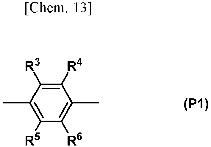
- In the formula, R3 and R6 are each independently a hydrogen atom, a halogen atom, a nitro group, a cyano group, or an alkyl group of 1 to 20 carbon atoms, alkenyl group of 2 to 20 carbon atoms, alkynyl group of 2 to 20 carbon atoms, aryl group of 6 to 20 carbon atoms or heteroaryl group of 2 to 20 carbon atoms which is optionally substituted with a halogen atom. Specific examples thereof include the same as those mentioned above for R1 and R2.
- In particular, R3 to R6 are preferably hydrogen atoms, fluorine atoms, cyano groups, alkyl groups of 1 to 20 carbon atoms which are optionally substituted with halogen atoms, aryl groups of 6 to 20 carbon atoms which are optionally substituted with halogen atoms, or heteroaryl groups of 2 to 20 carbon atoms which are optionally substituted with halogen atoms; more preferably hydrogen atoms, fluorine atoms, cyano groups, alkyl groups of 1 to 10 carbon atoms which are optionally substituted with halogen atoms, or phenyl groups which are optionally substituted with halogen atoms; even more preferably hydrogen atoms or fluorine atoms; and most preferably hydrogen atoms.
- Examples of suitable groups for Ph1 include, but are not limited to, a 1,4-phenylene group.
- Each Ar1 in formula (A1) is independently a group of any of formulas (B1) to (B 11), and more preferably a group of any of formulas (B1') to (B11').
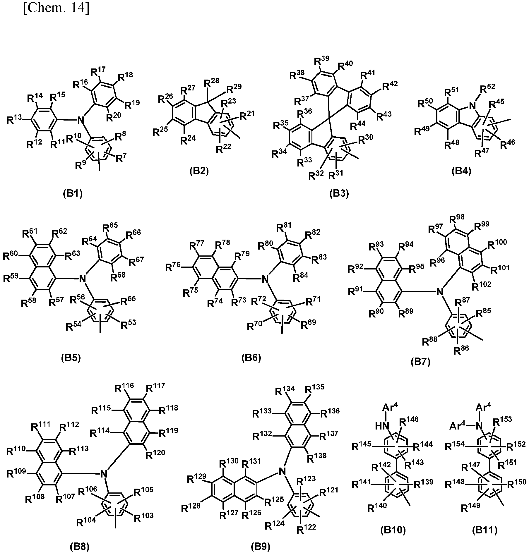

- In formulas (B1) to (B11) and (B1') to (B11'), R7 to R27, R30 to R51 and R53 to R154 are each independently a hydrogen atom, a halogen atom, a nitro group, a cyano group, or a diphenylamino group, an alkyl group of 1 to 20 carbon atoms, alkenyl group of 2 to 20 carbon atoms, alkynyl group of 2 to 20 carbon atoms, aryl group of 6 to 20 carbon atoms or heteroaryl group of 2 to 20 carbon atoms which is optionally substituted with a halogen atom. R28 and R29 are each independently an aryl group of 6 to 20 carbon atoms or a heteroaryl group of 2 to 20 carbon atoms which is optionally substituted with Z1. R52 is an aryl group of 6 to 20 carbon atoms or a heteroaryl group of 2 to 20 carbon atoms which is optionally substituted with Z1.
- Z1 is a halogen atom, a nitro group or a cyano group, or an alkyl group of 1 to 20 carbon atoms, an alkenyl group of 2 to 20 carbon atoms, or an alkynyl group of 2 to 20 carbon atoms which is optionally substituted with Z2. Z2 is a halogen atom, a nitro group or a cyano group, or an aryl group of 6 to 20 carbon atoms or a heteroaryl group of 2 to 20 carbon atoms which is substituted with Z3. Z3 is a halogen atom, a nitro group or a cyano group.
- In particular, R7 to R27, R30 to R51 and R53 to R154 are preferably hydrogen atoms, fluorine atoms, cyano groups, diphenylamino groups optionally substituted with halogen atoms, alkyl groups of 1 to 20 carbon atoms which are optionally substituted with halogen atoms, aryl groups of 6 to 20 carbon atoms which are optionally substituted with halogen atoms, or heteroaryl groups of 2 to 20 carbon atoms which are optionally substituted with halogen atoms; more preferably hydrogen atoms, fluorine atoms, cyano groups, alkyl groups of 1 to 10 carbon atoms which are optionally substituted with halogen atoms, or phenyl groups which are optionally substituted with halogen atoms; even more preferably hydrogen atoms or fluorine atoms; and most preferably hydrogen atoms.
- R28 and R29 are preferably aryl groups of 6 to 14 carbon atoms which are optionally substituted with halogen atoms or heteroaryl groups of 2 to 14 carbon atoms which are optionally substituted with halogen atoms; more preferably phenyl groups optionally substituted with halogen atoms or naphthyl groups optionally substituted with halogen atoms; even more preferably phenyl groups optionally substituted with halogen atoms; and still more preferably phenyl groups.
- R52 is preferably a hydrogen atom or an aryl group of 6 to 20 carbon atoms which is optionally substituted with Z1; more preferably a hydrogen atom, a phenyl group optionally substituted with Z1, or a naphthyl group optionally substituted with Z1; even more preferably a phenyl group optionally substituted with Z1; and still more preferably a phenyl group.
- Each Ar4 in formulae (B10), (B11), (B10') and (B11') is independently an aryl group of 6 to 20 carbon atoms, which is optionally substituted with a diarylamino group in which each aryl group is an aryl group of 6 to 20 carbon atoms. Specific examples of the aryl group of 6 to 20 carbon atoms include the same as those mentioned above for R1 and R2. Specific examples of the diarylamino group include diphenylamino, 1-naphthylphenylamino, di(1-naphthyl)amino, 1-naphthyl-2-naphthylamino and di(2-naphthyl)amino groups.
- Ar4 is preferably a phenyl, 1-naphthyl, 2-naphthyl, 1-anthryl, 2-anthryl, 9-anthryl, 1-phenanthryl, 2-phenanthryl, 3-phenanthryl, 4-phenanthryl, 9-phenanthryl, p-(diphenylamino)phenyl, p-(1-naphthylphenylamino)phenyl, p-(di(1-naphthyl)amino)phenyl, p-(1-naphthyl-2-naphthylamino)phenyl or p-(di(2-naphthyl)amino)phenyl group; and more preferably a p-(diphenylamino)phenyl group.
- Each Ar2 in formula (A1) is independently a group of any of formulas (C1) to (C18), and particularly preferably a group of any of formulas (C1'-1) to (C18'-2). In the following formula, Ar4 is the same as described above, and DPA is a diphenylamino group.


- In the formulae (C16), (C16'-1) and (C16'-2), R155 is a hydrogen atom, an aryl group of 6 to 14 carbon atoms which is optionally substituted with Z1, or a heteroaryl group of 2 to 14 carbon atoms which is optionally substituted with Z1. Examples of the aryl group and the heteroaryl group include the same as those mentioned above for R1 and R2. Of these, R155 is preferably a hydrogen atom, a phenyl group optionally substituted with Z1, a 1-naphthyl group optionally substituted with Z1, a 2-naphthyl group optionally substituted with Z1, a 2-pyridyl group optionally substituted with Z1, a 3-pyridyl group optionally substituted with a phenyl group optionally substituted with Z1, or a 4-pyridyl group optionally substituted with Z1; even more preferably a phenyl group optionally substituted with Z1; and even more preferably a phenyl group or a (2,3,5,6-tetrafluoro-4-(trifluoromethyl)phenyl) group.
- In formulae (C17), (C17'-1) and (C17'-2), R156 and R157 are aryl groups of 6 to 14 carbon atoms which are optionally substituted with phenyl groups optionally substituted with Z1, or heteroaryl groups of 2 to 14 carbon atoms which are optionally substituted with phenyl groups optionally substituted with Z1. Examples of the aryl group and the heteroaryl group include the same as those mentioned above for R1 and R2. Of these, R156 and R157 are preferably aryl groups of 6 to 14 carbon atoms which are optionally substituted with phenyl groups optionally substituted with Z1; and more preferably phenyl groups optionally substituted with phenyl groups optionally substituted with Z1, 1-naphthyl groups optionally substituted with phenyl groups optionally substituted with Z1, or 2-naphthyl groups optionally substituted with Z1.
- In the formula (A2), Ar3 is a group of any of formulae (D1) to (D8), and particularly preferably a group of any of (D1') to (D8').


- In formula (A1), the subscript is an integer from 1 to 10. From the standpoint of increasing the solubility of the compound in organic solvents, p is preferably from 1 to 5, more preferably from 1 to 3, even more preferably 1 or 2, and most preferably 1. In formula (A2), q is 1 or 2.
- The aniline derivative of formula (A1) and the aniline derivative of formula (A2) can be produced according to, for example, the method described in
WO 2015/050253 . - Other preferred examples of the tertiary aryl amine compound include compounds of the following formula (A3).

- In formula (A3), r is an integer of 2 to 4. Ar11 is an optionally substituted r-valent aromatic group of 6 to 20 carbon atoms. The aromatic group is a group obtained by removing r hydrogen atoms from an aromatic ring of an aromatic compound of 6 to 20 carbon atoms. The aromatic group is particularly preferably a group derived from a compound of any of the following formulae (A3-1) to (A3-8).

- In the formula, L1 to L3 are each independently a single bond, -(CR201R202)s-, -C(O)-, -O-, -S-, -S(O)-, -S(O2)- or -NR203-. s is an integer of 1 to 6. L4 to L13 are each independently a single bond, -CR201R202-, -C(O)-, -O-, -S-, -S(O)-, -S(O2)- or -NR203-. R201 and R202 are each independently a hydrogen atom or a monovalent hydrocarbon group of 1 to 20 carbon atoms. R201 and R202 may be bonded to each other to form a ring with carbon atoms to which these groups are bonded. In (CR201R202)s-, R201 and R202 may be identical to or different from each other when s is 2 or more. R203 is a hydrogen atom or a monovalent hydrocarbon group of 1 to 20 carbon atoms.
- The aromatic group is optionally substituted with substituents at some or all of hydrogen atoms thereof. Examples of the substituent include the same as those mentioned above for A1 in formula (1), and the substituent is preferably a halogen atom, a nitro group, a cyano group or a monovalent hydrocarbon group of 1 to 20 carbon atoms.
- Ar11 is preferably an optionally substituted 1,4-phenylene group, a fluorene-2,7-diyl group, a 9,9-dimethylfluorene-2,7-diyl group or the like, more preferably an optionally substituted 1,4-phenylene group or a biphenyl-4,4'-diyl group.
- In formula (A3), Ar12 and Ar13 are each independently a monovalent aromatic group of 6 to 20 carbon atoms which is optionally substituted with Z11. Ar12 and Ar13 may be bonded to each other to form a ring with nitrogen atoms to which these groups are bonded. Ar12 and Ar13 may be identical to or different from each other. Z11 is a halogen atom, a nitro group, a cyano group, or a monovalent aliphatic hydrocarbon group of 1 to 20 carbon atoms or a monovalent aromatic group which is optionally substituted with a halogen atom, or a polymerizable group.
- Examples of the monovalent aromatic group include aryl groups such as a phenyl group, a 1-naphthyl group, a 2-naphthyl group, a 1-anthryl group, a 2-anthryl group, a 9-anthryl group, a 1-phenanthryl group, a 2-phenanthryl group, a 3-phenanthryl group, a 4-phenanthryl group, a 9-phenanthryl group, a 2-biphenyl group, a 3-biphenyl group and a 4-biphenyl group.
- The monovalent aliphatic hydrocarbon may be linear, branched or cyclic, and specific examples thereof include alkyl groups of 1 to 20 carbon atoms such as a methyl group, an ethyl group, a n-propyl group, an isopropyl group, an n-butyl group, an isobutyl group, a sec-butyl group, a tert-butyl group, an n-pentyl group, a cyclohexyl group, an n-hexyl group, an n-cyclohexyl group, an n-heptyl group, an n-octyl group, an n-nonyl group, an n-decyl group, an n-undecyl group, and an n-dodecyl group; and alkenyl groups of 2 to 20 carbon atoms such as a vinyl group, a 1-propenyl group, a 2-propenyl group, an isopropenyl group, a 1-methyl-2-propenyl group, a 1-butenyl group, a 2-butenyl group, a 3-butenyl group and a hexenyl group.
- Examples of the polymerizable group include, but are not limited to, those of the following formula.

- In the formula, Ra is a hydrogen atom or a methyl group. Rb and Rd are each independently a hydrogen atom or an alkyl group of 1 to 6 carbon atoms, and preferably a methyl group or an ethyl group. Rc, Re and Rf are each independently a single bond or an alkylene group of 1 to 8 carbon atoms which optionally contains an oxygen atom, a sulfur atom or a nitrogen atom. Rg, Rh and Ri are each independently a hydrogen atom or an alkyl group of 1 to 10 carbon atoms such as a methyl group, an ethyl group or an n-propyl group.
- Ya and Yb are each independently a single bond or a divalent aromatic group of 6 to 20 carbon atoms. Examples of the divalent aromatic group include a 1,3-phenylene group, a 1,4-phenylene group, a 1,5-naphthylene group, a 1,6-naphthylene group, a 1,7-naphthylene group, a 2,6-naphthylene group and a 4,4'-biphenylylene group. Of these, a 1,3-phenylene group or a 1,4-phenylene group is preferred.
- Ara is a monovalent aromatic group of 6 to 20 carbon atoms which optionally has a substituent. Examples of the monovalent aromatic group include the same as those mentioned above.
- Z11 is preferably a methyl group, an ethyl group, or a polymerizable group of the following formula.

- Ar12 and Ar13 are each preferably a phenyl group, a 2-methylphenyl group, a 3-methylphenyl group, a 4-methylphenyl group, a 2-ethylphenyl group, a 3-ethylphenyl group, a 4-ethylphenyl group, a 2-vinylphenyl group, a 3-vinylphenyl group, a 4-vinylphenyl group, a 1-naphthyl group, a 2-naphthyl group or the like.
- The compound of formula (A3) can be synthesized by a known method, and a commercially available product can also be used.
- Other preferred examples of the tertiary aryl amine compound include those of the following formula (A4).

- In formula (A4), Ar21 to Ar23 are each independently a divalent aromatic group of 6 to 20 carbon atoms. The divalent aromatic group is furthermore preferably a divalent group derived from a compound of the above formula (A3-1), (A3-3) or (A3-4).
- Of these, Ar21 to Ar23 are each preferably a 1,4-phenylene group, a biphenyl-4,4'-diyl group, a terphenyl-4,4"-diyl group or the like, more preferably a 1,4-phenylene group or a biphenyl A -4,4'-diyl group.
- In formula (A4), Ar24 to Ar29 each independently represent a monovalent aromatic group of 6 to 20 carbon atoms which is substituted with Z21. Examples of the monovalent aromatic group include aryl groups such as a phenyl group, a 1-naphthyl group, a 2-naphthyl group, a 1-anthryl group, a 2-anthryl group, a 9-anthryl group, a 1-phenanthryl group, a 2-phenanthryl group, a 3-phenanthryl group, a 4-phenanthryl group, a 9-phenanthryl group, a 2-biphenyl group, a 3-biphenyl group and a 4-biphenyl group.
- Z21 is a halogen atom, a nitro group, a cyano group, a monovalent aliphatic hydrocarbon group of 1 to 20 carbon atoms which is optionally substituted with a halogen atom, a nitro group or a cyano group, -N(Ar30)(Ar31), or a polymerizable group. The monovalent aliphatic hydrocarbon group of 1 to 20 carbon atoms may be linear, branched or cyclic, and specific examples thereof include alkyl groups of 1 to 20 carbon atoms such as a methyl group, an ethyl group, an n-propyl group, an isopropyl group, an n-butyl group, an isobutyl group, a sec-butyl group, a tert-butyl group, an n-pentyl group, a cyclohexyl group, an n-hexyl group, an n-cyclohexyl group, an n-heptyl group, an n-octyl group, an n-nonyl group, an n-decyl group, an n-undecyl group, and an n-dodecyl group; and alkenyl groups of 2 to 20 carbon atoms such as a vinyl group, a 1-propenyl group, a 2-propenyl group, an isopropenyl group, a 1-methyl-2-propenyl group, a 1-butenyl group, a 2-butenyl group, a 3-butenyl group and a hexenyl group. Examples of the polymerizable group include the same as those mentioned above.
- Ar30 and Ar31 are each independently an aryl group of 6 to 20 carbon atoms which is optionally substituted with Z22. Ar30 and Ar31 may be bonded to each other to form a ring with nitrogen atoms to which these groups are bonded. Z22 is a halogen atom, a nitro group, a cyano group, or a monovalent aliphatic hydrocarbon group of 1 to 20 carbon atoms which is optionally substituted with a halogen atom, a nitro group or a cyano group.
- Examples of the aryl group of 6 to 20 carbon atoms and the monovalent aliphatic hydrocarbon group of 1 to 20 carbon atoms include the same as those mentioned above.
- Ar30 and Ar31 are each preferably a phenyl group, a 1-naphthyl group, a 2-naphthyl group, or a 1-biphenylyl group, more preferably a phenyl group, a 1-biphenylyl group or the like.
- In particular, -N(Ar30)(Ar31) is preferably a diphenylamino group, a phenyl(4-biphenylyl)amino group, a bis(4-biphenylyl)amino group, an N-carbazolyl group or the like.
- Z21 is preferably an alkyl group of 1 to 10 carbon atoms, -N(Ar30)(Ar31) or the like.
- Ar24 to Ar29 are each preferably a phenyl group, a 4-biphenylyl group, a 4-diphenylaminophenyl group, a 4-phenyl(4-biphenylyl)aminophenyl group, a bis(4-biphenylyl)aminophenyl group, a 4'-diphenylamino-4-biphenylyl group, a 4-phenyl(4-biphenylyl)amino-4-biphenylyl group, a 4'-bis(4-biphenylyl)amino-4-biphenylyl group, a N-carbazolylphenyl group, a 4'-N-carbazolyl- A 4-biphenylyl group or the like.
- The compound of formula (A4) can be synthesized by a known method, and a commercially available product can also be used.
- Other preferred examples of the tertiary aryl amine compound include polymers containing repeating units of the following formula (A5a) and repeating units of the following formula (A5b).

- In formula (A5a), Ar41 is a divalent aromatic group of 6 to 20 carbon atoms. Examples of the divalent aromatic group include the same as those mentioned above for Ar21 to Ar23 in formula (A4). Of these, a 1,4-phenylene group or a biphenyl-4,4'-diyl group is preferred.
- In formulae (A5a) and (A5b), R301 to R304 are each independently a monovalent hydrocarbon group of 1 to 20 carbon atoms, and are optionally substituted with -O-, -S-, -S(O)-, -S (O2)-, -NR'-, a carbonyl group, an ester bond or a sulfonic acid ester bond at a part of -CH2- which makes up the monovalent hydrocarbon group. R' is a hydrogen atom or a monovalent hydrocarbon group of 1 to 10 carbon atoms. The monovalent hydrocarbon group is preferably an alkyl group such as a methyl group, an ethyl group or an n-propyl group.
- In formula (A5b), R305 and R306 are each independently a hydrogen atom or a monovalent hydrocarbon group of 1 to 20 carbon atoms. Examples of the monovalent hydrocarbon group include the same as those mentioned above for X3 in formula (1). Of these, alkyl groups of 1 to 10 carbon atoms are preferred, and alkyl groups of 1 to 6 carbon atoms are more preferred.
- In formula (A5a), t is 0 or 1.
- m1 and m2 are each independently an integer of 0 to 4, and preferably 1 or 2, more preferably 1. m3 and m4 are each independently an integer of 0 to 3, and preferably 0 or 1, more preferably 0.
- The terminal of the polymer is optionally blocked with a polymerizable group. Examples of the polymerizable group include the same as those mentioned above.
- The lower limit of the weight average molecular weight (Mw) of the polymer is preferably 1,000, more preferably 5,000, even more preferably 10,000, still more preferably 15,000, most preferably 20,000. On the other hand, the upper limit of the weight average molecular weight (Mw) of the polymer is preferably 1,000,000, more preferably 500,000, still more preferably 200,000. In the invention, the weight average molecular weight (Mw) is a value measured by gel permeation chromatography (GPC) with tetrahydrofuran as a solvent, and calculated as polystyrene.
- The polymer can be synthesized by condensation polymerization of a triphenylamine compound which gives repeating units of formula (A5a) and a fluorene derivative which gives repeating units of formula (A5b), or a commercial products can also be used.
- Other preferred examples of the tertiary aryl amine compound include those of the following formula (A6).

- In the formula, Ar51 and Ar52 are each independently a phenyl group, a 1-naphthyl group or a 2-naphthyl group. R401 and R402 are each independently a hydrogen atom, a diarylaminophenyl group in which each aryl group is an aryl group of 6 to 20 carbon atoms, a chlorine atom, a bromine atom or an iodine atom. Examples of the aryl group include the same as those mentioned above for R1 and R2 in formula (A2). L21 is a divalent linking group containing a propane-2,2-diyl group or a 1,1,1,3,3,3-hexafluoropropane-2,2-diyl group. x is an integer of 1 or more.
- The compound of formula (A6) can be synthesized by a known method, and a commercially available product can also be used.
- Other preferred examples of the tertiary aryl amine compound include those of the following formula (A7).

- In formula (A7), Ar61 and Ar62 are each independently an optionally substituted monovalent aromatic group. Ar63 to Ar65 are each independently an optionally substituted divalent aromatic group. L31 is a linking group of any of the following formulae.

- In the formula, Ar66 to Ar71 and Ar74 to Ar78 are each independently an optionally substituted divalent aromatic group. Ar72 to Ar73 are each independently an optionally substituted monovalent aromatic group. R501 and R502 are each independently a hydrogen atom or any substituent. The substituent is not particularly limited, provided that the effects of the invention are not impaired, and examples thereof include the same as the substituents mentioned above for A1 in formula (1).
- The compound of formula (A7) can be synthesized by a known method, and a commercially available product can also be used.
- The tertiary aryl amine compound has at least one nitrogen atom is not limited to those described above, provided that all the nitrogen atoms form a tertiary aryl amine structure. Examples of other tertiary aryl amine compounds which can be used in the invention include arylamine compounds as described in
WO 2005/094133 , polymers as described inWO 2011/132702 , paragraph [0180], aromatic tertiary amine polymer compounds as described inWO 2014/073683 , fluorine atom-containing polymers as described inWO 2016/006674 , polymerizable compounds having a triarylamine partial structure and a polymerizable group as described inJP No. 5287455 JP No. 5381931 JP No. 5602191 JP No. 6177771 - Preferred examples of the tertiary aryl amine compounds include, but are not limited to, the following compounds.


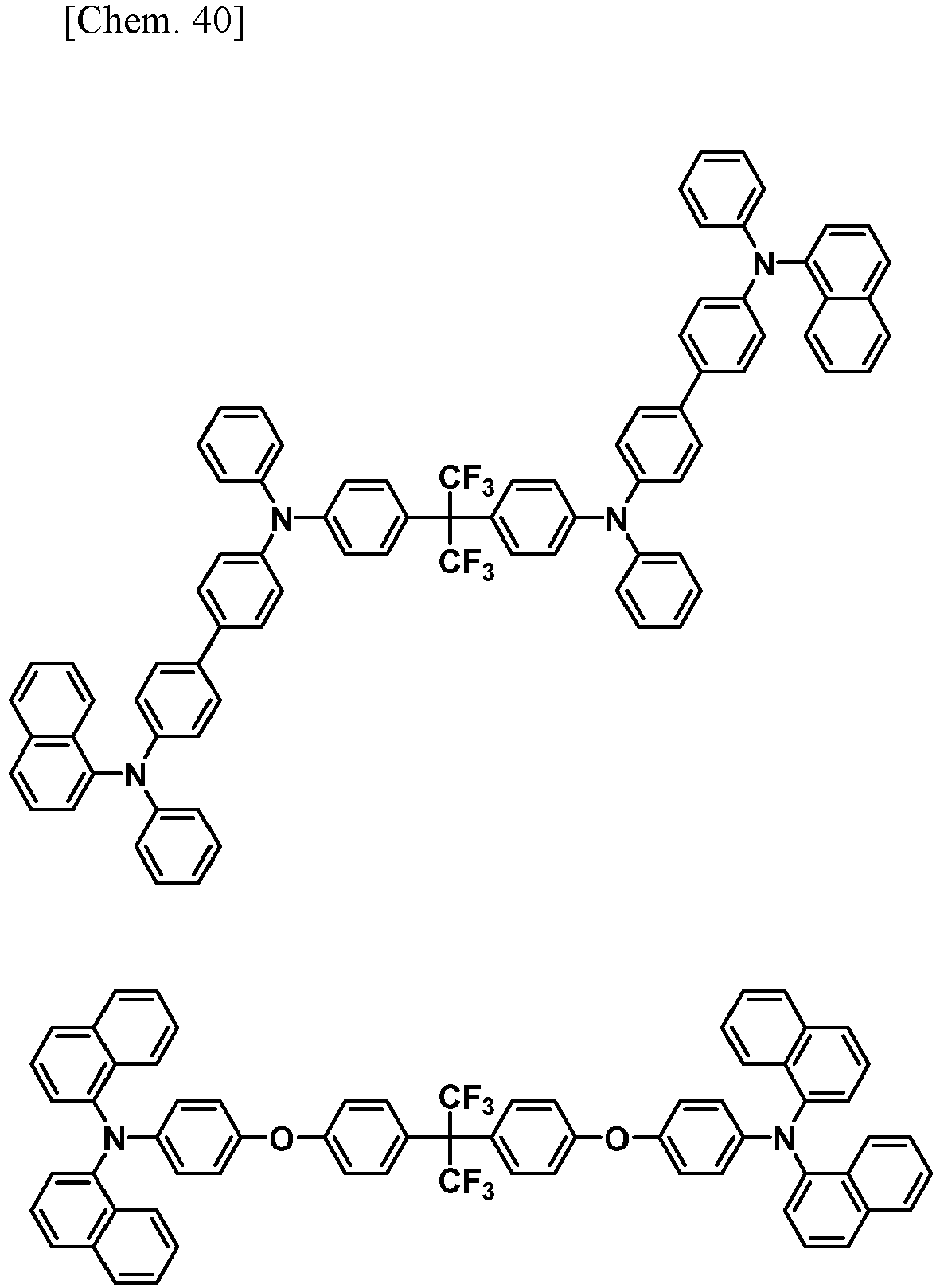
- A high-solvency solvent capable of dissolving well the above aryl sulfonate ester compounds and the tertiary aryl amine compounds may be used as the organic solvent employed when preparing the charge-transporting varnish of the invention. It is preferable to use a low-polarity solvent for dissolving the tertiary aryl amine compound and obtaining an amorphous coating film. To dissolve an unesterified sulfonic acid compound, it is necessary that at least one highly polar solvent be included. By contrast, it is possible to dissolve the above aryl sulfonate ester compounds in a solvent regardless of the polarity of the solvent. In the invention, a low-polarity solvent is defined as a solvent having a dielectric constant at a frequency of 100 kHz that is less than 7, and a high-polarity solvent is defined as a solvent having a dielectric constant at a frequency of 100 kHz that is 7 or more.
- Examples of low-polarity solvents include
chlorinated solvents such as chloroform and chlorobenzene;
aromatic hydrocarbon solvents such as toluene, xylene, tetralin, cyclohexylbenzene and decylbenzene;
aliphatic alcohol solvents such as 1-octanol, 1-nonanol and 1-decanol;
ether solvents such as tetrahydrofuran, dioxane, anisole, 4-methoxytoluene, 3-phenoxytoluene, dibenzyl ether, diethylene glycol dimethyl ether, diethylene glycol butyl methyl ether, triethylene glycol dimethyl ether and triethylene glycol butyl methyl ether; and
ester solvents such as methyl benzoate, ethyl benzoate, butyl benzoate, isoamyl benzoate, bis(2-ethylhexyl) phthalate, dibutyl maleate, dibutyl oxalate, hexyl acetate, diethylene glycol monoethyl ether acetate and diethylene glycol monobutyl ether acetate. - Examples of high-polarity solvents include
amide solvents such as N,N-dimethylformamide, N,N-dimethylacetamide, N,N-dimethylisobutyramide, N-methylpyrrolidone and 1,3-dimethyl-2-imidazolidinone;
ketone solvents such as ethyl methyl ketone, isophorone and cyclohexanone;
cyano solvents such as acetonitrile and 3-methoxypropionitrile;
polyhydric alcohol solvents such as ethylene glycol, diethylene glycol, triethylene glycol, dipropylene glycol, 1,3-butanediol and 2,3-butanediol;
monohydric alcohol solvents other than aliphatic alcohols, such as
diethylene glycol monomethyl ether, diethylene glycol monophenyl ether, triethylene glycol monomethyl ether, dipropylene glycol monomethyl ether, benzyl alcohol, 2-phenoxyethanol, 2-benzyloxyethanol, 3-phenoxybenzyl alcohol and tetrahydrofurfuryl alcohol; and
sulfoxide solvents such as dimethylsulfoxide. - Depending on the intended use, these solvents may be used singly, or in admixture of two or more thereof.
- It is preferable for all the charge-transporting substances to be in a completely dissolved or uniformly dispersed state in the above solvent, and more preferable for them to be completely dissolved.
- Examples of the method for preparing a charge-transporting varnish include, but are not limited to, a method in which component (A), component (B) and the like are added to a solvent in any order or at the same time. When there are a plurality of organic solvents, component (A), component (B) and the like may be dissolved in one solvent, followed by adding another solvent thereto, or component (A), component (B) and the like may be dissolved in a mixed solvent of a plurality of organic solvents in order or at the same time.
- From the standpoint of reproducibly obtaining thin films having a higher flatness, it is desirable for component (A), component (B) and the like to be obtained by dissolving the charge-transporting varnish in the organic solvent and subsequently filtering the solution using a submicron-order filter or the like.
- The solids concentration in the varnish of the invention, from the standpoint of ensuring a sufficient film thickness while minimizing deposition of the charge-transporting substance, is generally from about 0.1 to about 20% by weight, and preferably from 0.5 to 10% by weight. As used herein, the "solid" refers to the constituents which are contained in the varnish and which do not include solvents. The viscosity of the inventive varnish is generally from 1 to 50 mPa·s at 25°C.
- The content of the electron-accepting substance precursor within these solids, expressed as a molar ratio with respect to unity (1) for the charge-transporting substance, is preferably from about 0.01 to about 20, and more preferably from about 0.05 to about 15.
- The charge-transporting varnish of the present invention may further contain an organic silane compound. Examples of the organic silane compound include dialkoxysilane compounds, trialkoxysilane compounds and tetraalkoxysilane compounds. In particular, the organic silane compound is preferably a dialkoxysilane compound or a trialkoxysilane compound, and more preferably a trialkoxysilane compound. The organic silane compounds may be used singly, or in combination of two or more thereof.
- The content of the organic silane compound is typically from about 0.1 to 50% by weight based on the total mass of the charge-transporting substance and the dopant. Taking into account the suppression of deterioration of charge transportability of the resulting thin film and the enhancement of the hole-injecting ability into layers laminated so as to contact the hole-injecting layer on a side opposite to the anode, such as a hole-transporting layer and a light-emitting layer, the content of the organic silane compound is preferably from about 0.5 to 40% by weight, more preferably from about 0.8 to 30% by weight, still more preferably from about 1 to 20% by weight.
- A charge-transporting thin film can be formed on a substrate by applying the charge-transporting varnish of the invention onto the substrate and drying the applied varnish.
- Examples of methods for applying the varnish include, but are not limited to, dipping, spin coating, transfer printing, roll coating, brush coating, inkjet coating, spraying and slit coating. It is preferable for the viscosity and surface tension of the varnish to be adjusted according to the method of application.
- When using the varnish of the invention, the liquid film drying conditions are not particularly limited; one example is heating and firing on a hot plate. A dry film can be obtained by heating and firing in a temperature range of generally from about 100 to about 260°C for a period of from about 1 minute to about 1 hour. The firing atmosphere is not particularly limited.
- The thickness of the charge-transporting thin film is not particularly limited. However, when the thin film is to be used as a functional layer in an organic EL device, a film thickness of from 5 to 200 nm is preferred. Methods for changing the film thickness include, for example, changing the solids concentration in the varnish and changing the amount of solution on the substrate at the time of application.
- The organic EL device of the invention has a pair of electrodes and additionally has, between these electrodes, the above-described charge-transporting thin film of the invention.
- Typical organic EL device configurations include, but are not limited to, configurations (a) to (f) below. In these configurations, where necessary, an electron-blocking layer or the like may be provided between the light-emitting layer and the anode, and a hole-blocking layer or the like may be provided between the light-emitting layer and the cathode. Alternatively, the hole-injecting layer, hole-transporting layer or hole-injecting-and-transporting layer may also have the function of an electron-blocking layer or the like; and the electron-injecting layer, electron-transporting layer or electron-injecting-and-transporting layer may also have the function of a hole-blocking layer or the like.
- (a) anode/hole-injecting layer/hole-transporting layer/light-emitting layer/electron-transporting layer/electron-injecting layer/cathode
- (b) anode/hole-injecting layer/hole-transporting layer/light-emitting layer/electron-injecting-and-transporting layer/cathode
- (c) anode/hole-inj ecting-and-transporting layer/light-emitting layer/electron-transporting layer/electron-injecting layer/cathode
- (d) anode/hole-inj ecting-and-transporting layer/light-emitting layer/electron-inj ecting-and-transporting layer/cathode
- (e) anode/hole-injecting layer/hole-transporting layer/light-emitting layer/cathode
- (f) anode/hole-injecting-and-transporting layer/light-emitting layer/cathode
- As used herein, "hole-inj ecting layer," "hole-transporting layer" and "hole injecting-and-transporting layer" refer to layers which are formed between the light emitting layer and the anode and which have the function of transporting holes from the anode to the light-emitting layer. When only one layer of hole-transporting material is provided between the light-emitting layer and the anode, this is a "hole injecting and transporting layer"; when two or more layers of hole-transporting material are provided between the light-emitting layer and the anode, the layer that is closer to the anode is a "hole-injecting layer" and the other layer is a "hole-transporting layer." In particular, thin films having not only an excellent ability to accept holes from the anode but also an excellent ability to inject holes into, respectively, the hole-transporting layer and the light-emitting layer may be used as the hole-injecting layer and the hole injecting and-transporting layer.
- The "electron-injecting layer," "electron-transporting layer" and "electron injecting-and-transporting layer" refer to layers which are formed between the light-emitting layer and the cathode and which have the function of transporting electrons from the cathode to the light-emitting layer. When only one layer of electron-transporting material is provided between the light-emitting layer and the cathode, this is an "electron injecting-and-transporting layer"; when two or more layers of electron transporting material are provided between the light-emitting layer and the cathode, the layer that is closer to the cathode is an "electron-injecting layer" and the other layer is an "electron-transporting layer."
- The "light-emitting layer" is an organic layer having a light-emitting function. When a doping system is used, this layer includes a host material and a dopant material. The function of the host material is primarily to promote the recombination of electrons and holes and to confine the resulting excitons within the light-emitting layer. The function of the dopant material is to cause the excitons obtained by recombination to efficiently luminesce. In the case of phosphorescent devices, the host material functions primarily to confine within the light-emitting layer the excitons generated by the dopant.
- The materials and method employed to produce an organic EL device using the charge-transporting varnish of the invention are exemplified by, but not limited to, those described below.
- The electrode substrate to be used is preferably cleaned beforehand by liquid washing with, for example, a cleaning agent, alcohol or pure water. For example, when the electrode substrate is an anode substrate, it is preferably subjected to surface treatment such as UV/ozone treatment or oxygen-plasma treatment just prior to use. However, surface treatment need not be carried out in cases where the anode material contains an organic substance as a principal component.
- An example is described below of a method for producing the organic EL device of the invention in which a thin-film obtained from the charge-transporting varnish of the invention serves as the hole-injecting layer.
- Using the above-described method, a hole-injecting layer is formed on an electrode by applying the charge-transporting varnish of the invention onto an anode substrate and then firing the applied varnish. A hole-transporting layer, a light-emitting layer, an electron-transporting layer, an electron-injecting layer and a cathode are provided in this order on the hole-injecting layer. The hole-transporting layer, light-emitting layer, electron-transporting layer and electron-injecting layer may be formed by either a vapor deposition process or a coating process (wet process), depending on the properties of the material used.
- Illustrative examples of anode materials include transparent electrodes such as indium-tin oxide (ITO) and indium-zinc oxide (IZO), and metal anodes made of a metal such as aluminum or an alloy of such a metal. An anode material on which planarizing treatment has been carried out is preferred. Use can also be made of polythiophene derivatives and polyaniline derivatives having a high charge transportability.
- Examples of other metals that may make up the metal anode include, but are not limited to, scandium, titanium, vanadium, chromium, manganese, iron, cobalt, nickel, copper, zinc, gallium, yttrium, zirconium, niobium, molybdenum, ruthenium, rhodium, palladium, cadmium, indium, scandium, lanthanum, cerium, praseodymium, neodymium, promethium, samarium, europium, gadolinium, terbium, dysprosium, holmium, erbium, thulium, ytterbium, hafnium, thallium, tungsten, rhenium, osmium, iridium, platinum, gold, titanium, lead, bismuth, and alloys thereof.
- Specific examples of hole-transporting layer-forming materials include the following hole-transporting low-molecular-weight materials: triarylamines such as (triphenylamine) dimer derivatives, [(triphenylamine) dimer] spirodimer, N,N'-bis(naphthalen-1-yl)-N,N'-bis(phenyl)benzidine (α-NPD), N,N'-bis(naphthalen-2-yl)-N,N'-bis(phenyl)benzidine, N,N'-bis(3-methylphenyl)-N,N'-bis(phenyl)benzidine, N,N'-bis(3-methylphenyl)-N,N'-bis(phenyl)-9,9-spirobifluorene, N,N'-bis(naphthalen-1-yl)-N,N'-bis(phenyl)-9,9-spirobifluorene, N,N'-bis(3-methylphenyl)-N,N'-bis(phenyl)-9,9-dimethylfluorene, N,N'-bis(naphthalen-1-yl)-N,N'-bis(phenyl)-9,9-dimethylfluorene, N,N'-bis(3-methylphenyl)-N,N'-bis(phenyl)-9,9-diphenylfluorene, N,N'-bis(naphthalen-1-yl)-N,N'-bis(phenyl)-9,9-diphenylfluorene, N,N'-bis(naphthalen-1-yl)-N,N'-bis(phenyl)-2,2'-dimethylbenzidine, 2,2',7,7'-tetrakis(N,N-diphenylamino)-9,9-spirobifluorene, 9,9-bis[4-(N,N-bis-biphenyl-4-ylamino)phenyl]-9H-fluorene, 9,9-bis[4-(N,N-bisnaphthalen-2-ylamino)phenyl]-9H-fluorene, 9,9-bis[4-(N-naphthalen-1-yl-N-phenylamino)phenyl]-9H-fluorene, 2,2',7,7'-tetrakis[N-naphthalenyl(phenyl)amino]-9,9-spirobifluorene, N,N'-bis(phenanthren-9-yl)-N,N'-bis(phenyl)benzidine, 2,2'-bis[N,N-bis(biphenyl-4-yl)amino]-9,9-spirobifluorene, 2,2'-bis(N,N-diphenylamino)-9,9-spirobifluorene, di[4-(N,N-di(p-tolyl)amino)phenyl]cyclohexane, 2,2',7,7' -tetra(N,N-di(p-tolyl))amino-9,9-spirobifluorene, N,N,N',N'-tetra-naphthalen-2-yl-benzidine, N,N,N',N'-tetra(3-methylphenyl)-3,3'-dimethylbenzidine, N,N'-di(naphthalenyl)-N,N'-di(naphthalen-2-yl)benzidine, N,N,N',N'-tetra(naphthalenyl)benzidine, N,N'-di(naphthalen-2-yl)-N,N'-diphenylbenzidine-1-4-diamine, N1,N4-diphenyl-N1,N4-di(m-tolyl)benzene-1,4-diamine, N2,N2,N6,N6-tetraphenylnaphthalene-2,6-diamine, tris(4-(quinolin-8-yl)phenyl)amine, 2,2'-bis(3-(N,N-di(p-tolyl)amino)phenyl)biphenyl, 4,4',4"-tris[3-methylphenyl(phenyl)amino]triphenylamine (m-MTDATA) and 4,4',4"-tris[1-naphthyl(phenyl)amino]triphenylamine (1-TNATA); and oligothiophenes such as 5,5"-bis-{4-[bis(4-methylphenyl)amino]phenyl}-2,2':5',2"-terthiophene (BMA-3T).
- Specific examples of light-emitting layer-forming materials include tris(8-quinolinolate) aluminum(III) (Alq3), bis(8-quinolinolate) zinc(II) (Znq2), bis(2-methyl-8-quinolinolate)-4-(p-phenylphenolate) aluminum(III) (BAlq), 4,4'-bis(2,2-diphenylvinyl)biphenyl, 9,10-di(naphthalen-2-yl)anthracene, 2-tert-butyl-9,10-di(naphthalen-2-yl)anthracene, 2,7-bis[9,9-di(4-methylphenyl)-fluoren-2-yl]-9,9-di(4-methylphenyl)fluorene, 2-methyl-9,10-bis(naphthalen-2-yl)anthracene, 2-(9,9-spirobifluoren-2-yl)-9,9-spirobifluorene, 2,7-bis(9,9-spirobifluoren-2-yl)-9,9-spirobifluorene, 2-[9,9-di(4-methylphenyl)-fluoren-2-yl]-9,9-di(4-methylphenyl)fluorene, 2,2'-dipyrenyl-9,9-spirobifluorene, 1,3,5-tris(pyren-1-yl)benzene, 9,9-bis[4-(pyrenyl)phenyl]-9H-fluorene, 2,2'-bi(9,10-diphenylanthracene), 2,7-dipyrenyl-9,9-spirobifluorene, 1,4-di(pyren-1-yl)benzene, 1,3-di(pyren-1-yl)benzene, 6,13-di(biphenyl-4-yl)pentacene, 3,9-di(naphthalen-2-yl)perylene, 3,10-di(naphthalen-2-yl)perylene, tris[4-(pyrenyl)-phenyl]amine, 10,10' -di(biphenyl-4-yl)-9,9' -bianthracene, N,N'-di(naphthalen-1-yl)-N,N'-diphenyl-[1,1':4',1":4",1'"-quaterphenyl]-4,4"'-diamine, 4,4'-di[10-(naphthalen-1-yl)anthracen-9-yl]biphenyl, dibenzo{[f,f']-4,4',7,7'-tetraphenyl}diindeno[1,2,3-cd:1',2',3'-lm]perylene, 1-(7-(9,9'-bianthracen-10-yl)-9,9-dimethyl-9H-fluoren-2-yl)pyrene, 1-(7-(9,9'-bianthracen-10-yl)-9,9-dihexyl-9H-fluoren-2-yl)pyrene, 1,3-bis(carbazol-9-yl)benzene, 1,3,5-tris(carbazol-9-yl)benzene, 4,4',4"-tris(carbazol-9-yl)triphenylamine, 4,4'-bis(carbazol-9-yl)biphenyl (CBP), 4,4'-bis(carbazol-9-yl)-2,2'-dimethylbiphenyl, 2,7-bis(carbazol-9-yl)-9,9-dimethylfluorene, 2,2',7,7'-tetrakis(carbazol-9-yl)-9,9-spirobifluorene, 2,7-bis(carbazol-9-yl)-9,9-di(p-tolyl)fluorene, 9,9-bis[4-(carbazol-9-yl)-phenyl]fluorene, 2,7-bis(carbazol-9-yl)-9,9-spirobifluorene, 1,4-bis(triphenylsilyl)benzene, 1,3-bis(triphenylsilyl)benzene, bis(4-N,N-diethylamino-2-methylphenyl)-4-methylphenylmethane, 2,7-bis(carbazol-9-yl)-9,9-dioctylfluorene, 4,4"-di(triphenylsilyl)-p-terphenyl, 4,4'-di(triphenylsilyl)biphenyl, 9-(4-tert-butylphenyl)-3,6-bis(triphenylsilyl)-9H-carbazole, 9-(4-tert-butylphenyl)-3,6-ditrityl-9H-carbazole, 9-(4-tert-butylphenyl)-3,6-bis(9-(4-methoxyphenyl)-9H-fluoren-9-yl)-9H-carbazole, 2,6-bis(3-(9H-carbazol-9-yl)phenyl)pyridine, triphenyl(4-(9-phenyl-9H-fluoren-9-yl)phenyl)silane, 9,9-dimethyl-N,N-diphenyl-7-(4-(1-phenyl-1H-benzo[d]imidazol-2-yl)phenyl-9H-fluoren-2-amine, 3,5-bis(3-(9H-carbazol-9-yl)phenyl)pyridine, 9,9-spirobifluoren-2-yl-diphenyl-phosphine oxide, 9,9'-(5-triphenylsilyl)-1,3-phenylene)bis(9H-carbazole), 3-(2,7-bis(diphenylphosphoryl)-9-phenyl-9H-fluoren-9-yl)-9-phenyl-9H-carbazole, 4,4,8,8,12,12-hexa(p-tolyl)-4H-8H-12H-12C-azadibenzo[cd,mn]pyrene, 4,7-di(9H-carbazol-9-yl)-1,10-phenanthroline, 2,2'-bis(4-(carbazol-9-yl)phenyl)biphenyl, 2,8-bis(diphenylphosphoryl)dibenzo[b,d]thiophene, bis(2-methylphenyl)diphenylsilane, bis[3,5-di(9H-carbazol-9-yl)phenyl]diphenylsilane, 3,6-bis(carbazol-9-yl)-9-(2-ethylhexyl)-9H-carbazole, 3-(diphenylphosphoryl)-9-(4-(diphenylphosphoryl)phenyl)-9H-carbazole and 3,6-bis[(3,5-diphenyl)phenyl]-9-phenylcarbazole. The light-emitting layer may be formed by the co-vapor deposition of these materials with a light-emitting dopant.
- Specific examples of light-emitting dopants include 3-(2-benzothiazolyl)-7-(diethylamino)coumarin, 2,3,6,7-tetrahydro-1,1,7,7-tetramethyl-1H,5H,11H-10-(2-benzothiazolyl)quinolidino-[9,9a,1gh]coumarin, quinacridone, N,N'-dimethylquinacridone, tris(2-phenylpyridine)iridium(III) (Ir(ppy)3), bis(2-phenylpyridine)(acetylacetonate) iridium(III) (Ir(ppy)2(acac)), tris[2-(p-tolyl)pyridine]iridium(III) (Ir(mppy)3), 9,10-bis[N,N-di(p-tolyl)amino]anthracene, 9,10-bis[phenyl(m-tolyl)amino]anthracene, bis[2-(2-hydroxyphenyl)benzothiazolate] zinc(II), N10,N10,N10,N10-tetra(p-tolyl)-9,9'-bianthracene-10,10'-diamine, N10,N10,N10,N10-tetraphenyl-9,9'-bianthracene-10,10'-diamine, N10,N10-diphenyl-N10,N10-dinaphthalenyl-9,9'-bianthracene-10,10'-diamine, 4,4'-bis(9-ethyl-3-carbazovinylene)-1,1'-biphenyl, perylene, 2,5,8,11-tetra-tert-butylperylene, 1,4-bis[2-(3-N-ethylcarbazolyl)vinyl]benzene, 4,4'-bis[4-(di-p-tolylamino)styryl]biphenyl, 4-(di-p-tolylamino)-4'-[(di-p-tolylamino)styryl]stilbene, bis[3,5-difluoro-2-(2-pyridyl)phenyl-(2-carboxypyridyl)] iridium(III), 4,4'-bis[4-(diphenylamino)styryl]biphenyl, bis(2,4-difluorophenylpyridinato)tetrakis(1-pyrazolyl)borate iridium(III), N,N'-bis(naphthalen-2-yl)-N,N'-bis(phenyl)-tris(9,9-dimethylfluorenylene), 2,7-bis{2-[phenyl(m-tolyl)amino]-9,9-dimethylfluoren-7-yl}-9,9-dimethylfluorene, N-(4-((E)-2-(6((E)-4-(diphenylamino)styryl)naphthalen-2-yl)vinyl)phenyl)-N-phenylbenzenamine, fac-iridium(III) tris(1-phenyl-3-methylbenzimidazolin-2-ylidene-C,C2), mer-iridium(III) tris(1-phenyl-3-methylbenzimidazolin-2-ylidene-C,C2), 2,7-bis[4-(diphenylamino)styryl]-9,9-spirobifluorene, 6-methyl-2-(4-(9-(4-(6-methylbenzo[d]thiazol-2-yl)phenyl)anthracen-10-yl)phenyl)benzo-[d]thiazole, 1,4-di[4-(N,N-diphenyl)amino]styrylbenzene, 1,4-bis(4-(9H-carbazol-9-yl)styryl)benzene, (E)-6-(4-(diphenylamino)styryl)-N,N-diphenylnaphthalen-2-amine, bis(2,4-difluorophenylpyridinato)(5-(pyridin-2-yl)-1H-tetrazolate) iridium(III), bis(3-trifluoromethyl-5-(2-pyridyl)pyrazole)((2,4-difluorobenzyl)diphenylphosphinate) iridium(III), bis(3-trifluoromethyl-5-(2-pyridyl)pyrazolate)(benzyldiphenylphosphinate) iridium(III), bis(1-(2,4-difluorobenzyl)-3-methylbenzimidazolium)(3-(trifluoromethyl)-5-(2-pyridyl)-1,2,4-triazolate) iridium(III), bis(3-trifluoromethyl-5-(2-pyridyl)pyrazolate)(4',6'-difluorophenylpyridinate) iridium(III), bis(4',6'-difluorophenylpyridinato)(3,5-bis(trifluoromethyl)-2-(2'-pyridyl)pyrrolate) iridium(III), bis(4',6'-difluorophenylpyridinato)(3-(trifluoromethyl)-5-(2-pyridyl)-1,2,4-triazolate) iridium (III), (Z)-6-mesityl-N-(6-mesitylquinolin-2(1H)-ylidene)quinoline-2-amine-BF2, (E)-2-(2-(4-(dimethylamino)styryl)-6-methyl-4H-pyran-4-ylidene)malononitrile, 4-(dicyanomethylene)-2-methyl-6-julolidyl-9-enyl-4H-pyran, 4-(dicyanomethylene)-2-methyl-6-(1,1,7,7-tetramethyljulolidyl-9-enyl)-4H-pyran, 4-(dicyanomethylene)-2-tert-butyl-6-(1,1,7,7-tetramethyljulolidin-4-ylvinyl)-4H-pyran, tris(dibenzoylmethane)phenanthroline europium(III), 5,6,11,12-tetraphenylnaphthacene, bis(2-benzo[b]thiophen-2-yl-pyridine)(acetylacetonate) iridium(III), tris(1-phenylisoquinoline) iridium(III), bis(1-phenylisoquinoline)(acetylacetonate) iridium(III), bis[1-(9,9-dimethyl-9H-fluoren-2-yl)isoquinoline](acetylacetonate) iridium(III), bis[2-(9,9-dimethyl-9H-fluoren-2-yl)quinoline](acetylacetonate) iridium(III), tris[4,4'-di-tert-butyl-(2,2')-bipyridine]ruthenium(III)·bis(hexafluorophosphate), tris(2-phenylquinoline) iridium(III), bis(2-phenylquinoline)(acetylacetonate) iridium(III), 2,8-di-tert-butyl-5,11-bis(4-tert-butylphenyl)-6,12-diphenyltetracene, bis(2-phenylbenzothiazolate)(acetylacetonate) iridium(III), platinum 5,10,15,20-tetraphenyltetrabenzoporphyrin, osmium(II) bis(3-trifluoromethyl-5-(2-pyridine)pyrazolate)dimethylphenylphosphine, osmium(II) bis(3-trifluoromethyl)-5-(4-tert-butylpyridyl)-1,2,4-triazolate)diphenylmethylphosphine, osmium(II) bis(3-(trifluoromethyl)-5-(2-pyridyl)-1,2,4-triazole)dimethylphenylphosphine, osmium(II) bis(3-(trifluoromethyl)-5-(4-tert-butylpyridyl)-1,2,4-triazolate)dimethylphenylphosphine, bis[2-(4-n-hexylphenyl)quinoline](acetylacetonate) iridium(III), tris[2-(4-n-hexylphenyl)quinoline]iridium(III), tris[2-phenyl-4-methylquinoline] iridium(III), bis(2-phenylquinoline)(2-(3-methylphenyl)pyridinate) iridium(III), bis(2-(9,9-diethylfluoren-2-yl)-1-phenyl-1H-benzo[d]imidazolato)(acetylacetonate) iridium(III), bis(2-phenylpyridine)(3-(pyridin-2-yl)-2H-chromen-2-onate) iridium(III), bis(2-phenylquinoline)(2,2,6,6-tetramethylheptane-3,5-dionate) iridium(III), bis(phenylisoquinoline)(2,2,6,6-tetramethylheptane-3,5-dionate) iridium(III), iridium(III) bis(4-phenylthieno[3,2-c]pyridinato-N,C2)acetylacetonate, (E)-2-(2-tert-butyl-6-(2-(2,6,6-trimethyl-2,4,5,6-tetrahydro-1H-pyrrolo[3,2,1-ij]quinolin-8-yl)vinyl)-4H-pyran-4-ylidene)malononitrile, bis(3-trifluoromethyl-5-(1-isoquinolyl)pyrazolate)(methyldiphenylphosphine) ruthenium, bis[(4-n-hexylphenyl)isoquinoline](acetylacetonate) iridium(III), platinum(II) octaethylporphin, bis(2-methyldibenzo[f,h]quinoxaline)(acetylacetonate) iridium(III) and tris[(4-n-hexylphenyl)isoquinoline] iridium(III).
- Specific examples of electron-transporting layer-forming materials include lithium 8-hydroxyquinolinate, 2,2',2"-(1,3,5-benzinetriyl)-tris(1-phenyl-1-H-benzimidazole), 2-(4-biphenyl)-5-(4-tert-butylphenyl)-1,3,4-oxadiazole, 2,9-dimethyl-4,7-diphenyl-1,10-phenanthroline, 4,7-diphenyl-1,10-phenanthroline, bis(2-methyl-8-quinolinolate)-4-(phenylphenolato)aluminum, 1,3-bis[2-(2,2'-bipyridin-6-yl)-1,3,4-oxadiazo-5-yl]benzene, 6,6'-bis[5-(biphenyl-4-yl)-1,3,4-oxadiazo-2-yl]-2,2'-bipyridine, 3-(4-biphenyl)-4-phenyl-5-tert-butylphenyl-1,2,4-triazole, 4-(naphthalen-1-yl)-3,5-diphenyl-4H-1,2,4-triazole, 2,9-bis(naphthalen-2-yl)-4,7-diphenyl-1,10-phenanthroline, 2,7-bis[2-(2,2'-bipyridin-6-yl)-1,3,4-oxadiazo-5-yl]-9,9-dimethylfluorene, 1,3-bis[2-(4-tert-butylphenyl)-1,3,4-oxadiazo-5-yl]benzene, tris(2,4,6-trimethyl-3-(pyridin-3-yl)phenyl)borane, 1-methyl-2-(4-(naphthalen-2-yl)phenyl)-1H-imidazo[4,5f][1,10]phenanthroline, 2-(naphthalen-2-yl)-4,7-diphenyl-1,10-phenanthroline, phenyldipyrenylphosphine oxide, 3,3',5,5'-tetra[(m-pyridyl)-phen-3-yl]biphenyl, 1,3,5-tris[(3-pyridyl)-phen-3-yl]benzene, 4,4'-bis(4,6-diphenyl-1,3,5-triazin-2-yl)biphenyl, 1,3-bis[3,5-di(pyridin-3-yl)phenyl]benzene, bis(10-hydroxybenzo[h]quinolinato)beryllium, diphenylbis(4-(pyridin-3-yl)phenyl)silane and 3,5-di(pyren-1-yl)pyridine.
- Examples of electron-injecting layer-forming materials include lithium oxide (Li2O), magnesium oxide (MgO), alumina (Al2O3), lithium fluoride (LiF), sodium fluoride (NaF), magnesium fluoride (MgF2), cesium fluoride (CsF), strontium fluoride (SrF2), molybdenum trioxide (MoO3), aluminum, lithium acetylacetonate (Li(acac)), lithium acetate and lithium benzoate.
- Examples of cathode materials include aluminum, magnesium-silver alloys, aluminum-lithium alloys, lithium, sodium, potassium and cesium.
- Another example is described below of a method for producing the organic EL device of the invention in which a thin-film obtained from the charge-transporting varnish of the invention serves as the hole-injecting layer.
- An organic EL device having a charge-transporting thin film formed with the charge-transporting varnish of the invention can be produced by, in the organic EL device production method described above, successively forming a hole-transporting layer and a light-emitting layer instead of carrying out vacuum evaporation operations for a hole transporting layer, a light-emitting layer, an electron-transporting layer and an electron-injecting layer. Specifically, the charge-transporting varnish of the invention is applied onto an anode substrate, and a hole-injecting layer is formed by the above described method. A hole-transporting layer and a light-emitting layer are then successively formed thereon, following which a cathode material is vapor-deposited on top, thereby giving an organic EL device.
- The cathode and anode materials used here may be similar to those described above, and similar cleaning treatment and surface treatment may be carried out.
- The method of forming the hole-transporting layer and the light-emitting layer is exemplified by a film-forming method that involves adding a solvent to a hole-transporting polymer material or a light-emitting polymer material, or to the material obtained by adding a dopant to either of these, thereby dissolving or uniformly dispersing the material, and then applying the solution or dispersion onto the hole-injecting layer or the hole-transporting layer and subsequently firing.
- Examples of hole-transporting polymer materials include poly[(9,9-dihexylfluorenyl-2,7-diyl)-co-(N,N'-bis{p-butylphenyl}-1,4-diaminophenylene)], poly[(9,9-dioctylfluorenyl-2,7-diyl)-co-(N,N'-bis{p-butylphenyl}-1,1'-biphenylene-4,4-diamine)], poly[(9,9-bis{1'-penten-5'-yl}fluorenyl-2,7-diyl)-co-(N,N'-bis{p-butylphenyl}-1,4-diaminophenylene)], poly[N,N'-bis(4-butylphenyl)-N,N'-bis(phenyl)-benzidine] end-capped with polysilsesquioxane and poly[(9,9-dioctylfluorenyl-2,7-diyl)-co-(4,4'-(N-(p-butylphenyl))diphenylamine)] (TFB).
- Examples of light-emitting polymer materials include polyfluorene derivatives such as poly(9,9-dialkylfluorene) (PDAF), poly(phenylene vinylene) derivatives such as poly(2-methoxy-5-(2'-ethylhexoxy)-1,4-phenylene vinylene) (MEH-PPV), polythiophene derivatives such as poly(3-alkylthiophene) (PAT), and polyvinylcarbazole (PVCz).
- Examples of solvents include toluene, xylene and chloroform. Examples of the method of dissolution or uniform dispersion include stirring, stirring under applied heat, and ultrasonic dispersion.
- Examples of the method of application include, but are not particularly limited to, inkjet coating, spraying, dipping, spin coating, transfer printing, roll coating and brush coating. Application is preferably carried out in an inert gas atmosphere such as nitrogen or argon.
- Examples of the firing method include methods that involve heating in an oven or on a hot plate, either within an inert gas atmosphere or in a vacuum.
- An example is described below of a method for producing the organic EL device of the invention in cases where a thin film obtained from the charge-transporting varnish of the invention serves as a hole-injecting-and-transporting layer.
- A hole-injecting-and-transporting layer is formed on an anode substrate. A light emitting layer, an electron-transporting layer, an electron-injecting layer and a cathode are provided in this order on the hole-injecting-and-transporting layer. Methods of forming the light-emitting layer, electron-transporting layer and electron-injecting layer, and specific examples thereof, include the same as those mentioned above.
- The anode material, the light-emitting layer, the light-emitting dopant, the materials which form the electron-transporting layer and the electron-blocking layer, and the cathode material are exemplified in the same way as mentioned above.
- A hole-blocking layer, an electron-blocking layer or the like may be optionally provided between the electrodes and any of the above layers. By way of illustration, an example of a material that forms an electron-blocking layer is tris(phenylpyrazole)iridium.
- The materials which make up the anode, the cathode and the layers formed therebetween differ according to whether a device provided with a bottom emission structure or a top emission structure is to be fabricated, and so are suitably selected while taking this into account.
- Typically, in a device having a bottom emission structure, a transparent anode is used on the substrate side and light is extracted from the substrate side, whereas in a device having a top emission structure, a reflective anode made of metal is used and light is extracted from the transparent electrode (cathode) side in the opposite direction from the substrate. Hence, for example, with regard to the anode material, when fabricating a device having a bottom emission structure, a transparent anode of ITO or the like is used, and when fabricating a device having a top emission structure, a reflective anode of Al/Nd or the like is used.
- To prevent deterioration of the device characteristics, the organic EL device of the invention may be sealed in the usual manner with, if necessary, a desiccant or the like.
- Examples and Comparative Examples are given below to more concretely illustrate the invention, although the invention is not limited by these Examples. In the Examples, the following equipment was used for sample preparation and for analyzing physical properties.
(1) 1H-NMR, 19F-NMR: Nuclear magnetic resonance apparatus AL-300, from JEOL Ltd. (2) LC/MS: ZQ 2000, from Waters Corporation (3) Substrate Cleaning: Substrate cleaning machine (reduced-pressure plasma system), from Choshu Industry Co., Ltd. (4) Varnish Coating: MS-A100 Spin Coater, from Mikasa Co., Ltd. (5) Film Thickness Measurement: Surfcorder ET-4000 microfigure measuring instrument, from Kosaka Laboratory, Ltd. (6) EL Device Fabrication: C-E2L1G1-N Multifunction Vapor Deposition System, from Choshu Industry Co., Ltd. (7) Measurement of luminance of ELelement, etc.: Multi-channel IVL measurement apparatus, from EHC Co., Ltd. - The aryl sulfonate ester compound NSO-2-PGEE was synthesized in accordance with the following scheme.

- Under a nitrogen atmosphere, 4.8 g (14.36 mol) of perfluorobiphenyl, 4.2 g (30.15 mol) of potassium carbonate and 100 mL of N,N-dimethylformamide were successively added to 11 g (31.59 mmol) of sodium 1-naphthol-3,6-disulfonate, and the reaction system was flushed with nitrogen and subsequently stirred for 6 hours at an internal temperature of 100°C. The system was allowed to cool to room temperature, following which the potassium carbonate residue was removed by filtration and vacuum concentration was carried out. To remove the remaining impurities, 100 mL of methanol was added to the residue and stirring was carried out for 30 minutes at room temperature. The suspension was then filtered, giving 11.8 g (yield: 83%) of NSO-2-Na.
- Thionyl chloride (8 mL) and N,N-dimethylformamide (DMF) (0.1 mL) as a catalyst were added to 2 g (2 mmol) of NSO-2-Na, and the system was refluxed under heating for 1 hour, following which the thionyl chloride was driven off, giving a solid containing NSO-2-Cl. This compound was used in the next step without further purification.
- Chloroform (12 mL) and pyridine (8 mL) were added to the solid, and 2.50 g (24 mmol) of propylene glycol monoethyl ether (Junsei Chemical Co., Ltd.) was added at 0°C. The temperature was raised to room temperature and 3 hours of stirring was carried out thereafter. The solvent was driven off, following which water was added, extraction was carried out with ethyl acetate, and the organic layer was dried over sodium sulfate. After filtration and concentration, the resulting crude product was purified by silica gel column chromatography (hexane/ethyl acetate), giving 1.09 g of the aryl sulfonate ester compound NSO-2-PGEE (hereinafter, referred to as NSO-2-PGEE-1) as a white solid (yield: 44% (2-step yield from NSO-2-Na)). The results of 1H-NMR and LC/MS measurement are shown below.
1H-NMR (500 MHz, CDCl3): - δ 0.92-0.97 (m, 12H), 1.34 and 1.40 (a pair of d, J = 6.5 Hz, 12H), 3.32-3.52 (m, 16H), 4.80-4.87 (m, 4H), 7.37 (s, 2H), 8.22 (d, J = 8.5 Hz, 2H), 8.45 (s, 2H),
- 8.61 (d, J = 8.5 Hz, 2H), 8.69 (s, 2H).
- The sulfonic acid ester compound NSO-2-PGEE was synthesized in accordance with the following scheme.
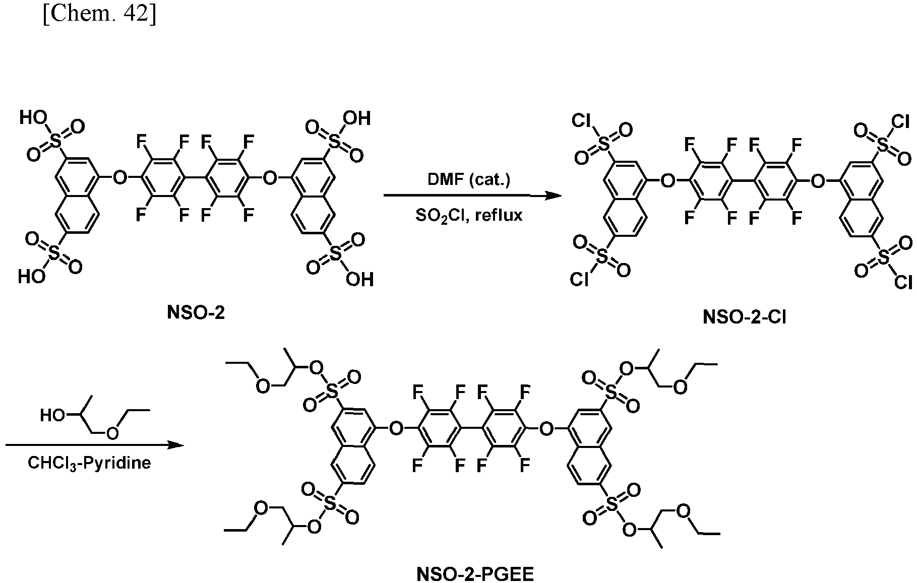
- Thionyl chloride (8 mL) and DMF (85 µL) as a catalyst were added to 2 g (2.2 mmol) of NSO-2 synthesized in accordance with the method described in
WO 2006/025342 , and the system was refluxed under heating for 1 hour, following which the thionyl chloride was driven off, giving a solid containing NSO-2-Cl. This compound was used in the next step without further purification. Chloroform (12 mL) and pyridine (8 mL) were added to the solid, and 2.75 g (26.4 mmol) of propylene glycol monoethyl ether (Junsei Chemical Co., Ltd.) was added at 0°C. The temperature was raised to room temperature and 3 hours of stirring was carried out thereafter. The solvent was driven off, following which water was added, extraction was carried out with ethyl acetate, and the organic layer was dried over sodium sulfate. After filtration and concentration, the resulting crude product was purified by silica gel column chromatography (hexane/ethyl acetate), giving 1.50 g of the sulfonic acid ester compound NSO-2-PGEE (hereinafter, referred to as NSO-2-PGEE-2) as a white solid (yield: 54% (2-step yield from NSO-2)). The results of 1H-NMR and LC/MS measurement are shown below.
1H-NMR (500 MHz, CDCl3): - δ 0.92-0.97 (m, 12H), 1.34 and 1.40 (a pair of d, J = 6.5 Hz, 12H), 3.32-3.52 (m, 16H), 4.80-4.87 (m, 4H), 7.37 (s, 2H), 8.22 (d, J = 8.5 Hz, 2H), 8.45 (s, 2H),
- 8.61 (d, J = 8.5 Hz, 2H), 8.69 (s, 2H).
- The sulfonic acid ester compound 4FNS-4-PGEE was synthesized in accordance with the following scheme.

- 25 g of thionyl chloride and 0.4 mL of DMF as a catalyst were added to 4.97 g (10 mmol) of 4FNS-4 synthesized in accordance with the method described in
WO 2015/111654 , and the system was refluxed under heating for 1 hour, following which the thionyl chloride was driven off, giving a solid containing 4FNS-4-Cl. This compound was used in the next step without further purification. - Chloroform (30 mL) and pyridine (20 mL) were added to the solid, and 6.24 g (60 mmol) of propylene glycol monoethyl ether was added at 0°C. The temperature was raised to room temperature and 1.5 hours of stirring was carried out thereafter. The solvent was driven off, following which water was added, extraction was carried out with ethyl acetate, and the organic layer was dried over sodium sulfate. After filtration and concentration, the resulting crude product was purified by silica gel column chromatography (hexane/ethyl acetate), giving 1.32 g of the sulfonic acid ester compound 4FNS-4-PGEE as a white solid (yield: 20% (2-step yield from 4FNS-4)). The results of 1H-NMR and LC/MS measurement are shown below.
1H-NMR (500 MHz, CDCl3): - δ 0.89-0.95 (m, 6H), 1.34 and 1.39 (a pair of d, J = 6.5 Hz, 6H), 3.28-3.50 (m, 8H), 4.81-4.87 (m, 2H), 7.26 (s, 1H), 8.22 (d, J = 9.0 Hz, 1H), 8.47 (s, 1H),
- 8.54 (d, J = 9.0 Hz, 1H), 8.68 (s, 1H).
- Chloroform (5 g) was added to a mixture of NSO-2-PGEE-1 (12.5 mg) and compound H1 (12.5 mg) of the following formula (H1) which had been synthesized in accordance with the method described
WO 2005/094133 , and the system was dissolved by performing stirring at room temperature, the resulting solution was filtered by a syringe filter having a pore size of 0.2 µm, giving charge-transporting varnish A1.
- Chloroform (5 g) was added to compound H1 (25 mg), the system was dissolved by performing stirring at room temperature, and the resulting solution was filtered by a syringe filter having a pore size of 0.2 µm, giving charge-transporting varnish A2.
- Chloroform (5 g) was added to a mixture of NSO-2-PGEE-1 (12.5 mg) and compound H2 (12.5 mg) of the following formula (H2) which had been synthesized in accordance with the method described
WO 2013/098175 , and the system was dissolved by performing stirring at room temperature, the resulting solution was filtered by a syringe filter having a pore size of 0.2 µm, giving charge-transporting varnish B1.
- Chloroform (5 g) was added to compound H2 (25 mg), the system was dissolved by performing stirring at room temperature, and the resulting solution was filtered by a syringe filter having a pore size of 0.2 µm, giving charge-transporting varnish B2.
- Chloroform (5 g) was added to a mixture of compound H3 (TFB Polymer, from Luminescence Technology Corp., LT-N148) (12.5 mg) of the following formula (H3) and NSO-2-PGEE-1 (12.5 mg), and the system was dissolved by performing stirring at room temperature, the resulting solution was filtered by a syringe filter having a pore size of 0.2 µm, giving charge-transporting varnish C1.

- Chloroform (5 g) was added to compound H3 (25 mg), the system was dissolved by performing stirring at room temperature, and the resulting solution was filtered by a syringe filter having a pore size of 0.2 µm, giving charge-transporting varnish C2.
- Chloroform (5g) was added to a mixture of compound H1 (12.5 mg) and NSO-2 (12.5 mg), and the system was stirred at room temperature at 350 rpm for 60 minutes. NSO-2 was not dissolved.
- Chloroform (5g) was added to a mixture of compound H2 (12.5 mg) and NSO-2 (12.5 mg), and the system was stirred at room temperature at 350 rpm for 60 minutes. NSO-2 was not dissolved.
- Chloroform (5g) was added to a mixture of compound H3 (12.5 mg) and NSO-2 (12.5 mg), and the system was stirred at room temperature at 350 rpm for 60 minutes. NSO-2 was not dissolved.
- Compound H4 (190 mg) of the following formula (H4) which had been synthesized in accordance with the method described in
WO 2015/050253 , Synthesis Example 18, and NSO-2-PGEE-2 (337 mg) were added to a mixed solvent of 3-phenoxytoluene (5 g) and tetralin (5 g), and the system was stirred for 5 minutes under heating at 50°C and 400 rpm. As a result, the NSO-2-PGEE-2 was dissolved completely in the solvent. The resulting solution was filtered using a PTFE filter having a pore size of 0.2 µm, giving charge-transporting varnish D.
- Compound H4 (48 mg), compound H5 (149 mg) of the following formula (H5) which had been synthesized in accordance with the method described in
WO 2015/050253 , Production Example 24-2, and NSO-2-PGEE-2 (329 mg) were added to a mixed solvent of 3-phenoxytoluene (5 g) and tetralin (5 g), and the system was stirred for 5 minutes under heating at 50°C and 400 rpm. As a result, the NSO-2-PGEE-2 was dissolved completely in the solvent. The resulting solution was filtered using a PTFE filter having a pore size of 0.2 µm, giving charge-transporting varnish E.
- Compound H4 (190 mg) and NSO-2-PGEE-2 (337 mg) were added to a mixed solvent of triethylene glycol butyl methyl ether (7 g) and butyl benzoate (3 g), and the system was stirred for 5 minutes under heating at 50°C and 400 rpm. As a result, the NSO-2-PGEE-2 was dissolved completely in the solvent. The resulting solution was filtered using a PTFE filter having a pore size of 0.2 µm, giving charge-transporting varnish F.
- Compound H4 (48 mg), compound H5 (149 mg) and NSO-2-PGEE-2 (329 mg) were added to a mixed solvent of triethylene glycol butyl methyl ether (7 g) and butyl benzoate (3 g), and the system was stirred for 5 minutes under heating at 50°C and 400 rpm. As a result, the NSO-2-PGEE-2 was dissolved completely in the solvent. The resulting solution was filtered using a PTFE filter having a pore size of 0.2 µm, giving charge-transporting varnish G.
- Compound H4 (190 mg) and NSO-2-PGEE-2 (337 mg) were added to a mixed solvent of 4-methoxytoluene (7 g) and cyclohexylbenzene (3 g), and the system was stirred for 5 minutes under heating at 50°C and 400 rpm. As a result, the NSO-2-PGEE-2 was dissolved completely in the solvent. The resulting solution was filtered using a PTFE filter having a pore size of 0.2 µm, giving charge-transporting varnish H.
- Compound H4 (48 mg), compound H5 (149 mg) and NSO-2-PGEE-2 (329 mg) were added to a mixed solvent of 4-methoxytoluene (7 g) and cyclohexylbenzene (3 g), and the system was stirred for 5 minutes under heating at 5°C and 400 rpm. As a result, the NSO-2-PGEE-2 was dissolved completely in the solvent. The resulting solution was filtered using a PTFE filter having a pore size of 0.2 µm, giving charge-transporting varnish I.
- Compound H4 (190 mg) and NSO-2-PGEE-2 (337 mg) were added to a mixed solvent of ethyl benzoate (7 g) and dibenzyl ether (3 g), and the system was stirred for 5 minutes under heating at 50°C and 400 rpm. As a result, the NSO-2-PGEE-2 was dissolved completely in the solvent. The resulting solution was filtered using a PTFE filter having a pore size of 0.2 µm, giving charge-transporting varnish J.
- Compound H4 (48 mg), compound H5 (149 mg) and NSO-2-PGEE-2 (329 mg) were added to a mixed solvent of ethyl benzoate (7 g) and dibenzyl ether (3 g), and the system was stirred for 5 minutes under heating at 50°C and 400 rpm. As a result, the NSO-2-PGEE-2 was dissolved completely in the solvent. The resulting solution was filtered using a PTFE filter having a pore size of 0.2 µm, giving charge-transporting varnish K.
- Compound H4 (270 mg) and 4FNS-4-PGEE (257 mg) were added to a mixed solvent of 3-phenoxytoluene (3 g) and butyl benzoate (7 g), and the system was stirred for 10 minutes under heating at 50°C and 350 rpm. As a result, the 4FNS-4-PGEE was dissolved completely in the solvent. The resulting solution was filtered using a PTFE filter having a pore size of 0.2 µm, giving charge-transporting varnish L.
- Compound H4 (105 mg) and 4FNS-4-PGEE (100 mg) were added to a mixed solvent of diethylene glycol (4 g; dielectric constant: 25.2) and triethylene glycol dimethyl ether (6 g; dielectric constant: 5.1), and the system was stirred for 10 minutes under heating at 50°C and 350 rpm. As a result, the 4FNS-4-PGEE was dissolved completely in the solvent. The resulting solution was filtered using a PTFE filter having a pore size of 0.2 µm, giving charge-transporting varnish M.
- Compound H4 (120 mg) and 4FNS-4 (85 mg) were added to a mixed solvent of diethylene glycol (4 g) and triethylene glycol dimethyl ether (6 g), and the system was stirred for 10 minutes under heating at 50°C and 350 rpm. As a result, the 4FNS-4 was dissolved completely in the solvent. The resulting solution was filtered using a PTFE filter having a pore size of 0.2 µm, giving charge-transporting varnish N.
- Chloroform (5 g) was added to a mixture of compound H3 (25 mg) and methyl p-toluenesulfonate (Tokyo Chemical Industry Co., Ltd.) (38 mg), and the system was dissolved by performing stirring at room temperature, the resulting solution was filtered by a syringe filter having a pore size of 0.2 µm, giving charge-transporting varnish O.
- Chloroform (5 g) was added to a mixture of compound H3 (25 mg) and ethyl benzenesulfonate (Tokyo Chemical Industry Co., Ltd.) (38 mg), and the system was dissolved by performing stirring at room temperature, the resulting solution was filtered by a syringe filter having a pore size of 0.2 µm, giving charge-transporting varnish P.
- In the following Working Examples and Comparative Examples, a glass substrate with dimensions of 25 mm × 25 mm × 0.7 t and having ITO patterned on the surface to a film thickness of 150 nm was used as the ITO substrate. Prior to use, impurities on the surface were removed with an O2 plasma cleaning system (150 W, 30 seconds).
- Charge-transporting varnish A1 was applied onto the ITO substrate using a spin coater, and then subjected to firing at 230°C for 15 minutes, thereby forming a 60-nm thin film on the ITO substrate.
- Using a vapor deposition system (degree of vacuum, 2.0×10⁻⁵ Pa), thin films of aluminum were deposited thereon, giving a single-layer device. Vapor deposition was carried out at a deposition rate of 0.2 nm/s. The thicknesses of the aluminum thin film was set to 80 nm.
- To prevent the device characteristics from deteriorating due to the influence of oxygen, moisture and the like in air, the single-layer device was sealed with sealing substrates, following which the characteristics were evaluated. Sealing was carried out by the following procedure.
- The single-layer device was placed between sealing substrates in a nitrogen atmosphere having an oxygen concentration of 2 ppm or less and a dew point of not more than -85°C, and the sealing substrates were laminated together using an adhesive (MORESCO Moisture Cut WB90US(P), from Moresco Corporation). At this time, a desiccant (HD-071010W-40, from Dynic Corporation) was placed, together with the single-layer device, within the sealing substrates. The laminated sealing substrates were irradiated with an ultraviolet ray (wavelength, 365 nm; dosage, 6,000 mJ/cm2) and then annealed at 80°C for 1 hour to cure the adhesive.
- Except that charge-transporting varnish A2 was used instead of charge-transporting varnish A1, the same procedure as in Example 2-1 was carried out to fabricate a single-layer device.
- Except that charge-transporting varnish B1 was used instead of charge-transporting varnish A1, the same procedure as in Example 2-1 was carried out to fabricate a single-layer device.
- Except that charge-transporting varnish B2 was used instead of charge-transporting varnish A1, the same procedure as in Example 2-1 was carried out to fabricate a single-layer device.
- Except that charge-transporting varnish C1 was used instead of charge-transporting varnish A1, the same procedure as in Example 2-1 was carried out to fabricate a single-layer device.
- Except that charge-transporting varnish C2 was used instead of charge-transporting varnish A1, the same procedure as in Example 2-1 was carried out to fabricate a single-layer device.
- The current densities at a driving voltage of 5 V were measured for the single-layer devices fabricated in Examples 2-1 to 2-3 and Comparative Examples 2-1 to 2-3. The results are shown in Table 1.
[Table 1] Charge-transporting varnish Current density (mA/cm2) Example 2-1 A1 3,250 Comparative Example 2-1 A2 321 Example 2-2 B1 2,706 Comparative Example 2-2 B2 293 Example 2-3 C1 408 Comparative Example 2-3 C2 14 - The ITO substrate used in the following Examples and Comparative Examples was the same as that described above.
- Charge-transporting varnish A1 was applied onto the ITO substrate using a spin coater, and then subjected to firing at 230°C for 15 minutes, thereby forming a 60-nm thin film on the ITO substrate.
- Using a vapor deposition system (degree of vacuum, 2.0 × 10⁻⁵ Pa), thin films of α-NPD and aluminum were successively deposited thereon, giving a hole-only device. Vapor deposition was carried out at a deposition rate of 0.2 nm/s. The thicknesses of the α-NPD thin film and the aluminum thin film were set to respectively 30 nm and 80 nm.
- To prevent the device characteristics from deteriorating due to the influence of oxygen, moisture and the like in air, the hole-only device was sealed with sealing substrates, following which the characteristics were evaluated. Sealing was carried out by the following procedure.
- The hole-only device was placed between sealing substrates in a nitrogen atmosphere having an oxygen concentration of 2 ppm or less and a dew point of not more than -85°C, and the sealing substrates were laminated together using an adhesive (MORESCO Moisture Cut WB90US(P), from Moresco Corporation). At this time, a desiccant (HD-071010W-40, from Dynic Corporation) was placed, together with the hole-only device, within the sealing substrates. The laminated sealing substrates were irradiated with an ultraviolet ray (wavelength, 365 nm; dosage, 6,000 mJ/cm2) and then annealed at 80°C for 1 hour to cure the adhesive.
- Except that charge-transporting varnish A2 was used instead of charge-transporting varnish A1, the same procedure as in Example 3-1 was carried out to fabricate a hole-only device.
- Except that charge-transporting varnish B1 was used instead of charge-transporting varnish A1, the same procedure as in Example 3-1 was carried out to fabricate a hole-only device.
- Except that charge-transporting varnish B2 was used instead of charge-transporting varnish A1, the same procedure as in Example 3-1 was carried out to fabricate a hole-only device.
- Except that charge-transporting varnish C1 was used instead of charge-transporting varnish A1, the same procedure as in Example 3-1 was carried out to fabricate a hole-only device.
- Except that charge-transporting varnish C2 was used instead of charge-transporting varnish A1, the same procedure as in Example 3-1 was carried out to fabricate a hole-only device.
- The current densities at a driving voltage of 5 V were measured for the hole-only devices fabricated in Examples 3-1 to 3-3 and Comparative Examples 3-1 to 3-3. The results are shown in Table 2.
[Table 2] Charge-transporting varnish Current density (mA/cm2) Example 3-1 A1 459 Comparative Example 3-1 A2 9 Example 3-2 B1 4 Comparative Example 3-2 B2 0.06 Example 3-3 C1 39 Comparative Example 3-3 C2 2 - As shown in Tables 1 and 2, the charge-transporting varnish of the invention which contains an aryl sulfonate ester compound had higher electrical conductivity and higher hole-transportability as compared to a charge-transporting varnish which does not contain an aryl sulfonate ester compound.
- The ITO substrate used in the following Examples and Comparative Examples was the same as that described above.
- Charge-transporting varnish D was applied onto the ITO substrate using a spin coater and was subsequently pre-fired at 120°C for 1 minute in open air and then subjected to main firing at 230°C for 15 minutes, thereby forming a 30-nm hole-injecting layer thin film on the ITO substrate.
- Next, in a glove box under a nitrogen atmosphere, a 0.6 wt% xylene solution of TFB polymer (LT-N148, from Luminescence Technology) was spin-coated onto the hole-injecting layer to form a film, and heating and baking at 130°C was carried out for 10 minutes, thereby forming a 40-nm hole-transporting layer thin-film.
- Using a vapor deposition system (degree of vacuum, 2.0×10⁻⁵ Pa), thin films of aluminum were deposited thereon, giving a hole-only device. Vapor deposition was carried out at a deposition rate of 0.2 nm/s. The thicknesses of the aluminum thin film was set to 80 nm.
- To prevent the device characteristics from deteriorating due to the influence of oxygen, moisture and the like in air, the hole-only device was sealed with sealing substrates, following which the characteristics were evaluated. Sealing was carried out by the following procedure.
- The hole-only device was placed between sealing substrates in a nitrogen atmosphere having an oxygen concentration of 2 ppm or less and a dew point of not more than -85°C, and the sealing substrates were laminated together using an adhesive (MORESCO Moisture Cut WB90US(P), from Moresco Corporation). At this time, a desiccant (HD-071010W-40, from Dynic Corporation) was placed, together with the hole-only device, within the sealing substrates. The laminated sealing substrates were irradiated with an ultraviolet ray (wavelength, 365 nm; dosage, 6,000 mJ/cm2) and then annealed at 80°C for 1 hour to cure the adhesive.
- Except that charge-transporting varnish E was used instead of charge-transporting varnish D, the same procedure as in Example 4-1 was carried out to fabricate a hole-only device.
- Except that charge-transporting varnish F was used instead of charge-transporting varnish D, the same procedure as in Example 4-1 was carried out to fabricate a hole-only device.
- Except that charge-transporting varnish G was used instead of charge-transporting varnish D, the same procedure as in Example 4-1 was carried out to fabricate a hole-only device.
- Except that charge-transporting varnish H was used instead of charge-transporting varnish D, the same procedure as in Example 4-1 was carried out to fabricate a hole-only device.
- Except that charge-transporting varnish I was used instead of charge-transporting varnish D, the same procedure as in Example 4-1 was carried out to fabricate a hole-only device.
- Except that charge-transporting varnish J was used instead of charge-transporting varnish D, the same procedure as in Example 4-1 was carried out to fabricate a hole-only device.
- Except that charge-transporting varnish K was used instead of charge-transporting varnish D, the same procedure as in Example 4-1 was carried out to fabricate a hole-only device.
- Except that a hole-injecting layer was not formed, the same procedure as in Example 4-1 was carried out to fabricate a hole-only device.
- The current densities at a driving voltage of 5 V were measured for the hole-only devices fabricated in Examples 4-1 to 4-8 and Comparative Example 4-1. The results are shown in Table 3.
[Table 3] Charge-transporting varnish Current density (mA/cm2) Example 4-1 D 1,840 Example 4-2 E 2,025 Example 4-3 F 2,188 Example 4-4 G 1,725 Example 4-5 H 2,167 Example 4-6 I 2,115 Example 4-7 J 2,240 Example 4-8 K 1,628 Comparative Example 4-1 - 49 - As shown in Table 3, a charge-transporting varnish containing the sulfonic acid ester compound of the invention had high hole-transportability.
- The ITO substrate used in the following Examples and Comparative Examples was the same as that described above.
- Charge-transporting varnish L was applied onto the ITO substrate using a spin coater and was subsequently pre-fired at 120°C for 1 minute in open air and then subjected to main firing at 230°C for 15 minutes, thereby forming a 40-nm thin film on the ITO substrate.
- Using a vapor deposition system (degree of vacuum, 2.0×10⁻⁵ Pa), thin films of α-NPD and aluminum were successively deposited thereon, giving a hole-only device. Vapor deposition was carried out at a deposition rate of 0.2 nm/s. The thicknesses of the α-NPD thin film and the aluminum thin film were set to respectively 30 nm and 80 nm.
- To prevent the device characteristics from deteriorating due to the influence of oxygen, moisture and the like in air, the hole-only device was sealed with sealing substrates, following which the characteristics were evaluated. Sealing was carried out by the following procedure.
- The hole-only device was placed between sealing substrates in a nitrogen atmosphere having an oxygen concentration of 2 ppm or less and a dew point of not more than -85°C, and the sealing substrates were laminated together using an adhesive (MORESCO Moisture Cut WB90US(P), from Moresco Corporation). At this time, a desiccant (HD-071010W-40, from Dynic Corporation) was placed, together with the hole-only device, within the sealing substrates. The laminated sealing substrates were irradiated with an ultraviolet ray (wavelength, 365 nm; dosage, 6,000 mJ/cm2) and then annealed at 80°C for 1 hour to cure the adhesive.
- Except that charge-transporting varnish M was used instead of charge-transporting varnish L, the same procedure as in Example 5-1 was carried out to fabricate a hole-only device.
- Except that charge-transporting varnish N was used instead of charge-transporting varnish L, the same procedure as in Example 5-1 was carried out to fabricate a hole-only device.
- The current densities at a driving voltage of 4 V were measured for the hole-only devices fabricated in Examples 5-1 to 5-2 and Comparative Example 5-1. The results are shown in Table 4.
[Table 4] Charge-transporting varnish Current density (mA/cm2) Example 5-1 L 2,370 Example 5-2 M 2,086 Comparative Example 5-1 N 97 - As shown in Table 4, a charge-transporting varnish containing the sulfonic acid ester compound of the invention had higher hole-transportability as compared to a charge-transporting varnish containing a conventional sulfonic acid ester compound.
- Charge-transporting varnish A1 was applied onto the ITO substrate using a spin coater, and then subjected to firing at 230°C for 15 minutes, thereby forming a 60-nm thin film on the ITO substrate.
- Using a vapor deposition system (degree of vacuum: 2.0×10⁻⁵ Pa), α-NPD of 30 nm and Alq3 of 40 nm were successively deposited thereon. At this time, the vapor deposition was carried out at a deposition rate of 0.2 nm/sec. Subsequently, thin films of lithium fluoride and aluminum were successively deposited, giving an organic EL device. At this time, the vapor deposition was carried out at a rate of 0.02 nm/sec for lithium fluoride and, at a rate of 0.2 nm/sec for aluminum. The thicknesses of the lithium fluoride thin film and the aluminum thin film were set to respectively 0.5 nm and 80 nm.
- To prevent the device characteristics from deteriorating due to the influence of oxygen, moisture and the like in air, the organic EL device was sealed with sealing substrates, following which the characteristics were evaluated. Sealing was carried out by the following procedure.
- The organic EL device was placed between sealing substrates in a nitrogen atmosphere having an oxygen concentration of 2 ppm or less and a dew point of not more than -85°C, and the sealing substrates were laminated together using an adhesive (MORESCO Moisture Cut WB90US(P), from Moresco Corporation). At this time, a desiccant (HD-071010W-40, from Dynic Corporation) was placed, together with the organic EL device, within the sealing substrates. The laminated sealing substrates were irradiated with an ultraviolet ray (wavelength, 365 nm; dosage, 6,000 mJ/cm2) and then annealed at 80°C for 1 hour to cure the adhesive.
- Except that charge-transporting varnish A2 was used instead of charge-transporting varnish A1, the same procedure as in Example 6-1 was carried out to fabricate an organic EL device.
- Except that charge-transporting varnish B1 was used instead of charge-transporting varnish A1, the same procedure as in Example 6-1 was carried out to fabricate an organic EL device.
- Except that charge-transporting varnish B2 was used instead of charge-transporting varnish A1, the same procedure as in Example 6-1 was carried out to fabricate an organic EL device.
- Except that charge-transporting varnish C1 was used instead of charge-transporting varnish A1, the same procedure as in Example 6-1 was carried out to fabricate an organic EL device.
- Except that charge-transporting varnish O was used instead of charge-transporting varnish A1, the same procedure as in Example 6-1 was carried out to fabricate an organic EL device.
- Except that charge-transporting varnish P was used instead of charge-transporting varnish A1, the same procedure as in Example 6-1 was carried out to fabricate an organic EL device.
- Except that charge-transporting varnish C2 was used instead of charge-transporting varnish A1, the same procedure as in Example 6-1 was carried out to fabricate an organic EL device.
- The current densities and the luminances at a predetermined driving voltage were measured for the organic EL devices fabricated in Examples 6-1 to 6-5 and Comparative Examples 6-1 to 6-3. The results are shown in Table 5.
[Table 5] Charge-transporting varnish Driving voltage (V) Current density (mA/cm2) Luminance (cd/m2) Example 6-1 A1 6 18.1 794 Comparative Example 6-1 A2 6 1.1 20 Example 6-2 B1 7 153 346 Comparative Example 6-2 B2 7 1.1×10⁻² 0.28 Example 6-3 C1 10 31.3 148 Example 6-4 O 10 3.3 85 Example 6-5 P 10 1.0 19 Comparative Example 6-3 C2 10 4.7×10⁻² 6.8×10⁻² - As shown in Table 5, the charge-transporting varnish of the invention which contains an aryl sulfonate ester compound had higher organic EL characteristics as compared to a charge-transporting varnish which does not contain an aryl sulfonate ester compound.
Claims (9)
- A charge-transporting varnish comprising: (A) an aryl sulfonate ester compound; (B) a tertiary aryl amine compound having at least one nitrogen atom with all the nitrogen atoms forming a tertiary aryl amine structure; and (C) an organic solvent.
- The charge-transporting varnish according to claim 1, wherein the aryl sulfonate ester compound is a fluorine atom-containing aryl sulfonate ester compound.
- The charge-transporting varnish according to claim 1, wherein the aryl sulfonate ester compound is a compound of the following formula (1) or (1'):

 wherein W1 and W2 are each independently -O-, -S-, -S (O)- or -S(O2)-, or -N-, Si-, -P- or -P(O)- which optionally has a substituent;A2 is -O-, -S- or -NH-;A3 is an (n+1)-valent aromatic group of 6 to 20 carbon atoms;X1 is an alkylene group of 2 to 5 carbon atoms, the alkylene group optionally having -O-, -S- or a carbonyl group interposed between carbon atoms, the alkylene group being optionally substituted with alkyl groups of 1 to 20 carbon atoms at some or all of hydrogen atoms;X2 is a single bond, -O-, -S- or -NR-, where R is a hydrogen atom or a monovalent hydrocarbon group of 1 to 10 carbon atoms;X3 is a monovalent hydrocarbon group of 1 to 20 carbon atoms which optionally has a substituent;m is an integer that satisfies the condition 1 ≤ m ≤ 4; andn is an integer that satisfies the condition 1 ≤ n ≤ 4.
 - The charge-transporting varnish according to claim 3, wherein A1 is an m-valent hydrocarbon group of 6 to 20 carbon atoms which is substituted with a fluorine atom, and contains one or more aromatic rings, or an m-valent group derived from a compound of formula (2) or (3).
- The charge-transporting varnish according to any one of claims 1 to 4, wherein the aryl sulfonate ester compound is a compound of any one of the following formulas (1-1) to (1-3):
 wherein Rs1 to Rs4 are each independently a hydrogen atom or a linear or branched alkyl group of 1 to 6 carbon atoms, and Rs5 is a monovalent hydrocarbon group of 2 to 20 carbon atoms which optionally has a substituent;A11 is an m-valent group derived from perfluorobiphenyl, A12 is -O- or -S-, and A13 is an (n+1)-valent group derived from naphthalene or anthracene; andm and n are the same as described above;
 wherein Rs6 and Rs7 are each independently a hydrogen atom, or a linear or branched monovalent aliphatic hydrocarbon group, and Rs8 is a linear or branched monovalent aliphatic hydrocarbon group, provided that the total number of carbon atoms of Rs6, Rs7 and Rs8 is 6 or more;A14 is an m-valent hydrocarbon group which optionally has a substituent and which contains one or more aromatic rings, A15 is -O- or -S-, and A16 is an (n+1)-valent aromatic group; andm and n are the same as described above; and
 wherein Rs9 to Rs13 are each independently a hydrogen atom, a nitro group, a cyano group, a halogen atom, an alkyl group of 1 to 10 carbon atoms, a halogenated alkyl group of 1 to 10 carbon atoms, or a halogenated alkenyl group of 2 to 10 carbon atoms;Rs14 to Rs17 are each independently a hydrogen atom, or a linear or branched monovalent aliphatic hydrocarbon group of 1 to 20 carbon atoms;Rs18 is a linear or branched monovalent aliphatic hydrocarbon group of 1 to 20 carbon atoms, or -ORs19, where Rs19 is a monovalent hydrocarbon group of 2 to 20 carbon atoms which optionally has a substituent;A17 is -O-, -S- or -NH-;A18 is an (n+1)-valent aromatic group; andn is the same as described above.
 - The charge-transporting varnish according to any one of claims 1 to 5, wherein the tertiary aryl amine compound has at least two nitrogen atoms, with all the nitrogen atoms forming a tertiary aryl amine structure.
- The charge-transporting varnish according to any one of claims 1 to 6, wherein the organic solvent is a low-polarity organic solvent.
- A charge-transporting thin film obtained using the charge-transporting varnish according to any one of claims 1 to 7.
- An organic electroluminescence device comprising the charge-transporting thin film according to claim 8.
Applications Claiming Priority (2)
| Application Number | Priority Date | Filing Date | Title |
|---|---|---|---|
| JP2017243550 | 2017-12-20 | ||
| PCT/JP2018/046693 WO2019124415A1 (en) | 2017-12-20 | 2018-12-19 | Charge-transporting varnish |
Publications (2)
| Publication Number | Publication Date |
|---|---|
| EP3731290A1 true EP3731290A1 (en) | 2020-10-28 |
| EP3731290A4 EP3731290A4 (en) | 2021-09-29 |
Family
ID=66994007
Family Applications (1)
| Application Number | Title | Priority Date | Filing Date |
|---|---|---|---|
| EP18890018.7A Withdrawn EP3731290A4 (en) | 2017-12-20 | 2018-12-19 | CARGO TRANSPORT PAINT |
Country Status (7)
| Country | Link |
|---|---|
| US (1) | US20210078934A1 (en) |
| EP (1) | EP3731290A4 (en) |
| JP (1) | JP7310609B2 (en) |
| KR (1) | KR102861459B1 (en) |
| CN (1) | CN111512459A (en) |
| TW (1) | TWI808111B (en) |
| WO (1) | WO2019124415A1 (en) |
Cited By (2)
| Publication number | Priority date | Publication date | Assignee | Title |
|---|---|---|---|---|
| US11404642B2 (en) | 2018-04-24 | 2022-08-02 | Samsung Display Co., Ltd. | Organic light-emitting device and method of manufacturing the same |
| US12344602B2 (en) | 2018-11-16 | 2025-07-01 | Semiconductor Energy Laboratory Co., Ltd. | Organic compound, EL device, light-emitting apparatus, electronic appliance, lighting device, and electronic device |
Families Citing this family (2)
| Publication number | Priority date | Publication date | Assignee | Title |
|---|---|---|---|---|
| EP3960730A4 (en) * | 2019-04-26 | 2023-02-08 | Nissan Chemical Corporation | METHOD FOR PRODUCING AN ARYLSULPHONIC ACID ESTER COMPOUND |
| CN114105838A (en) * | 2021-11-19 | 2022-03-01 | 北京大学深圳研究生院 | Flexible thermoelectric material and preparation method thereof |
Family Cites Families (33)
| Publication number | Priority date | Publication date | Assignee | Title |
|---|---|---|---|---|
| JPS5136795B2 (en) | 1971-11-12 | 1976-10-12 | ||
| JPS52111253A (en) | 1976-03-13 | 1977-09-17 | Showa Ooto Kk | Automatic door |
| US5834100A (en) * | 1996-06-25 | 1998-11-10 | Northwestern University | Organic light-emitting dioddes and methods for assembly and emission control |
| TW200504046A (en) * | 2003-06-25 | 2005-02-01 | Nissan Chemical Ind Ltd | 1,4-Benzodioxane sulfonic acid compound and use thereof as electron-acceptor material |
| KR100882172B1 (en) | 2004-03-11 | 2009-02-06 | 미쓰비시 가가꾸 가부시키가이샤 | Composition and ion compound for charge transport film, charge transport film and organic electroluminescent device using same, method for manufacturing organic electroluminescent device and method for manufacturing charge transport film |
| CN100505966C (en) | 2004-03-25 | 2009-06-24 | 保土谷化学工业株式会社 | Arylamine compound and organic electroluminescent device |
| EP1785413B1 (en) * | 2004-08-31 | 2014-01-22 | Nissan Chemical Industries, Ltd. | Arylsulfonic acid compound and use thereof as electron-acceptor material |
| US20070077452A1 (en) * | 2005-10-04 | 2007-04-05 | Jie Liu | Organic light emitting devices having latent activated layers and methods of fabricating the same |
| JP4977998B2 (en) * | 2005-11-16 | 2012-07-18 | 富士ゼロックス株式会社 | Charge transporting compound, charge transporting film and electroluminescent device using the same |
| WO2007099808A1 (en) * | 2006-02-23 | 2007-09-07 | Nissan Chemical Industries, Ltd. | Sulfonic acid ester compound and use thereof |
| WO2008032616A1 (en) | 2006-09-13 | 2008-03-20 | Nissan Chemical Industries, Ltd. | Oligoaniline compounds |
| US8298444B2 (en) * | 2007-04-12 | 2012-10-30 | Nissan Chemical Industries, Ltd. | Oligoaniline compound |
| JP5287455B2 (en) | 2008-04-16 | 2013-09-11 | 三菱化学株式会社 | Hole injection transport layer forming composition, method for manufacturing hole injection transport layer forming composition, organic electroluminescence device, organic EL display, and organic EL lighting |
| WO2010058777A1 (en) | 2008-11-19 | 2010-05-27 | 日産化学工業株式会社 | Charge transporting material and charge transporting varnish |
| JP2011022509A (en) * | 2009-07-17 | 2011-02-03 | Fujifilm Corp | Positive photosensitive resin composition for organic insulating film, organic insulating film, organic el display device and liquid crystal display device |
| KR20140108701A (en) | 2010-04-22 | 2014-09-12 | 히타치가세이가부시끼가이샤 | Organic electronic material, polymerization initiator and thermal polymerization initiator, ink composition, organic thin film and production method for same, organic electronic element, organic electroluminescent element, lighting device, display element, and display device |
| JP5994213B2 (en) | 2011-05-31 | 2016-09-21 | 日立化成株式会社 | Electron-accepting compound and method for producing the same, polymerization initiator containing the compound, organic electronics material, organic thin film, organic electronics element, organic electroluminescent element, display element, lighting device, and display apparatus using the same |
| DE102011104745A1 (en) | 2011-06-17 | 2012-12-20 | Merck Patent Gmbh | Materials for organic electroluminescent devices |
| KR101641674B1 (en) * | 2011-09-21 | 2016-07-21 | 닛산 가가쿠 고교 가부시키 가이샤 | Charge-transporting varnish |
| EP2610240A1 (en) | 2011-12-28 | 2013-07-03 | Solvay Sa | Crosslinkable arylamine compounds |
| WO2014073683A1 (en) | 2012-11-12 | 2014-05-15 | 三菱化学株式会社 | Organic electroluminescent element and method for manufacturing same |
| CN105392771B (en) * | 2013-05-20 | 2019-01-15 | 日产化学工业株式会社 | Triphenylamine derivative and its utilization |
| WO2015050253A1 (en) * | 2013-10-04 | 2015-04-09 | 日産化学工業株式会社 | Aniline derivatives and uses thereof |
| WO2015111654A1 (en) | 2014-01-27 | 2015-07-30 | 日産化学工業株式会社 | Aryl sulfonic acid compound and use of same |
| EP3109914B1 (en) * | 2014-02-18 | 2021-04-28 | Nissan Chemical Corporation | Charge-transporting varnish |
| EP3124466A4 (en) * | 2014-03-27 | 2017-11-08 | Nissan Chemical Industries, Ltd. | Triarylamine derivative and use of same |
| US11018303B2 (en) * | 2014-06-05 | 2021-05-25 | Nissan Chemical Industries, Ltd. | Charge-transporting varnish |
| TWI671327B (en) | 2014-07-10 | 2019-09-11 | 日商日產化學工業股份有限公司 | Polymer containing fluorine atom and its utilization |
| CN107210378B (en) * | 2015-01-21 | 2019-11-26 | 日产化学工业株式会社 | Charge-transporting varnish, charge-transporting film and organic electroluminescent device |
| WO2016190326A1 (en) * | 2015-05-27 | 2016-12-01 | 日産化学工業株式会社 | Charge-transporting varnish, and organic electroluminescent element |
| JP6443587B2 (en) * | 2016-06-16 | 2018-12-26 | 日産化学株式会社 | Sulfonic acid ester compounds and use thereof |
| KR102392403B1 (en) * | 2016-06-16 | 2022-04-29 | 닛산 가가쿠 가부시키가이샤 | Sulfonic acid ester compounds and their use |
| CN107118206A (en) * | 2017-04-07 | 2017-09-01 | 同济大学 | The pyridine derivate Zn of one class quinoline two2+Fluorescence probe and its application |
-
2018
- 2018-12-19 EP EP18890018.7A patent/EP3731290A4/en not_active Withdrawn
- 2018-12-19 TW TW107145812A patent/TWI808111B/en active
- 2018-12-19 KR KR1020207020935A patent/KR102861459B1/en active Active
- 2018-12-19 JP JP2019560518A patent/JP7310609B2/en active Active
- 2018-12-19 CN CN201880082195.5A patent/CN111512459A/en active Pending
- 2018-12-19 US US16/956,234 patent/US20210078934A1/en not_active Abandoned
- 2018-12-19 WO PCT/JP2018/046693 patent/WO2019124415A1/en not_active Ceased
Cited By (3)
| Publication number | Priority date | Publication date | Assignee | Title |
|---|---|---|---|---|
| US11404642B2 (en) | 2018-04-24 | 2022-08-02 | Samsung Display Co., Ltd. | Organic light-emitting device and method of manufacturing the same |
| EP3561896B1 (en) * | 2018-04-24 | 2025-02-26 | Samsung Display Co., Ltd. | Organic light-emitting device and method of manufacturing the same |
| US12344602B2 (en) | 2018-11-16 | 2025-07-01 | Semiconductor Energy Laboratory Co., Ltd. | Organic compound, EL device, light-emitting apparatus, electronic appliance, lighting device, and electronic device |
Also Published As
| Publication number | Publication date |
|---|---|
| CN111512459A (en) | 2020-08-07 |
| KR102861459B1 (en) | 2025-09-18 |
| EP3731290A4 (en) | 2021-09-29 |
| TW201939782A (en) | 2019-10-01 |
| KR20200098661A (en) | 2020-08-20 |
| WO2019124415A1 (en) | 2019-06-27 |
| US20210078934A1 (en) | 2021-03-18 |
| JP7310609B2 (en) | 2023-07-19 |
| JPWO2019124415A1 (en) | 2020-12-24 |
| TWI808111B (en) | 2023-07-11 |
Similar Documents
| Publication | Publication Date | Title |
|---|---|---|
| US10513491B2 (en) | Sulfonic acid ester compound and use therefor | |
| US10847725B2 (en) | Sulfonic acid ester compound and use therefor | |
| EP3154100A1 (en) | Charge-transporting varnish | |
| EP3434666A1 (en) | Arylamine derivative and use thereof | |
| JP7310609B2 (en) | charge transport varnish | |
| JP6947180B2 (en) | Varnish for forming charge-transporting thin films | |
| EP3124468B1 (en) | Fluorene derivative and use thereof | |
| EP3249710B1 (en) | Charge-transporting varnish, charge-transporting film, and organic electroluminescent element | |
| EP3101003B1 (en) | Aryl sulfonic acid compound and use thereof | |
| EP3101002B1 (en) | Aryl sulfonic acid compound and use of same | |
| JP7234937B2 (en) | Sulfonic acid ester compound and its use | |
| EP3168889B1 (en) | Charge-transporting varnish, charge-transporting thin film and method for manufacturing same, and organic electroluminescent element and method for manufacturing same | |
| EP3000804A1 (en) | Triphenylamine derivative and use therefor | |
| EP3012245B1 (en) | Aniline derivative, charge-transporting varnish and organic electroluminescent device | |
| EP3819956A1 (en) | Composition for forming charge-transporting thin film | |
| EP3766887A1 (en) | Aniline derivative and use thereof | |
| WO2020203594A1 (en) | Fluorene derivative and use thereof | |
| EP3056484A1 (en) | Arylsulfonic acid compound, use thereof, and method for producing arylsulfonic acid compound | |
| WO2018173801A1 (en) | Fluorine-atom-containing polymer and use thereof |
Legal Events
| Date | Code | Title | Description |
|---|---|---|---|
| STAA | Information on the status of an ep patent application or granted ep patent |
Free format text: STATUS: THE INTERNATIONAL PUBLICATION HAS BEEN MADE |
|
| PUAI | Public reference made under article 153(3) epc to a published international application that has entered the european phase |
Free format text: ORIGINAL CODE: 0009012 |
|
| STAA | Information on the status of an ep patent application or granted ep patent |
Free format text: STATUS: REQUEST FOR EXAMINATION WAS MADE |
|
| 17P | Request for examination filed |
Effective date: 20200702 |
|
| AK | Designated contracting states |
Kind code of ref document: A1 Designated state(s): AL AT BE BG CH CY CZ DE DK EE ES FI FR GB GR HR HU IE IS IT LI LT LU LV MC MK MT NL NO PL PT RO RS SE SI SK SM TR |
|
| AX | Request for extension of the european patent |
Extension state: BA ME |
|
| DAV | Request for validation of the european patent (deleted) | ||
| DAX | Request for extension of the european patent (deleted) | ||
| A4 | Supplementary search report drawn up and despatched |
Effective date: 20210826 |
|
| RIC1 | Information provided on ipc code assigned before grant |
Ipc: C09D 7/63 20180101ALI20210820BHEP Ipc: C09D 5/24 20060101ALI20210820BHEP Ipc: C07C 211/61 20060101ALI20210820BHEP Ipc: C07C 211/54 20060101ALI20210820BHEP Ipc: H01L 51/54 20060101AFI20210820BHEP |
|
| STAA | Information on the status of an ep patent application or granted ep patent |
Free format text: STATUS: THE APPLICATION HAS BEEN WITHDRAWN |
|
| 18W | Application withdrawn |
Effective date: 20211110 |