EP3729968B1 - Transportvorrichtung zum transportieren von entweideten geflügelkörpern oder teilen davon - Google Patents
Transportvorrichtung zum transportieren von entweideten geflügelkörpern oder teilen davon Download PDFInfo
- Publication number
- EP3729968B1 EP3729968B1 EP19171118.3A EP19171118A EP3729968B1 EP 3729968 B1 EP3729968 B1 EP 3729968B1 EP 19171118 A EP19171118 A EP 19171118A EP 3729968 B1 EP3729968 B1 EP 3729968B1
- Authority
- EP
- European Patent Office
- Prior art keywords
- transport
- latching
- latching lever
- magnetic element
- lever
- Prior art date
- Legal status (The legal status is an assumption and is not a legal conclusion. Google has not performed a legal analysis and makes no representation as to the accuracy of the status listed.)
- Active
Links
Images


Classifications
-
- A—HUMAN NECESSITIES
- A22—BUTCHERING; MEAT TREATMENT; PROCESSING POULTRY OR FISH
- A22C—PROCESSING MEAT, POULTRY, OR FISH
- A22C21/00—Processing poultry
- A22C21/0053—Transferring or conveying devices for poultry
-
- A—HUMAN NECESSITIES
- A22—BUTCHERING; MEAT TREATMENT; PROCESSING POULTRY OR FISH
- A22B—SLAUGHTERING
- A22B7/00—Slaughterhouse arrangements
- A22B7/001—Conveying arrangements
-
- A—HUMAN NECESSITIES
- A22—BUTCHERING; MEAT TREATMENT; PROCESSING POULTRY OR FISH
- A22B—SLAUGHTERING
- A22B7/00—Slaughterhouse arrangements
- A22B7/001—Conveying arrangements
- A22B7/003—Positioning, orienting or supporting carcasses as they are being conveyed
-
- A—HUMAN NECESSITIES
- A22—BUTCHERING; MEAT TREATMENT; PROCESSING POULTRY OR FISH
- A22C—PROCESSING MEAT, POULTRY, OR FISH
- A22C21/00—Processing poultry
- A22C21/0007—Poultry shackles
-
- A—HUMAN NECESSITIES
- A22—BUTCHERING; MEAT TREATMENT; PROCESSING POULTRY OR FISH
- A22C—PROCESSING MEAT, POULTRY, OR FISH
- A22C21/00—Processing poultry
- A22C21/0046—Support devices
Definitions
- the invention relates to a transport device, designed and set up for transporting divested poultry carcasses or parts thereof in the transport direction T along a transport path along which different processing stations can be arranged, comprising an endlessly rotating transport unit and at least one transport saddle attached to it for holding and positioning the poultry carcasses or parts thereof during transport, with a holding device being provided for fastening the transport saddle to the transport unit, which consists of a receiving body assigned to the transport unit and a fastening body assigned to the transport saddle, which is detachably connected to the receiving body and rotatably mounted in the receiving body about an axis of rotation D.
- the holding device comprises a latching device, by means of which the fastening body and thus the transport saddle in at least two different latching positions ions can be locked
- the locking device comprising a locking lever and at least two locking bolts, the locking lever being arranged on a base body of the receiving body so as to be pivotable about a pivot axis S, which is aligned parallel to the axis of rotation D, and from a locking position in which the locking lever is connected to a Locking bolt, which is assigned to the fastening body, is engaged in a release position in which the locking lever is out of engagement with a locking bolt of the fastening body, and can be moved back
- the transport device having a first actuating member for actuating the locking lever at least from the locking position into the Release position and a second actuating member for rotating the fastening body in the release position of the locking lever.
- Such transport devices are used in the food processing industry to carry products to be processed along the transport path to bring different processing stations into engagement (cf. WO 2015/065190 A1 ). During processing, the products must be fixed in a defined position.
- every transport saddle is therefore in its locked position.
- This means that the locking lever is in engagement with the fastening body and thereby prevents the transport saddle from rotating.
- the products located on the transport saddle have to be positioned for different processing steps, however, in some cases in different orientations in relation to the processing stations.
- the lock In order to move the transport saddle and thus the saddled-on products or parts thereof into a different position, on the one hand the lock has to be released and on the other hand the transport saddle has to be rotated.
- the actuators are arranged accordingly. By contact of the actuating member for actuating the locking lever with the same, this is pivoted about the pivot axis S out of engagement with the locking bolt located on the fastening body into the release position.
- This release position is held until the downstream actuating member for rotating the fastening body is in engagement or in operative connection with it.
- the fastening body is rotated until the latching lever engages with the next following latching bolt of the fastening body.
- the locking lever of the locking device is spring-actuated.
- a spring is arranged on the receiving body which basically holds the latching lever in the locking position, the spring being essentially relaxed in the locking position. This means that only a small force acts in the locking position.
- the spring pulls the latching lever quasi into the locking position in which the latching lever is in a latching position with a latching bolt of the fastening body.
- the highest spring force of the spring of the latching device acts in the release position, while the lowest spring force acts in the locking position.
- the latching lever is only held in the locking position with a small force.
- the repeated movement of the detent lever from the detent position into the release position has a wear-promoting effect due to the force resistances that act and, above all, increase, so that the service life of the springs is limited.
- a spring solution or the associated spring requires more installation space and is difficult to clean due to the uneven surface structure.
- the invention is therefore based on the object of proposing a transport device with a compact and easy-to-clean latching device that ensures safe and low-wear positioning of the transport saddles and locking them in the locking position.
- a transport device characterized in that the locking device comprises at least two magnetic elements, a first magnetic element being assigned to the receiving body and a second magnetic element being assigned to the locking lever, such that unlike poles of the first magnetic Element and the second magnetic element for pulling the detent lever into the locking position oppose each other attractively. Because the spring solution is replaced by a magnet solution, a long-lasting and easy-to-clean latching device for the transport device is created in a simple manner.
- the technical effect that the greatest (holding) force of the latching device exists in the locking position is particularly advantageous, which leads to a particularly safe and precise positioning of the transport saddles, and a lower and, above all, decreasing one Force in the release position, which means that there is less mechanical stress on the locking device.
- the locking device comprises a third magnetic element which is assigned to the receiving body and is placed on the side of the locking lever opposite the first magnetic element, in such a way that poles of the same name of the second magnetic element and the third magnetic element face each other in a repulsive manner to press the locking lever into the locking position.
- the first and second magnetic elements ensure that the locking lever is securely held in the locking position.
- the third magnetic element ensures that the locking lever is pressed reliably and quickly from the release position back into the locking position. This optimizes the reliable functionality of the latching device.
- the base body of the receiving body has, at its end trailing in the transport direction T, on the side facing the fastening body, a recess into which the latching lever with a projection dips at least in sections, the first magnetic element in the recess of the base body in the area of a Rear wall and the second magnetic element is positioned in the projection of the locking lever.
- the third magnetic element is advantageously positioned in the recess of the base body in the area of a side wall such that the latching lever with its projection, in which the second magnetic element is located, is sandwiched between the first and the third magnetic element.
- the serial arrangement of the magnetic elements ensures, on the one hand, that the latching lever is pulled for secure locking and, on the other hand, that the latching lever is reliably pushed out of the release position back into the locking position. Furthermore, this arrangement enables a space-saving and thus space-reducing design of the latching device.
- the base body has an opening in the area of the recess, the main orientation of which is parallel to the pivot axis S and the axis of rotation D, in such a way that the free end of the projection of the locking lever dips into this opening at least in sections, in such a way that that a side wall of the opening is designed in addition to the locking bolt as a stop for the locking lever in its locking position.
- the base body has a circumferential opening delimited by side walls transversely to the transport direction T, one side wall, namely the side wall trailing in the transport direction T, forming a stop or contact surface for the projection of the locking lever. This increases the stability of the locking device.
- the fastening body is assigned a rotating body in the form of a Maltese cross, which on the one hand has four recesses arranged offset from one another in the area of the circumference by 90 ° for engaging the actuating member to rotate the fastening body and, on the other hand, at least four by 90 ° on the side facing the receiving body has latching bolts which are offset from one another and which can be brought into operative connection with the latching lever.
- the locking lever advantageously has a recess for receiving a locking bolt on its inside facing the axis of rotation D.
- the inside has an arcuate course overall, the arcuate course being interrupted by the recess.
- the size of the recess is adapted to the locking pin.
- the locking bolt lies in the recess so that the fastening body is prevented from rotating.
- the fastening body can be rotated, with a subsequent latching bolt sliding on the arcuate inside of the latching lever during rotation until the latching bolt "snaps" into the recess again. This ensures a particularly simple and yet particularly secure twisting and locking.
- the transport unit preferably comprises a transport chain and there is at least one guide rail at least in sections along the transport chain arranged on which the receiving body of the holding device is guided with a groove formed in the base body. This ensures that the transport chain runs smoothly and that the transport saddles are precisely positioned.
- two spaced apart guide rails are arranged at least in sections along the transport chain, between which the base body is guided with corresponding grooves, the actuating member for actuating the latching lever being arranged on one guide rail and the actuating member for rotating the fastening body on the other guide rail is.
- the actuating element for rotating the fastening body in the transport direction T of the transport unit is expediently arranged behind the actuating element for actuating the latching lever. This ensures a particularly simple structure of the transport device.
- An advantageous embodiment is characterized in that the latching lever protrudes with an actuating lug over the base body of the receiving body, such that the actuating element for actuating the latching lever comes into operative connection with the actuating lug of the latching lever when passing the transport saddle.
- the magnetic elements are advantageously designed at least partially as bar magnets, the bar magnets being aligned with their longitudinal axis in the transport direction T. In this way, a space-saving arrangement of the magnetic elements is ensured, in which poles of different names face one another between the first and the second magnetic element, while poles of the same name face one another between the second and the third magnetic element.
- the bar magnets are at least partially arranged in blind holes, the open sides of the blind holes being closed by means of a cover in such a way that those located inside the blind holes Bar magnets are completely shielded from the environment. Because the bar magnets are arranged in closed pockets, the bar magnets are protected against contamination and smooth surfaces are created that are particularly easy to clean.
- the transport device shown only in part in the drawing, is used to transport and position de-grazed poultry carcasses or parts thereof, such as breast caps or front halves.
- the transport device can also be used in a corresponding manner for other products which should be able to be positioned in different positions along the transport path.
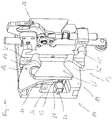
- the illustrated transport device 10 is designed and set up for transporting de-grazed poultry carcasses or parts thereof in the transport direction T along a transport path. Different processing stations that require different positioning of the poultry carcasses or parts thereof can be arranged along the transport path.
- the transport device 10 comprises an endlessly rotating transport unit 11 and at least one transport saddle 12 attached to it for holding and positioning the poultry carcasses or parts thereof during transport, with a holding device 13 being provided for fastening the transport saddle 12 to the transport unit 11, which consists of one of the Transport unit 11 assigned receiving body 14 and the transport saddle 12 associated fastening body 15, which is detachably connected to the receiving body 14 and rotatably mounted about an axis of rotation in the receiving body 14, the holding device 13 comprises a latching device 16, by means of which the fastening body 15 and thus the transport saddle 12 can be locked in at least two different locking positions, the locking device 16 comprising a locking lever 17 and at least two locking bolts 18, the locking lever 17 about a pivot axis S which is oriented parallel to the axis of rotation
- the transport device 10 comprises a first actuating member 20 for actuating the latching lever 17 at least from the locking position into the release position and a second actuating member 21 for rotating the fastening body 15 in the release position of the latching lever 17 .
- this transport device 10 is characterized in that the locking device 16 comprises at least two magnetic elements 22, 23, a first magnetic element 22 being assigned to the receiving body 14 and a second magnetic element 23 being assigned to the locking lever 17 such that each opposite poles of the first magnetic element 22 and of the second magnetic element 23 for pulling the locking lever 17 into the locking position are opposite each other in an attractive manner.
- the circumferentially driven transport unit 11 is guided around deflection and / or drive elements that are not explicitly shown.
- the axes of rotation of the deflection and / or rotating elements can be aligned horizontally, e.g. to form an upper run and a lower run. However, the axes of rotation can also have any other orientation, e.g. 45 ° to the horizontal orientation.
- Several transport saddles are preferably arranged on the transport unit.
- the transport path extends over the entire circumferential length of the transport unit 11.
- the transport unit 11 can be driven intermittently or continuously by means of a drive means.
- the drive means is preferably connected to a control device.
- the holding devices 13 and more precisely the receiving bodies 14 comprise fastening means 52 with which the connection to the transport unit 11 is established.
- Each transport saddle 12 can be formed in one piece or in several pieces.
- the transport saddle 12 comprises the fastening body 15 and a support body 24, which is preferably detachably connected to the fastening body 15.
- the fastening body 15 can also be formed in one piece or in several pieces.
- the fastening body 15 preferably comprises a rotating body 25 made of plastic and a clamping body 26 made of metal, for example stainless steel.
- the latching device 16 preferably comprises a third magnetic element 27, which is assigned to the receiving body 14 and placed on the side of the latching lever 17 opposite the first magnetic element 22, in such a way that poles of the same name of the second magnetic element 23 and the third magnetic element 27 for the Pressing the locking lever 17 into the locking position oppose each other in a repulsive manner.
- the north pole of the first magnetic element 22 and the south pole of the second magnetic element 23 are directly or slightly spaced from one another, while the north pole of the second magnetic element 23 and the north pole of the third magnetic element 27 are directly or slightly spaced from one another.
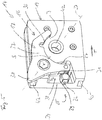
- the base body 19 of the receiving body 14 has a recess 28 at its end E trailing in the transport direction T on the side facing the fastening body 15 (see in particular Figure 5 ), into which the latching lever 17 with a projection 29 dips at least in sections, the first magnetic element 22 being positioned in the recess 28 of the base body 19 in the area of a rear wall 30 and the second magnetic element 23 in the projection 29 of the latching lever 17.
- the locking lever 17 in relation to the base body 19 are also possible.
- the recess 28 can also be formed at the leading end.
- the third magnetic element 27 is positioned in the recess 28 of the base body 19 in the area of a side wall 51 such that the latching lever 17 with its projection 29, in which the second magnetic element 23 is located, is sandwiched between the first and the third magnetic element 22, 27 is arranged.
- the magnetic elements 22, 23, 27 can be placed on the base body 19 or the latching lever 17. At least the third magnetic element is preferably embedded in the base body 19.
- the rear wall 33 of the base body 19 and thus also the rear wall 30 of the recess 28 are completely closed educated.
- the base body 19 has an opening 31 in the region of the recess 28, the main orientation of which is parallel to the pivot axis S and the axis of rotation D, in such a way that the free end of the projection 29 of the locking lever 17 dips into this opening 31 at least in sections , in such a way that a side wall 32 of the opening 31 is designed in addition to the locking bolt 18 as a stop for the locking lever 17 in its locking position.
- the opening 31 is formed at a distance from the trailing end E, so that a connecting web 34 is formed, on which or on which the first magnetic element 22 is arranged.
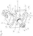
- the mounting body 15 is assigned the rotating body 25 in the form of a Maltese cross, which on the one hand has four recesses 35 offset from one another in the area of the circumference by 90 ° for engaging the actuating member 21 for rotating the mounting body 15, and on the other hand on the side facing the receiving body 14 has at least four locking bolts 18 offset from one another by 90 °, which can be brought into operative connection with the locking lever 17 (see in particular Figure 12 ).
- the preferably square-shaped rotating body 25, which can also be referred to as a turnstile, has a recess 35 distributed uniformly over the circumference in each of the corner regions.
- the central axes M 1 , M 2 , M 3 and M 4 of the recesses 35 are each aligned at an angle ⁇ of approximately 45 ° to the central axis M of the rotating body 25, which is why the rotating body 25 has the shape of the Maltese cross. Other shapes and structural configurations of the rotating body 25 can also be used.
- the rotating body 25 can be designed differently, for example as a rotating plate, and in particular have fewer than four and more than four recesses 35 and fewer than four and more than four locking bolts 18.
- the grid / pattern of the four recesses 35 is arranged offset about the axis of rotation D by 45 ° to the grid / pattern of the four locking bolts.
- the fastening body 15 has a shaft 41 which is designed for mounting in a bearing bush 42 of the base body 19.
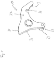
- the preferred embodiment of the locking lever 17 is in particular the Figures 5 , 7th and 8th refer to.
- the locking lever 17 has, on its inner side I facing the axis of rotation D, a recess 36 for receiving a locking bolt 18.
- the Inside I has an arcuate course.
- the arcuate course is interrupted by the recess 36.
- the latching lever 17, which is preferably made in one piece, comprises, in addition to a hook-shaped lever body 37, the projection 29 and an actuating nose 38, which is designed and configured to apply and / or strike the actuating member 20 for pivoting the latching lever 17.
- the second magnetic element 23 is arranged on or in the projection 29.
- the magnetic element 23 itself can be arranged or fastened directly on the lever body 37 and thus form the projection 29.
- the main axis H of the projection 29 runs parallel to the pivot axis S.
- a shaft 39 (see e.g. Figure 7 ) formed or arranged on the locking lever 17, which is designed for storage in a bearing bush 40 of the base body 19.
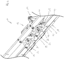
- the transport unit 11 preferably comprises a transport chain 43. At least in sections, at least one guide rail 44 is arranged along the transport chain 43, on which the receiving body 14 of the holding device 13 is guided with a groove 45 formed in the base body 19. Particularly preferably, two guide rails 44, 46 arranged at a distance from one another are arranged at least in sections along the transport chain 43, between which the base body 19 is guided with corresponding grooves 45, 47.
- the actuating member 20 for actuating the latching lever 17 is arranged on one guide rail 46 and the actuating member 21 for rotating the fastening body 15 is arranged on the other guide rail 44.
- the actuating members 20, 21 can also be arranged on a common guide rail 44 or 46.
- the actuating members 20, 21 can also be arranged separately from the guide rails 44, 46.
- the actuating element 21 for rotating the fastening body 15 in the transport direction T of the transport unit is preferably arranged behind the actuating element 20 for actuating the latching lever 17.
- "Behind” does not refer to the structural attachment, but to the position in which the actuating members 20, 21 come into engagement with the latching lever 17 or the fastening body 15.
- the actuating member 20 for pivoting the locking lever 17 can be a simple bolt, Be a stop or the like, which is fixedly arranged on the guide rail 46 and lies in the transport path of the actuating nose 38 of the latching lever 17, such that the latching lever 17 is pivoted out of engagement with the latching bolt 18 by being transported along the transport path when the actuating member 20 is passed.
- the latching lever 17 with the actuating lug 38 protrudes beyond the base body 19 of the receiving body 14 such that the actuating member 20 for actuating the latching lever 17 comes into operative connection with the actuating lug 38 of the latching lever 17 when the transport saddle 12 is passed.
- the actuating member 20 can also be a freely rotatable roller 48 or the like.
- the locking lever 17 should / must be held in the release position over a longer distance, for example in order to rotate the fastening body 15 by a larger angular amount by means of the rotating body 25, the actuating member 20 can, for example, also move in the transport direction T. extending rail or the like.
- the actuating member 20 can also be arranged adjustably on the guide rail 46.
- the actuating member 21 for rotating the fastening body 15 can be a simple angle element 49 or the like, an arm 50 of the angle element 49 protruding into the transport path of the rotating body 25 such that the rotating body 25 engages with a recess 35 when it passes the transport saddle 12 arm 50 comes.
- the further transport in the transport direction T then leads to the rotation of the fastening body 15, in the illustrated embodiment by 90 °.
- Two or more such actuating members 21 can also be arranged one behind the other in the transport direction T in order to come into engagement with the respective next recess 35 of the rotating body 25.
- the magnetic elements 22, 23, 27 are at least partially designed as bar magnets, the bar magnets being aligned with their longitudinal axis in the transport direction T.
- the bar magnets 22, 23, 27 are preferably aligned with their longitudinal axes essentially in alignment with one another.
- at least the first and the third magnetic element 22, 27 are designed as bar magnets.
- the second magnetic element 23 is preferably also designed as a bar magnet.
- the bar magnets are at least partially arranged in blind holes, the open sides of the blind holes optionally being closed by means of a cover in such a way that the bar magnets located within the blind holes are completely shielded from the environment.
- the magnetic elements 22, 23, 27 each comprise permanent magnets and / or electromagnets.
- the permanent magnets are particularly preferably designed as neodymium magnets. Even more preferably, they are nickel-plated neodymium magnets.
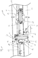
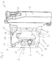
- the functional principle of the locking device 16 is based on the Figure 1 explained in more detail.
- the transport saddles 12 are driven in a rotating manner by means of the transport chain 43.
- the first transport saddle 12 in the transport direction T is oriented vertically with its main axis.
- the locking lever 17 strikes with its actuating nose 38 against the roller 48.
- the locking lever 17 (in the embodiment according to FIG Figure 1 ) pivoted counterclockwise about the pivot axis S and thus pivoted out of engagement with the locking bolt 18 of the fastening body 15 into the release position.
- the fastening body 15 and thus the transport saddle 12 are freely rotatable in this phase.
- the rotating body 25 of the fastening body 15 meets the arm 50 of the angle element 49 with one of the recesses 35 and forms an operative connection, which leads to the freely rotatable rotating body 25 being further Moving in the transport direction T against the standing arm 50 (in the embodiment according to FIG Figure 1 ) is rotated clockwise around the axis of rotation D.
- a locking bolt 18 runs on the inside I of the locking lever 17.
- the locking lever 17 continues to be held in the release position.
- the locking lever 17 snaps back into the locking position due to the attraction of the first and second magnetic elements 22, 23.
- the repulsive effect of the second and third magnetic elements 23, 27 is supported by this movement of the locking lever 17.
- the main axis of the transport saddle 12 is thus aligned horizontally.
Landscapes
- Life Sciences & Earth Sciences (AREA)
- Engineering & Computer Science (AREA)
- Food Science & Technology (AREA)
- Wood Science & Technology (AREA)
- Zoology (AREA)
- Processing Of Meat And Fish (AREA)
- Chain Conveyers (AREA)
Priority Applications (11)
| Application Number | Priority Date | Filing Date | Title |
|---|---|---|---|
| PL19171118T PL3729968T3 (pl) | 2019-04-25 | 2019-04-25 | Urządzenie transportowe do transportu wypatroszonych tuszek drobiowych lub ich części |
| ES19171118T ES2906400T3 (es) | 2019-04-25 | 2019-04-25 | Dispositivo de transporte para transportar canales de ave evisceradas o partes de ellas |
| DK19171118.3T DK3729968T3 (da) | 2019-04-25 | 2019-04-25 | Transportindretning til at transportere rensede fjerkrækroppe eller dele deraf |
| EP19171118.3A EP3729968B1 (de) | 2019-04-25 | 2019-04-25 | Transportvorrichtung zum transportieren von entweideten geflügelkörpern oder teilen davon |
| BR112021020714-7A BR112021020714B1 (pt) | 2019-04-25 | 2020-04-22 | Aparelho de transporte para transportar carcaças de aves evisceradas ou partes das mesmas |
| CN202080029747.3A CN113784621B (zh) | 2019-04-25 | 2020-04-22 | 用于输送去内脏的家禽屠体或其部分的输送设备 |
| CA3134376A CA3134376C (en) | 2019-04-25 | 2020-04-22 | Transport device for transporting eviscerated poultry carcasses or parts thereof |
| JP2021562826A JP7168797B2 (ja) | 2019-04-25 | 2020-04-22 | 内臓摘出された家禽の死骸またはその一部を移送するための移送デバイス |
| PCT/EP2020/061205 WO2020216787A1 (de) | 2019-04-25 | 2020-04-22 | Transportvorrichtung zum transportieren von entweideten geflügelkörpern oder teilen davon |
| US17/605,131 US11484037B2 (en) | 2019-04-25 | 2020-04-22 | Transport device for transporting eviscerated poultry carcasses or parts thereof |
| KR1020217035300A KR102434683B1 (ko) | 2019-04-25 | 2020-04-22 | 내장을 제거한 가금류 사체 또는 그 일부를 이송하기 위한 이송 장치 |
Applications Claiming Priority (1)
| Application Number | Priority Date | Filing Date | Title |
|---|---|---|---|
| EP19171118.3A EP3729968B1 (de) | 2019-04-25 | 2019-04-25 | Transportvorrichtung zum transportieren von entweideten geflügelkörpern oder teilen davon |
Publications (2)
| Publication Number | Publication Date |
|---|---|
| EP3729968A1 EP3729968A1 (de) | 2020-10-28 |
| EP3729968B1 true EP3729968B1 (de) | 2021-12-29 |
Family
ID=66286234
Family Applications (1)
| Application Number | Title | Priority Date | Filing Date |
|---|---|---|---|
| EP19171118.3A Active EP3729968B1 (de) | 2019-04-25 | 2019-04-25 | Transportvorrichtung zum transportieren von entweideten geflügelkörpern oder teilen davon |
Country Status (11)
| Country | Link |
|---|---|
| US (1) | US11484037B2 (pl) |
| EP (1) | EP3729968B1 (pl) |
| JP (1) | JP7168797B2 (pl) |
| KR (1) | KR102434683B1 (pl) |
| CN (1) | CN113784621B (pl) |
| BR (1) | BR112021020714B1 (pl) |
| CA (1) | CA3134376C (pl) |
| DK (1) | DK3729968T3 (pl) |
| ES (1) | ES2906400T3 (pl) |
| PL (1) | PL3729968T3 (pl) |
| WO (1) | WO2020216787A1 (pl) |
Citations (6)
| Publication number | Priority date | Publication date | Assignee | Title |
|---|---|---|---|---|
| EP0935922A1 (en) | 1998-02-17 | 1999-08-18 | Systemate Holland B.V. | Rotary shackle with position lock |
| US8789684B2 (en) | 2010-04-19 | 2014-07-29 | Foodmate Bv | Rotatable article support for a conveyor |
| WO2015065190A1 (en) | 2013-11-01 | 2015-05-07 | Foodmate B.V. | Method and system for automatically deboning poultry breast caps containing meat and a skeletal structure to obtain breast fillets therefrom |
| US9185918B2 (en) | 2011-01-26 | 2015-11-17 | Foodmate Bv | Meat processing equipment having improved yieldable arresting means |
| US9615591B1 (en) | 2015-11-20 | 2017-04-11 | Foodmate B.V. | Meat stripper with articulating stripper plate assembly |
| WO2019001728A1 (de) | 2017-06-30 | 2019-01-03 | Nordischer Maschinenbau Rud. Baader Gmbh + Co. Kg | Fördereinrichtung und verfahren zum fördern von geflügelkörpern sowie vorrichtung und verfahren zur filetgewinnung von geflügelkörpern |
Family Cites Families (18)
| Publication number | Priority date | Publication date | Assignee | Title |
|---|---|---|---|---|
| US4780930A (en) * | 1987-08-31 | 1988-11-01 | Fabricated Products | Poultry cutter with a rotatable arbor and guide means |
| DE58902088D1 (de) * | 1989-01-28 | 1992-09-24 | Nordischer Maschinenbau | Verfahren zum maschinellen gewinnen des fleisches von gefluegelkoerpern und vorrichtung zur durchfuehrung des verfahrens. |
| US5045022A (en) * | 1990-01-31 | 1991-09-03 | Hazenbroek Jacobus E | Adjustable poultry breast filleting system |
| DE4134621C1 (pl) * | 1991-10-19 | 1992-10-29 | Nordischer Maschinenbau Rud. Baader Gmbh + Co Kg, 2400 Luebeck, De | |
| NL1028142C2 (nl) | 2005-01-28 | 2006-07-31 | Stork Pmt | Transportinrichting voor geslacht gevogelte. |
| NL1028561C2 (nl) | 2005-03-17 | 2006-09-20 | Stork Pmt | Bewerken van karkasdelen van geslacht gevogelte. |
| EP2332419A3 (en) * | 2005-12-09 | 2013-05-01 | Marel Stork Poultry Processing B.V. | Method and device for processing a carcass part of slaughtered poultry |
| NL2001993C (en) * | 2008-09-18 | 2010-03-19 | Meyn Food Proc Technology Bv | Method and apparatus for processing poultry or a part thereof. |
| US8757354B2 (en) * | 2010-04-19 | 2014-06-24 | Foodmate Bv | Turning block alignment |
| DE102010047660B4 (de) | 2010-09-30 | 2016-09-01 | Nordischer Maschinenbau Rud. Baader Gmbh + Co. Kg | Vorrichtung und Verfahren zum vollständigen Lösen zumindest eines Teils des Brustknorpels von einer vom Brustfleisch befreiten Geflügelkarkasse |
| EP2606735B1 (de) | 2011-12-23 | 2014-10-29 | Nordischer Maschinenbau Rud. Baader GmbH + Co. KG | Vorrichtung und Verfahren zum vollständigen Trennen bereits teilweise von der Karkasse eines entweideten Geflügelkörpers gelösten Brustfilets von der Karkasse |
| NL2008729C2 (en) | 2012-04-27 | 2013-10-29 | Meyn Food Proc Technology Bv | A method and apparatus for processing a poultry carcass part. |
| US9078453B2 (en) * | 2013-11-01 | 2015-07-14 | Foodmate B.V. | Method and system for automatically deboning poultry breast caps containing meat and a skeletal structure to obtain breast fillets therefrom |
| RU2641731C1 (ru) * | 2014-02-07 | 2018-01-22 | ЛИНКО Фуд Системс А/С | Устройство позиционирования для позиционирования ног домашней птицы, перемещаемых по одной в направлении перемещения вдоль секции перемещения, и способ, включающий позиционирование для удаления мяса с бедренной части ноги домашней птицы |
| NL2012386B1 (nl) * | 2014-03-10 | 2015-11-26 | Marel Stork Poultry Proc Bv | Inrichting en werkwijze voor het wijzigen van de oriëntatie van slachtproducten. |
| NL2015436B1 (en) * | 2015-09-14 | 2017-04-19 | Foodmate Bv | Apparatus, system and method for removing furculae from poultry breast caps. |
| EP3516964B1 (de) * | 2018-01-26 | 2026-02-25 | Nordischer Maschinenbau Rud. Baader Gmbh + Co Kg | Haltevorrichtung zum halten von entweideten geflügelkörpern oder teilen davon während der bearbeitung in einer vorrichtung zur verarbeitung von entweideten geflügelkörpern oder teilen davon |
| NL2020679B1 (en) * | 2018-03-28 | 2019-10-07 | Meyn Food Processing Tech Bv | System for placement of a supply of poultry front halves in an ordered sequence in a processing line |
-
2019
- 2019-04-25 PL PL19171118T patent/PL3729968T3/pl unknown
- 2019-04-25 ES ES19171118T patent/ES2906400T3/es active Active
- 2019-04-25 EP EP19171118.3A patent/EP3729968B1/de active Active
- 2019-04-25 DK DK19171118.3T patent/DK3729968T3/da active
-
2020
- 2020-04-22 CA CA3134376A patent/CA3134376C/en active Active
- 2020-04-22 KR KR1020217035300A patent/KR102434683B1/ko active Active
- 2020-04-22 WO PCT/EP2020/061205 patent/WO2020216787A1/de not_active Ceased
- 2020-04-22 CN CN202080029747.3A patent/CN113784621B/zh active Active
- 2020-04-22 US US17/605,131 patent/US11484037B2/en active Active
- 2020-04-22 JP JP2021562826A patent/JP7168797B2/ja active Active
- 2020-04-22 BR BR112021020714-7A patent/BR112021020714B1/pt active IP Right Grant
Patent Citations (6)
| Publication number | Priority date | Publication date | Assignee | Title |
|---|---|---|---|---|
| EP0935922A1 (en) | 1998-02-17 | 1999-08-18 | Systemate Holland B.V. | Rotary shackle with position lock |
| US8789684B2 (en) | 2010-04-19 | 2014-07-29 | Foodmate Bv | Rotatable article support for a conveyor |
| US9185918B2 (en) | 2011-01-26 | 2015-11-17 | Foodmate Bv | Meat processing equipment having improved yieldable arresting means |
| WO2015065190A1 (en) | 2013-11-01 | 2015-05-07 | Foodmate B.V. | Method and system for automatically deboning poultry breast caps containing meat and a skeletal structure to obtain breast fillets therefrom |
| US9615591B1 (en) | 2015-11-20 | 2017-04-11 | Foodmate B.V. | Meat stripper with articulating stripper plate assembly |
| WO2019001728A1 (de) | 2017-06-30 | 2019-01-03 | Nordischer Maschinenbau Rud. Baader Gmbh + Co. Kg | Fördereinrichtung und verfahren zum fördern von geflügelkörpern sowie vorrichtung und verfahren zur filetgewinnung von geflügelkörpern |
Also Published As
| Publication number | Publication date |
|---|---|
| KR20210136144A (ko) | 2021-11-16 |
| CN113784621B (zh) | 2022-09-06 |
| JP2022525240A (ja) | 2022-05-11 |
| EP3729968A1 (de) | 2020-10-28 |
| WO2020216787A1 (de) | 2020-10-29 |
| US20220142189A1 (en) | 2022-05-12 |
| CA3134376A1 (en) | 2020-10-29 |
| CA3134376C (en) | 2022-05-17 |
| ES2906400T3 (es) | 2022-04-18 |
| JP7168797B2 (ja) | 2022-11-09 |
| KR102434683B1 (ko) | 2022-08-19 |
| PL3729968T3 (pl) | 2022-04-11 |
| BR112021020714A2 (pt) | 2022-01-04 |
| DK3729968T3 (da) | 2022-03-28 |
| US11484037B2 (en) | 2022-11-01 |
| CN113784621A (zh) | 2021-12-10 |
| BR112021020714B1 (pt) | 2022-08-23 |
Similar Documents
| Publication | Publication Date | Title |
|---|---|---|
| EP3286118B1 (de) | Behältergreifer sowie transportvorrichtung zum transportieren von behältern | |
| EP2858793B1 (de) | Greiferanordnung | |
| AT510224A1 (de) | Transfer-fördervorrichtung | |
| DE102014111564B4 (de) | Greifarm für Behälter, Steuernocken, Lagereinheit und Greifeinrichtung | |
| EP2546546B1 (de) | Vorrichtung zur Führung von Versorgungsleitungen | |
| EP2621838A1 (de) | Rollenförderer mit einer drehmomentenstütze | |
| DE68902278T2 (de) | Befestigung eines buendels von laenglichen gegenstaenden oder eines nichtkreisfoermigen laenglichen gegenstandes auf einer unterlage. | |
| EP0461372B1 (de) | Vorrichtung zum Verdrehen von Werkstücken, insbesondere zum Wenden von Hülsen | |
| EP3433191A1 (de) | Tragevorrichtung und nockensteuerwelle für greifeinrichtungen | |
| DE202007000112U1 (de) | Verriegelungsanordnung mit einem schwenkbaren Verriegelungshaken und einer verschiebbaren Haltestange | |
| EP3729968B1 (de) | Transportvorrichtung zum transportieren von entweideten geflügelkörpern oder teilen davon | |
| DE4413475A1 (de) | Vorrichtung zum Trennen von auf Rollenbahnen beförderten Paletten | |
| DE4111475C2 (de) | Rohrpostbüchse | |
| DE202023100463U1 (de) | Eingreifschutzvorrichtung für einen Rollenförderer und Rollenförderer | |
| WO1998036385A1 (de) | Transporteinrichtung für einzelblätter | |
| EP2031156A2 (de) | Rückstellmechanismus für einen Türdrücker | |
| DE102017108928B4 (de) | Behältergreifer | |
| EP3693618B1 (de) | Aufbau für mehrfachen schnellverschluss und mehrfache schnellöffnung | |
| DE202011106399U1 (de) | Adapter | |
| DE102010019578A1 (de) | Türöffner | |
| EP3757325B1 (de) | Schiebetürsystem | |
| DE102025100259A1 (de) | Türantrieb für einen Türflügel mit Rollenkette und Verriegelungseinheit | |
| DE102007046360B4 (de) | Montageeinheit mit integrierter Horizontalfördereinrichtung für Kleinteile | |
| EP3024356B1 (de) | Arretiersystem | |
| DE102010018177A1 (de) | Türöffner |
Legal Events
| Date | Code | Title | Description |
|---|---|---|---|
| PUAI | Public reference made under article 153(3) epc to a published international application that has entered the european phase |
Free format text: ORIGINAL CODE: 0009012 |
|
| STAA | Information on the status of an ep patent application or granted ep patent |
Free format text: STATUS: THE APPLICATION HAS BEEN PUBLISHED |
|
| AK | Designated contracting states |
Kind code of ref document: A1 Designated state(s): AL AT BE BG CH CY CZ DE DK EE ES FI FR GB GR HR HU IE IS IT LI LT LU LV MC MK MT NL NO PL PT RO RS SE SI SK SM TR |
|
| AX | Request for extension of the european patent |
Extension state: BA ME |
|
| STAA | Information on the status of an ep patent application or granted ep patent |
Free format text: STATUS: REQUEST FOR EXAMINATION WAS MADE |
|
| 17P | Request for examination filed |
Effective date: 20210406 |
|
| RBV | Designated contracting states (corrected) |
Designated state(s): AL AT BE BG CH CY CZ DE DK EE ES FI FR GB GR HR HU IE IS IT LI LT LU LV MC MK MT NL NO PL PT RO RS SE SI SK SM TR |
|
| GRAP | Despatch of communication of intention to grant a patent |
Free format text: ORIGINAL CODE: EPIDOSNIGR1 |
|
| STAA | Information on the status of an ep patent application or granted ep patent |
Free format text: STATUS: GRANT OF PATENT IS INTENDED |
|
| INTG | Intention to grant announced |
Effective date: 20210922 |
|
| GRAS | Grant fee paid |
Free format text: ORIGINAL CODE: EPIDOSNIGR3 |
|
| GRAA | (expected) grant |
Free format text: ORIGINAL CODE: 0009210 |
|
| STAA | Information on the status of an ep patent application or granted ep patent |
Free format text: STATUS: THE PATENT HAS BEEN GRANTED |
|
| AK | Designated contracting states |
Kind code of ref document: B1 Designated state(s): AL AT BE BG CH CY CZ DE DK EE ES FI FR GB GR HR HU IE IS IT LI LT LU LV MC MK MT NL NO PL PT RO RS SE SI SK SM TR |
|
| REG | Reference to a national code |
Ref country code: GB Ref legal event code: FG4D Free format text: NOT ENGLISH |
|
| REG | Reference to a national code |
Ref country code: CH Ref legal event code: EP |
|
| REG | Reference to a national code |
Ref country code: AT Ref legal event code: REF Ref document number: 1458007 Country of ref document: AT Kind code of ref document: T Effective date: 20220115 |
|
| REG | Reference to a national code |
Ref country code: IE Ref legal event code: FG4D Free format text: LANGUAGE OF EP DOCUMENT: GERMAN |
|
| REG | Reference to a national code |
Ref country code: DE Ref legal event code: R096 Ref document number: 502019003084 Country of ref document: DE |
|
| REG | Reference to a national code |
Ref country code: DK Ref legal event code: T3 Effective date: 20220322 |
|
| REG | Reference to a national code |
Ref country code: SE Ref legal event code: TRGR |
|
| REG | Reference to a national code |
Ref country code: NL Ref legal event code: FP |
|
| REG | Reference to a national code |
Ref country code: LT Ref legal event code: MG9D |
|
| REG | Reference to a national code |
Ref country code: ES Ref legal event code: FG2A Ref document number: 2906400 Country of ref document: ES Kind code of ref document: T3 Effective date: 20220418 |
|
| PG25 | Lapsed in a contracting state [announced via postgrant information from national office to epo] |
Ref country code: RS Free format text: LAPSE BECAUSE OF FAILURE TO SUBMIT A TRANSLATION OF THE DESCRIPTION OR TO PAY THE FEE WITHIN THE PRESCRIBED TIME-LIMIT Effective date: 20211229 Ref country code: LT Free format text: LAPSE BECAUSE OF FAILURE TO SUBMIT A TRANSLATION OF THE DESCRIPTION OR TO PAY THE FEE WITHIN THE PRESCRIBED TIME-LIMIT Effective date: 20211229 Ref country code: FI Free format text: LAPSE BECAUSE OF FAILURE TO SUBMIT A TRANSLATION OF THE DESCRIPTION OR TO PAY THE FEE WITHIN THE PRESCRIBED TIME-LIMIT Effective date: 20211229 Ref country code: BG Free format text: LAPSE BECAUSE OF FAILURE TO SUBMIT A TRANSLATION OF THE DESCRIPTION OR TO PAY THE FEE WITHIN THE PRESCRIBED TIME-LIMIT Effective date: 20220329 |
|
| PG25 | Lapsed in a contracting state [announced via postgrant information from national office to epo] |
Ref country code: NO Free format text: LAPSE BECAUSE OF FAILURE TO SUBMIT A TRANSLATION OF THE DESCRIPTION OR TO PAY THE FEE WITHIN THE PRESCRIBED TIME-LIMIT Effective date: 20220329 Ref country code: LV Free format text: LAPSE BECAUSE OF FAILURE TO SUBMIT A TRANSLATION OF THE DESCRIPTION OR TO PAY THE FEE WITHIN THE PRESCRIBED TIME-LIMIT Effective date: 20211229 Ref country code: HR Free format text: LAPSE BECAUSE OF FAILURE TO SUBMIT A TRANSLATION OF THE DESCRIPTION OR TO PAY THE FEE WITHIN THE PRESCRIBED TIME-LIMIT Effective date: 20211229 Ref country code: GR Free format text: LAPSE BECAUSE OF FAILURE TO SUBMIT A TRANSLATION OF THE DESCRIPTION OR TO PAY THE FEE WITHIN THE PRESCRIBED TIME-LIMIT Effective date: 20220330 |
|
| PG25 | Lapsed in a contracting state [announced via postgrant information from national office to epo] |
Ref country code: SM Free format text: LAPSE BECAUSE OF FAILURE TO SUBMIT A TRANSLATION OF THE DESCRIPTION OR TO PAY THE FEE WITHIN THE PRESCRIBED TIME-LIMIT Effective date: 20211229 Ref country code: SK Free format text: LAPSE BECAUSE OF FAILURE TO SUBMIT A TRANSLATION OF THE DESCRIPTION OR TO PAY THE FEE WITHIN THE PRESCRIBED TIME-LIMIT Effective date: 20211229 Ref country code: RO Free format text: LAPSE BECAUSE OF FAILURE TO SUBMIT A TRANSLATION OF THE DESCRIPTION OR TO PAY THE FEE WITHIN THE PRESCRIBED TIME-LIMIT Effective date: 20211229 Ref country code: PT Free format text: LAPSE BECAUSE OF FAILURE TO SUBMIT A TRANSLATION OF THE DESCRIPTION OR TO PAY THE FEE WITHIN THE PRESCRIBED TIME-LIMIT Effective date: 20220429 Ref country code: EE Free format text: LAPSE BECAUSE OF FAILURE TO SUBMIT A TRANSLATION OF THE DESCRIPTION OR TO PAY THE FEE WITHIN THE PRESCRIBED TIME-LIMIT Effective date: 20211229 Ref country code: CZ Free format text: LAPSE BECAUSE OF FAILURE TO SUBMIT A TRANSLATION OF THE DESCRIPTION OR TO PAY THE FEE WITHIN THE PRESCRIBED TIME-LIMIT Effective date: 20211229 |
|
| REG | Reference to a national code |
Ref country code: DE Ref legal event code: R026 Ref document number: 502019003084 Country of ref document: DE |
|
| PG25 | Lapsed in a contracting state [announced via postgrant information from national office to epo] |
Ref country code: IS Free format text: LAPSE BECAUSE OF FAILURE TO SUBMIT A TRANSLATION OF THE DESCRIPTION OR TO PAY THE FEE WITHIN THE PRESCRIBED TIME-LIMIT Effective date: 20220429 |
|
| PLBI | Opposition filed |
Free format text: ORIGINAL CODE: 0009260 |
|
| PLAX | Notice of opposition and request to file observation + time limit sent |
Free format text: ORIGINAL CODE: EPIDOSNOBS2 |
|
| PG25 | Lapsed in a contracting state [announced via postgrant information from national office to epo] |
Ref country code: AL Free format text: LAPSE BECAUSE OF FAILURE TO SUBMIT A TRANSLATION OF THE DESCRIPTION OR TO PAY THE FEE WITHIN THE PRESCRIBED TIME-LIMIT Effective date: 20211229 |
|
| 26 | Opposition filed |
Opponent name: MAREL POULTRY B.V. Effective date: 20220928 |
|
| REG | Reference to a national code |
Ref country code: CH Ref legal event code: PL |
|
| REG | Reference to a national code |
Ref country code: BE Ref legal event code: MM Effective date: 20220430 |
|
| PG25 | Lapsed in a contracting state [announced via postgrant information from national office to epo] |
Ref country code: MC Free format text: LAPSE BECAUSE OF FAILURE TO SUBMIT A TRANSLATION OF THE DESCRIPTION OR TO PAY THE FEE WITHIN THE PRESCRIBED TIME-LIMIT Effective date: 20211229 Ref country code: LU Free format text: LAPSE BECAUSE OF NON-PAYMENT OF DUE FEES Effective date: 20220425 Ref country code: LI Free format text: LAPSE BECAUSE OF NON-PAYMENT OF DUE FEES Effective date: 20220430 Ref country code: CH Free format text: LAPSE BECAUSE OF NON-PAYMENT OF DUE FEES Effective date: 20220430 |
|
| PLAK | Information related to reply of patent proprietor to notice(s) of opposition modified |
Free format text: ORIGINAL CODE: EPIDOSCOBS3 |
|
| PLBB | Reply of patent proprietor to notice(s) of opposition received |
Free format text: ORIGINAL CODE: EPIDOSNOBS3 |
|
| PG25 | Lapsed in a contracting state [announced via postgrant information from national office to epo] |
Ref country code: SI Free format text: LAPSE BECAUSE OF FAILURE TO SUBMIT A TRANSLATION OF THE DESCRIPTION OR TO PAY THE FEE WITHIN THE PRESCRIBED TIME-LIMIT Effective date: 20211229 Ref country code: BE Free format text: LAPSE BECAUSE OF NON-PAYMENT OF DUE FEES Effective date: 20220430 |
|
| PG25 | Lapsed in a contracting state [announced via postgrant information from national office to epo] |
Ref country code: IE Free format text: LAPSE BECAUSE OF NON-PAYMENT OF DUE FEES Effective date: 20220425 |
|
| PG25 | Lapsed in a contracting state [announced via postgrant information from national office to epo] |
Ref country code: IT Free format text: LAPSE BECAUSE OF FAILURE TO SUBMIT A TRANSLATION OF THE DESCRIPTION OR TO PAY THE FEE WITHIN THE PRESCRIBED TIME-LIMIT Effective date: 20211229 |
|
| P01 | Opt-out of the competence of the unified patent court (upc) registered |
Effective date: 20230517 |
|
| PG25 | Lapsed in a contracting state [announced via postgrant information from national office to epo] |
Ref country code: MK Free format text: LAPSE BECAUSE OF FAILURE TO SUBMIT A TRANSLATION OF THE DESCRIPTION OR TO PAY THE FEE WITHIN THE PRESCRIBED TIME-LIMIT Effective date: 20211229 Ref country code: CY Free format text: LAPSE BECAUSE OF FAILURE TO SUBMIT A TRANSLATION OF THE DESCRIPTION OR TO PAY THE FEE WITHIN THE PRESCRIBED TIME-LIMIT Effective date: 20211229 |
|
| PG25 | Lapsed in a contracting state [announced via postgrant information from national office to epo] |
Ref country code: HU Free format text: LAPSE BECAUSE OF FAILURE TO SUBMIT A TRANSLATION OF THE DESCRIPTION OR TO PAY THE FEE WITHIN THE PRESCRIBED TIME-LIMIT; INVALID AB INITIO Effective date: 20190425 |
|
| PG25 | Lapsed in a contracting state [announced via postgrant information from national office to epo] |
Ref country code: TR Free format text: LAPSE BECAUSE OF FAILURE TO SUBMIT A TRANSLATION OF THE DESCRIPTION OR TO PAY THE FEE WITHIN THE PRESCRIBED TIME-LIMIT Effective date: 20211229 |
|
| PG25 | Lapsed in a contracting state [announced via postgrant information from national office to epo] |
Ref country code: MT Free format text: LAPSE BECAUSE OF FAILURE TO SUBMIT A TRANSLATION OF THE DESCRIPTION OR TO PAY THE FEE WITHIN THE PRESCRIBED TIME-LIMIT Effective date: 20211229 |
|
| PLCK | Communication despatched that opposition was rejected |
Free format text: ORIGINAL CODE: EPIDOSNREJ1 |
|
| REG | Reference to a national code |
Ref country code: DE Ref legal event code: R100 Ref document number: 502019003084 Country of ref document: DE |
|
| PGFP | Annual fee paid to national office [announced via postgrant information from national office to epo] |
Ref country code: PL Payment date: 20250304 Year of fee payment: 7 |
|
| PGFP | Annual fee paid to national office [announced via postgrant information from national office to epo] |
Ref country code: NL Payment date: 20250422 Year of fee payment: 7 |
|
| PLBN | Opposition rejected |
Free format text: ORIGINAL CODE: 0009273 |
|
| STAA | Information on the status of an ep patent application or granted ep patent |
Free format text: STATUS: OPPOSITION REJECTED |
|
| REG | Reference to a national code |
Ref country code: AT Ref legal event code: MM01 Ref document number: 1458007 Country of ref document: AT Kind code of ref document: T Effective date: 20240425 |
|
| 27O | Opposition rejected |
Effective date: 20250218 |
|
| PGFP | Annual fee paid to national office [announced via postgrant information from national office to epo] |
Ref country code: DE Payment date: 20250417 Year of fee payment: 7 |
|
| PGFP | Annual fee paid to national office [announced via postgrant information from national office to epo] |
Ref country code: ES Payment date: 20250519 Year of fee payment: 7 Ref country code: GB Payment date: 20250423 Year of fee payment: 7 Ref country code: DK Payment date: 20250423 Year of fee payment: 7 |
|
| PGFP | Annual fee paid to national office [announced via postgrant information from national office to epo] |
Ref country code: FR Payment date: 20250422 Year of fee payment: 7 |
|
| PG25 | Lapsed in a contracting state [announced via postgrant information from national office to epo] |
Ref country code: AT Free format text: LAPSE BECAUSE OF NON-PAYMENT OF DUE FEES Effective date: 20240425 |
|
| PGFP | Annual fee paid to national office [announced via postgrant information from national office to epo] |
Ref country code: SE Payment date: 20250423 Year of fee payment: 7 |