EP3729968B1 - Transport apparatus for transporting eviscerated poultry bodies or parts thereof - Google Patents
Transport apparatus for transporting eviscerated poultry bodies or parts thereof Download PDFInfo
- Publication number
- EP3729968B1 EP3729968B1 EP19171118.3A EP19171118A EP3729968B1 EP 3729968 B1 EP3729968 B1 EP 3729968B1 EP 19171118 A EP19171118 A EP 19171118A EP 3729968 B1 EP3729968 B1 EP 3729968B1
- Authority
- EP
- European Patent Office
- Prior art keywords
- transport
- latching
- latching lever
- magnetic element
- lever
- Prior art date
- Legal status (The legal status is an assumption and is not a legal conclusion. Google has not performed a legal analysis and makes no representation as to the accuracy of the status listed.)
- Active
Links
Images


Classifications
-
- A—HUMAN NECESSITIES
- A22—BUTCHERING; MEAT TREATMENT; PROCESSING POULTRY OR FISH
- A22C—PROCESSING MEAT, POULTRY, OR FISH
- A22C21/00—Processing poultry
- A22C21/0053—Transferring or conveying devices for poultry
-
- A—HUMAN NECESSITIES
- A22—BUTCHERING; MEAT TREATMENT; PROCESSING POULTRY OR FISH
- A22B—SLAUGHTERING
- A22B7/00—Slaughterhouse arrangements
- A22B7/001—Conveying arrangements
-
- A—HUMAN NECESSITIES
- A22—BUTCHERING; MEAT TREATMENT; PROCESSING POULTRY OR FISH
- A22B—SLAUGHTERING
- A22B7/00—Slaughterhouse arrangements
- A22B7/001—Conveying arrangements
- A22B7/003—Positioning, orienting or supporting carcasses as they are being conveyed
-
- A—HUMAN NECESSITIES
- A22—BUTCHERING; MEAT TREATMENT; PROCESSING POULTRY OR FISH
- A22C—PROCESSING MEAT, POULTRY, OR FISH
- A22C21/00—Processing poultry
- A22C21/0007—Poultry shackles
-
- A—HUMAN NECESSITIES
- A22—BUTCHERING; MEAT TREATMENT; PROCESSING POULTRY OR FISH
- A22C—PROCESSING MEAT, POULTRY, OR FISH
- A22C21/00—Processing poultry
- A22C21/0046—Support devices
Definitions
- the invention relates to a transport device, designed and set up for transporting divested poultry carcasses or parts thereof in the transport direction T along a transport path along which different processing stations can be arranged, comprising an endlessly rotating transport unit and at least one transport saddle attached to it for holding and positioning the poultry carcasses or parts thereof during transport, with a holding device being provided for fastening the transport saddle to the transport unit, which consists of a receiving body assigned to the transport unit and a fastening body assigned to the transport saddle, which is detachably connected to the receiving body and rotatably mounted in the receiving body about an axis of rotation D.
- the holding device comprises a latching device, by means of which the fastening body and thus the transport saddle in at least two different latching positions ions can be locked
- the locking device comprising a locking lever and at least two locking bolts, the locking lever being arranged on a base body of the receiving body so as to be pivotable about a pivot axis S, which is aligned parallel to the axis of rotation D, and from a locking position in which the locking lever is connected to a Locking bolt, which is assigned to the fastening body, is engaged in a release position in which the locking lever is out of engagement with a locking bolt of the fastening body, and can be moved back
- the transport device having a first actuating member for actuating the locking lever at least from the locking position into the Release position and a second actuating member for rotating the fastening body in the release position of the locking lever.
- Such transport devices are used in the food processing industry to carry products to be processed along the transport path to bring different processing stations into engagement (cf. WO 2015/065190 A1 ). During processing, the products must be fixed in a defined position.
- every transport saddle is therefore in its locked position.
- This means that the locking lever is in engagement with the fastening body and thereby prevents the transport saddle from rotating.
- the products located on the transport saddle have to be positioned for different processing steps, however, in some cases in different orientations in relation to the processing stations.
- the lock In order to move the transport saddle and thus the saddled-on products or parts thereof into a different position, on the one hand the lock has to be released and on the other hand the transport saddle has to be rotated.
- the actuators are arranged accordingly. By contact of the actuating member for actuating the locking lever with the same, this is pivoted about the pivot axis S out of engagement with the locking bolt located on the fastening body into the release position.
- This release position is held until the downstream actuating member for rotating the fastening body is in engagement or in operative connection with it.
- the fastening body is rotated until the latching lever engages with the next following latching bolt of the fastening body.
- the locking lever of the locking device is spring-actuated.
- a spring is arranged on the receiving body which basically holds the latching lever in the locking position, the spring being essentially relaxed in the locking position. This means that only a small force acts in the locking position.
- the spring pulls the latching lever quasi into the locking position in which the latching lever is in a latching position with a latching bolt of the fastening body.
- the highest spring force of the spring of the latching device acts in the release position, while the lowest spring force acts in the locking position.
- the latching lever is only held in the locking position with a small force.
- the repeated movement of the detent lever from the detent position into the release position has a wear-promoting effect due to the force resistances that act and, above all, increase, so that the service life of the springs is limited.
- a spring solution or the associated spring requires more installation space and is difficult to clean due to the uneven surface structure.
- the invention is therefore based on the object of proposing a transport device with a compact and easy-to-clean latching device that ensures safe and low-wear positioning of the transport saddles and locking them in the locking position.
- a transport device characterized in that the locking device comprises at least two magnetic elements, a first magnetic element being assigned to the receiving body and a second magnetic element being assigned to the locking lever, such that unlike poles of the first magnetic Element and the second magnetic element for pulling the detent lever into the locking position oppose each other attractively. Because the spring solution is replaced by a magnet solution, a long-lasting and easy-to-clean latching device for the transport device is created in a simple manner.
- the technical effect that the greatest (holding) force of the latching device exists in the locking position is particularly advantageous, which leads to a particularly safe and precise positioning of the transport saddles, and a lower and, above all, decreasing one Force in the release position, which means that there is less mechanical stress on the locking device.
- the locking device comprises a third magnetic element which is assigned to the receiving body and is placed on the side of the locking lever opposite the first magnetic element, in such a way that poles of the same name of the second magnetic element and the third magnetic element face each other in a repulsive manner to press the locking lever into the locking position.
- the first and second magnetic elements ensure that the locking lever is securely held in the locking position.
- the third magnetic element ensures that the locking lever is pressed reliably and quickly from the release position back into the locking position. This optimizes the reliable functionality of the latching device.
- the base body of the receiving body has, at its end trailing in the transport direction T, on the side facing the fastening body, a recess into which the latching lever with a projection dips at least in sections, the first magnetic element in the recess of the base body in the area of a Rear wall and the second magnetic element is positioned in the projection of the locking lever.
- the third magnetic element is advantageously positioned in the recess of the base body in the area of a side wall such that the latching lever with its projection, in which the second magnetic element is located, is sandwiched between the first and the third magnetic element.
- the serial arrangement of the magnetic elements ensures, on the one hand, that the latching lever is pulled for secure locking and, on the other hand, that the latching lever is reliably pushed out of the release position back into the locking position. Furthermore, this arrangement enables a space-saving and thus space-reducing design of the latching device.
- the base body has an opening in the area of the recess, the main orientation of which is parallel to the pivot axis S and the axis of rotation D, in such a way that the free end of the projection of the locking lever dips into this opening at least in sections, in such a way that that a side wall of the opening is designed in addition to the locking bolt as a stop for the locking lever in its locking position.
- the base body has a circumferential opening delimited by side walls transversely to the transport direction T, one side wall, namely the side wall trailing in the transport direction T, forming a stop or contact surface for the projection of the locking lever. This increases the stability of the locking device.
- the fastening body is assigned a rotating body in the form of a Maltese cross, which on the one hand has four recesses arranged offset from one another in the area of the circumference by 90 ° for engaging the actuating member to rotate the fastening body and, on the other hand, at least four by 90 ° on the side facing the receiving body has latching bolts which are offset from one another and which can be brought into operative connection with the latching lever.
- the locking lever advantageously has a recess for receiving a locking bolt on its inside facing the axis of rotation D.
- the inside has an arcuate course overall, the arcuate course being interrupted by the recess.
- the size of the recess is adapted to the locking pin.
- the locking bolt lies in the recess so that the fastening body is prevented from rotating.
- the fastening body can be rotated, with a subsequent latching bolt sliding on the arcuate inside of the latching lever during rotation until the latching bolt "snaps" into the recess again. This ensures a particularly simple and yet particularly secure twisting and locking.
- the transport unit preferably comprises a transport chain and there is at least one guide rail at least in sections along the transport chain arranged on which the receiving body of the holding device is guided with a groove formed in the base body. This ensures that the transport chain runs smoothly and that the transport saddles are precisely positioned.
- two spaced apart guide rails are arranged at least in sections along the transport chain, between which the base body is guided with corresponding grooves, the actuating member for actuating the latching lever being arranged on one guide rail and the actuating member for rotating the fastening body on the other guide rail is.
- the actuating element for rotating the fastening body in the transport direction T of the transport unit is expediently arranged behind the actuating element for actuating the latching lever. This ensures a particularly simple structure of the transport device.
- An advantageous embodiment is characterized in that the latching lever protrudes with an actuating lug over the base body of the receiving body, such that the actuating element for actuating the latching lever comes into operative connection with the actuating lug of the latching lever when passing the transport saddle.
- the magnetic elements are advantageously designed at least partially as bar magnets, the bar magnets being aligned with their longitudinal axis in the transport direction T. In this way, a space-saving arrangement of the magnetic elements is ensured, in which poles of different names face one another between the first and the second magnetic element, while poles of the same name face one another between the second and the third magnetic element.
- the bar magnets are at least partially arranged in blind holes, the open sides of the blind holes being closed by means of a cover in such a way that those located inside the blind holes Bar magnets are completely shielded from the environment. Because the bar magnets are arranged in closed pockets, the bar magnets are protected against contamination and smooth surfaces are created that are particularly easy to clean.
- the transport device shown only in part in the drawing, is used to transport and position de-grazed poultry carcasses or parts thereof, such as breast caps or front halves.
- the transport device can also be used in a corresponding manner for other products which should be able to be positioned in different positions along the transport path.
- the illustrated transport device 10 is designed and set up for transporting de-grazed poultry carcasses or parts thereof in the transport direction T along a transport path. Different processing stations that require different positioning of the poultry carcasses or parts thereof can be arranged along the transport path.
- the transport device 10 comprises an endlessly rotating transport unit 11 and at least one transport saddle 12 attached to it for holding and positioning the poultry carcasses or parts thereof during transport, with a holding device 13 being provided for fastening the transport saddle 12 to the transport unit 11, which consists of one of the Transport unit 11 assigned receiving body 14 and the transport saddle 12 associated fastening body 15, which is detachably connected to the receiving body 14 and rotatably mounted about an axis of rotation in the receiving body 14, the holding device 13 comprises a latching device 16, by means of which the fastening body 15 and thus the transport saddle 12 can be locked in at least two different locking positions, the locking device 16 comprising a locking lever 17 and at least two locking bolts 18, the locking lever 17 about a pivot axis S which is oriented parallel to the axis of rotation
- the transport device 10 comprises a first actuating member 20 for actuating the latching lever 17 at least from the locking position into the release position and a second actuating member 21 for rotating the fastening body 15 in the release position of the latching lever 17 .
- this transport device 10 is characterized in that the locking device 16 comprises at least two magnetic elements 22, 23, a first magnetic element 22 being assigned to the receiving body 14 and a second magnetic element 23 being assigned to the locking lever 17 such that each opposite poles of the first magnetic element 22 and of the second magnetic element 23 for pulling the locking lever 17 into the locking position are opposite each other in an attractive manner.
- the circumferentially driven transport unit 11 is guided around deflection and / or drive elements that are not explicitly shown.
- the axes of rotation of the deflection and / or rotating elements can be aligned horizontally, e.g. to form an upper run and a lower run. However, the axes of rotation can also have any other orientation, e.g. 45 ° to the horizontal orientation.
- Several transport saddles are preferably arranged on the transport unit.
- the transport path extends over the entire circumferential length of the transport unit 11.
- the transport unit 11 can be driven intermittently or continuously by means of a drive means.
- the drive means is preferably connected to a control device.
- the holding devices 13 and more precisely the receiving bodies 14 comprise fastening means 52 with which the connection to the transport unit 11 is established.
- Each transport saddle 12 can be formed in one piece or in several pieces.
- the transport saddle 12 comprises the fastening body 15 and a support body 24, which is preferably detachably connected to the fastening body 15.
- the fastening body 15 can also be formed in one piece or in several pieces.
- the fastening body 15 preferably comprises a rotating body 25 made of plastic and a clamping body 26 made of metal, for example stainless steel.
- the latching device 16 preferably comprises a third magnetic element 27, which is assigned to the receiving body 14 and placed on the side of the latching lever 17 opposite the first magnetic element 22, in such a way that poles of the same name of the second magnetic element 23 and the third magnetic element 27 for the Pressing the locking lever 17 into the locking position oppose each other in a repulsive manner.
- the north pole of the first magnetic element 22 and the south pole of the second magnetic element 23 are directly or slightly spaced from one another, while the north pole of the second magnetic element 23 and the north pole of the third magnetic element 27 are directly or slightly spaced from one another.
- the base body 19 of the receiving body 14 has a recess 28 at its end E trailing in the transport direction T on the side facing the fastening body 15 (see in particular Figure 5 ), into which the latching lever 17 with a projection 29 dips at least in sections, the first magnetic element 22 being positioned in the recess 28 of the base body 19 in the area of a rear wall 30 and the second magnetic element 23 in the projection 29 of the latching lever 17.
- the locking lever 17 in relation to the base body 19 are also possible.
- the recess 28 can also be formed at the leading end.
- the third magnetic element 27 is positioned in the recess 28 of the base body 19 in the area of a side wall 51 such that the latching lever 17 with its projection 29, in which the second magnetic element 23 is located, is sandwiched between the first and the third magnetic element 22, 27 is arranged.
- the magnetic elements 22, 23, 27 can be placed on the base body 19 or the latching lever 17. At least the third magnetic element is preferably embedded in the base body 19.
- the rear wall 33 of the base body 19 and thus also the rear wall 30 of the recess 28 are completely closed educated.
- the base body 19 has an opening 31 in the region of the recess 28, the main orientation of which is parallel to the pivot axis S and the axis of rotation D, in such a way that the free end of the projection 29 of the locking lever 17 dips into this opening 31 at least in sections , in such a way that a side wall 32 of the opening 31 is designed in addition to the locking bolt 18 as a stop for the locking lever 17 in its locking position.
- the opening 31 is formed at a distance from the trailing end E, so that a connecting web 34 is formed, on which or on which the first magnetic element 22 is arranged.
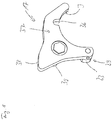
- the mounting body 15 is assigned the rotating body 25 in the form of a Maltese cross, which on the one hand has four recesses 35 offset from one another in the area of the circumference by 90 ° for engaging the actuating member 21 for rotating the mounting body 15, and on the other hand on the side facing the receiving body 14 has at least four locking bolts 18 offset from one another by 90 °, which can be brought into operative connection with the locking lever 17 (see in particular Figure 12 ).
- the preferably square-shaped rotating body 25, which can also be referred to as a turnstile, has a recess 35 distributed uniformly over the circumference in each of the corner regions.
- the central axes M 1 , M 2 , M 3 and M 4 of the recesses 35 are each aligned at an angle ⁇ of approximately 45 ° to the central axis M of the rotating body 25, which is why the rotating body 25 has the shape of the Maltese cross. Other shapes and structural configurations of the rotating body 25 can also be used.
- the rotating body 25 can be designed differently, for example as a rotating plate, and in particular have fewer than four and more than four recesses 35 and fewer than four and more than four locking bolts 18.
- the grid / pattern of the four recesses 35 is arranged offset about the axis of rotation D by 45 ° to the grid / pattern of the four locking bolts.
- the fastening body 15 has a shaft 41 which is designed for mounting in a bearing bush 42 of the base body 19.
- the preferred embodiment of the locking lever 17 is in particular the Figures 5 , 7th and 8th refer to.
- the locking lever 17 has, on its inner side I facing the axis of rotation D, a recess 36 for receiving a locking bolt 18.
- the Inside I has an arcuate course.
- the arcuate course is interrupted by the recess 36.
- the latching lever 17, which is preferably made in one piece, comprises, in addition to a hook-shaped lever body 37, the projection 29 and an actuating nose 38, which is designed and configured to apply and / or strike the actuating member 20 for pivoting the latching lever 17.
- the second magnetic element 23 is arranged on or in the projection 29.
- the magnetic element 23 itself can be arranged or fastened directly on the lever body 37 and thus form the projection 29.
- the main axis H of the projection 29 runs parallel to the pivot axis S.
- a shaft 39 (see e.g. Figure 7 ) formed or arranged on the locking lever 17, which is designed for storage in a bearing bush 40 of the base body 19.
- the transport unit 11 preferably comprises a transport chain 43. At least in sections, at least one guide rail 44 is arranged along the transport chain 43, on which the receiving body 14 of the holding device 13 is guided with a groove 45 formed in the base body 19. Particularly preferably, two guide rails 44, 46 arranged at a distance from one another are arranged at least in sections along the transport chain 43, between which the base body 19 is guided with corresponding grooves 45, 47.
- the actuating member 20 for actuating the latching lever 17 is arranged on one guide rail 46 and the actuating member 21 for rotating the fastening body 15 is arranged on the other guide rail 44.
- the actuating members 20, 21 can also be arranged on a common guide rail 44 or 46.
- the actuating members 20, 21 can also be arranged separately from the guide rails 44, 46.
- the actuating element 21 for rotating the fastening body 15 in the transport direction T of the transport unit is preferably arranged behind the actuating element 20 for actuating the latching lever 17.
- "Behind” does not refer to the structural attachment, but to the position in which the actuating members 20, 21 come into engagement with the latching lever 17 or the fastening body 15.
- the actuating member 20 for pivoting the locking lever 17 can be a simple bolt, Be a stop or the like, which is fixedly arranged on the guide rail 46 and lies in the transport path of the actuating nose 38 of the latching lever 17, such that the latching lever 17 is pivoted out of engagement with the latching bolt 18 by being transported along the transport path when the actuating member 20 is passed.
- the latching lever 17 with the actuating lug 38 protrudes beyond the base body 19 of the receiving body 14 such that the actuating member 20 for actuating the latching lever 17 comes into operative connection with the actuating lug 38 of the latching lever 17 when the transport saddle 12 is passed.
- the actuating member 20 can also be a freely rotatable roller 48 or the like.
- the locking lever 17 should / must be held in the release position over a longer distance, for example in order to rotate the fastening body 15 by a larger angular amount by means of the rotating body 25, the actuating member 20 can, for example, also move in the transport direction T. extending rail or the like.
- the actuating member 20 can also be arranged adjustably on the guide rail 46.
- the actuating member 21 for rotating the fastening body 15 can be a simple angle element 49 or the like, an arm 50 of the angle element 49 protruding into the transport path of the rotating body 25 such that the rotating body 25 engages with a recess 35 when it passes the transport saddle 12 arm 50 comes.
- the further transport in the transport direction T then leads to the rotation of the fastening body 15, in the illustrated embodiment by 90 °.
- Two or more such actuating members 21 can also be arranged one behind the other in the transport direction T in order to come into engagement with the respective next recess 35 of the rotating body 25.
- the magnetic elements 22, 23, 27 are at least partially designed as bar magnets, the bar magnets being aligned with their longitudinal axis in the transport direction T.
- the bar magnets 22, 23, 27 are preferably aligned with their longitudinal axes essentially in alignment with one another.
- at least the first and the third magnetic element 22, 27 are designed as bar magnets.
- the second magnetic element 23 is preferably also designed as a bar magnet.
- the bar magnets are at least partially arranged in blind holes, the open sides of the blind holes optionally being closed by means of a cover in such a way that the bar magnets located within the blind holes are completely shielded from the environment.
- the magnetic elements 22, 23, 27 each comprise permanent magnets and / or electromagnets.
- the permanent magnets are particularly preferably designed as neodymium magnets. Even more preferably, they are nickel-plated neodymium magnets.
- the functional principle of the locking device 16 is based on the Figure 1 explained in more detail.
- the transport saddles 12 are driven in a rotating manner by means of the transport chain 43.
- the first transport saddle 12 in the transport direction T is oriented vertically with its main axis.
- the locking lever 17 strikes with its actuating nose 38 against the roller 48.
- the locking lever 17 (in the embodiment according to FIG Figure 1 ) pivoted counterclockwise about the pivot axis S and thus pivoted out of engagement with the locking bolt 18 of the fastening body 15 into the release position.
- the fastening body 15 and thus the transport saddle 12 are freely rotatable in this phase.
- the rotating body 25 of the fastening body 15 meets the arm 50 of the angle element 49 with one of the recesses 35 and forms an operative connection, which leads to the freely rotatable rotating body 25 being further Moving in the transport direction T against the standing arm 50 (in the embodiment according to FIG Figure 1 ) is rotated clockwise around the axis of rotation D.
- a locking bolt 18 runs on the inside I of the locking lever 17.
- the locking lever 17 continues to be held in the release position.
- the locking lever 17 snaps back into the locking position due to the attraction of the first and second magnetic elements 22, 23.
- the repulsive effect of the second and third magnetic elements 23, 27 is supported by this movement of the locking lever 17.
- the main axis of the transport saddle 12 is thus aligned horizontally.
Description
Die Erfindung betrifft eine Transportvorrichtung, ausgebildet und eingerichtet zum Transportieren von entweideten Geflügelkörpern oder Teilen davon in Transportrichtung T entlang eines Transportpfads, entlang dem unterschiedliche Bearbeitungsstationen angeordnet sein können, umfassend eine endlos umlaufend angetriebene Transporteinheit sowie mindestens einen daran befestigten Transportsattel zum Halten und Positionieren der Geflügelkörper oder Teilen davon während des Transports, wobei zur Befestigung des Transportsattels an der Transporteinheit eine Haltevorrichtung vorgesehen ist, die aus einem der Transporteinheit zugeordneten Aufnahmekörper und einem dem Transportsattel zugeordneten Befestigungskörper besteht, der lösbar mit dem Aufnahmekörper verbunden und um eine Drehachse D drehbar im Aufnahmekörper gelagert ist, wobei die Haltevorrichtung eine Rasteinrichtung umfasst, mittels der der Befestigungskörper und damit der Transportsattel in mindestens zwei unterschiedlichen Rastpositionen arretierbar ist, wobei die Rasteinrichtung einen Rasthebel und mindestens zwei Rastbolzen umfasst, wobei der Rasthebel um eine Schwenkachse S, die parallel zur Drehachse D ausgerichtet ist, schwenkbar an einem Grundkörper des Aufnahmekörpers angeordnet ist und aus einer Verriegelungsposition, in der der Rasthebel mit einem Rastbolzen, der dem Befestigungskörper zugeordnet ist, in Eingriff ist, in eine Freigabeposition, in der der Rasthebel außer Eingriff mit einem Rastbolzen des Befestigungskörpers ist, und zurück bewegbar ist, wobei die Transportvorrichtung ein erstes Betätigungsorgan zum Betätigen des Rasthebels mindestens aus der Verriegelungsposition in die Freigabeposition und ein zweites Betätigungsorgan zum Drehen des Befestigungskörpers in der Freigabeposition des Rasthebels umfasst.The invention relates to a transport device, designed and set up for transporting divested poultry carcasses or parts thereof in the transport direction T along a transport path along which different processing stations can be arranged, comprising an endlessly rotating transport unit and at least one transport saddle attached to it for holding and positioning the poultry carcasses or parts thereof during transport, with a holding device being provided for fastening the transport saddle to the transport unit, which consists of a receiving body assigned to the transport unit and a fastening body assigned to the transport saddle, which is detachably connected to the receiving body and rotatably mounted in the receiving body about an axis of rotation D. is, wherein the holding device comprises a latching device, by means of which the fastening body and thus the transport saddle in at least two different latching positions ions can be locked, the locking device comprising a locking lever and at least two locking bolts, the locking lever being arranged on a base body of the receiving body so as to be pivotable about a pivot axis S, which is aligned parallel to the axis of rotation D, and from a locking position in which the locking lever is connected to a Locking bolt, which is assigned to the fastening body, is engaged in a release position in which the locking lever is out of engagement with a locking bolt of the fastening body, and can be moved back, the transport device having a first actuating member for actuating the locking lever at least from the locking position into the Release position and a second actuating member for rotating the fastening body in the release position of the locking lever.
Solche Transportvorrichtungen kommen in der Nahrungsmittel verarbeitenden Industrie zum Einsatz, um zu bearbeitende Produkte entlang des Transportpfades mit unterschiedlichen Bearbeitungsstationen in Eingriff zu bringen (vgl.
Grundsätzlich befindet sich daher jeder Transportsattel in seiner Verriegelungsposition. Das bedeutet, dass der Rasthebel mit dem Befestigungskörper in Eingriff steht und dadurch ein Verdrehen des Transportsattels verhindert. Die auf dem Transportsattel befindlichen Produkte müssen für unterschiedliche Bearbeitungsschritte aber teilweise in unterschiedlichen Ausrichtungen in Bezug auf die Bearbeitungsstationen positioniert sein. Um den Transportsattel und damit die aufgesattelten Produkte oder Teile davon in eine andere Position zu bringen, muss dann zum einen die Verriegelung gelöst werden, und zum anderen ist der Transportsattel zu drehen. Entsprechend sind die Betätigungsorgane angeordnet. Durch einen Kontakt des Betätigungsorgans zum Betätigen des Rasthebels mit demselben wird dieser um die Schwenkachse S außer Eingriff mit dem am Befestigungskörper befindlichen Rastbolzen in die Freigabeposition geschwenkt. Diese Freigabeposition wird solange gehalten, bis das nachgelagerte Betätigungsorgan zum Drehen des Befestigungskörpers in Eingriff bzw. in Wirkverbindung mit diesem steht. Durch den Transport der Fördereinheit entlang des Transportpfads wird der Befestigungskörper so weit gedreht, bis der Rasthebel mit dem nächstfolgenden Rastbolzen des Befestigungskörpers in Eingriff kommt.In principle, every transport saddle is therefore in its locked position. This means that the locking lever is in engagement with the fastening body and thereby prevents the transport saddle from rotating. The products located on the transport saddle have to be positioned for different processing steps, however, in some cases in different orientations in relation to the processing stations. In order to move the transport saddle and thus the saddled-on products or parts thereof into a different position, on the one hand the lock has to be released and on the other hand the transport saddle has to be rotated. The actuators are arranged accordingly. By contact of the actuating member for actuating the locking lever with the same, this is pivoted about the pivot axis S out of engagement with the locking bolt located on the fastening body into the release position. This release position is held until the downstream actuating member for rotating the fastening body is in engagement or in operative connection with it. By transporting the conveyor unit along the transport path, the fastening body is rotated until the latching lever engages with the next following latching bolt of the fastening body.
Insbesondere kommen solche Transportvorrichtungen in halbautomatischen oder vollautomatischen Brustkappenfiletiermaschinen zum Einsatz, um die zu bearbeitenden Geflügelkörper oder Teile davon in die optimale Position zu den entlang des Transportpfads angeordneten Bearbeitungsstationen zu bringen. Bei den bisher bekannten Lösungen zum Lösen und Fixieren der Rasthebel ist der Rasthebel der Rasteinrichtung federbetätigt. Das bedeutet, dass an dem Aufnahmekörper eine Feder angeordnet ist, die den Rasthebel grundsätzlich in der Verriegelungsposition hält, wobei die Feder in der Verriegelungsposition im Wesentlichen entspannt ist. Das bedeutet, dass nur eine geringe Kraft in der Verriegelungsposition wirkt. Die Feder zieht den Rasthebel quasi in die Verriegelungsposition, in der sich der Rasthebel in einer Rastposition mit einem Rastbolzen des Befestigungskörpers befindet. Die Bewegung des Rasthebels aus der Verriegelungsposition in die Freigabeposition erfolgt dann gegen eine stetig ansteigende Federkraft, wenn der Rasthebel beim Transport entlang des Transportpfads gegen das Betätigungsorgan zum Betätigen des Rasthebels stößt, wodurch der Rasthebel außer Eingriff mit dem Rastbolzen schwenkt. Das bedeutet, dass in der Freigabeposition eine große Federkraft wirkt. In der Freigabeposition des Rasthebels kommt das Betätigungsorgan zum Drehen des Befestigungskörpers in Eingriff mit letzterem, so dass der Befestigungskörper bei fortgesetztem Transport gedreht wird. Wenn das Drehen des Befestigungskörpers durch das Betätigungsorgan zum Drehen ausgelöst ist, gibt das Betätigungsorgan zum Betätigen des Rasthebels diesen nach einem vorbestimmten Weg wieder frei, so dass die Feder den Rasthebel zurück in Richtung der Verriegelungsposition zieht. Wenn der Rasthebel die nächstfolgende Rastposition erreicht, "schnappt" der Rasthebel zur Verriegelung in Eingriff mit dem nächstfolgenden Rastbolzen.In particular, such transport devices are used in semi-automatic or fully automatic breast cap filleting machines in order to bring the poultry carcasses to be processed or parts thereof into the optimal position at the processing stations arranged along the transport path. In the previously known solutions for releasing and fixing the locking lever, the locking lever of the locking device is spring-actuated. This means that a spring is arranged on the receiving body which basically holds the latching lever in the locking position, the spring being essentially relaxed in the locking position. This means that only a small force acts in the locking position. The spring pulls the latching lever quasi into the locking position in which the latching lever is in a latching position with a latching bolt of the fastening body. The movement of the latching lever from the locking position into the release position then takes place against a steadily increasing spring force when the latching lever strikes the actuating element for actuating the latching lever during transport along the transport path, whereby the latching lever pivots out of engagement with the latching bolt. This means that a large spring force acts in the release position. In the release position of the locking lever, the actuator comes to rotate the Fastening body in engagement with the latter, so that the fastening body is rotated during continued transport. When the rotation of the fastening body is triggered by the actuating member for rotation, the actuating member for actuating the locking lever releases it again after a predetermined path, so that the spring pulls the locking lever back in the direction of the locking position. When the detent lever reaches the next detent position, the detent lever "snaps" into engagement with the next detent bolt for locking.
Wie erwähnt, wirkt die höchste Federkraft der Feder der Rasteinrichtung in der Freigabeposition, während die geringste Federkraft in der Verriegelungsposition wirkt. Das führt zum einen dazu, dass die Verriegelungsposition des Rasthebels unsicher ist. Mit anderen Worten wird der Rasthebel nur mit einer geringen Kraft in der Verriegelungsposition gehalten. Zum anderen wirkt sich das wiederholende Bewegen des Rasthebels aus der Rastposition in die Freigabeposition aufgrund der dabei wirkenden und vor allem steigenden Kraftwiderstände verschleißfördernd aus, so dass die Lebensdauer der Federn begrenzt ist. Des Weiteren benötigt eine Federlösung bzw. die dazugehörige Feder einen erhöhten Bauraum und ist aufgrund der unebenen Oberflächenstruktur schwer zu reinigen.As mentioned, the highest spring force of the spring of the latching device acts in the release position, while the lowest spring force acts in the locking position. On the one hand, this means that the locking position of the detent lever is unsafe. In other words, the latching lever is only held in the locking position with a small force. On the other hand, the repeated movement of the detent lever from the detent position into the release position has a wear-promoting effect due to the force resistances that act and, above all, increase, so that the service life of the springs is limited. Furthermore, a spring solution or the associated spring requires more installation space and is difficult to clean due to the uneven surface structure.
Der Erfindung liegt somit die Aufgabe zugrunde, eine Transportvorrichtung mit einer kompakten und einfach zu reinigenden Rasteinrichtung vorzuschlagen, die eine sichere und verschleißarme Positionierung der Transportsättel und Arretierung derselben in der Verriegelungsposition sicherstellt.The invention is therefore based on the object of proposing a transport device with a compact and easy-to-clean latching device that ensures safe and low-wear positioning of the transport saddles and locking them in the locking position.
Diese Aufgabe wird durch eine Transportvorrichtung gemäß Anspruch 1 dadurch gelöst, dass die Rasteinrichtung mindestens zwei magnetische Elemente umfasst, wobei ein erstes magnetisches Element dem Aufnahmekörper zugeordnet ist und ein zweites magnetisches Element dem Rasthebel zugeordnet ist, derart, dass sich jeweils ungleichnamige Pole des ersten magnetischen Elementes und des zweiten magnetischen Elementes zum Ziehen des Rasthebels in die Verriegelungsposition einander anziehend gegenüberstehen. Dadurch, dass die Federlösung durch eine Magnetlösung ersetzt wird, ist auf einfache Weise eine langlebige und leicht zu reinigende Rasteinrichtung der Transportvorrichtung geschaffen. Besonders vorteilhaft ist jedoch der technische Effekt, dass die größte (Halte-)Kraft der Rasteinrichtung in der Verriegelungsposition existiert, was zu einer besonders sicheren und präzisen Positionierung der Transportsättel führt, und eine geringere und vor allem abnehmende Kraft in der Freigabeposition, wodurch eine geringere mechanische Belastung der Rasteinrichtung besteht.This object is achieved by a transport device according to
Eine besonders bevorzugte Weiterbildung ist dadurch gekennzeichnet, dass die Rasteinrichtung ein drittes magnetisches Element umfasst, das dem Aufnahmekörper zugeordnet und auf der dem ersten magnetischen Element gegenüberliegenden Seite des Rasthebels platziert ist, derart, dass sich gleichnamige Pole des zweiten magnetischen Elementes und des dritten magnetischen Elementes zum Drücken des Rasthebels in die Verriegelungsposition einander abstoßend gegenüberstehen. Die ersten und zweiten magnetischen Elemente gewährleisten einen sicheren Halt des Rasthebels in der Verriegelungsposition. Das dritte magnetische Element sorgt dafür, dass der Rasthebel zuverlässig und zügig aus der Freigabeposition zurück in die Verriegelungsposition gedrückt wird. Dadurch ist die zuverlässige Funktionalität der Rasteinrichtung optimiert.A particularly preferred development is characterized in that the locking device comprises a third magnetic element which is assigned to the receiving body and is placed on the side of the locking lever opposite the first magnetic element, in such a way that poles of the same name of the second magnetic element and the third magnetic element face each other in a repulsive manner to press the locking lever into the locking position. The first and second magnetic elements ensure that the locking lever is securely held in the locking position. The third magnetic element ensures that the locking lever is pressed reliably and quickly from the release position back into the locking position. This optimizes the reliable functionality of the latching device.
In einer vorteilhaften Ausführungsform weist der Grundkörper des Aufnahmekörpers an seinem in Transportrichtung T nachlaufenden Ende auf der dem Befestigungskörper zugewandten Seite eine Vertiefung auf, in die der Rasthebel mit einem Vorsprung mindestens abschnittsweise eintaucht, wobei das erste magnetische Element in der Vertiefung des Grundkörpers im Bereich einer Rückwand und das zweite magnetische Element in dem Vorsprung des Rasthebels positioniert ist. Mit dieser platzsparenden Anordnung der magnetischen Elemente ist eine besonders sichere und kompakte Rasteinrichtung geschaffen.In an advantageous embodiment, the base body of the receiving body has, at its end trailing in the transport direction T, on the side facing the fastening body, a recess into which the latching lever with a projection dips at least in sections, the first magnetic element in the recess of the base body in the area of a Rear wall and the second magnetic element is positioned in the projection of the locking lever. With this space-saving arrangement of the magnetic elements, a particularly safe and compact latching device is created.
Vorteilhafterweise ist das dritte magnetische Element in der Vertiefung des Grundkörpers im Bereich einer Seitenwand positioniert, derart, dass der Rasthebel mit seinem Vorsprung, in dem sich das zweite magnetische Element befindet, sandwichartig zwischen dem ersten und dem dritten magnetischen Element angeordnet ist. Durch die (in Transportrichtung T) serielle Anordnung der magnetischen Elemente ist zum einen ein Ziehen des Rasthebels für eine sichere Verriegelung und zum anderen ein zuverlässiges Drücken des Rasthebels aus der Freigabeposition zurück in die Verriegelungsposition gewährleistet. Des Weiteren ermöglicht diese Anordnung eine platzsparende und damit Bauraum reduzierende Ausbildung der Rasteinrichtung.The third magnetic element is advantageously positioned in the recess of the base body in the area of a side wall such that the latching lever with its projection, in which the second magnetic element is located, is sandwiched between the first and the third magnetic element. The serial arrangement of the magnetic elements (in the transport direction T) ensures, on the one hand, that the latching lever is pulled for secure locking and, on the other hand, that the latching lever is reliably pushed out of the release position back into the locking position. Furthermore, this arrangement enables a space-saving and thus space-reducing design of the latching device.
Eine zweckmäßige Weiterbildung ist dadurch gekennzeichnet, dass der Grundkörper im Bereich der Vertiefung einen Durchbruch aufweist, dessen Hauptausrichtung parallel zur Schwenkachse S und Drehachse D ausgerichtet ist, derart, dass der Vorsprung des Rasthebels mit seinem freien Ende mindestens abschnittsweise in diesen Durchbruch eintaucht, derart, dass eine Seitenwand des Durchbruchs in Ergänzung zum Rastbolzen als Anschlag für den Rasthebel in seiner Verriegelungsposition ausgebildet ist. Mit anderen Worten weist der Grundkörper quer zur Transportrichtung T eine umlaufend von Seitenwänden begrenzte Öffnung auf, wobei eine Seitenwand, nämlich die in Transportrichtung T nachlaufende Seitenwand, eine Anschlag- oder Anlagefläche für den Vorsprung des Rasthebels bildet. Damit wird die Stabilität der Rasteinrichtung erhöht.An expedient further development is characterized in that the base body has an opening in the area of the recess, the main orientation of which is parallel to the pivot axis S and the axis of rotation D, in such a way that the free end of the projection of the locking lever dips into this opening at least in sections, in such a way that that a side wall of the opening is designed in addition to the locking bolt as a stop for the locking lever in its locking position. In other words, the base body has a circumferential opening delimited by side walls transversely to the transport direction T, one side wall, namely the side wall trailing in the transport direction T, forming a stop or contact surface for the projection of the locking lever. This increases the stability of the locking device.
Besonders bevorzugt ist dem Befestigungskörper ein Drehkörper in Form eines Malteserkreuzes zugeordnet, das zum einen vier im Bereich des Umfangs um 90° versetzt zueinander angeordnete Ausnehmungen zum Eingreifen des Betätigungsorgans zum Drehen des Befestigungskörpers und zum anderen auf der dem Aufnahmekörper zugewandten Seite mindestens vier um 90° versetzt zueinander angeordnete Rastbolzen, die mit dem Rasthebel in Wirkverbindung bringbar sind, aufweist. Mit dieser Ausbildung ist das Drehen des Befestigungskörpers in 90°-Schritten zur Bildung von vier Rastpositionen auf einfache und sichere Weise gewährleistet.Particularly preferably, the fastening body is assigned a rotating body in the form of a Maltese cross, which on the one hand has four recesses arranged offset from one another in the area of the circumference by 90 ° for engaging the actuating member to rotate the fastening body and, on the other hand, at least four by 90 ° on the side facing the receiving body has latching bolts which are offset from one another and which can be brought into operative connection with the latching lever. With this design, the turning of the fastening body in 90 ° steps to form four locking positions is guaranteed in a simple and safe manner.
Vorteilhafterweise weist der Rasthebel auf seiner der Drehachse D zugewandten Innenseite eine Ausnehmung zum Aufnehmen eines Rastbolzens auf. Die Innenseite weist insgesamt einen bogenförmigen Verlauf auf, wobei der bogenförmige Verlauf durch die Ausnehmung unterbrochen ist. Die Größe der Ausnehmung ist an die Rastbolzen angepasst. Im verriegelten Zustand liegt der Rastbolzen in der Ausnehmung, so dass ein Drehen des Befestigungskörpers verhindert ist. Sobald der Rasthebel außer Eingriff mit dem Rastbolzen ist, kann der Befestigungskörper gedreht werden, wobei beim Drehen ein nachfolgender Rastbolzen auf der bogenförmigen Innenseite des Rasthebels gleitet, bis der Rastbolzen wieder in die Ausnehmung "schnappt". Dadurch ist ein besonders einfaches und dennoch besonders sicheres Verdrehen und Verriegeln gewährleistet.The locking lever advantageously has a recess for receiving a locking bolt on its inside facing the axis of rotation D. The inside has an arcuate course overall, the arcuate course being interrupted by the recess. The size of the recess is adapted to the locking pin. In the locked state, the locking bolt lies in the recess so that the fastening body is prevented from rotating. As soon as the latching lever is out of engagement with the latching bolt, the fastening body can be rotated, with a subsequent latching bolt sliding on the arcuate inside of the latching lever during rotation until the latching bolt "snaps" into the recess again. This ensures a particularly simple and yet particularly secure twisting and locking.
Bevorzugt umfasst die Transporteinheit eine Transportkette und entlang der Transportkette ist mindestens abschnittsweise mindestens eine Führungsschiene angeordnet, auf der der Aufnahmekörper der Haltevorrichtung mit einer in dem Grundkörper ausgebildeten Nut geführt ist. Dadurch sind ein ruhiger Lauf der Transportkette und ein präzises Positionieren der Transportsättel sichergestellt.The transport unit preferably comprises a transport chain and there is at least one guide rail at least in sections along the transport chain arranged on which the receiving body of the holding device is guided with a groove formed in the base body. This ensures that the transport chain runs smoothly and that the transport saddles are precisely positioned.
In einer besonders vorteilhaften Weiterbildung sind zwei beabstandet zueinander angeordnete Führungsschienen mindestens abschnittsweise entlang der Transportkette angeordnet, zwischen denen der Grundkörper mit entsprechenden Nuten geführt ist, wobei an einer Führungsschiene das Betätigungsorgan zum Betätigen des Rasthebels und an der anderen Führungsschiene das Betätigungsorgan zum Drehen des Befestigungskörpers angeordnet ist. Dadurch, dass der Grundkörper an zwei gegenüberliegenden Seiten geführt ist, werden die zuvor genannten Vorteile noch verstärkt. Die Anordnung der Betätigungsorgane kann jedoch auch variieren.In a particularly advantageous development, two spaced apart guide rails are arranged at least in sections along the transport chain, between which the base body is guided with corresponding grooves, the actuating member for actuating the latching lever being arranged on one guide rail and the actuating member for rotating the fastening body on the other guide rail is. The fact that the main body is guided on two opposite sides increases the advantages mentioned above. However, the arrangement of the actuators can also vary.
Zweckmäßigerweise ist das Betätigungsorgan zum Drehen des Befestigungskörpers in Transportrichtung T der Transporteinheit hinter dem Betätigungsorgan zum Betätigen des Rasthebels angeordnet. Dadurch ist ein besonders einfacher Aufbau der Transportvorrichtung gewährleistet.The actuating element for rotating the fastening body in the transport direction T of the transport unit is expediently arranged behind the actuating element for actuating the latching lever. This ensures a particularly simple structure of the transport device.
Eine vorteilhafte Ausführungsform ist dadurch gekennzeichnet, dass der Rasthebel mit einer Betätigungsnase über den Grundkörper des Aufnahmekörpers hinausragt, derart, dass das Betätigungsorgan zum Betätigen des Rasthebels beim Passieren des Transportsattels mit der Betätigungsnase des Rasthebels in Wirkverbindung tritt. Mit dieser Ausbildung ist eine besonders einfache und zuverlässige Betätigung der Rasteinrichtung geschaffen.An advantageous embodiment is characterized in that the latching lever protrudes with an actuating lug over the base body of the receiving body, such that the actuating element for actuating the latching lever comes into operative connection with the actuating lug of the latching lever when passing the transport saddle. With this design, a particularly simple and reliable actuation of the latching device is created.
Vorteilhafterweise sind die magnetischen Elemente mindestens teilweise als Stabmagnete ausgebildet, wobei die Stabmagnete mit ihrer Längsachse in Transportrichtung T ausgerichtet sind. Auf diese Weise ist eine platzsparende Anordnung der magnetischen Elemente gewährleistet, in der zwischen dem ersten und dem zweiten magnetischen Element ungleichnamige Pole einander zugekehrt sind, während zwischen dem zweiten und dem dritten magnetischen Element gleichnamige Pole einander zugekehrt sind.The magnetic elements are advantageously designed at least partially as bar magnets, the bar magnets being aligned with their longitudinal axis in the transport direction T. In this way, a space-saving arrangement of the magnetic elements is ensured, in which poles of different names face one another between the first and the second magnetic element, while poles of the same name face one another between the second and the third magnetic element.
In einer bevorzugten Ausführungsform sind die Stabmagnete mindestens teilweise in Sacklöchern angeordnet, wobei die offenen Seiten der Sacklöcher mittels einer Abdeckung verschlossen sind, derart, dass die innerhalb der Sacklöcher befindlichen Stabmagneten vollständig gegenüber der Umgebung abgeschirmt sind. Dadurch dass die Stabmagneten in geschlossenen Taschen angeordnet sind, sind die Stabmagnete gegen Verschmutzung geschützt und es entstehen glatte Oberflächen, die besonders einfach zu reinigen sind.In a preferred embodiment, the bar magnets are at least partially arranged in blind holes, the open sides of the blind holes being closed by means of a cover in such a way that those located inside the blind holes Bar magnets are completely shielded from the environment. Because the bar magnets are arranged in closed pockets, the bar magnets are protected against contamination and smooth surfaces are created that are particularly easy to clean.
Weitere zweckmäßige und/oder vorteilhafte Merkmale und Weiterbildungen zur Transportvorrichtung ergeben sich aus den Unteransprüchen und der Beschreibung. Besonders bevorzugte Ausführungsformen der Transportvorrichtung werden anhand der beigefügten Zeichnung näher erläutert. In der Zeichnung zeigt:
- Fig. 1
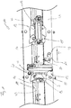
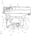
- einen Ausschnitt einer Transportvorrichtung mit zwei Transportsätteln in unterschiedlicher Position in Vorderansicht,
- Fig. 2
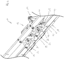
- den
Ausschnitt gemäß Figur 1 in Rückansicht, - Fig. 3
- eine Explosionsdarstellung eines Transportsattels mit Haltevorrichtung,
- Fig. 4
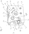
- einen Grundkörper des Aufnahmekörpers der Haltevorrichtung mit Rasthebel von hinten,
- Fig. 5
- den Grundkörper gemäß
Figur 4 von vorne, - Fig. 6
- den
Grundkörper gemäß Figur 5 ohne Rasthebel, - Fig. 7
- den Rasthebel von hinten,
- Fig. 8
- den Rasthebel von vorne,
- Fig. 9
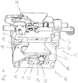
- den vollständigen Transportsattel von schräg vorne,
- Fig. 10
- die Darstellung gemäß
Figur 9 ohne Stützkörper des Transportsattels, - FIG 11
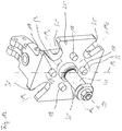
- das Drehorgan als Bestandteil des Befestigungskörpers von schräg vorne, und
- Fig. 12
- das Drehorgan gemäß
Figur 11 von hinten.
- Fig. 1
- a section of a transport device with two transport saddles in different positions in a front view,
- Fig. 2
- the cutout according to
Figure 1 in rear view, - Fig. 3
- an exploded view of a transport saddle with holding device,
- Fig. 4
- a base body of the receiving body of the holding device with locking lever from behind,
- Fig. 5
- the body according to
Figure 4 from the front, - Fig. 6
- the body according to
Figure 5 without locking lever, - Fig. 7
- the locking lever from behind,
- Fig. 8
- the locking lever from the front,
- Fig. 9
- the complete transport saddle diagonally from the front,
- Fig. 10
- the representation according to
Figure 9 without support body of the transport saddle, - FIG 11
- the rotating member as part of the fastening body obliquely from the front, and
- Fig. 12
- the rotating member according to
Figure 11 from behind.
Die in der Zeichnung nur ausschnittsweise dargestellte Transportvorrichtung dient zum Transportieren und Positionieren von entweideten Geflügelkörpern oder Teilen davon, wie z.B. Brustkappen oder Vorderhälften. Die Transportvorrichtung ist in entsprechender Weise auch für andere Produkte einsetzbar, die in unterschiedlichen Positionen entlang des Transportpfads positionierbar sein sollen.The transport device, shown only in part in the drawing, is used to transport and position de-grazed poultry carcasses or parts thereof, such as breast caps or front halves. The transport device can also be used in a corresponding manner for other products which should be able to be positioned in different positions along the transport path.
Die dargestellte Transportvorrichtung 10 ist zum Transportieren von entweideten Geflügelkörpern oder Teilen davon in Transportrichtung T entlang eines Transportpfads ausgebildet und eingerichtet. Entlang des Transportpfads können unterschiedliche Bearbeitungsstationen angeordnet sein, die eine unterschiedliche Positionierung der Geflügelkörper oder Teilen davon erfordern. Die Transportvorrichtung 10 umfasst eine endlos umlaufend angetriebene Transporteinheit 11 sowie mindestens einen daran befestigten Transportsattel 12 zum Halten und Positionieren der Geflügelkörper oder Teilen davon während des Transports, wobei zur Befestigung des Transportsattels 12 an der Transporteinheit 11 eine Haltevorrichtung 13 vorgesehen ist, die aus einem der Transporteinheit 11 zugeordneten Aufnahmekörper 14 und einem dem Transportsattel 12 zugeordneten Befestigungskörper 15 besteht, der lösbar mit dem Aufnahmekörper 14 verbunden und um eine Drehachse D drehbar im Aufnahmekörper 14 gelagert ist, wobei die Haltevorrichtung 13 eine Rasteinrichtung 16 umfasst, mittels der der Befestigungskörper 15 und damit der Transportsattel 12 in mindestens zwei unterschiedlichen Rastpositionen arretierbar ist, wobei die Rasteinrichtung 16 einen Rasthebel 17 und mindestens zwei Rastbolzen 18 umfasst, wobei der Rasthebel 17 um eine Schwenkachse S, die parallel zur Drehachse D ausgerichtet ist, schwenkbar an einem Grundkörper 19 des Aufnahmekörpers 14 angeordnet ist und aus einer Verriegelungsposition, in der der Rasthebel 17 mit einem Rastbolzen 18, der dem Befestigungskörper 15 zugeordnet ist, in Eingriff ist, in eine Freigabeposition, in der der Rasthebel 17 außer Eingriff mit einem Rastbolzen 18 des Befestigungskörpers 15 ist, und zurück bewegbar ist, wobei die Transportvorrichtung 10 ein erstes Betätigungsorgan 20 zum Betätigen des Rasthebels 17 mindestens aus der Verriegelungsposition in die Freigabeposition und ein zweites Betätigungsorgan 21 zum Drehen des Befestigungskörpers 15 in der Freigabeposition des Rasthebels 17 umfasst.The illustrated
Diese Transportvorrichtung 10 zeichnet sich erfindungsgemäß dadurch aus, dass die Rasteinrichtung 16 mindestens zwei magnetische Elemente 22, 23 umfasst, wobei ein erstes magnetisches Element 22 dem Aufnahmekörper 14 zugeordnet ist und ein zweites magnetisches Element 23 dem Rasthebel 17 zugeordnet ist, derart, dass sich jeweils ungleichnamige Pole des ersten magnetischen Elementes 22 und des zweiten magnetischen Elementes 23 zum Ziehen des Rasthebels 17 in die Verriegelungsposition einander anziehend gegenüberstehen.According to the invention, this
Die im Folgenden beschriebenen Merkmale und Weiterbildungen stellen für sich betrachtet oder in Kombination miteinander bevorzugte Ausführungsformen dar. Es wird ausdrücklich darauf hingewiesen, dass Merkmale, die in den Ansprüchen und/oder der Beschreibung und/oder der Zeichnung zusammengefasst oder in einer gemeinsamen Ausführungsform beschrieben sind, auch funktional eigenständig die weiter oben beschriebene Transportvorrichtung 10 weiterbilden können.The features and developments described below represent preferred embodiments considered alone or in combination with one another. It is expressly pointed out that features that are summarized in the claims and / or the description and / or the drawing or are described in a common embodiment , can also functionally independently develop the
Die umlaufend angetriebene Transporteinheit 11 ist um nicht explizit dargestellte Umlenk- und/oder Antriebselemente geführt. Die Drehachsen der Umlenk- und/oder Drehelemente können horizontal ausgerichtet sein, z.B. zur Bildung eines Obertrums und eines Untertrums. Die Drehachsen können aber auch jede andere Ausrichtung aufweisen, z.B. 45° zur horizontalen Ausrichtung. Vorzugsweise sind mehrere Transportsättel an der Transporteinheit angeordnet. Der Transportpfad erstreckt sich über die gesamte umlaufende Länge der Transporteinheit 11. Mittels eines Antriebsmittels ist die Transporteinheit 11 intermittierend oder kontinuierlich antreibbar. Bevorzugt ist das Antriebsmittel mit einer Steuerungseinrichtung verbunden. Die Haltevorrichtungen 13 und genauer die Aufnahmekörper 14 umfassen Befestigungsmittel 52, mit denen die Verbindung zur Transporteinheit 11 hergestellt wird.The circumferentially driven transport unit 11 is guided around deflection and / or drive elements that are not explicitly shown. The axes of rotation of the deflection and / or rotating elements can be aligned horizontally, e.g. to form an upper run and a lower run. However, the axes of rotation can also have any other orientation, e.g. 45 ° to the horizontal orientation. Several transport saddles are preferably arranged on the transport unit. The transport path extends over the entire circumferential length of the transport unit 11. The transport unit 11 can be driven intermittently or continuously by means of a drive means. The drive means is preferably connected to a control device. The holding
Jeder Transportsattel 12 kann einteilig oder mehrteilig ausgebildet sein. Der Transportsattel 12 umfasst den Befestigungskörper 15 und einen Stützkörper 24, der vorzugsweise lösbar mit dem Befestigungskörper 15 verbunden ist. Der Befestigungskörper 15 kann ebenfalls einteilig oder mehrteilig ausgebildet sein. Bevorzugt umfasst der Befestigungskörper 15 einen aus Kunststoff bestehenden Drehkörper 25 und einen aus Metall, z.B. Edelstahl, bestehenden Klemmkörper 26.Each
Vorzugsweise umfasst die Rasteinrichtung 16 ein drittes magnetisches Element 27, das dem Aufnahmekörper 14 zugeordnet und auf der dem ersten magnetischen Element 22 gegenüberliegenden Seite des Rasthebels 17 platziert ist, derart, dass sich gleichnamige Pole des zweiten magnetischen Elementes 23 und des dritten magnetischen Elementes 27 zum Drücken des Rasthebels 17 in die Verriegelungsposition einander abstoßend gegenüberstehen. Beispielsweise stehen sich der Nordpol des ersten magnetischen Elementes 22 und der Südpol des zweiten magnetischen Elementes 23 unmittelbar oder gering beabstandet zueinander gegenüber, während sich der Nordpol des zweiten magnetischen Elementes 23 und der Nordpol des dritten magnetischen Elements 27 unmittelbar oder gering beabstandet zueinander gegenüberstehen.The latching
Der Grundkörper 19 des Aufnahmekörpers 14 weist an seinem in Transportrichtung T nachlaufenden Ende E auf der dem Befestigungskörper 15 zugewandten Seite eine Vertiefung 28 auf (siehe insbesondere
Das dritte magnetische Element 27 ist in der Vertiefung 28 des Grundkörpers 19 im Bereich einer Seitenwand 51 positioniert, derart, dass der Rasthebel 17 mit seinem Vorsprung 29, in dem sich das zweite magnetische Element 23 befindet, sandwichartig zwischen dem ersten und dem dritten magnetischen Element 22, 27 angeordnet ist. Die magnetischen Elemente 22, 23, 27 können auf den Grundkörper 19 bzw. den Rasthebel 17 aufgesetzt sein. Bevorzugt ist mindestens das dritte magnetische Element in den Grundkörper 19 eingelassen.The third
In einer nicht dargestellten Ausführungsform ist die Rückwand 33 des Grundkörpers 19 und damit auch die Rückwand 30 der Vertiefung 28 vollständig geschlossen ausgebildet. In der dargestellten Variante weist der Grundkörper 19 im Bereich der Vertiefung 28 einen Durchbruch 31 auf, dessen Hauptausrichtung parallel zur Schwenkachse S und Drehachse D ausgerichtet ist, derart, dass der Vorsprung 29 des Rasthebels 17 mit seinem freien Ende mindestens abschnittsweise in diesen Durchbruch 31 eintaucht, derart, dass eine Seitenwand 32 des Durchbruchs 31 in Ergänzung zum Rastbolzen 18 als Anschlag für den Rasthebel 17 in seiner Verriegelungsposition ausgebildet ist. Der Durchbruch 31 ist vom nachlaufenden Ende E beabstandet ausgebildet, so dass ein Verbindungssteg 34 gebildet ist, an dem bzw. auf dem das erste magnetische Element 22 angeordnet ist.In an embodiment not shown, the
Dem Befestigungskörper 15 ist der Drehkörper 25 in Form eines Malteserkreuzes zugeordnet, das zum einen vier im Bereich des Umfangs um 90° versetzt zueinander angeordnete Ausnehmungen 35 zum Eingreifen des Betätigungsorgans 21 zum Drehen des Befestigungskörpers 15, und zum anderen auf der dem Aufnahmekörper 14 zugewandten Seite mindestens vier um 90° versetzt zueinander angeordnete Rastbolzen 18, die mit dem Rasthebel 17 in Wirkverbindung bringbar sind, aufweist (siehe insbesondere
Die bevorzugte Ausbildung des Rasthebels 17 ist insbesondere den
Die Transporteinheit 11 umfasst bevorzugt eine Transportkette 43. Entlang der Transportkette 43 ist mindestens abschnittsweise mindestens eine Führungsschiene 44 angeordnet, auf der der Aufnahmekörper 14 der Haltevorrichtung 13 mit einer in dem Grundkörper 19 ausgebildeten Nut 45 geführt ist. Besonders bevorzugt sind zwei beabstandet zueinander angeordnete Führungsschienen 44, 46 mindestens abschnittsweise entlang der Transportkette 43 angeordnet, zwischen denen der Grundkörper 19 mit entsprechenden Nuten 45, 47 geführt ist. In der dargestellten Ausführungsform ist an einer Führungsschiene 46 das Betätigungsorgan 20 zum Betätigen des Rasthebels 17 und an der anderen Führungsschiene 44 das Betätigungsorgan 21 zum Drehen des Befestigungskörpers 15 angeordnet. Es besteht jedoch auch die Möglichkeit einer umgekehrten Anbringung. Die Betätigungsorgane 20, 21 können auch an einer gemeinsamen Führungsschiene 44 oder 46 angeordnet sein. Optional können die Betätigungsorgane 20, 21 auch separat von den Führungsschienen 44, 46 angeordnet sein.The transport unit 11 preferably comprises a
Vorzugsweise ist das Betätigungsorgan 21 zum Drehen des Befestigungskörpers 15 in Transportrichtung T der Transporteinheit hinter dem Betätigungsorgan 20 zum Betätigen des Rasthebels 17 angeordnet. "Hinter" bezieht sich dabei nicht auf die konstruktive Anbringung, sondern auf die Position, in der die Betätigungsorgane 20, 21 in Eingriff mit dem Rasthebel 17 bzw. dem Befestigungskörper 15 kommen. Das Betätigungsorgan 20 zum Schwenken des Rasthebels 17 kann ein einfacher Bolzen, Anschlag oder dergleichen sein, der ortsfest an der Führungsschiene 46 angeordnet ist und im Transportweg der Betätigungsnase 38 des Rasthebels 17 liegt, derart, dass der Rasthebel 17 durch das Transportieren entlang des Transportpfads beim Passieren des Betätigungsorgan 20 außer Eingriff mit dem Rastbolzen 18 geschwenkt wird. In einer besonders bevorzugte Ausführungsform ragt der Rasthebel 17 mit der Betätigungsnase 38 über den Grundkörper 19 des Aufnahmekörpers 14 hinaus, derart, dass das Betätigungsorgan 20 zum Betätigen des Rasthebels 17 beim Passieren des Transportsattels 12 mit der Betätigungsnase 38 des Rasthebels 17 in Wirkverbindung tritt. Das Betätigungsorgan 20 kann auch eine frei drehbare Rolle 48 oder dergleichen sein. In anderen Ausführungsformen, bei denen der Rasthebel 17 über eine längere Distanz in der Freigabeposition gehalten werden soll/muss, beispielsweise, um den Befestigungskörper 15 mittels des Drehkörpers 25 um einen größeren Winkelbetrag zu drehen, kann das Betätigungsorgan 20 z.B. auch eine sich in Transportrichtung T erstreckende Schiene oder dergleichen sein. Das Betätigungsorgan 20 kann auch verstellbar an der Führungsschiene 46 angeordnet sein.The
Das Betätigungsorgan 21 zum Drehen des Befestigungskörpers 15 kann ein einfaches Winkelelement 49 oder dergleichen sein, wobei ein Arm 50 des Winkelelementes 49 in den Transportweg des Drehkörpers 25 ragt, derart, dass der Drehkörper 25 beim Passieren des Transportsattels 12 mit einer Ausnehmung 35 in Eingriff mit dem Arm 50 kommt. Der Weitertransport in Transportrichtung T führt dann zum Drehen des Befestigungskörpers 15, im gezeigten Ausführungsbeispiel um 90°. In Transportrichtung T können hintereinander auch zwei oder mehr solcher Betätigungsorgane 21 angeordnet sein, um in Eingriff mit der jeweils nächsten Ausnehmung 35 des Drehkörpers 25 zu kommen.The actuating
Die magnetischen Elemente 22, 23, 27 sind mindestens teilweise als Stabmagnete ausgebildet, wobei die Stabmagnete mit ihrer Längsachse in Transportrichtung T ausgerichtet sind. Vorzugsweise sind die Stabmagnete 22, 23, 27 mit ihren Längsachsen im Wesentlichen fluchtend zueinander ausgerichtet. In der gezeigten Ausführungsform sind mindestens das erste und das dritte magnetische Element 22, 27 als Stabmagnet ausgebildet. Bevorzugt ist auch das zweite magnetische Element 23 als Stabmagnet ausgebildet. Die Stabmagnete sind mindestens teilweise in Sacklöchern angeordnet, wobei die offenen Seiten der Sacklöcher optional mittels einer Abdeckung verschlossen sind, derart, dass die innerhalb der Sacklöcher befindlichen Stabmagnete vollständig gegenüber der Umgebung abgeschirmt sind. Die magnetischen Elemente 22, 23, 27 umfassen jeweils Dauermagnete und/oder Elektromagnete. Besonders bevorzugt sind die Dauermagnete als Neodym-Magnete ausgebildet. Noch weiter bevorzugt handelt es sich um vernickelte Neodym-Magnete.The
Das Funktionsprinzip der Rasteinrichtung 16 wird anhand der
Beim freien Drehen läuft ein Rastbolzen 18 auf der Innenseite I des Rasthebels 17. Dabei bzw. dadurch wird der Rasthebel 17 weiter in der Freigabeposition gehalten. Sobald der Rastbolzen 18 in den Bereich der Ausnehmung 36 des Rasthebels 17 kommt, nach etwa 90°-Drehung des Drehkörpers 25, schnappt der Rasthebel 17 durch die Anziehungskraft der ersten und zweiten magnetischen Elemente 22, 23 zurück in die Verriegelungsposition. Die abstoßende Wirkung der zweiten und dritten magnetischen Elemente 23, 27 wird diese Bewegung des Rasthebels 17 unterstützt. Damit ist der Transportsattel 12 mit seiner Hauptachse horizontal ausgerichtet.When it is freely rotated, a locking
Claims (13)
- Transport apparatus (10), configured and adapted for transporting eviscerated poultry bodies or parts thereof in a direction of transport T along a transport path, along which different processing stations can be arranged, comprising a transport unit (11) driven in a continuously revolving manner and at least one transport saddle (12) fastened thereto for holding and positioning the poultry bodies or parts thereof during transport, wherein a holding apparatus (13) is provided for fastening the transport saddle (12) to the transport unit (11), which holding apparatus consists of a receptacle body (14) associated with the transport unit (11) and a fastening body (15) associated with the transport saddle (12), which fastening body is releasably connected to the receptacle body (14) and is mounted in the receptacle body (14) so as to be rotatable about an axis of rotation D, wherein the holding apparatus (13) comprises a latching device (16) by means of which the fastening body (15) and thus the transport saddle (12) can be locked in at least two different latching positions, wherein the latching device (16) comprises a latching lever (17) and at least two latching bolts (18), wherein the latching lever (17) is arranged on a main body (19) of the receptacle body (14) so as to be pivotable about a pivot axis S, which is oriented parallel to the axis of rotation D, and is movable from a locking position, in which the latching lever (17) is in engagement with a latching bolt (18) associated with the fastening body (15), into a release position, in which the latching lever (17) is out of engagement with a latching bolt (18) of the fastening body (15), and back, wherein the transport apparatus (10) comprises a first actuating member (20) for actuating the latching lever (17) at least from the locking position into the release position and a second actuating member (21) for rotating the fastening body (15) in the release position of the latching lever (17), characterised in that the latching device (16) comprises at least two magnetic elements (22, 23), wherein a first magnetic element (22) is associated with the receptacle body (14) and a second magnetic element (23) is associated with the latching lever (17), such that unlike poles of the first magnetic element (22) and of the second magnetic element (23) are located opposite one another so as to attract one another and pull the latching lever (17) into the locking position.
- Transport apparatus (10) according to claim 1, characterised in that the latching device (16) comprises a third magnetic element (27) which is associated with the receptacle body (14) and is positioned on the side of the latching lever (17) opposite the first magnetic element (22), such that like poles of the second magnetic element (23) and of the third magnetic element (27) are located opposite one another so as to repel one another and push the latching lever (17) into the locking position.
- Transport apparatus (10) according to claim 1 or 2, characterised in that the main body (19) of the receptacle body (14) has a depression (28) at its trailing end (E) in the direction of transport T on the side facing the fastening body (15), into which depression the latching lever (17) with a protrusion (29) dips at least in part, wherein the first magnetic element (22) is positioned in the depression (28) of the main body (19) in the region of a rear wall (30) and the second magnetic element (23) is positioned in the protrusion (29) of the latching lever (17).
- Transport apparatus (10) according to claim 2 or 3, characterised in that the third magnetic element (27) is positioned in the depression (28) of the main body (19) in the region of a side wall, such that the latching lever (17) is arranged with its protrusion (29), in which the second magnetic element (23) is located, between the first and the third magnetic element (22 and 27) in the manner of a sandwich.
- Transport apparatus (10) according to claim 3 or 4, characterised in that the main body (19) has an opening (31) in the region of the depression (28), the main orientation of which opening is oriented parallel to the pivot axis S and the axis of rotation D, such that the protrusion (29) of the latching lever (17) dips with its free end at least in part into this opening (31), such that a side wall (32) of the opening (31), in addition to the latching bolt (18), is configured as an abutment for the latching lever (17) in its locking position.
- Transport apparatus (10) according to one or more of claims 1 to 5, characterised in that there is associated with the fastening body (15) a rotating body (25) in the form of a Maltese cross, which has on the one hand four recesses (35) arranged offset relative to one another by 90° in the region of the circumference for the engagement of the actuating member (21) for rotating the fastening body (15), and on the other hand, on the side facing the receptacle body (14), at least four latching bolts (18) arranged offset relative to one another by 90°, which latching bolts can be brought into operative connection with the latching lever (17).
- Transport apparatus (10) according to claim 6, characterised in that the latching lever (17) has on its inner side (I) facing the axis of rotation D a recess (36) for receiving a latching bolt (18).
- Transport apparatus (10) according to one or more of claims 1 to 7, characterised in that the transport unit (11) comprises a transport chain (43), and at least one guide rail (44, 46) is arranged along the transport chain (43) at least in some regions, on which guide rail the receptacle body (14) of the holding apparatus (13) is guided with a groove (45, 47) formed in the main body (19).
- Transport apparatus (10) according to claim 8, characterised in that two guide rails (44, 46) arranged spaced apart from one another are arranged along the transport chain (43) at least in some regions, between which guide rails the main body (19) is guided with corresponding grooves (45, 47), wherein the actuating member (20) for actuating the latching lever (17) is arranged on one guide rail (46) and the actuating member (21) for rotating the fastening body (15) is arranged on the other guide rail (44).
- Transport apparatus (10) according to one or more of claims 1 to 9, characterised in that the actuating member (21) for rotating the fastening body (15) is arranged behind the actuating member (20) for actuating the latching lever (17) in the direction of transport T of the transport unit (11).
- Transport apparatus (10) according to one or more of claims 1 to 10, characterised in that the latching lever (17) projects with an actuating lug (38) beyond the main body (19) of the receptacle body (14), such that the actuating member (20) for actuating the latching lever (17) enters into operative connection with the actuating lug (38) of the latching lever (17) as the transport saddle (12) passes.
- Transport apparatus (10) according to one or more of claims 1 to 11, characterised in that at least some of the magnetic elements (22, 23, 27) are in the form of bar magnets, wherein the bar magnets are oriented with their longitudinal axis in the direction of transport T.
- Transport apparatus (10) according to claim 12, characterised in that at least some of the bar magnets are arranged in blind holes, wherein the open sides of the blind holes are closed by means of a cover, such that the bar magnets inside the blind holes are completely shielded relative to the surroundings.
Priority Applications (11)
| Application Number | Priority Date | Filing Date | Title |
|---|---|---|---|
| ES19171118T ES2906400T3 (en) | 2019-04-25 | 2019-04-25 | Transport device for transporting eviscerated poultry carcasses or parts thereof |
| DK19171118.3T DK3729968T3 (en) | 2019-04-25 | 2019-04-25 | Transport device for transporting cleaned poultry carcases or parts thereof |
| PL19171118T PL3729968T3 (en) | 2019-04-25 | 2019-04-25 | Transport apparatus for transporting eviscerated poultry bodies or parts thereof |
| EP19171118.3A EP3729968B1 (en) | 2019-04-25 | 2019-04-25 | Transport apparatus for transporting eviscerated poultry bodies or parts thereof |
| CA3134376A CA3134376C (en) | 2019-04-25 | 2020-04-22 | Transport device for transporting eviscerated poultry carcasses or parts thereof |
| PCT/EP2020/061205 WO2020216787A1 (en) | 2019-04-25 | 2020-04-22 | Transport device for transporting eviscerated poultry carcasses or parts thereof |
| KR1020217035300A KR102434683B1 (en) | 2019-04-25 | 2020-04-22 | A transport device for transporting poultry carcasses or parts thereof from which the intestines have been removed |
| BR112021020714-7A BR112021020714B1 (en) | 2019-04-25 | 2020-04-22 | TRANSPORT EQUIPMENT FOR TRANSPORTING EVISCERATED POULTRY CARCASSES OR PARTS THEREOF |
| US17/605,131 US11484037B2 (en) | 2019-04-25 | 2020-04-22 | Transport device for transporting eviscerated poultry carcasses or parts thereof |
| JP2021562826A JP7168797B2 (en) | 2019-04-25 | 2020-04-22 | Transfer device for transferring eviscerated poultry carcasses or parts thereof |
| CN202080029747.3A CN113784621B (en) | 2019-04-25 | 2020-04-22 | Conveying device for conveying eviscerated poultry carcasses or parts thereof |
Applications Claiming Priority (1)
| Application Number | Priority Date | Filing Date | Title |
|---|---|---|---|
| EP19171118.3A EP3729968B1 (en) | 2019-04-25 | 2019-04-25 | Transport apparatus for transporting eviscerated poultry bodies or parts thereof |
Publications (2)
| Publication Number | Publication Date |
|---|---|
| EP3729968A1 EP3729968A1 (en) | 2020-10-28 |
| EP3729968B1 true EP3729968B1 (en) | 2021-12-29 |
Family
ID=66286234
Family Applications (1)
| Application Number | Title | Priority Date | Filing Date |
|---|---|---|---|
| EP19171118.3A Active EP3729968B1 (en) | 2019-04-25 | 2019-04-25 | Transport apparatus for transporting eviscerated poultry bodies or parts thereof |
Country Status (11)
| Country | Link |
|---|---|
| US (1) | US11484037B2 (en) |
| EP (1) | EP3729968B1 (en) |
| JP (1) | JP7168797B2 (en) |
| KR (1) | KR102434683B1 (en) |
| CN (1) | CN113784621B (en) |
| BR (1) | BR112021020714B1 (en) |
| CA (1) | CA3134376C (en) |
| DK (1) | DK3729968T3 (en) |
| ES (1) | ES2906400T3 (en) |
| PL (1) | PL3729968T3 (en) |
| WO (1) | WO2020216787A1 (en) |
Citations (6)
| Publication number | Priority date | Publication date | Assignee | Title |
|---|---|---|---|---|
| EP0935922A1 (en) | 1998-02-17 | 1999-08-18 | Systemate Holland B.V. | Rotary shackle with position lock |
| US8789684B2 (en) | 2010-04-19 | 2014-07-29 | Foodmate Bv | Rotatable article support for a conveyor |
| WO2015065190A1 (en) | 2013-11-01 | 2015-05-07 | Foodmate B.V. | Method and system for automatically deboning poultry breast caps containing meat and a skeletal structure to obtain breast fillets therefrom |
| US9185918B2 (en) | 2011-01-26 | 2015-11-17 | Foodmate Bv | Meat processing equipment having improved yieldable arresting means |
| US9615591B1 (en) | 2015-11-20 | 2017-04-11 | Foodmate B.V. | Meat stripper with articulating stripper plate assembly |
| WO2019001728A1 (en) | 2017-06-30 | 2019-01-03 | Nordischer Maschinenbau Rud. Baader Gmbh + Co. Kg | Conveying arrangement and method for conveying poultry carcasses, and apparatus and method for filleting poultry carcasses |
Family Cites Families (18)
| Publication number | Priority date | Publication date | Assignee | Title |
|---|---|---|---|---|
| US4780930A (en) * | 1987-08-31 | 1988-11-01 | Fabricated Products | Poultry cutter with a rotatable arbor and guide means |
| DE58902088D1 (en) * | 1989-01-28 | 1992-09-24 | Nordischer Maschinenbau | METHOD FOR MACHINING THE MEAT FROM POULTRY BODIES AND DEVICE FOR CARRYING OUT THE METHOD. |
| US5045022A (en) * | 1990-01-31 | 1991-09-03 | Hazenbroek Jacobus E | Adjustable poultry breast filleting system |
| DE4134621C1 (en) * | 1991-10-19 | 1992-10-29 | Nordischer Maschinenbau Rud. Baader Gmbh + Co Kg, 2400 Luebeck, De | |
| NL1028142C2 (en) * | 2005-01-28 | 2006-07-31 | Stork Pmt | Transport device for slaughtered poultry. |
| NL1028561C2 (en) | 2005-03-17 | 2006-09-20 | Stork Pmt | Processing of carcass parts of slaughtered poultry. |
| DK1956919T3 (en) | 2005-12-09 | 2016-01-18 | Marel Stork Poultry Proc Bv | A method and apparatus for processing a carcass part of slaughtered poultry |
| NL2001993C (en) * | 2008-09-18 | 2010-03-19 | Meyn Food Proc Technology Bv | Method and apparatus for processing poultry or a part thereof. |
| US8757354B2 (en) * | 2010-04-19 | 2014-06-24 | Foodmate Bv | Turning block alignment |
| DE102010047660B4 (en) | 2010-09-30 | 2016-09-01 | Nordischer Maschinenbau Rud. Baader Gmbh + Co. Kg | Apparatus and method for completely detaching at least a portion of the breast cartilage from a poultry carcass freed from the breast meat |
| EP2606735B1 (en) | 2011-12-23 | 2014-10-29 | Nordischer Maschinenbau Rud. Baader GmbH + Co. KG | Device and method for complete separation of a breast fillet partially separated from the carcass of a gutted poultry body |
| NL2008729C2 (en) | 2012-04-27 | 2013-10-29 | Meyn Food Proc Technology Bv | A method and apparatus for processing a poultry carcass part. |
| US9078453B2 (en) * | 2013-11-01 | 2015-07-14 | Foodmate B.V. | Method and system for automatically deboning poultry breast caps containing meat and a skeletal structure to obtain breast fillets therefrom |
| DK3102040T3 (en) | 2014-02-07 | 2018-09-24 | Linco Food Systems As | Positioning device for positioning in the transport direction along a transport section in a series of transported poultry and a method comprising the positioning, for removing the upper thigh meat from the poultry. |
| NL2012386B1 (en) * | 2014-03-10 | 2015-11-26 | Marel Stork Poultry Proc Bv | Device and method for changing the orientation of slaughter products. |
| NL2015436B1 (en) * | 2015-09-14 | 2017-04-19 | Foodmate Bv | Apparatus, system and method for removing furculae from poultry breast caps. |
| EP3516964A1 (en) * | 2018-01-26 | 2019-07-31 | Nordischer Maschinenbau Rud. Baader Gmbh + Co Kg | Holding device for holding eviscerated poultry carcasses or parts thereof during machining in an apparatus for the processing of eviscerated carcasses or parts thereof |
| NL2020679B1 (en) * | 2018-03-28 | 2019-10-07 | Meyn Food Processing Tech Bv | System for placement of a supply of poultry front halves in an ordered sequence in a processing line |
-
2019
- 2019-04-25 ES ES19171118T patent/ES2906400T3/en active Active
- 2019-04-25 PL PL19171118T patent/PL3729968T3/en unknown
- 2019-04-25 EP EP19171118.3A patent/EP3729968B1/en active Active
- 2019-04-25 DK DK19171118.3T patent/DK3729968T3/en active
-
2020
- 2020-04-22 CA CA3134376A patent/CA3134376C/en active Active
- 2020-04-22 US US17/605,131 patent/US11484037B2/en active Active
- 2020-04-22 WO PCT/EP2020/061205 patent/WO2020216787A1/en active Application Filing
- 2020-04-22 BR BR112021020714-7A patent/BR112021020714B1/en active IP Right Grant
- 2020-04-22 JP JP2021562826A patent/JP7168797B2/en active Active
- 2020-04-22 KR KR1020217035300A patent/KR102434683B1/en active IP Right Grant
- 2020-04-22 CN CN202080029747.3A patent/CN113784621B/en active Active
Patent Citations (6)
| Publication number | Priority date | Publication date | Assignee | Title |
|---|---|---|---|---|
| EP0935922A1 (en) | 1998-02-17 | 1999-08-18 | Systemate Holland B.V. | Rotary shackle with position lock |
| US8789684B2 (en) | 2010-04-19 | 2014-07-29 | Foodmate Bv | Rotatable article support for a conveyor |
| US9185918B2 (en) | 2011-01-26 | 2015-11-17 | Foodmate Bv | Meat processing equipment having improved yieldable arresting means |
| WO2015065190A1 (en) | 2013-11-01 | 2015-05-07 | Foodmate B.V. | Method and system for automatically deboning poultry breast caps containing meat and a skeletal structure to obtain breast fillets therefrom |
| US9615591B1 (en) | 2015-11-20 | 2017-04-11 | Foodmate B.V. | Meat stripper with articulating stripper plate assembly |
| WO2019001728A1 (en) | 2017-06-30 | 2019-01-03 | Nordischer Maschinenbau Rud. Baader Gmbh + Co. Kg | Conveying arrangement and method for conveying poultry carcasses, and apparatus and method for filleting poultry carcasses |
Also Published As
| Publication number | Publication date |
|---|---|
| BR112021020714B1 (en) | 2022-08-23 |
| WO2020216787A1 (en) | 2020-10-29 |
| KR20210136144A (en) | 2021-11-16 |
| CA3134376A1 (en) | 2020-10-29 |
| DK3729968T3 (en) | 2022-03-28 |
| US20220142189A1 (en) | 2022-05-12 |
| EP3729968A1 (en) | 2020-10-28 |
| JP2022525240A (en) | 2022-05-11 |
| PL3729968T3 (en) | 2022-04-11 |
| CN113784621A (en) | 2021-12-10 |
| CA3134376C (en) | 2022-05-17 |
| US11484037B2 (en) | 2022-11-01 |
| KR102434683B1 (en) | 2022-08-19 |
| JP7168797B2 (en) | 2022-11-09 |
| BR112021020714A2 (en) | 2022-01-04 |
| ES2906400T3 (en) | 2022-04-18 |
| CN113784621B (en) | 2022-09-06 |
Similar Documents
| Publication | Publication Date | Title |
|---|---|---|
| EP3286118B1 (en) | Container gripper and transporting device for transporting containers | |
| EP2858793B1 (en) | Gripper | |
| EP1856417B1 (en) | Heavy-duty mounting for connecting two components | |
| DE102014111564B4 (en) | Gripping arm for containers, control cams, storage unit and gripping device | |
| EP2621838B1 (en) | Roller-way with torque bracket | |
| EP1042206B1 (en) | Device for receiving and/or conveying flat products | |
| EP2546546B1 (en) | Device for guiding supply lines | |
| EP3433191A1 (en) | Carrying apparatus and cam control shaft for gripping devices | |
| EP3729968B1 (en) | Transport apparatus for transporting eviscerated poultry bodies or parts thereof | |
| EP0461372B1 (en) | Turning device for work pieces, especially for turning over bushes | |
| EP2031156B1 (en) | Reset mechanism for a door handle | |
| WO1998036385A1 (en) | Conveying device for individual sheets | |
| EP2578891B1 (en) | Adapter | |
| DE102017108928B4 (en) | container gripper | |
| EP3064454B1 (en) | Conveyor chain for transporting items and transport system with conveyor chain | |
| EP3693618B1 (en) | Assembly for multiple quick release and multiple quick opening | |
| DE19927728C1 (en) | Gripper mechanism for handling postal mail has a manual operating unit inserted into the claw drive to open the claw easily when the machine is at rest without risk of injury | |
| DE102009023718B4 (en) | mounter | |
| DE102007046360B4 (en) | Assembly unit with integrated horizontal conveyor for small parts | |
| DE202023100463U1 (en) | Trap protection device for a roller conveyor and roller conveyor | |
| EP3024356B1 (en) | Locking system | |
| DE102010019578A1 (en) | Door Opener | |
| DE102010018177A1 (en) | Door Opener | |
| DE102018221357A1 (en) | Transport device, transport system and method for transporting objects | |
| DE102009000456A1 (en) | Deflector for hanging conveyor belt for transport of articles of clothing, has swivel guide provided for support element, where swivel guide is rigid in transport direction and is bendably formed transverse to transport direction |
Legal Events
| Date | Code | Title | Description |
|---|---|---|---|
| PUAI | Public reference made under article 153(3) epc to a published international application that has entered the european phase |
Free format text: ORIGINAL CODE: 0009012 |
|
| STAA | Information on the status of an ep patent application or granted ep patent |
Free format text: STATUS: THE APPLICATION HAS BEEN PUBLISHED |
|
| AK | Designated contracting states |
Kind code of ref document: A1 Designated state(s): AL AT BE BG CH CY CZ DE DK EE ES FI FR GB GR HR HU IE IS IT LI LT LU LV MC MK MT NL NO PL PT RO RS SE SI SK SM TR |
|
| AX | Request for extension of the european patent |
Extension state: BA ME |
|
| STAA | Information on the status of an ep patent application or granted ep patent |
Free format text: STATUS: REQUEST FOR EXAMINATION WAS MADE |
|
| 17P | Request for examination filed |
Effective date: 20210406 |
|
| RBV | Designated contracting states (corrected) |
Designated state(s): AL AT BE BG CH CY CZ DE DK EE ES FI FR GB GR HR HU IE IS IT LI LT LU LV MC MK MT NL NO PL PT RO RS SE SI SK SM TR |
|
| GRAP | Despatch of communication of intention to grant a patent |
Free format text: ORIGINAL CODE: EPIDOSNIGR1 |
|
| STAA | Information on the status of an ep patent application or granted ep patent |
Free format text: STATUS: GRANT OF PATENT IS INTENDED |
|
| INTG | Intention to grant announced |
Effective date: 20210922 |
|
| GRAS | Grant fee paid |
Free format text: ORIGINAL CODE: EPIDOSNIGR3 |
|
| GRAA | (expected) grant |
Free format text: ORIGINAL CODE: 0009210 |
|
| STAA | Information on the status of an ep patent application or granted ep patent |
Free format text: STATUS: THE PATENT HAS BEEN GRANTED |
|
| AK | Designated contracting states |
Kind code of ref document: B1 Designated state(s): AL AT BE BG CH CY CZ DE DK EE ES FI FR GB GR HR HU IE IS IT LI LT LU LV MC MK MT NL NO PL PT RO RS SE SI SK SM TR |
|
| REG | Reference to a national code |
Ref country code: GB Ref legal event code: FG4D Free format text: NOT ENGLISH |
|
| REG | Reference to a national code |
Ref country code: CH Ref legal event code: EP |
|
| REG | Reference to a national code |
Ref country code: AT Ref legal event code: REF Ref document number: 1458007 Country of ref document: AT Kind code of ref document: T Effective date: 20220115 |
|
| REG | Reference to a national code |
Ref country code: IE Ref legal event code: FG4D Free format text: LANGUAGE OF EP DOCUMENT: GERMAN |
|
| REG | Reference to a national code |
Ref country code: DE Ref legal event code: R096 Ref document number: 502019003084 Country of ref document: DE |
|
| REG | Reference to a national code |
Ref country code: DK Ref legal event code: T3 Effective date: 20220322 |
|
| REG | Reference to a national code |
Ref country code: SE Ref legal event code: TRGR |
|
| REG | Reference to a national code |
Ref country code: NL Ref legal event code: FP |
|
| REG | Reference to a national code |
Ref country code: LT Ref legal event code: MG9D |
|
| REG | Reference to a national code |
Ref country code: ES Ref legal event code: FG2A Ref document number: 2906400 Country of ref document: ES Kind code of ref document: T3 Effective date: 20220418 |
|
| PG25 | Lapsed in a contracting state [announced via postgrant information from national office to epo] |
Ref country code: RS Free format text: LAPSE BECAUSE OF FAILURE TO SUBMIT A TRANSLATION OF THE DESCRIPTION OR TO PAY THE FEE WITHIN THE PRESCRIBED TIME-LIMIT Effective date: 20211229 Ref country code: LT Free format text: LAPSE BECAUSE OF FAILURE TO SUBMIT A TRANSLATION OF THE DESCRIPTION OR TO PAY THE FEE WITHIN THE PRESCRIBED TIME-LIMIT Effective date: 20211229 Ref country code: FI Free format text: LAPSE BECAUSE OF FAILURE TO SUBMIT A TRANSLATION OF THE DESCRIPTION OR TO PAY THE FEE WITHIN THE PRESCRIBED TIME-LIMIT Effective date: 20211229 Ref country code: BG Free format text: LAPSE BECAUSE OF FAILURE TO SUBMIT A TRANSLATION OF THE DESCRIPTION OR TO PAY THE FEE WITHIN THE PRESCRIBED TIME-LIMIT Effective date: 20220329 |
|
| PG25 | Lapsed in a contracting state [announced via postgrant information from national office to epo] |
Ref country code: NO Free format text: LAPSE BECAUSE OF FAILURE TO SUBMIT A TRANSLATION OF THE DESCRIPTION OR TO PAY THE FEE WITHIN THE PRESCRIBED TIME-LIMIT Effective date: 20220329 Ref country code: LV Free format text: LAPSE BECAUSE OF FAILURE TO SUBMIT A TRANSLATION OF THE DESCRIPTION OR TO PAY THE FEE WITHIN THE PRESCRIBED TIME-LIMIT Effective date: 20211229 Ref country code: HR Free format text: LAPSE BECAUSE OF FAILURE TO SUBMIT A TRANSLATION OF THE DESCRIPTION OR TO PAY THE FEE WITHIN THE PRESCRIBED TIME-LIMIT Effective date: 20211229 Ref country code: GR Free format text: LAPSE BECAUSE OF FAILURE TO SUBMIT A TRANSLATION OF THE DESCRIPTION OR TO PAY THE FEE WITHIN THE PRESCRIBED TIME-LIMIT Effective date: 20220330 |
|
| PG25 | Lapsed in a contracting state [announced via postgrant information from national office to epo] |
Ref country code: SM Free format text: LAPSE BECAUSE OF FAILURE TO SUBMIT A TRANSLATION OF THE DESCRIPTION OR TO PAY THE FEE WITHIN THE PRESCRIBED TIME-LIMIT Effective date: 20211229 Ref country code: SK Free format text: LAPSE BECAUSE OF FAILURE TO SUBMIT A TRANSLATION OF THE DESCRIPTION OR TO PAY THE FEE WITHIN THE PRESCRIBED TIME-LIMIT Effective date: 20211229 Ref country code: RO Free format text: LAPSE BECAUSE OF FAILURE TO SUBMIT A TRANSLATION OF THE DESCRIPTION OR TO PAY THE FEE WITHIN THE PRESCRIBED TIME-LIMIT Effective date: 20211229 Ref country code: PT Free format text: LAPSE BECAUSE OF FAILURE TO SUBMIT A TRANSLATION OF THE DESCRIPTION OR TO PAY THE FEE WITHIN THE PRESCRIBED TIME-LIMIT Effective date: 20220429 Ref country code: EE Free format text: LAPSE BECAUSE OF FAILURE TO SUBMIT A TRANSLATION OF THE DESCRIPTION OR TO PAY THE FEE WITHIN THE PRESCRIBED TIME-LIMIT Effective date: 20211229 Ref country code: CZ Free format text: LAPSE BECAUSE OF FAILURE TO SUBMIT A TRANSLATION OF THE DESCRIPTION OR TO PAY THE FEE WITHIN THE PRESCRIBED TIME-LIMIT Effective date: 20211229 |
|
| REG | Reference to a national code |
Ref country code: DE Ref legal event code: R026 Ref document number: 502019003084 Country of ref document: DE |
|
| PG25 | Lapsed in a contracting state [announced via postgrant information from national office to epo] |
Ref country code: IS Free format text: LAPSE BECAUSE OF FAILURE TO SUBMIT A TRANSLATION OF THE DESCRIPTION OR TO PAY THE FEE WITHIN THE PRESCRIBED TIME-LIMIT Effective date: 20220429 |
|
| PLBI | Opposition filed |
Free format text: ORIGINAL CODE: 0009260 |
|
| PLAX | Notice of opposition and request to file observation + time limit sent |
Free format text: ORIGINAL CODE: EPIDOSNOBS2 |
|
| PG25 | Lapsed in a contracting state [announced via postgrant information from national office to epo] |
Ref country code: AL Free format text: LAPSE BECAUSE OF FAILURE TO SUBMIT A TRANSLATION OF THE DESCRIPTION OR TO PAY THE FEE WITHIN THE PRESCRIBED TIME-LIMIT Effective date: 20211229 |
|
| 26 | Opposition filed |
Opponent name: MAREL POULTRY B.V. Effective date: 20220928 |
|
| REG | Reference to a national code |
Ref country code: CH Ref legal event code: PL |
|
| REG | Reference to a national code |
Ref country code: BE Ref legal event code: MM Effective date: 20220430 |
|
| PG25 | Lapsed in a contracting state [announced via postgrant information from national office to epo] |
Ref country code: MC Free format text: LAPSE BECAUSE OF FAILURE TO SUBMIT A TRANSLATION OF THE DESCRIPTION OR TO PAY THE FEE WITHIN THE PRESCRIBED TIME-LIMIT Effective date: 20211229 Ref country code: LU Free format text: LAPSE BECAUSE OF NON-PAYMENT OF DUE FEES Effective date: 20220425 Ref country code: LI Free format text: LAPSE BECAUSE OF NON-PAYMENT OF DUE FEES Effective date: 20220430 Ref country code: CH Free format text: LAPSE BECAUSE OF NON-PAYMENT OF DUE FEES Effective date: 20220430 |
|
| PLAK | Information related to reply of patent proprietor to notice(s) of opposition modified |
Free format text: ORIGINAL CODE: EPIDOSCOBS3 |
|
| PLBB | Reply of patent proprietor to notice(s) of opposition received |
Free format text: ORIGINAL CODE: EPIDOSNOBS3 |
|
| PG25 | Lapsed in a contracting state [announced via postgrant information from national office to epo] |
Ref country code: SI Free format text: LAPSE BECAUSE OF FAILURE TO SUBMIT A TRANSLATION OF THE DESCRIPTION OR TO PAY THE FEE WITHIN THE PRESCRIBED TIME-LIMIT Effective date: 20211229 Ref country code: BE Free format text: LAPSE BECAUSE OF NON-PAYMENT OF DUE FEES Effective date: 20220430 |
|
| PG25 | Lapsed in a contracting state [announced via postgrant information from national office to epo] |
Ref country code: IE Free format text: LAPSE BECAUSE OF NON-PAYMENT OF DUE FEES Effective date: 20220425 |
|
| PG25 | Lapsed in a contracting state [announced via postgrant information from national office to epo] |
Ref country code: IT Free format text: LAPSE BECAUSE OF FAILURE TO SUBMIT A TRANSLATION OF THE DESCRIPTION OR TO PAY THE FEE WITHIN THE PRESCRIBED TIME-LIMIT Effective date: 20211229 |
|
| PGFP | Annual fee paid to national office [announced via postgrant information from national office to epo] |
Ref country code: PL Payment date: 20230309 Year of fee payment: 5 |
|
| P01 | Opt-out of the competence of the unified patent court (upc) registered |
Effective date: 20230517 |
|
| PGFP | Annual fee paid to national office [announced via postgrant information from national office to epo] |
Ref country code: NL Payment date: 20230417 Year of fee payment: 5 |
|
| PGFP | Annual fee paid to national office [announced via postgrant information from national office to epo] |
Ref country code: FR Payment date: 20230417 Year of fee payment: 5 Ref country code: ES Payment date: 20230517 Year of fee payment: 5 Ref country code: DK Payment date: 20230419 Year of fee payment: 5 Ref country code: DE Payment date: 20230418 Year of fee payment: 5 |
|
| PGFP | Annual fee paid to national office [announced via postgrant information from national office to epo] |
Ref country code: SE Payment date: 20230419 Year of fee payment: 5 |
|
| PGFP | Annual fee paid to national office [announced via postgrant information from national office to epo] |
Ref country code: GB Payment date: 20230420 Year of fee payment: 5 |