EP3728883B1 - Füllplatte eines lagergehäuses - Google Patents
Füllplatte eines lagergehäuses Download PDFInfo
- Publication number
- EP3728883B1 EP3728883B1 EP18830694.8A EP18830694A EP3728883B1 EP 3728883 B1 EP3728883 B1 EP 3728883B1 EP 18830694 A EP18830694 A EP 18830694A EP 3728883 B1 EP3728883 B1 EP 3728883B1
- Authority
- EP
- European Patent Office
- Prior art keywords
- access
- proximity probes
- removable
- axial proximity
- adapter
- Prior art date
- Legal status (The legal status is an assumption and is not a legal conclusion. Google has not performed a legal analysis and makes no representation as to the accuracy of the status listed.)
- Active
Links
- 239000000945 filler Substances 0.000 title description 39
- 239000000523 sample Substances 0.000 claims description 89
- 239000003921 oil Substances 0.000 claims description 28
- 238000012544 monitoring process Methods 0.000 claims description 6
- 239000010687 lubricating oil Substances 0.000 claims description 5
- 238000013461 design Methods 0.000 description 10
- 239000011800 void material Substances 0.000 description 2
- 238000013459 approach Methods 0.000 description 1
- 238000009434 installation Methods 0.000 description 1
- 238000004519 manufacturing process Methods 0.000 description 1
- 238000000034 method Methods 0.000 description 1
- 238000012986 modification Methods 0.000 description 1
- 230000004048 modification Effects 0.000 description 1
Images

Classifications
-
- F—MECHANICAL ENGINEERING; LIGHTING; HEATING; WEAPONS; BLASTING
- F16—ENGINEERING ELEMENTS AND UNITS; GENERAL MEASURES FOR PRODUCING AND MAINTAINING EFFECTIVE FUNCTIONING OF MACHINES OR INSTALLATIONS; THERMAL INSULATION IN GENERAL
- F16C—SHAFTS; FLEXIBLE SHAFTS; ELEMENTS OR CRANKSHAFT MECHANISMS; ROTARY BODIES OTHER THAN GEARING ELEMENTS; BEARINGS
- F16C35/00—Rigid support of bearing units; Housings, e.g. caps, covers
- F16C35/02—Rigid support of bearing units; Housings, e.g. caps, covers in the case of sliding-contact bearings
-
- F—MECHANICAL ENGINEERING; LIGHTING; HEATING; WEAPONS; BLASTING
- F04—POSITIVE - DISPLACEMENT MACHINES FOR LIQUIDS; PUMPS FOR LIQUIDS OR ELASTIC FLUIDS
- F04D—NON-POSITIVE-DISPLACEMENT PUMPS
- F04D15/00—Control, e.g. regulation, of pumps, pumping installations or systems
- F04D15/0088—Testing machines
-
- F—MECHANICAL ENGINEERING; LIGHTING; HEATING; WEAPONS; BLASTING
- F04—POSITIVE - DISPLACEMENT MACHINES FOR LIQUIDS; PUMPS FOR LIQUIDS OR ELASTIC FLUIDS
- F04D—NON-POSITIVE-DISPLACEMENT PUMPS
- F04D29/00—Details, component parts, or accessories
- F04D29/04—Shafts or bearings, or assemblies thereof
- F04D29/041—Axial thrust balancing
- F04D29/0413—Axial thrust balancing hydrostatic; hydrodynamic thrust bearings
-
- F—MECHANICAL ENGINEERING; LIGHTING; HEATING; WEAPONS; BLASTING
- F04—POSITIVE - DISPLACEMENT MACHINES FOR LIQUIDS; PUMPS FOR LIQUIDS OR ELASTIC FLUIDS
- F04D—NON-POSITIVE-DISPLACEMENT PUMPS
- F04D29/00—Details, component parts, or accessories
- F04D29/40—Casings; Connections of working fluid
- F04D29/406—Casings; Connections of working fluid especially adapted for liquid pumps
-
- F—MECHANICAL ENGINEERING; LIGHTING; HEATING; WEAPONS; BLASTING
- F04—POSITIVE - DISPLACEMENT MACHINES FOR LIQUIDS; PUMPS FOR LIQUIDS OR ELASTIC FLUIDS
- F04D—NON-POSITIVE-DISPLACEMENT PUMPS
- F04D29/00—Details, component parts, or accessories
- F04D29/60—Mounting; Assembling; Disassembling
- F04D29/605—Mounting; Assembling; Disassembling specially adapted for liquid pumps
-
- F—MECHANICAL ENGINEERING; LIGHTING; HEATING; WEAPONS; BLASTING
- F16—ENGINEERING ELEMENTS AND UNITS; GENERAL MEASURES FOR PRODUCING AND MAINTAINING EFFECTIVE FUNCTIONING OF MACHINES OR INSTALLATIONS; THERMAL INSULATION IN GENERAL
- F16C—SHAFTS; FLEXIBLE SHAFTS; ELEMENTS OR CRANKSHAFT MECHANISMS; ROTARY BODIES OTHER THAN GEARING ELEMENTS; BEARINGS
- F16C17/00—Sliding-contact bearings for exclusively rotary movement
- F16C17/04—Sliding-contact bearings for exclusively rotary movement for axial load only
- F16C17/06—Sliding-contact bearings for exclusively rotary movement for axial load only with tiltably-supported segments, e.g. Michell bearings
-
- F—MECHANICAL ENGINEERING; LIGHTING; HEATING; WEAPONS; BLASTING
- F16—ENGINEERING ELEMENTS AND UNITS; GENERAL MEASURES FOR PRODUCING AND MAINTAINING EFFECTIVE FUNCTIONING OF MACHINES OR INSTALLATIONS; THERMAL INSULATION IN GENERAL
- F16C—SHAFTS; FLEXIBLE SHAFTS; ELEMENTS OR CRANKSHAFT MECHANISMS; ROTARY BODIES OTHER THAN GEARING ELEMENTS; BEARINGS
- F16C23/00—Bearings for exclusively rotary movement adjustable for aligning or positioning
-
- F—MECHANICAL ENGINEERING; LIGHTING; HEATING; WEAPONS; BLASTING
- F16—ENGINEERING ELEMENTS AND UNITS; GENERAL MEASURES FOR PRODUCING AND MAINTAINING EFFECTIVE FUNCTIONING OF MACHINES OR INSTALLATIONS; THERMAL INSULATION IN GENERAL
- F16C—SHAFTS; FLEXIBLE SHAFTS; ELEMENTS OR CRANKSHAFT MECHANISMS; ROTARY BODIES OTHER THAN GEARING ELEMENTS; BEARINGS
- F16C35/00—Rigid support of bearing units; Housings, e.g. caps, covers
-
- G—PHYSICS
- G01—MEASURING; TESTING
- G01M—TESTING STATIC OR DYNAMIC BALANCE OF MACHINES OR STRUCTURES; TESTING OF STRUCTURES OR APPARATUS, NOT OTHERWISE PROVIDED FOR
- G01M13/00—Testing of machine parts
- G01M13/04—Bearings
-
- F—MECHANICAL ENGINEERING; LIGHTING; HEATING; WEAPONS; BLASTING
- F04—POSITIVE - DISPLACEMENT MACHINES FOR LIQUIDS; PUMPS FOR LIQUIDS OR ELASTIC FLUIDS
- F04B—POSITIVE-DISPLACEMENT MACHINES FOR LIQUIDS; PUMPS
- F04B51/00—Testing machines, pumps, or pumping installations
-
- F—MECHANICAL ENGINEERING; LIGHTING; HEATING; WEAPONS; BLASTING
- F05—INDEXING SCHEMES RELATING TO ENGINES OR PUMPS IN VARIOUS SUBCLASSES OF CLASSES F01-F04
- F05D—INDEXING SCHEME FOR ASPECTS RELATING TO NON-POSITIVE-DISPLACEMENT MACHINES OR ENGINES, GAS-TURBINES OR JET-PROPULSION PLANTS
- F05D2260/00—Function
- F05D2260/80—Diagnostics
-
- F—MECHANICAL ENGINEERING; LIGHTING; HEATING; WEAPONS; BLASTING
- F16—ENGINEERING ELEMENTS AND UNITS; GENERAL MEASURES FOR PRODUCING AND MAINTAINING EFFECTIVE FUNCTIONING OF MACHINES OR INSTALLATIONS; THERMAL INSULATION IN GENERAL
- F16C—SHAFTS; FLEXIBLE SHAFTS; ELEMENTS OR CRANKSHAFT MECHANISMS; ROTARY BODIES OTHER THAN GEARING ELEMENTS; BEARINGS
- F16C17/00—Sliding-contact bearings for exclusively rotary movement
- F16C17/04—Sliding-contact bearings for exclusively rotary movement for axial load only
- F16C17/08—Sliding-contact bearings for exclusively rotary movement for axial load only for supporting the end face of a shaft or other member, e.g. footstep bearings
-
- F—MECHANICAL ENGINEERING; LIGHTING; HEATING; WEAPONS; BLASTING
- F16—ENGINEERING ELEMENTS AND UNITS; GENERAL MEASURES FOR PRODUCING AND MAINTAINING EFFECTIVE FUNCTIONING OF MACHINES OR INSTALLATIONS; THERMAL INSULATION IN GENERAL
- F16C—SHAFTS; FLEXIBLE SHAFTS; ELEMENTS OR CRANKSHAFT MECHANISMS; ROTARY BODIES OTHER THAN GEARING ELEMENTS; BEARINGS
- F16C2233/00—Monitoring condition, e.g. temperature, load, vibration
-
- F—MECHANICAL ENGINEERING; LIGHTING; HEATING; WEAPONS; BLASTING
- F16—ENGINEERING ELEMENTS AND UNITS; GENERAL MEASURES FOR PRODUCING AND MAINTAINING EFFECTIVE FUNCTIONING OF MACHINES OR INSTALLATIONS; THERMAL INSULATION IN GENERAL
- F16C—SHAFTS; FLEXIBLE SHAFTS; ELEMENTS OR CRANKSHAFT MECHANISMS; ROTARY BODIES OTHER THAN GEARING ELEMENTS; BEARINGS
- F16C2360/00—Engines or pumps
-
- F—MECHANICAL ENGINEERING; LIGHTING; HEATING; WEAPONS; BLASTING
- F16—ENGINEERING ELEMENTS AND UNITS; GENERAL MEASURES FOR PRODUCING AND MAINTAINING EFFECTIVE FUNCTIONING OF MACHINES OR INSTALLATIONS; THERMAL INSULATION IN GENERAL
- F16N—LUBRICATING
- F16N13/00—Lubricating-pumps
Definitions
- the present invention relates to an adapter for use in connection with a bearing housing having axial proximity probes to measure axial position of the thrust collar with respect to the thrust bearing.
- axial proximity probes are provided in connection with bearing housings to monitor axial position of the thrust collar with respect to the thrust bearing inside the bearing housing.
- the thrust collar may be a rotating shaft thrust collar and the thrust bearing may be a double acting tilt pad thrust bearing.
- the pump produces axial thrust load. This thrust load changes the position of the thrust collar towards one side of the thrust bearing. This position is measured and trended by the health monitoring system. As the thrust bearing wears, the axial position changes.
- the pump manufacturer provides the end user with preset axial position limits for Alarm and Shutdown alarms. The pump operator monitors the axial position and will take action if either Alarm or Shutdown occurs.
- the axial proximity probes typically include a locking collar, such as a standard nut shown in the art, which can be used to set and adjust the axial proximity probe to the appropriate position using a wrench or other appropriate tool.
- API 670 refers to this locking collar as a "Jam Nut".
- the probes are set to the appropriate position after the pump has warmed up rather than when the pump and bearing housing are cold.
- setting the axial proximity probes in the field is a very time consuming and cumbersome task.
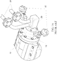
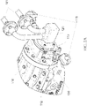
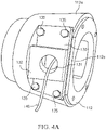
- FIGS. 1A-1 D An exemplary design according to the prior art is shown in FIGS. 1A-1 D .
- the prior art design includes a filler plate 12 arranged on one end of a bearing housing 10, with axial proximity probes 11, and an oil pump adapter 13.
- the filler plate 12 fills the void between the thrust bearing (not shown) and the oil pump adapter 13, and provides a structure to which the axial proximity probes 11 can be attached.
- Tilting pad thrust bearings require a well-controlled installation cavity depth from a tolerance standpoint.
- the manufacturing tolerances of all of the tilting pad bearing components are not held very close, so the overall length of the tilting pad bearing assembly can vary quite a bit.
- the bearing cavity 10b can be made extra deep, and a filler plate 12 is added to take up most of the extra space. Thin shims can be added between the filler plate 12 and the oil pump adapter 13 to control the bearing cavity 10b depth dimension adequately.
- the oil pump adapter 13 is secured to an auxiliary oil pump 20, which is configured to pump lubricating oil into the bearing housing 10 through piping 21.
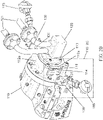
- the shaft 10a and the axial proximity probes 11 are arranged through the filler plate 12, and the axial proximity probes 11 include locking collars 11 a, such as hexagonal nuts, that are used to set the axial proximity probes 11 and lock them in place relative to the thrust collar (not shown) inside the bearing housing 10.
- Wiring (not shown) is attached to the axial proximity probes 11 outside the bearing housing 10, so that the axial proximity probes 11 can be connected to a monitoring system which can be configured to display information regarding the axial position of the thrust collar or provide an alert if an excessive axial position change has occurred in the bearing housing 10.
- An opening 14 is provided in the oil pump adapter 13 that is configured to receive an end of a probe wiring housing 15. The probe wiring can be passed through the opening 14 and through the probe wiring housing 15, and exit through an opening (not shown) at the opposite end of the probe wiring housing 15.
- the pump is warmed up with the bearing housing 10, oil pump adapter 13, probe wiring housings 15, auxiliary oil pump 20 and oil piping 21 fully assembled, as shown for example in FIG. 1A .
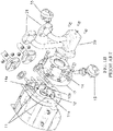
- the axial proximity probes 11 cannot be accessed by a pump operator.
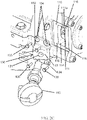
- the lube oil piping 21, the auxiliary oil pump 20, the proximity probe wiring connection housings 15 and the oil pump adapter 13 must be removed from the machine, as shown for example in FIG. 1B .
- the filler plate 12 is loose allowing for the final set point of the axial proximity probes 11 to be inaccurate. This procedure of disassembling and reassembling the pump in order to set the axial proximity probes 11 is also time consuming. It is an object of the present invention to address these shortcomings in the art.
- US 4 164 864 A discloses a compressor arrangement with apparatus similar to the invention.
- the present invention addresses these shortcomings of the art by providing a design that integrates the filler plate and a portion of the oil pump adapter into one piece.
- This new design has openings on each side that allow for access to the axial proximity probes by removing only the proximity probe connection housings and the proximity probe access plates.
- This design approach makes field setting axial proximity probes safer, faster, and more accurate than the previous design. Safety is improved by eliminating spilled oil encountered when disconnecting the piping.
- This design also allows for faster field setting because fewer components have to be disassembled from the machine to obtain access to the axial proximity probes.
- the field setting operation is more accurate with this design due to the fact that the axial proximity probes can be accessed quicker, and set when the machine is at a temperature closer to that of the warm up run.
- an apparatus is provided according to claim 1.
- the at least one removable access plate comprises an opening formed therethrough configured to receive a wiring housing and the wiring housing is configured to receive wiring connected to an axial proximity probe of the one or more axial proximity probes.
- the at least one removable access plate comprises a mounting block and the opening is formed through the mounting block; and the wiring housing is configured to be mounted in the mounting block.
- the mounting block of the at least one removable access plate comprises a sloped surface, and the opening through the mounting block and the at least one removable access plate is formed at a non-perpendicular angle relative to the at least one removable access plate.
- the apparatus further comprises a first plurality of openings positioned around the at least one access window, a second plurality of openings formed through the at least one access plate configured to align with the first plurality of openings when the at least one access plate covers the at least one access window, and a plurality of bolts configured to be inserted through the first and second plurality of openings to secure the at least one access plate to the at least one access window and configured to be removable to remove the at least one access plate from the at least one access window.
- the plurality of bolts and at least the first plurality of openings can be threaded.
- the apparatus comprises at least two access windows and at least two removable access plates.
- a second end of the apparatus is configured to be attached to an oil pump adapter configured to be connected to an auxiliary oil pump.
- the locking collar of the one or more axial proximity probes is configured to permit adjustment of an axial position of the one or more axial proximity probes.
- an apparatus is provided according to claim 8.
- the apparatus further comprises one or more wires, each configured to connect the one or more axial proximity probes to a pump monitoring system.
- the apparatus further comprises one or more wiring housings configured to receive the one or more wires.
- the at least one removable access plate of the adapter comprises an opening formed therethrough to receive a wiring housing of the one or more wiring housings.
- the at least one removable access plate comprises a mounting block and the opening is formed through the mounting block; and the wiring housing is configured to be mounted in the mounting block.
- the mounting block of the at least one removable access plate comprises a sloped surface, and the opening through the mounting block and the at least one removable access plate is formed at a perpendicular angle relative to the sloped surface of the at least one removable access plate so that the wiring housing is mounted in the mounting block perpendicular to the sloped surface of the at least one removable access plate.
- the adapter further comprises a first plurality of openings positioned around the at least one access window, a second plurality of openings formed through the at least one access plate configured to align with the first plurality of openings when the at least one access plate covers the at least one access window, and a plurality of bolts configured to be inserted through the first and second plurality of openings to secure the at least one access plate to the at least one access window and configured to be removable to remove the at least one access plate from the at least one access window.
- the plurality of bolts and at least the first plurality of openings can be threaded.
- the adapter comprises at least two access windows and at least two removable access plates.
- the apparatus further comprises an auxiliary oil pump attached to the adapter by an oil pump adapter and configured to pump lubricating oil to the pump bearing housing.
- the locking collar of the one or more axial proximity probes each is configured to permit adjustment of an axial position of the one or more axial proximity probes.
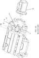
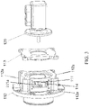
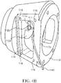
- FIGS. 2A-4C The present invention will now be described with reference made to FIGS. 2A-4C .
- an apparatus 112 namely a filler plate adapter 112 is provided for use with a bearing housing 110 of a pump that is configured to provide improved access to axial proximity probes 111 on a filler plate adapter 112 affixed to the bearing housing 110.
- the filler plate adapter 112 includes a plurality of side walls 112a configured to surround the axial proximity probes 111.
- the axial proximity probes 111 are attached to mounting tabs 112c within the filler plate adapter 112 to form a single apparatus comprising the filler plate adapter 112 and the axial proximity probes 111.
- the axial proximity probes 111 may be attached to the bearing housing 110 separately from the filler plate adapter 112.
- the filler plate adapter 112 is configured on one end to be attached to the bearing housing 110.
- the filler plate adapter 112 comprises a series of bolts around the perimeter of the filler plate adapter 112 that are received in corresponding openings through the bearing housing 110 to secure the filler plate adapter 112 to the bearing housing 110.
- the filler plate adapter 112 may be used in combination with an oil pump adapter 113 that is configured on another end to be attached to an auxiliary oil pump 120 connected to piping 121 supplying a lubricating oil to the bearing housing 110.
- the filler plate adapter 112 may be configured for use with other devices attached to the end of the bearing housing 110.
- the filler plate adapter 112 comprises one or more access windows 114 formed in one or more side walls 112a of the filler plate adapter 112, which are open so as to provide access to the axial proximity probes 111 within the walls 112a of the filler plate adapter 112.
- the access windows 114 are dimensioned to allow a pump operator to insert a wrench 150 or other tool through the access window 114 and adjust or set the axial proximity probes 111 by turning the locking collars 111a of the axial proximity probes 111, which may be hexagonal nuts or other shaped-nuts.
- Multiple access windows 114 may be provided on the filler plate adapter 112 to access multiple axial proximity probes 111. For example, in the embodiments shown in FIGS.
- two axial proximity probes 111 are included and two access windows 114 are provided on the filler plate adapter 112.
- only one axial proximity probe 111 may be used for the bearing housing 110, and the filler plate adapter 112 may comprise only one access window 114 or may comprise two or more access windows 114 to provide access to the axial proximity probe 111 from two or more sides 112a of the filler plate adapter 112.
- the filler plate adapter 112 may comprise one or more mounting tabs 112c configured to receive and mount the axial proximity probes 111.
- the mounting tab 112c can be arranged on the interior of a wall 112a of the filler plate adapter 112 and adjacent to the access windows 114.
- the mounting tab 112c comprises an opening (not shown) through the tab 112c that is configured to receive an axial proximity probe 111.
- a single mounting tab 112c can be utilized for mounting an axial proximity probe 111, and the number of mounting tabs 112c in the filler plate adapter 112 may vary depending on the number of axial proximity probes 111.
- the filler plate adapter 112 may also comprise a plate 112b to fills the void between the thrust bearing (not shown) and the interior of the filler plate adapter 112.
- the one or more axial proximity probes 111 can be attached to the plate 112b.
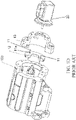
- One or more axial proximity probe access plates 130 are provided to cover the access windows 114 during operation of the pump, when the operator does not need to adjust or access the axial proximity probes 111.
- the access plates 130 are dimensioned so as to cover the access window 114.
- An opening 131 is provided through each access plate 130, which is configured to receive an end portion of a probe wiring housing 115.
- Wiring 140 connected to each axial proximity probe 111 is configured to pass through the opening 131 and through the probe wiring housing 115, and the wiring 140 can pass through an open end (not shown) of the probe wiring housing 115 for connection to a pump monitoring system.
- the opening 131 may pass through a mounting block 132 on the access plate 130.
- the probe wiring housing 115 is configured to be mounted in the mounting block 132 of the access plate 130.
- the mounting block 132 may include a sloped surface 133 that is configured to orient the probe wiring housing 115 at an angle away from the bearing housing 110.
- the opening 131 may be formed through the mounting block 132 at an angle that is non-perpendicular relative to the base of the access plate 130 attached to filler plate adapter 112 but perpendicular to the sloped surface 133.
- the access plates 130 may be provided without a mounting block 132 or a sloped surface 133 without departing from the scope of the invention.
- the access plate 130 can be attached and detached from the filler plate adapter 112 as needed.
- the access plate 130 comprises a plurality of openings 134 configured to receive a plurality of bolts or screws 135.
- a plurality of openings 116 are provided around the access window 114 in corresponding locations, so that when the access plate 130 is positioned over the access window 114, the openings 134 of the access plate 130 overlap with the openings 116 around the access window 114 and the bolts or screws 135 can be inserted through the overlapping openings 134 and 116.
- the bolts or screws 135 and one or both of the openings 134 and openings 116 may be threaded so that the access plate 130 can be securely fastened to filler plate adapter 112.
- the access plate 130 can be attached to the filler plate adapter 112 to cover the access window 114 using alternative means, such as magnetically attaching the access plate 130 to the filler plate adapter 112, providing one or more slots around the access window 114 that the access plate 130 can slide into, or providing latches or other locking members around the access window 114 that can latch or lock the access plate 130 over the access window 114.
- the access plate 130 can be removed from the filler plate adapter 112 by removing the bolts or screws 135, and the operator can access and adjust the locking collar 111a of the axial proximity probe 111.
- the operator does not need to detach the filler plate adapter 112 from the bearing housing 110 and does not need to detach the auxiliary oil pump 120 or piping 121 in order to set the axial proximity probes 111.
Landscapes
- Engineering & Computer Science (AREA)
- General Engineering & Computer Science (AREA)
- Mechanical Engineering (AREA)
- Physics & Mathematics (AREA)
- Fluid Mechanics (AREA)
- General Physics & Mathematics (AREA)
- Structures Of Non-Positive Displacement Pumps (AREA)
Claims (15)
- Vorrichtung (112), umfassend:eine Vielzahl von Seitenwänden (112a), wobei die Vielzahl von Seitenwänden an einem Ende so konfiguriert sind, dass sie an einem Pumpenlagergehäuse angebracht werden, und so konfiguriert sind, dass sie eine oder mehrere axiale Näherungssonden (111) umgeben, die konfiguriert sind, eine axiale Position eines oder mehrerer Druckringe in einem Pumpenlagergehäuse zu messen;mindestens ein Zugangsfenster (114), das durch mindestens eine Seitenwand der Vorrichtung hindurch gebildet ist, wobei das mindestens eine Zugangsfenster eine im Wesentlichen rechteckige Form aufweist und konfiguriert ist, einen Zugang zu einem Schlüssel zum Drehen eines Sperrrings (111a) der einen oder der mehreren axialen Näherungssonden bereitzustellen;mindestens eine entfernbare Zugangsplatte (130), die so konfiguriert ist, dass sie das mindestens eine Zugangsfenster zumindest teilweise bedeckt; undwobei die Vorrichtung ferner eine oder mehrere Befestigungslaschen umfasst, wobei die eine oder die mehreren axialen Näherungssonden in der einen oder den mehreren Befestigungslaschen der Vorrichtung angebracht sind.
- Vorrichtung (112) nach Anspruch 1, wobei die mindestens eine entfernbare Zugangsplatte eine durch sie hindurch gebildete Öffnung umfasst, die konfiguriert ist, ein Verdrahtungsgehäuse aufzunehmen, wobei das Verdrahtungsgehäuse konfiguriert ist, eine Verdrahtung aufzunehmen, die mit einer axialen Näherungssonde der einen oder der mehreren axialen Näherungssonden verbunden ist.
- Vorrichtung (112) nach Anspruch 2, wobei die mindestens eine entfernbare Zugangsplatte einen Anbringungsblock umfasst und die Öffnung durch den Anbringungsblock hindurch gebildet ist; und
wobei das Verdrahtungsgehäuse konfiguriert ist, in dem Anbringungsblock angebracht zu werden, und wobei der Anbringungsblock der mindestens einen entfernbaren Zugangsplatte optional eine geneigte Fläche umfasst, und wobei die Öffnung durch den Anbringungsblock und die mindestens eine entfernbare Zugangsplatte hindurch in einem senkrechten Winkel in Bezug auf die geneigte Fläche der mindestens einen entfernbaren Zugangsplatte gebildet ist. - Vorrichtung (112) nach Anspruch 1, ferner umfassend:eine erste Vielzahl von Öffnungen, die um das mindestens eine Zugangsfenster herum positioniert sind,eine zweite Vielzahl von Öffnungen, die durch die mindestens eine Zugangsplatte hindurch gebildet sind, die so konfiguriert sind, dass sie mit der ersten Vielzahl von Öffnungen ausgerichtet sind, wenn die mindestens eine Zugangsplatte das mindestens eine Zugangsfenster bedeckt, undeine Vielzahl von Bolzen, die konfiguriert sind, durch die erste und die zweite Vielzahl von Öffnungen hindurch eingesetzt zu werden, um die mindestens eine Zugangsplatte an dem mindestens einen Zugangsfenster zu befestigen, und so konfiguriert sind, dass sie entfernbar sind, um die mindestens eine Zugangsplatte von dem mindestens einen Zugangsfenster zu entfernen;wobei die Vielzahl von Bolzen und zumindest die erste Vielzahl von Öffnungen mit einem Gewinde versehen sind.
- Vorrichtung (112) nach Anspruch 1, wobei die Vorrichtung mindestens zwei Zugangsfenster und mindestens zwei entfernbare Zugangsplatten umfasst.
- Vorrichtung (112) nach Anspruch 1, wobei ein zweites Ende der Vorrichtung konfiguriert ist, an einem Ölpumpenadapter angebracht zu werden, welcher konfiguriert ist, mit einer Hilfsölpumpe verbunden zu werden.
- Vorrichtung (112) nach Anspruch 1, wobei der Sperrring der einen oder mehreren axialen Näherungssonden konfiguriert ist, eine Anpassung einer axialen Position der einen oder mehreren axialen Näherungssonden zu ermöglichen.
- Vorrichtung, umfassend:ein Pumpenlagergehäuse (110), das eine Pumpenwelle und einen oder mehrere Druckringe um die Pumpenwelle herum umfasst;eine oder mehrere axiale Näherungssonden (111), die konfiguriert sind, eine axiale Position des einen oder der mehreren Druckringe zu messen; undeinen Adapter (112), der Folgendes umfasst:eine Vielzahl von Seitenwänden (112a), wobei die Vielzahl von Seitenwänden an einem Ende so konfiguriert sind, dass sie an einem Pumpenlagergehäuse angebracht werden, und dass sie die eine oder die mehreren axialen Näherungssonden umgeben;mindestens ein Zugangsfenster (114), das durch mindestens eine Seitenwand des Adapters hindurch gebildet ist, wobei das mindestens eine Zugangsfenster eine im Wesentlichen rechteckige Form aufweist und konfiguriert ist, einen Zugang zu einem Schlüssel zum Drehen eines Sperrrings (111a) der einen oder der mehreren axialen Näherungssonden bereitzustellen;mindestens eine entfernbare Zugangsplatte (130), die so konfiguriert ist, dass sie das mindestens eine Zugangsfenster zumindest teilweise bedeckt; undwobei die Vorrichtung ferner eine oder mehrere Befestigungslaschen umfasst, wobei die eine oder die mehreren axialen Näherungssonden in der einen oder den mehreren Befestigungslaschen der Vorrichtung angebracht sind.
- Vorrichtung nach Anspruch 8, die ferner einen oder mehrere Drähte umfasst, die jeweils konfiguriert sind, die eine oder die mehreren axialen Näherungssonden mit einem Pumpenüberwachungssystem zu verbinden, und die optional ferner ein oder mehrere Verdrahtungsgehäuse umfasst, die konfiguriert sind, den einen oder die mehreren Drähte aufzunehmen.
- Vorrichtung nach Anspruch 9, wobei die mindestens eine entfernbare Zugangsplatte des Adapters eine durch sie hindurch gebildete Öffnung umfasst, die konfiguriert ist, ein Verdrahtungsgehäuse des einen oder der mehreren Verdrahtungsgehäuse aufzunehmen.
- Vorrichtung nach Anspruch 9, wobei die mindestens eine entfernbare Zugangsplatte einen Anbringungsblock umfasst und die Öffnung durch den Anbringungsblock hindurch gebildet ist; und
wobei das Verdrahtungsgehäuse konfiguriert ist, in dem Anbringungsblock angebracht zu werden, und wobei der Anbringungsblock der mindestens einen entfernbaren Zugangsplatte optional eine geneigte Fläche umfasst, und wobei die Öffnung durch den Anbringungsblock und die mindestens eine entfernbare Zugangsplatte hindurch in einem senkrechten Winkel in Bezug auf die geneigte Fläche der mindestens einen entfernbaren Zugangsplatte gebildet ist, sodass das Verdrahtungsgehäuse in dem Anbringungsblock senkrecht zu der geneigten Fläche der mindestens einen entfernbaren Zugangsplatte angebracht ist. - Vorrichtung nach Anspruch 8, wobei der Adapter ferner Folgendes umfasst: eine erste Vielzahl von Öffnungen, die um das mindestens eine Zugangsfenster herum positioniert sind, eine zweite Vielzahl von Öffnungen, die durch die mindestens eine Zugangsplatte hindurch gebildet sind, die so konfiguriert sind, dass sie mit der ersten Vielzahl von Öffnungen ausgerichtet sind, wenn die mindestens eine Zugangsplatte das mindestens eine Zugangsfenster bedeckt, undeine Vielzahl von Bolzen, die konfiguriert sind, durch die erste und die zweite Vielzahl von Öffnungen hindurch eingesetzt zu werden, um die mindestens eine Zugangsplatte an dem mindestens einen Zugangsfenster zu befestigen, und so konfiguriert sind, dass sie entfernbar sind, um die mindestens eine Zugangsplatte von dem mindestens einen Zugangsfenster zu entfernen;wobei die Vielzahl von Bolzen und zumindest die erste Vielzahl von Öffnungen mit einem Gewinde versehen sind.
- Vorrichtung nach Anspruch 8, wobei der Adapter mindestens zwei Zugangsfenster und mindestens zwei entfernbare Zugangsplatten umfasst.
- Vorrichtung nach Anspruch 8, ferner umfassend:
eine Hilfsölpumpe, die über einen Ölpumpenadapter an dem Adapter angebracht ist und konfiguriert ist, ein Schmieröl zu dem Pumpenlagergehäuse zu pumpen. - Vorrichtung nach Anspruch 8, wobei der Sperrring der einen oder der mehreren axialen Näherungssonden jeweils konfiguriert ist, eine Anpassung einer axialen Position der einen oder mehreren axialen Näherungssonden zu ermöglichen.
Applications Claiming Priority (2)
| Application Number | Priority Date | Filing Date | Title |
|---|---|---|---|
| US15/847,035 US11339830B2 (en) | 2017-12-19 | 2017-12-19 | Bearing housing filler plate |
| PCT/US2018/066226 WO2019126164A1 (en) | 2017-12-19 | 2018-12-18 | Bearing housing filler plate |
Publications (2)
| Publication Number | Publication Date |
|---|---|
| EP3728883A1 EP3728883A1 (de) | 2020-10-28 |
| EP3728883B1 true EP3728883B1 (de) | 2022-09-14 |
Family
ID=65003593
Family Applications (1)
| Application Number | Title | Priority Date | Filing Date |
|---|---|---|---|
| EP18830694.8A Active EP3728883B1 (de) | 2017-12-19 | 2018-12-18 | Füllplatte eines lagergehäuses |
Country Status (4)
| Country | Link |
|---|---|
| US (1) | US11339830B2 (de) |
| EP (1) | EP3728883B1 (de) |
| CN (1) | CN111630287B (de) |
| WO (1) | WO2019126164A1 (de) |
Families Citing this family (1)
| Publication number | Priority date | Publication date | Assignee | Title |
|---|---|---|---|---|
| CN117189791B (zh) * | 2023-11-07 | 2024-01-23 | 成都中科翼能科技有限公司 | 一种带传感器的动力涡轮轴承机匣组件 |
Family Cites Families (30)
| Publication number | Priority date | Publication date | Assignee | Title |
|---|---|---|---|---|
| GB412073A (en) * | 1933-09-20 | 1934-06-21 | Ulrich Meininghaus | Improvements in or relating to turbines, centrifugal pumps, and the like |
| US2921298A (en) * | 1956-10-31 | 1960-01-12 | Gulf Oil Corp | Thrust-bearing wear measuring apparatus |
| US4018083A (en) * | 1975-08-22 | 1977-04-19 | General Electric Company | Vibration detection probe holder |
| US4164864A (en) * | 1978-07-31 | 1979-08-21 | Allis-Chalmers Corporation | Method and apparatus for supporting a sensor in a normally inacessible area of a machine |
| US4367652A (en) * | 1980-07-07 | 1983-01-11 | The Metropolitan Sanitary District Of Greater Chicago | Method and apparatus for monitoring wastewater |
| US4495810A (en) * | 1983-04-20 | 1985-01-29 | General Electric Company | Probe mounting system |
| FI71838C (fi) * | 1984-10-11 | 1987-02-09 | Valmet Oy | Maetstuts. |
| US4877381A (en) | 1988-05-12 | 1989-10-31 | Tecumseh Products Company | Compressor shaft collar through port for pressure equalization between fluid pockets |
| US6309174B1 (en) * | 1997-02-28 | 2001-10-30 | Fluid Equipment Development Company, Llc | Thrust bearing for multistage centrifugal pumps |
| DE19804768B4 (de) * | 1998-02-06 | 2006-08-24 | Pfeiffer Vacuum Gmbh | Rotorlagerung für eine Gasreibungspumpe |
| US6227061B1 (en) | 1999-08-11 | 2001-05-08 | General Electric Co. | Mounting block for a proximity probe used for measuring axial movement of a rotor |
| US6408705B1 (en) | 2000-11-28 | 2002-06-25 | General Electric Company | Mounting block for a proximity probe used for measuring axial movement of a rotor |
| JP3846624B2 (ja) * | 2001-10-16 | 2006-11-15 | 住友電装株式会社 | ジョイントコネクタ |
| US20030198128A1 (en) | 2002-04-19 | 2003-10-23 | Carlson Roger W. | Mixing system having non-contacting bearings |
| US20070003406A1 (en) * | 2003-02-28 | 2007-01-04 | Racer Donald W | Pump |
| US7028949B2 (en) * | 2004-06-03 | 2006-04-18 | The Boeing Company | Landing assist probe mounting system |
| EP1674835A1 (de) * | 2004-12-27 | 2006-06-28 | Siemens Aktiengesellschaft | Sondenhalterungssystem, Verfahren zum Befestigen eines Sondenhalterungssystems und Verfahren zum Justieren einer Sonde |
| CA2688768C (en) | 2008-12-17 | 2017-02-14 | Roper Pump Company | Pump having modular shaft bearings and seals |
| DE102010007706A1 (de) * | 2010-02-11 | 2011-08-11 | Schaeffler Technologies GmbH & Co. KG, 91074 | Lagerkombination zur radialen und axialen Abstützung insbesondere für ein Los- oder Zwischenrad in einem Getriebe |
| US8943912B1 (en) | 2010-05-03 | 2015-02-03 | Ken E. Singleton | Proximity probe mounting device |
| JP5410385B2 (ja) * | 2010-08-23 | 2014-02-05 | 日本フローサーブ株式会社 | スラスト力測定器及びこれを使用したスラスト力の測定方法 |
| US9010812B2 (en) * | 2012-03-07 | 2015-04-21 | Mettler-Toledo Autochem, Inc. | Reaction vessel probe adapter |
| CN104712720B (zh) * | 2013-12-12 | 2017-10-24 | 北京中清能发动机技术有限公司 | 一种曲柄圆滑块机构及一种柱塞泵 |
| US9671250B2 (en) | 2014-04-22 | 2017-06-06 | General Electric Company | Subsea sensor assemblies |
| US9778144B2 (en) | 2014-09-18 | 2017-10-03 | General Electric Company | Systems and methods for attaching a probe to a casing of a gas turbine engine |
| JP6353778B2 (ja) | 2014-12-11 | 2018-07-04 | 株式会社酉島製作所 | メカニカルシールの支持装置 |
| CN204479015U (zh) | 2015-04-13 | 2015-07-15 | 中国核动力研究设计院 | 一种全密封泵推力轴承磨损量的在线监测装置 |
| CN205119175U (zh) | 2015-05-08 | 2016-03-30 | 上海诺地乐通用设备制造有限公司 | 管道离心式排油烟风机 |
| US10107437B2 (en) | 2015-09-15 | 2018-10-23 | Mustang Sampling Llc | Tooling friendly adapter for insertion probe access |
| DE102017106089B4 (de) | 2016-04-11 | 2023-05-25 | Micromass Uk Limited | Sondenanorndungsverbindung |
-
2017
- 2017-12-19 US US15/847,035 patent/US11339830B2/en active Active
-
2018
- 2018-12-18 EP EP18830694.8A patent/EP3728883B1/de active Active
- 2018-12-18 WO PCT/US2018/066226 patent/WO2019126164A1/en not_active Ceased
- 2018-12-18 CN CN201880087053.8A patent/CN111630287B/zh active Active
Also Published As
| Publication number | Publication date |
|---|---|
| US20190186547A1 (en) | 2019-06-20 |
| WO2019126164A1 (en) | 2019-06-27 |
| US11339830B2 (en) | 2022-05-24 |
| CN111630287A (zh) | 2020-09-04 |
| CN111630287B (zh) | 2022-07-26 |
| EP3728883A1 (de) | 2020-10-28 |
Similar Documents
| Publication | Publication Date | Title |
|---|---|---|
| US7661328B2 (en) | Probe holder system, method for fixing a probe holder system and method for adjusting a probe | |
| EP2999894B1 (de) | Lagervorrichtung mit einem klemmring mit eingebettetem sensor | |
| RU2601779C2 (ru) | Сегмент кожуха паровой турбины, паротурбинное устройство и паротурбинная установка | |
| CN111902635B (zh) | 潜水电机 | |
| EP3728883B1 (de) | Füllplatte eines lagergehäuses | |
| BR112019018436A2 (pt) | arranjo giratório com um medidor de ângulo | |
| KR101761718B1 (ko) | 배관의 스프링계 행거용 디지털 지침 감시 장치 및 방법 | |
| CN100575711C (zh) | 真空泵装置 | |
| WO2012123108A2 (de) | Elektrischer steckbereich eines elektromotors | |
| GB2334827A (en) | Housing support suitable particularly for housing containing a device such as an electric motor | |
| US12424902B2 (en) | Geared motor, in particular of a geared motor series, having an adapter part | |
| KR20190107028A (ko) | 클램핑 슬리브 조립체를 포함하는 믹서 | |
| JP5410385B2 (ja) | スラスト力測定器及びこれを使用したスラスト力の測定方法 | |
| DE102020119590A1 (de) | Gehäuse für einen Elektromotor und elektrische Antriebseinheit | |
| JP2007532086A (ja) | 電動モータによって駆動される機器のための制動装置 | |
| AU2022427727A1 (en) | Configurable base plate system for industrial pumps | |
| CN210483697U (zh) | 滑轮组件及旋挖钻机 | |
| CN216312421U (zh) | 配电箱调节座 | |
| US3365912A (en) | Fluid coupling and mounting means therefor | |
| CN209256770U (zh) | 工装 | |
| KR102887733B1 (ko) | 펌프의 회전차 간극 조정구 및 이를 이용한 펌프 | |
| US11732793B2 (en) | Geared motor | |
| EP1298424A1 (de) | Differenzdruckwandler mit einem vereinfachten Aufbau | |
| CN219734003U (zh) | 组合式齿轮箱电机法兰和动力总成 | |
| EP3020975A1 (de) | Vakuumgerät |
Legal Events
| Date | Code | Title | Description |
|---|---|---|---|
| STAA | Information on the status of an ep patent application or granted ep patent |
Free format text: STATUS: UNKNOWN |
|
| STAA | Information on the status of an ep patent application or granted ep patent |
Free format text: STATUS: THE INTERNATIONAL PUBLICATION HAS BEEN MADE |
|
| PUAI | Public reference made under article 153(3) epc to a published international application that has entered the european phase |
Free format text: ORIGINAL CODE: 0009012 |
|
| STAA | Information on the status of an ep patent application or granted ep patent |
Free format text: STATUS: REQUEST FOR EXAMINATION WAS MADE |
|
| 17P | Request for examination filed |
Effective date: 20200716 |
|
| AK | Designated contracting states |
Kind code of ref document: A1 Designated state(s): AL AT BE BG CH CY CZ DE DK EE ES FI FR GB GR HR HU IE IS IT LI LT LU LV MC MK MT NL NO PL PT RO RS SE SI SK SM TR |
|
| AX | Request for extension of the european patent |
Extension state: BA ME |
|
| DAV | Request for validation of the european patent (deleted) | ||
| DAX | Request for extension of the european patent (deleted) | ||
| STAA | Information on the status of an ep patent application or granted ep patent |
Free format text: STATUS: EXAMINATION IS IN PROGRESS |
|
| 17Q | First examination report despatched |
Effective date: 20210712 |
|
| RIC1 | Information provided on ipc code assigned before grant |
Ipc: F16C 17/06 20060101ALI20220226BHEP Ipc: F04D 29/60 20060101ALI20220226BHEP Ipc: F04D 29/40 20060101ALI20220226BHEP Ipc: F04D 29/041 20060101ALI20220226BHEP Ipc: F04D 15/00 20060101ALI20220226BHEP Ipc: F16C 17/08 20060101ALI20220226BHEP Ipc: H02K 5/167 20060101ALI20220226BHEP Ipc: F16C 23/00 20060101ALI20220226BHEP Ipc: F04D 29/051 20060101ALI20220226BHEP Ipc: F16C 35/00 20060101AFI20220226BHEP |
|
| GRAP | Despatch of communication of intention to grant a patent |
Free format text: ORIGINAL CODE: EPIDOSNIGR1 |
|
| STAA | Information on the status of an ep patent application or granted ep patent |
Free format text: STATUS: GRANT OF PATENT IS INTENDED |
|
| GRAS | Grant fee paid |
Free format text: ORIGINAL CODE: EPIDOSNIGR3 |
|
| INTG | Intention to grant announced |
Effective date: 20220711 |
|
| GRAA | (expected) grant |
Free format text: ORIGINAL CODE: 0009210 |
|
| STAA | Information on the status of an ep patent application or granted ep patent |
Free format text: STATUS: THE PATENT HAS BEEN GRANTED |
|
| AK | Designated contracting states |
Kind code of ref document: B1 Designated state(s): AL AT BE BG CH CY CZ DE DK EE ES FI FR GB GR HR HU IE IS IT LI LT LU LV MC MK MT NL NO PL PT RO RS SE SI SK SM TR |
|
| REG | Reference to a national code |
Ref country code: GB Ref legal event code: FG4D |
|
| REG | Reference to a national code |
Ref country code: CH Ref legal event code: EP |
|
| REG | Reference to a national code |
Ref country code: DE Ref legal event code: R096 Ref document number: 602018040751 Country of ref document: DE |
|
| REG | Reference to a national code |
Ref country code: IE Ref legal event code: FG4D |
|
| REG | Reference to a national code |
Ref country code: AT Ref legal event code: REF Ref document number: 1518864 Country of ref document: AT Kind code of ref document: T Effective date: 20221015 |
|
| REG | Reference to a national code |
Ref country code: LT Ref legal event code: MG9D |
|
| REG | Reference to a national code |
Ref country code: NL Ref legal event code: MP Effective date: 20220914 |
|
| PG25 | Lapsed in a contracting state [announced via postgrant information from national office to epo] |
Ref country code: SE Free format text: LAPSE BECAUSE OF FAILURE TO SUBMIT A TRANSLATION OF THE DESCRIPTION OR TO PAY THE FEE WITHIN THE PRESCRIBED TIME-LIMIT Effective date: 20220914 Ref country code: RS Free format text: LAPSE BECAUSE OF FAILURE TO SUBMIT A TRANSLATION OF THE DESCRIPTION OR TO PAY THE FEE WITHIN THE PRESCRIBED TIME-LIMIT Effective date: 20220914 Ref country code: NO Free format text: LAPSE BECAUSE OF FAILURE TO SUBMIT A TRANSLATION OF THE DESCRIPTION OR TO PAY THE FEE WITHIN THE PRESCRIBED TIME-LIMIT Effective date: 20221214 Ref country code: LV Free format text: LAPSE BECAUSE OF FAILURE TO SUBMIT A TRANSLATION OF THE DESCRIPTION OR TO PAY THE FEE WITHIN THE PRESCRIBED TIME-LIMIT Effective date: 20220914 Ref country code: LT Free format text: LAPSE BECAUSE OF FAILURE TO SUBMIT A TRANSLATION OF THE DESCRIPTION OR TO PAY THE FEE WITHIN THE PRESCRIBED TIME-LIMIT Effective date: 20220914 Ref country code: FI Free format text: LAPSE BECAUSE OF FAILURE TO SUBMIT A TRANSLATION OF THE DESCRIPTION OR TO PAY THE FEE WITHIN THE PRESCRIBED TIME-LIMIT Effective date: 20220914 |
|
| REG | Reference to a national code |
Ref country code: AT Ref legal event code: MK05 Ref document number: 1518864 Country of ref document: AT Kind code of ref document: T Effective date: 20220914 |
|
| PG25 | Lapsed in a contracting state [announced via postgrant information from national office to epo] |
Ref country code: HR Free format text: LAPSE BECAUSE OF FAILURE TO SUBMIT A TRANSLATION OF THE DESCRIPTION OR TO PAY THE FEE WITHIN THE PRESCRIBED TIME-LIMIT Effective date: 20220914 Ref country code: GR Free format text: LAPSE BECAUSE OF FAILURE TO SUBMIT A TRANSLATION OF THE DESCRIPTION OR TO PAY THE FEE WITHIN THE PRESCRIBED TIME-LIMIT Effective date: 20221215 |
|
| PG25 | Lapsed in a contracting state [announced via postgrant information from national office to epo] |
Ref country code: SM Free format text: LAPSE BECAUSE OF FAILURE TO SUBMIT A TRANSLATION OF THE DESCRIPTION OR TO PAY THE FEE WITHIN THE PRESCRIBED TIME-LIMIT Effective date: 20220914 Ref country code: RO Free format text: LAPSE BECAUSE OF FAILURE TO SUBMIT A TRANSLATION OF THE DESCRIPTION OR TO PAY THE FEE WITHIN THE PRESCRIBED TIME-LIMIT Effective date: 20220914 Ref country code: PT Free format text: LAPSE BECAUSE OF FAILURE TO SUBMIT A TRANSLATION OF THE DESCRIPTION OR TO PAY THE FEE WITHIN THE PRESCRIBED TIME-LIMIT Effective date: 20230116 Ref country code: ES Free format text: LAPSE BECAUSE OF FAILURE TO SUBMIT A TRANSLATION OF THE DESCRIPTION OR TO PAY THE FEE WITHIN THE PRESCRIBED TIME-LIMIT Effective date: 20220914 Ref country code: CZ Free format text: LAPSE BECAUSE OF FAILURE TO SUBMIT A TRANSLATION OF THE DESCRIPTION OR TO PAY THE FEE WITHIN THE PRESCRIBED TIME-LIMIT Effective date: 20220914 Ref country code: AT Free format text: LAPSE BECAUSE OF FAILURE TO SUBMIT A TRANSLATION OF THE DESCRIPTION OR TO PAY THE FEE WITHIN THE PRESCRIBED TIME-LIMIT Effective date: 20220914 |
|
| PG25 | Lapsed in a contracting state [announced via postgrant information from national office to epo] |
Ref country code: SK Free format text: LAPSE BECAUSE OF FAILURE TO SUBMIT A TRANSLATION OF THE DESCRIPTION OR TO PAY THE FEE WITHIN THE PRESCRIBED TIME-LIMIT Effective date: 20220914 Ref country code: PL Free format text: LAPSE BECAUSE OF FAILURE TO SUBMIT A TRANSLATION OF THE DESCRIPTION OR TO PAY THE FEE WITHIN THE PRESCRIBED TIME-LIMIT Effective date: 20220914 Ref country code: IS Free format text: LAPSE BECAUSE OF FAILURE TO SUBMIT A TRANSLATION OF THE DESCRIPTION OR TO PAY THE FEE WITHIN THE PRESCRIBED TIME-LIMIT Effective date: 20230114 Ref country code: EE Free format text: LAPSE BECAUSE OF FAILURE TO SUBMIT A TRANSLATION OF THE DESCRIPTION OR TO PAY THE FEE WITHIN THE PRESCRIBED TIME-LIMIT Effective date: 20220914 |
|
| REG | Reference to a national code |
Ref country code: DE Ref legal event code: R097 Ref document number: 602018040751 Country of ref document: DE |
|
| PG25 | Lapsed in a contracting state [announced via postgrant information from national office to epo] |
Ref country code: NL Free format text: LAPSE BECAUSE OF FAILURE TO SUBMIT A TRANSLATION OF THE DESCRIPTION OR TO PAY THE FEE WITHIN THE PRESCRIBED TIME-LIMIT Effective date: 20220914 Ref country code: AL Free format text: LAPSE BECAUSE OF FAILURE TO SUBMIT A TRANSLATION OF THE DESCRIPTION OR TO PAY THE FEE WITHIN THE PRESCRIBED TIME-LIMIT Effective date: 20220914 |
|
| P01 | Opt-out of the competence of the unified patent court (upc) registered |
Effective date: 20230528 |
|
| PLBE | No opposition filed within time limit |
Free format text: ORIGINAL CODE: 0009261 |
|
| STAA | Information on the status of an ep patent application or granted ep patent |
Free format text: STATUS: NO OPPOSITION FILED WITHIN TIME LIMIT |
|
| PG25 | Lapsed in a contracting state [announced via postgrant information from national office to epo] |
Ref country code: DK Free format text: LAPSE BECAUSE OF FAILURE TO SUBMIT A TRANSLATION OF THE DESCRIPTION OR TO PAY THE FEE WITHIN THE PRESCRIBED TIME-LIMIT Effective date: 20220914 |
|
| REG | Reference to a national code |
Ref country code: CH Ref legal event code: PL |
|
| 26N | No opposition filed |
Effective date: 20230615 |
|
| REG | Reference to a national code |
Ref country code: BE Ref legal event code: MM Effective date: 20221231 |
|
| PG25 | Lapsed in a contracting state [announced via postgrant information from national office to epo] |
Ref country code: SI Free format text: LAPSE BECAUSE OF FAILURE TO SUBMIT A TRANSLATION OF THE DESCRIPTION OR TO PAY THE FEE WITHIN THE PRESCRIBED TIME-LIMIT Effective date: 20220914 Ref country code: LU Free format text: LAPSE BECAUSE OF NON-PAYMENT OF DUE FEES Effective date: 20221218 |
|
| PG25 | Lapsed in a contracting state [announced via postgrant information from national office to epo] |
Ref country code: LI Free format text: LAPSE BECAUSE OF NON-PAYMENT OF DUE FEES Effective date: 20221231 Ref country code: IE Free format text: LAPSE BECAUSE OF NON-PAYMENT OF DUE FEES Effective date: 20221218 Ref country code: CH Free format text: LAPSE BECAUSE OF NON-PAYMENT OF DUE FEES Effective date: 20221231 |
|
| PG25 | Lapsed in a contracting state [announced via postgrant information from national office to epo] |
Ref country code: BE Free format text: LAPSE BECAUSE OF NON-PAYMENT OF DUE FEES Effective date: 20221231 |
|
| PG25 | Lapsed in a contracting state [announced via postgrant information from national office to epo] |
Ref country code: CY Free format text: LAPSE BECAUSE OF FAILURE TO SUBMIT A TRANSLATION OF THE DESCRIPTION OR TO PAY THE FEE WITHIN THE PRESCRIBED TIME-LIMIT Effective date: 20220914 |
|
| PG25 | Lapsed in a contracting state [announced via postgrant information from national office to epo] |
Ref country code: MK Free format text: LAPSE BECAUSE OF FAILURE TO SUBMIT A TRANSLATION OF THE DESCRIPTION OR TO PAY THE FEE WITHIN THE PRESCRIBED TIME-LIMIT Effective date: 20220914 Ref country code: HU Free format text: LAPSE BECAUSE OF FAILURE TO SUBMIT A TRANSLATION OF THE DESCRIPTION OR TO PAY THE FEE WITHIN THE PRESCRIBED TIME-LIMIT; INVALID AB INITIO Effective date: 20181218 |
|
| PG25 | Lapsed in a contracting state [announced via postgrant information from national office to epo] |
Ref country code: MC Free format text: LAPSE BECAUSE OF FAILURE TO SUBMIT A TRANSLATION OF THE DESCRIPTION OR TO PAY THE FEE WITHIN THE PRESCRIBED TIME-LIMIT Effective date: 20220914 |
|
| PG25 | Lapsed in a contracting state [announced via postgrant information from national office to epo] |
Ref country code: TR Free format text: LAPSE BECAUSE OF FAILURE TO SUBMIT A TRANSLATION OF THE DESCRIPTION OR TO PAY THE FEE WITHIN THE PRESCRIBED TIME-LIMIT Effective date: 20220914 Ref country code: MC Free format text: LAPSE BECAUSE OF FAILURE TO SUBMIT A TRANSLATION OF THE DESCRIPTION OR TO PAY THE FEE WITHIN THE PRESCRIBED TIME-LIMIT Effective date: 20220914 |
|
| PG25 | Lapsed in a contracting state [announced via postgrant information from national office to epo] |
Ref country code: BG Free format text: LAPSE BECAUSE OF FAILURE TO SUBMIT A TRANSLATION OF THE DESCRIPTION OR TO PAY THE FEE WITHIN THE PRESCRIBED TIME-LIMIT Effective date: 20220914 |
|
| PG25 | Lapsed in a contracting state [announced via postgrant information from national office to epo] |
Ref country code: MT Free format text: LAPSE BECAUSE OF FAILURE TO SUBMIT A TRANSLATION OF THE DESCRIPTION OR TO PAY THE FEE WITHIN THE PRESCRIBED TIME-LIMIT Effective date: 20220914 |
|
| PGFP | Annual fee paid to national office [announced via postgrant information from national office to epo] |
Ref country code: DE Payment date: 20241121 Year of fee payment: 7 |
|
| PGFP | Annual fee paid to national office [announced via postgrant information from national office to epo] |
Ref country code: GB Payment date: 20241122 Year of fee payment: 7 |
|
| PGFP | Annual fee paid to national office [announced via postgrant information from national office to epo] |
Ref country code: FR Payment date: 20241121 Year of fee payment: 7 |
|
| PGFP | Annual fee paid to national office [announced via postgrant information from national office to epo] |
Ref country code: IT Payment date: 20241121 Year of fee payment: 7 |