EP3728037B1 - Tragende struktur zur montage auf einem gasgenerator - Google Patents
Tragende struktur zur montage auf einem gasgenerator Download PDFInfo
- Publication number
- EP3728037B1 EP3728037B1 EP18833966.7A EP18833966A EP3728037B1 EP 3728037 B1 EP3728037 B1 EP 3728037B1 EP 18833966 A EP18833966 A EP 18833966A EP 3728037 B1 EP3728037 B1 EP 3728037B1
- Authority
- EP
- European Patent Office
- Prior art keywords
- suspension
- load
- bearing structure
- longitudinal
- gas generator
- Prior art date
- Legal status (The legal status is an assumption and is not a legal conclusion. Google has not performed a legal analysis and makes no representation as to the accuracy of the status listed.)
- Active
Links
Images


Classifications
-
- B—PERFORMING OPERATIONS; TRANSPORTING
- B64—AIRCRAFT; AVIATION; COSMONAUTICS
- B64D—EQUIPMENT FOR FITTING IN OR TO AIRCRAFT; FLIGHT SUITS; PARACHUTES; ARRANGEMENT OR MOUNTING OF POWER PLANTS OR PROPULSION TRANSMISSIONS IN AIRCRAFT
- B64D27/00—Arrangement or mounting of power plants in aircraft; Aircraft characterised by the type or position of power plants
- B64D27/02—Aircraft characterised by the type or position of power plants
- B64D27/16—Aircraft characterised by the type or position of power plants of jet type
- B64D27/18—Aircraft characterised by the type or position of power plants of jet type within, or attached to, wings
-
- B—PERFORMING OPERATIONS; TRANSPORTING
- B64—AIRCRAFT; AVIATION; COSMONAUTICS
- B64D—EQUIPMENT FOR FITTING IN OR TO AIRCRAFT; FLIGHT SUITS; PARACHUTES; ARRANGEMENT OR MOUNTING OF POWER PLANTS OR PROPULSION TRANSMISSIONS IN AIRCRAFT
- B64D27/00—Arrangement or mounting of power plants in aircraft; Aircraft characterised by the type or position of power plants
- B64D27/40—Arrangements for mounting power plants in aircraft
- B64D27/404—Suspension arrangements specially adapted for supporting vertical loads
-
- B—PERFORMING OPERATIONS; TRANSPORTING
- B64—AIRCRAFT; AVIATION; COSMONAUTICS
- B64D—EQUIPMENT FOR FITTING IN OR TO AIRCRAFT; FLIGHT SUITS; PARACHUTES; ARRANGEMENT OR MOUNTING OF POWER PLANTS OR PROPULSION TRANSMISSIONS IN AIRCRAFT
- B64D29/00—Power-plant nacelles, fairings or cowlings
- B64D29/06—Attaching of nacelles, fairings or cowlings
-
- Y—GENERAL TAGGING OF NEW TECHNOLOGICAL DEVELOPMENTS; GENERAL TAGGING OF CROSS-SECTIONAL TECHNOLOGIES SPANNING OVER SEVERAL SECTIONS OF THE IPC; TECHNICAL SUBJECTS COVERED BY FORMER USPC CROSS-REFERENCE ART COLLECTIONS [XRACs] AND DIGESTS
- Y02—TECHNOLOGIES OR APPLICATIONS FOR MITIGATION OR ADAPTATION AGAINST CLIMATE CHANGE
- Y02T—CLIMATE CHANGE MITIGATION TECHNOLOGIES RELATED TO TRANSPORTATION
- Y02T50/00—Aeronautics or air transport
- Y02T50/40—Weight reduction
Definitions
- the present invention relates to the field of suspensions of propulsion units for aircraft, and more particularly to a supporting structure configured to be fixed on a gas generator (in English: "engine core”) of a dual-flow turbojet (in English: “turbofan”), in order to allow its connection to a receiving structure of the aircraft, which can also be called an aircraft structure, through a suspension.
- a gas generator in English: "engine core”
- a dual-flow turbojet in English: "turbofan”
- a turbofan engine is suspended from a receiving structure of the aircraft, for example a pylon fixed under the wing, through an upstream suspension attached to an intermediate casing secured to the fan casing and a downstream suspension attached to the turbine casing.
- a receiving structure of the aircraft for example a pylon fixed under the wing
- an upstream suspension attached to an intermediate casing secured to the fan casing and a downstream suspension attached to the turbine casing.
- a supporting structure according to claim 1 is provided. Preferred embodiments are described in the dependent claims.
- this supporting structure configured to be mounted on a gas generator of a dual-flow turbojet engine for an aircraft in order to connect the dual-flow turbojet engine to a suspension structure without passing through the fan casing while ensuring the absorption of bending moments in the longitudinal direction without a large mass penalty.
- this supporting structure which can in particular be formed in a single piece, can comprise two longitudinal beams and a transverse connection connecting them, which can for example comprise a hoop.
- Each of the two longitudinal beams can comprise at least one front mounting interface and one rear mounting interface, for mounting the supporting structure on the gas generator, and a lateral suspension point for transmitting longitudinal and vertical forces between the supporting structure and a suspension structure.
- the rear mounting interface may be capable of allowing at least longitudinal movement of the gas generator, and the transverse connection may comprise a central suspension point with an orifice configured to receive a suspension snout oriented in the longitudinal direction to transmit lateral and vertical forces between the supporting structure and the suspension structure.
- suspension point of the supporting structure it is meant for example a fastener capable of transmitting forces between the supporting structure and the structure suspension. Since each attachment transmits forces at a fairly specific point, it can also be called an attachment point.
- the distances between the center of gravity of the turbofan engine and the attachment points of each front mounting interface, as well as between this center of gravity and the central suspension point, can be minimized, thereby reducing the bending forces, which can be efficiently taken up by the two longitudinal beams without any great penalty in terms of mass.
- the longitudinal deflection permitted by the rear mounting interfaces which may in particular each comprise longitudinal guide means, makes it possible to accommodate the thermal expansion of the gas generator in operation.
- These longitudinal guide means may comprise a slide adapted to receive a slide mounted on a stud secured to a turbine casing of the gas generator, but it is also possible to reverse this arrangement, to integrate the slide into the rear mounting interface, and the slide onto the turbine casing of the gas generator.
- each front mounting interface may be capable of transmitting longitudinal and transverse forces, for example by combining at least one bolt to transmit tensile forces and a lug to transmit shear forces.
- a second aspect of the present disclosure relates to a structural assembly comprising this supporting structure and a suspension structure fixed to the supporting structure by the rear and central suspension points.
- the suspension structure may comprise two suspension triangles, each fixed to a corresponding rear suspension point, while, in order to transmit forces in a transverse plane, the suspension structure may comprise a suspension snout, received in the longitudinal direction in a receptacle. corresponding to the central suspension point.
- the central suspension point may comprise a ball joint, comprising a ball joint nut in which the orifice is formed, in order to accommodate angular displacements between the supporting structure and the suspension structure.
- the suspension structure may comprise a suspension pyramid, the suspension snout being located on a summit of the suspension pyramid.
- a third aspect of the present disclosure relates to an aircraft comprising at least one receiving structure, a bypass turbojet engine and the structural assembly connecting the bypass turbojet engine to the receiving structure.
- the bypass turbojet engine can thus be suspended, for example, from a receiving structure secured to the wing of the aircraft, although it is also conceivable to use the structural assembly to connect the turbojet engine to a receiving structure directly secured to the fuselage of the aircraft, in particular the rear fuselage.
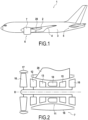
- FIG 1 illustrates an aircraft 1 comprising a fuselage 3, a wing 4 and a tail 5, and two propulsion units 6 suspended, under the wing 4, from corresponding receiving structures 2.
- Each receiving structure 2 may be integral with a respective wing among the two wings of the wing 4.
- the aircraft 1 can be substantially symmetrical with respect to a longitudinal and vertical plane, such that the other wing, with the respective receiving structure and propulsion unit 6, is located on the hidden side of the aircraft 1, and is therefore not visible in this figure.
- each receiving structure 2 can comprise a pylon fixed to the wing, for example by interfaces fixed on at least one spar of the wing.
- the receiving structure can also consist of a structural box of the wing.
- Another identical or similar propulsion unit 6 is also suspended from a second wing on the other side of the aircraft, not visible in the figure.
- Each of these two propulsion units 6 may comprise a dual-flow turbojet 7.
- this dual-flow turbojet 7 may comprise a fan 10 and a gas generator 11 formed by a low-pressure compressor 12, a high-pressure compressor 13, a combustion chamber 14, a high-pressure turbine 15 coupled to the high-pressure compressor 13 for its actuation, and a low-pressure turbine 16 coupled to the fan 10 and the low pressure compressor 12 for their actuation, aligned in the longitudinal direction along the longitudinal axis X which can also be the thrust axis of the dual-flow turbojet 7.
- the fan 10 and the gas generator 11 receive respective fairings 17, 18.
- the bypass turbojets 7 may have a high bypass ratio, for example greater than 5:1, 10:1, or even 15:1.
- the diameter of the fan 10 is therefore particularly large, such that, in order to maintain sufficient ground clearance, since the illustrated aircraft 1 has a low wing, the fan 10 is offset upwards and forwards relative to a conventional arrangement. To achieve this offset, the fan 10 is not suspended from the receiving structure 2 secured to the wing 4, but is held solely by its structural connections to the gas generator 11.
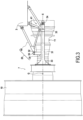
- the structural assembly 20 connecting each dual-flow turbojet 7 to the wing is not attached directly to the fan 10, but only to the gas generator 11, with the fan 10 thus suspended in cantilever relative to this assembly 20.
- this structural assembly 20 comprises a supporting structure 30 configured to be attached to the gas generator 11 and a suspension structure 40 for connecting the supporting structure 30 to the receiving structure of the aircraft 1.
- the supporting structure 30, which can in particular be formed in a single piece, comprises two longitudinal beams 31 and a transverse connection 32 connecting them rigidly.
- this transverse connection 32 is in the form of an arch, but other shapes can be envisaged for this transverse connection 32, such as for example a ring closed over 360°, single-body with the two longitudinal beams or attached to them, which could further reinforce the rigidity of the supporting structure 30 in the transverse plane.
- each of the two longitudinal beams 31 comprises at least one interface of front mounting 33 and a rear mounting interface 34, each interface configured to mount the structure to the gas generator 11, and a lateral suspension point 35 for connection with the suspension structure 40.
- These lateral suspension points 35 on the longitudinal beams 31 are complemented, as illustrated, by a central suspension point 36 for connection with the suspension structure 40, located on the transverse link 32.
- each front mounting interface 33 makes it possible to mount the supporting structure 30 on the gas generator 11.
- the gas generator of a dual-flow turbomachine is traversed by the primary flow vein of the turbomachine and is surrounded by the secondary flow vein of the turbomachine.
- Each front mounting interface 33 being fixed on the gas generator 11, it is located radially in an inter-vein space between the primary flow vein and the secondary flow vein.
- Each front mounting interface 33 may be configured to be fixed to a casing located upstream of the high-pressure compressor 13 of the gas generator 11, and axially downstream of a casing of the blower 10, for example a casing formed by an inter-compressor casing flange located between the low-pressure compressor 12 and the high-pressure compressor 13, and transmit forces both in the longitudinal direction and in a transverse plane perpendicular to the longitudinal axis X.
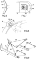
- each front mounting interface 33 may comprise a plate 331 with through holes 332 for receiving bolts to transmit longitudinal tensile forces, and at least one lug 333 for transmitting transverse shear forces. These transverse forces may be both lateral, i.e. parallel to the lateral axis Y, and vertical, i.e. parallel to the vertical axis Z.
- each rear mounting interface 34 may be configured to be connected to a housing closer to the rear end of the gas generator 11, for example a turbine housing, allowing relative longitudinal and transverse deflection of the gas generator 11 with respect to this rear mounting interface 34, so as to accommodate thermal expansion of the gas generator 11 in operation.
- each rear mounting interface 34 may comprise a slide 341 for receiving a slide 342 mounted on a stud 343 secured to the gas generator 11, for example a turbine casing of the gas generator 11, allowing a movement of the slide 342 in the longitudinal direction as well as in the lateral direction.
- the rear mounting interfaces 34 will normally only transmit vertical forces to compensate for the longitudinal offset between the center of gravity G of the dual-flow turbojet 7 and the front mounting interfaces 33.
- the supporting structure 30 when the supporting structure 30 is mounted on the gas generator 11, the latter can be fixed between the two longitudinal beams 31, oriented parallel to the longitudinal axis X of the dual-flow turbojet engine 7, so that they absorb the vertical bending moments, and in particular those generated by the overhang of the fan 10 (including the fan casing also designated by 10 on the figure 3 ), thus relieving the housings of the gas generator 11 of such forces.
- the lateral suspension points 35 may be located on the rear ends of the longitudinal beams 31, near the rear mounting interfaces 34, and be configured to transmit longitudinal and vertical forces.
- each lateral suspension point 35 may for example comprise an axis 351 intended to be received, oriented in the lateral direction, in a corresponding orifice in the suspension structure 40.
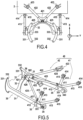
- the central suspension point 36 may be located, as illustrated, at the center of the transverse connection 32 straddling the gas generator 11 when the structure is mounted thereon. The central suspension point may then directly overhang the longitudinal axis X of the dual-flow turbojet 7, and be configured to transmit vertical and lateral forces in the transverse plane.
- the central suspension point 36 comprises, as illustrated, an orifice 361 configured to receive a suspension snout 362 oriented in the longitudinal direction.
- the central suspension point 36 may also comprise a ball joint 363 comprising a ball joint nut in which the orifice 361 is formed, in order to allow angular movement of the suspension snout 362 in the central suspension point 36, and thus avoid the transmission of moments through the central suspension point 36.
- the suspension structure 40 may comprise two suspension triangles 41, each configured to be connected by a lower tip 411 ( figure 5 ) to one of the lateral suspension points 35 of the structure 30.
- the lateral suspension points 35 comprise, as in the example illustrated, axles 351
- the yokes 412 intended to receive them can be formed in these lower points 411 of the suspension triangles 41.
- Each suspension triangle 41 can be oriented so as to transmit to the receiving structure 2 the vertical and longitudinal forces that it receives through the corresponding lateral suspension point 35.
- each suspension triangle 41 can be formed, as illustrated, by two connecting rods 413 connected by the lower point 411, although it is also possible to use a triangular plate 41' for each suspension triangle, as in the variant illustrated in the figure 9 .
- Each connecting rod 413 of each suspension triangle 41 may be configured, as illustrated, to be connected, by its end opposite the lower tip 411, to an attachment point 414 on the receiving structure 2, through an articulation 415 allowing at least one angular movement in the plane of the suspension triangle 41, so as to avoid the transmission of bending moments between the receiving structure 2 and each connecting rod 413.
- These articulations 415 may also comprise ball joints to allow angular movements in other planes.
- the suspension 40 may further comprise, as illustrated, a suspension pyramid 42 configured to connect the central suspension point 36 of the structure 30 to the receiving structure 2.
- this suspension pyramid 42 may comprise a top 421, in which the suspension snout 362 is formed, and four connecting rods joining at the top 421. More specifically, among these four connecting rods, two upper connecting rods 422 may be rigidly fixed to the top 421, extend towards corresponding attachment points 423 on the receiving structure 2, and be configured to be connected to these attachment points 423 through joints 424 to prevent the transmission of bending moments, in this inclined plane, between each of the attachment points 423 and the corresponding upper connecting rod 422.
- Two lower connecting rods 425 each connected by corresponding articulations 426, 427 to the apex 421 of the suspension pyramid 42 and to the lower point 411 of a respective suspension triangle 41, can complete the suspension pyramid 42 so as to maintain the gap between the apex 421 of the pyramid 42 and the lower points 411 of the suspension triangles 41.
- the geometry of the suspension structure 40 can thus be maintained even when the supporting structure 30 is detached therefrom.
- the two upper connecting rods 422 could also be replaced by a triangular plate 422', oriented in the inclined plane and connected in a similar manner to the top 421 of the suspension pyramid 42 and to the attachment points 423 on the receiving structure 2, as in the variant illustrated in the figure 9 , in which the elements equivalent to those of the figure 5 receive the same reference numbers.
- the aerodynamic impact of such a plate 422' on the airflow in the secondary flow vein of the dual-flow turbomachine can be controlled, for example by perforating the plate 422', which also makes it possible to reduce its mass.
- the triangular plates 41' and 422' replace each of the suspension triangles 41 as well as the upper connecting rods 422, it is also possible to replace only the upper connecting rods 422 or one and/or the other of the two suspension triangles 41 in a mixed suspension structure combining connecting rods and one or two triangular plates.
- the plate 422', or even one or the other of the plates 41' could be used as a support for a surface heat exchanger, for example an air/air or air/oil exchanger.
- each opening cover 50 may be located laterally relative to the gas generator 11 and be connected to the corresponding longitudinal beam 31 of the structure 30 by a mechanism of deployment 60.
- this deployment mechanism 60 may comprise a pivoting arm 61, extending between a first end 611 connected to the longitudinal beam 31 by a first hinge 612 whose pivot axis may in particular be vertical, and a second end 613 connected to the opening hood 50 by a second hinge 614, whose pivot axis may in particular be parallel to that of the first hinge 612.
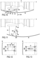
- this pivoting arm 61 may be formed, as illustrated, by two parallel connecting rods 615, 616, offset relative to each other along these pivot axes, as illustrated in the figure 12 .
- the pivot arm 61 is formed in one piece, with a certain width along the pivot axes, as in the variant illustrated in the figure 13 .
- the deployment mechanism 60 may further comprise a holding rod 62 extending between a first end 621, connected by a first articulation 622 to the pivoting arm 61 between its two ends 611, 613, and a second end 623, connected by a second articulation 624 to the opening hood 50.
- the first articulation 622 and/or the second articulation 624 of the holding rod 62 may be mounted on slides 625, as illustrated in the Figures 10 to 12 , and/or the holding rod 62 may be telescopic, as in the variant illustrated in the figure 14 .
- the deployment mechanism 60 may then also include a lock (not shown) for locking the holding rod 62 when the opening hood 50 is in the open position and/or in the closed position.
- the deployment mechanism 60 may also comprise, in addition to or as an alternative to the holding rod 62, a hood stay 63 capable of being releasably fixed between the longitudinal beam 31 and the opening hood 50 in the open position to maintain this open position, and/or at least one lock (not shown) for lock the opening hood 50 in the closed position by holding it for example by its upper and/or lower edge, as illustrated in the figures 12 And 14 .
- this seal 53 may comprise a rib 531 projecting radially inwards on the edge of the opening cover 50, and a groove 532 secured to the gas generator 11 and open radially outwards to receive the rib 531 when the opening cover 50 reaches the closed position.
- This arrangement may however also be reversed, so as to locate the rib on the gas generator 11 and the groove on the opening cover 50.
- the groove 532 may in particular have a V-shaped section.
- the deployment mechanism 60 may comprise at least two pivoting arms 61 parallel and offset relative to each other in the longitudinal direction, connected in a similar manner to the longitudinal beam 31 and to the opening hood 50, to thus form with them a deformable parallelogram making it possible to maintain the orientation of the opening hood 50 during its opening and closing.
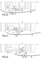
- the deployment mechanism 60 When opening the 50 opening hood from the closed position shown in the figure 10 with the deployment mechanism 60, it is first possible to pivot at least one pivoting arm 61, after unlocking the lock 64 and/or the holding rod 62, to laterally move the opening cover 50 away from the gas generator 11 while moving it downstream, and thus reach the open position illustrated in the figure 11 , in order to make the gas generator 11 accessible, for example for inspection, maintenance and/or repair work. Finally, the deployment mechanism 60 can be locked in this open position with the lock of the holding rod 62 and/or the hood stay 63 can be fixed between the longitudinal beam 31 and the opening hood 50 in order to prevent a closing untimely. These steps can then be reversed to close the opening hood 50, returning from the open position illustrated in the figure 11 to the closed position shown in the figure 10 .
- the deployment mechanism 60 may comprise, instead of one or more pivoting arms, one or more slides 65 secured to the longitudinal beam 31 and one or more sliders 66 secured to the opening hood 50 to allow opening and closing of the opening hood 50 by sliding the at least one slider 66 in the at least one slider 65.
- the slide 65 can be oriented in the longitudinal direction, thereby allowing longitudinal sliding of the opening hood 50 between its open position and its closed position.
- the deployment mechanism 60 may in particular comprise a first slide 65 located on an upper face of the longitudinal beam 31 and a second slide 65 located on a lower face of the longitudinal beam 31, each receiving at least two slides 66 connected to the opening cover 50 and mutually offset in the longitudinal direction.
- the slide 65 may include at least one lock 651 at the end of its travel. Furthermore, to facilitate their sliding, the slides 66 may be provided with rollers 661 capable of rolling on rolling surfaces 652 in the slide 65, as illustrated in FIG. figure 19 .
- the other elements illustrated being equivalent to those of the first example, they receive the same reference numbers on the Figures 17 to 19 than in the previous figures.
- each slider 66 can then be connected to the opening hood 50 by a pivoting arm 61 extending between a first end 611 connected to the slider 66 by a first hinge 612 whose pivot axis can in particular be vertical, and a second end 613 connected to the opening hood 50 by a second hinge 614, whose pivot axis can in particular be parallel to that of the first hinge 612.
- the slider 65 can comprise at least one lock 651 at the end of its travel, as in the second example mentioned above, and at least one of the hinges 612, 614 comprises a lock (not illustrated) for releasably locking the angular movement of the at least one pivoting arm 61.
- the other elements illustrated being equivalent to those of the first two examples, they receive the same reference numbers on the Figures 17 to 19 than in the previous figures.
Landscapes
- Engineering & Computer Science (AREA)
- Aviation & Aerospace Engineering (AREA)
- Structures Of Non-Positive Displacement Pumps (AREA)
- Turbine Rotor Nozzle Sealing (AREA)
Claims (12)
- Tragende Struktur (30), die derart ausgelegt ist, dass sie an einem Gasgenerator (11) eines Mantelstromtriebwerks (7) für ein Luftfahrzeug anbringbar ist, wobei die tragende Struktur (30) umfasst:zwei Längsträger (31), die jeweils umfassen:eine vordere Montageschnittstelle (33) und eine hintere Montageschnittstelle (34), um die tragende Struktur (30) an dem Gasgenerator (11) anzubringen, wobei die hintere Montageschnittstelle (34) imstande ist, mindestens eine Längsauslenkung des Gasgenerators (11) zu gestatten, undeinen seitlichen Aufhängungspunkt (35), um Längs- und Vertikalkräfte zwischen der tragenden Struktur (30) und einer Aufhängungsstruktur (40) zu übertragen, undeine Querverbindung (32), die die beiden Längsträger (31) verbindet,wobei die tragende Struktur dadurch gekennzeichnet ist, dass die Querverbindung (32) einen zentralen Aufhängungspunkt (36) mit einer Öffnung (361) umfasst, die ausgelegt ist, um eine Aufhängungsnase (362) aufzunehmen, die in Längsrichtung ausgerichtet ist, um seitliche und vertikale Kräfte zwischen der tragenden Struktur (30) und der Aufhängungsstruktur (40) zu übertragen.
- Tragende Struktur (30) nach Anspruch 1, wobei die hinteren Montageschnittstellen (34) ebenfalls imstande sind, seitliche Auslenkungen des Gasgenerators (11) zu gestatten.
- Tragende Struktur (30) nach einem der Ansprüche 1 oder 2, wobei jede hintere Montageschnittstelle (34) Mittel zur Längsführung umfasst.
- Tragende Struktur nach Anspruch 3, wobei die Mittel zur Längsführung jeder hinteren Montageschnittstelle eine Gleitschiene (341) umfassen, die imstande ist, ein Gleitstück (342) aufzunehmen, das auf einem Klotz (343) angebracht ist, der fest mit einem Turbinengehäuse des Gasgenerators (11) verbunden ist.
- Tragende Struktur (30) nach einem der vorhergehenden Ansprüche, wobei jede vordere Montageschnittstelle (33) imstande ist, Längs- und Transversalkräfte zu übertragen.
- Tragende Struktur (30) nach einem der vorhergehenden Ansprüche, die aus einem einzigen einteiligen Stück gebildet ist.
- Tragende Struktur (30) nach einem der vorhergehenden Ansprüche, wobei die Querverbindung (32), die die beiden Längsträger (31) verbindet, einen Bügel umfasst.
- Strukturanordnung (20), die die tragende Struktur (30) nach einem der vorhergehenden Ansprüche und eine Aufhängungsstruktur (40) umfasst, die an der tragenden Struktur (30) durch die seitlichen und zentralen Aufhängungspunkte (35, 36) befestigt ist.
- Strukturanordnung (20) nach Anspruch 8, wobei die Aufhängungsstruktur (40) zwei Aufhängungsdreiecke (41) umfasst, die jeweils an einem der entsprechenden seitlichen Aufhängungspunkte (35) befestigt sind.
- Strukturanordnung (20) nach einem der Ansprüche 8 oder 9, wobei die Aufhängungsstruktur (40) die Aufhängungsnase (362) umfasst, die in Längsrichtung in der entsprechenden Öffnung (361) des zentralen Aufhängungspunktes (36) aufgenommen wird, wobei der zentrale Aufhängungspunkt ebenfalls ein Kugelgelenk (363) umfasst, das eine Kugelgelenknuss aufweist, in der die Öffnung (361) ausgebildet ist.
- Strukturanordnung (20) nach Anspruch 10, wobei die Aufhängungsstruktur (30) eine Aufhängungspyramide (42) umfasst, wobei die Aufhängungsnase an einem Scheitelpunkt (421) der Aufhängungspyramide (42) angeordnet ist.
- Luftfahrzeug (1), umfassend mindestens eine Empfangsstruktur (2), ein Mantelstromtriebwerk (7) und die Strukturanordnung (20) nach einem der Ansprüche 8 bis 11, die das Mantelstromtriebwerk (7) mit der Empfangsstruktur (2) verbindet.
Applications Claiming Priority (2)
| Application Number | Priority Date | Filing Date | Title |
|---|---|---|---|
| FR1762324A FR3075174B1 (fr) | 2017-12-18 | 2017-12-18 | Structure porteuse destinee au montage sur un generateur de gaz |
| PCT/FR2018/053364 WO2019122680A1 (fr) | 2017-12-18 | 2018-12-18 | Structure porteuse destinée au montage sur un générateur de gaz |
Publications (2)
| Publication Number | Publication Date |
|---|---|
| EP3728037A1 EP3728037A1 (de) | 2020-10-28 |
| EP3728037B1 true EP3728037B1 (de) | 2025-03-05 |
Family
ID=61750322
Family Applications (1)
| Application Number | Title | Priority Date | Filing Date |
|---|---|---|---|
| EP18833966.7A Active EP3728037B1 (de) | 2017-12-18 | 2018-12-18 | Tragende struktur zur montage auf einem gasgenerator |
Country Status (5)
| Country | Link |
|---|---|
| US (1) | US11542024B2 (de) |
| EP (1) | EP3728037B1 (de) |
| CN (1) | CN111556843B (de) |
| FR (1) | FR3075174B1 (de) |
| WO (1) | WO2019122680A1 (de) |
Families Citing this family (2)
| Publication number | Priority date | Publication date | Assignee | Title |
|---|---|---|---|---|
| FR3089248B1 (fr) * | 2018-12-03 | 2020-11-20 | Safran Aircraft Engines | Ensemble moteur pour aéronef présentant un support de système d’échangeur air-huile a fixation optimisée |
| EP4488180A1 (de) * | 2023-07-06 | 2025-01-08 | Airbus Operations (S.A.S.) | Antriebssystem für ein flugzeug mit einem strahltriebwerk, einem pylon und einer motorbefestigung |
Citations (3)
| Publication number | Priority date | Publication date | Assignee | Title |
|---|---|---|---|---|
| FR2873985B1 (fr) * | 2004-08-04 | 2006-11-24 | Airbus France Sas | Ensemble moteur pour aeronef |
| FR2873988B1 (fr) * | 2004-08-05 | 2007-12-21 | Airbus France Sas | Mat d'accrochage de turboreacteur pour aeronef |
| EP2067698B1 (de) * | 2007-12-07 | 2011-06-15 | Snecma | Aufhängung eines Triebwerks an einem Luftschiff |
Family Cites Families (8)
| Publication number | Priority date | Publication date | Assignee | Title |
|---|---|---|---|---|
| FR2903076B1 (fr) | 2006-06-30 | 2009-05-29 | Aircelle Sa | Nacelle structurante |
| FR2948636B1 (fr) * | 2009-07-31 | 2012-01-13 | Airbus Operations Sas | Ensemble moteur pour aeronef dont le mat d'accrochage comprend une enveloppe structurale formant delimitation radiale interne du flux secondaire |
| FR2964364B1 (fr) * | 2010-09-03 | 2012-09-28 | Airbus Operations Sas | Mat d'accrochage de turboreacteur pour aeronef comprenant des attaches voilure avant alignees |
| FR2976914B1 (fr) * | 2011-06-23 | 2014-12-26 | Snecma | Structure d'accrochage d'une turbomachine |
| FR2981046B1 (fr) * | 2011-10-06 | 2013-10-25 | Aircelle Sa | Ensemble propulsif d'aeronef |
| FR2993535B1 (fr) * | 2012-07-20 | 2015-03-06 | Airbus Operations Sas | Ensemble propulsif comprenant un turboreacteur a double flux de tres grand diametre et son dispositif d'accrochage sous la voilure d'un aeronef |
| FR3015433B1 (fr) * | 2013-12-23 | 2016-02-12 | Airbus Operations Sas | Ensemble pour aeronef comprenant un mat d'accrochage integre a la nacelle et agence en partie arriere du fuselage |
| FR3026137B1 (fr) * | 2014-09-22 | 2019-03-15 | Safran Aircraft Engines | Element pour une turbomachine, telle par exemple qu'un turboreacteur ou un turbopropulseur d'avion |
-
2017
- 2017-12-18 FR FR1762324A patent/FR3075174B1/fr active Active
-
2018
- 2018-12-18 US US16/954,737 patent/US11542024B2/en active Active
- 2018-12-18 CN CN201880085531.1A patent/CN111556843B/zh active Active
- 2018-12-18 WO PCT/FR2018/053364 patent/WO2019122680A1/fr not_active Ceased
- 2018-12-18 EP EP18833966.7A patent/EP3728037B1/de active Active
Patent Citations (3)
| Publication number | Priority date | Publication date | Assignee | Title |
|---|---|---|---|---|
| FR2873985B1 (fr) * | 2004-08-04 | 2006-11-24 | Airbus France Sas | Ensemble moteur pour aeronef |
| FR2873988B1 (fr) * | 2004-08-05 | 2007-12-21 | Airbus France Sas | Mat d'accrochage de turboreacteur pour aeronef |
| EP2067698B1 (de) * | 2007-12-07 | 2011-06-15 | Snecma | Aufhängung eines Triebwerks an einem Luftschiff |
Also Published As
| Publication number | Publication date |
|---|---|
| EP3728037A1 (de) | 2020-10-28 |
| US20210086906A1 (en) | 2021-03-25 |
| FR3075174B1 (fr) | 2020-12-11 |
| US11542024B2 (en) | 2023-01-03 |
| FR3075174A1 (fr) | 2019-06-21 |
| WO2019122680A1 (fr) | 2019-06-27 |
| CN111556843A (zh) | 2020-08-18 |
| CN111556843B (zh) | 2024-05-07 |
Similar Documents
| Publication | Publication Date | Title |
|---|---|---|
| CA2541127C (fr) | Suspension arriere de turboreacteur | |
| EP2426051B1 (de) | Strahlturbinenpylon mit fluchtenden vorderen Befestigungspunkten | |
| EP2082960B1 (de) | Aufhängung eines Antriebssystems an einem Strukturelement eines Luftfahrzeugs | |
| EP2723642B1 (de) | Aufhängestruktur einer turbomaschine | |
| CA2602141C (fr) | Systeme propulsif integre comportant un moteur a turboreacteur a double flux | |
| EP3757012B1 (de) | Flugzeugantriebssystem mit verbesserter primärmaststruktur und vorderer triebwerksbefestigung | |
| EP2390187B1 (de) | Herstellungsverfahren für eine Rippe einer aerodynamischen Verkleidung eines Triebwerkspylons durch superplastische Verformung und Verlaschung | |
| EP3867503B1 (de) | Motoranordnung für ein flugzeug mit luftöltauscher-systemträger mit optimierter befestigung | |
| FR3061480A1 (fr) | Ensemble moteur pour aeronef comprenant une attache moteur avant facilitant son montage | |
| EP3505439B1 (de) | Einheit für ein luftfahrzeug, die eine primärstruktur eines aufhängungsmasts umfasst, die an einem flügelkasten durch befestigungselemente befestigt ist und im vorderkantenbereich ein reduziertes volumen aufweist | |
| EP2436601A1 (de) | Vorrichtung zur Aufnahme der Schubkräfte eines Triebwerks mit drei in Reihe angeordneten Kugelgelenken | |
| FR3040076A1 (fr) | Ensemble moteur pour aeronef comprenant une structure primaire de mat d'accrochage equipee d'une extension de caisson comprenant deux parties en forme globale d'arceau | |
| FR2965548A1 (fr) | Mat d'accrochage d'un moteur d'aeronef comprenant deux attaches voilure avant a pions de cisaillement orthogonaux | |
| EP1480876A1 (de) | Aufhängung eines triebwerks unter einer flugzeugtragfläche | |
| EP3505448B1 (de) | Einheit für ein luftfahrzeug, die eine primärstruktur eines aufhängungsmasts umfasst, die an einem flügelkasten mithilfe von anschlüssen reduzierten volumens in der vorderkantenzone befestigt ist | |
| FR3020343A1 (fr) | Ensemble pour aeronef comprenant une structure primaire de mat d'accrochage constituee par trois elements independants | |
| FR3032421A1 (fr) | Ensemble pour aeronef comprenant une structure primaire de mat d'accrochage integree a la structure de l'element de voilure | |
| FR2925016A1 (fr) | Suspension d'un turboreacteur a un aeronef | |
| EP3728041B1 (de) | Öffnende triebwerksverkleidungsanordnung und einsatzmechanismus | |
| FR3060531A1 (fr) | Partie arriere d'aeronef comprenant un cadre de fuselage supportant deux moteurs partiellement enterres | |
| FR2873985A1 (fr) | Ensemble moteur pour aeronef | |
| EP3728037B1 (de) | Tragende struktur zur montage auf einem gasgenerator | |
| EP4288652B1 (de) | Schubumkehrvorrichtung mit beweglichen gittern und durch aussparung montierten hauben | |
| FR3113484A1 (fr) | Ensemble propulseur d’aéronef comprenant des bielles d’une attache moteur avant reliées directement à un renfort transversal avant d’une structure primaire d’un mât d’aéronef | |
| EP4112477A1 (de) | Luftfahrzeug-triebwerkseinheit mit einer vorderen triebwerksaufhängung mit einem querträger, der teilweise gegenüber einer vorderen querverstärkung einer primärstruktur eines mastes positioniert ist |
Legal Events
| Date | Code | Title | Description |
|---|---|---|---|
| STAA | Information on the status of an ep patent application or granted ep patent |
Free format text: STATUS: UNKNOWN |
|
| STAA | Information on the status of an ep patent application or granted ep patent |
Free format text: STATUS: THE INTERNATIONAL PUBLICATION HAS BEEN MADE |
|
| PUAI | Public reference made under article 153(3) epc to a published international application that has entered the european phase |
Free format text: ORIGINAL CODE: 0009012 |
|
| STAA | Information on the status of an ep patent application or granted ep patent |
Free format text: STATUS: REQUEST FOR EXAMINATION WAS MADE |
|
| 17P | Request for examination filed |
Effective date: 20200616 |
|
| AK | Designated contracting states |
Kind code of ref document: A1 Designated state(s): AL AT BE BG CH CY CZ DE DK EE ES FI FR GB GR HR HU IE IS IT LI LT LU LV MC MK MT NL NO PL PT RO RS SE SI SK SM TR |
|
| AX | Request for extension of the european patent |
Extension state: BA ME |
|
| DAV | Request for validation of the european patent (deleted) | ||
| DAX | Request for extension of the european patent (deleted) | ||
| STAA | Information on the status of an ep patent application or granted ep patent |
Free format text: STATUS: EXAMINATION IS IN PROGRESS |
|
| 17Q | First examination report despatched |
Effective date: 20220419 |
|
| GRAP | Despatch of communication of intention to grant a patent |
Free format text: ORIGINAL CODE: EPIDOSNIGR1 |
|
| STAA | Information on the status of an ep patent application or granted ep patent |
Free format text: STATUS: GRANT OF PATENT IS INTENDED |
|
| RIC1 | Information provided on ipc code assigned before grant |
Ipc: B64D 27/40 20240101ALI20240916BHEP Ipc: B64D 29/06 20060101ALI20240916BHEP Ipc: B64D 27/18 20060101AFI20240916BHEP |
|
| INTG | Intention to grant announced |
Effective date: 20241023 |
|
| GRAS | Grant fee paid |
Free format text: ORIGINAL CODE: EPIDOSNIGR3 |
|
| GRAA | (expected) grant |
Free format text: ORIGINAL CODE: 0009210 |
|
| STAA | Information on the status of an ep patent application or granted ep patent |
Free format text: STATUS: THE PATENT HAS BEEN GRANTED |
|
| AK | Designated contracting states |
Kind code of ref document: B1 Designated state(s): AL AT BE BG CH CY CZ DE DK EE ES FI FR GB GR HR HU IE IS IT LI LT LU LV MC MK MT NL NO PL PT RO RS SE SI SK SM TR |
|
| REG | Reference to a national code |
Ref country code: GB Ref legal event code: FG4D Free format text: NOT ENGLISH |
|
| REG | Reference to a national code |
Ref country code: CH Ref legal event code: EP |
|
| REG | Reference to a national code |
Ref country code: IE Ref legal event code: FG4D Free format text: LANGUAGE OF EP DOCUMENT: FRENCH |
|
| REG | Reference to a national code |
Ref country code: DE Ref legal event code: R096 Ref document number: 602018079886 Country of ref document: DE |
|
| PG25 | Lapsed in a contracting state [announced via postgrant information from national office to epo] |
Ref country code: RS Free format text: LAPSE BECAUSE OF FAILURE TO SUBMIT A TRANSLATION OF THE DESCRIPTION OR TO PAY THE FEE WITHIN THE PRESCRIBED TIME-LIMIT Effective date: 20250605 |
|
| PG25 | Lapsed in a contracting state [announced via postgrant information from national office to epo] |
Ref country code: FI Free format text: LAPSE BECAUSE OF FAILURE TO SUBMIT A TRANSLATION OF THE DESCRIPTION OR TO PAY THE FEE WITHIN THE PRESCRIBED TIME-LIMIT Effective date: 20250305 |
|
| REG | Reference to a national code |
Ref country code: NL Ref legal event code: MP Effective date: 20250305 |
|
| PG25 | Lapsed in a contracting state [announced via postgrant information from national office to epo] |
Ref country code: ES Free format text: LAPSE BECAUSE OF FAILURE TO SUBMIT A TRANSLATION OF THE DESCRIPTION OR TO PAY THE FEE WITHIN THE PRESCRIBED TIME-LIMIT Effective date: 20250305 |
|
| REG | Reference to a national code |
Ref country code: LT Ref legal event code: MG9D |
|
| PG25 | Lapsed in a contracting state [announced via postgrant information from national office to epo] |
Ref country code: NO Free format text: LAPSE BECAUSE OF FAILURE TO SUBMIT A TRANSLATION OF THE DESCRIPTION OR TO PAY THE FEE WITHIN THE PRESCRIBED TIME-LIMIT Effective date: 20250605 |
|
| PG25 | Lapsed in a contracting state [announced via postgrant information from national office to epo] |
Ref country code: HR Free format text: LAPSE BECAUSE OF FAILURE TO SUBMIT A TRANSLATION OF THE DESCRIPTION OR TO PAY THE FEE WITHIN THE PRESCRIBED TIME-LIMIT Effective date: 20250305 |
|
| PG25 | Lapsed in a contracting state [announced via postgrant information from national office to epo] |
Ref country code: LV Free format text: LAPSE BECAUSE OF FAILURE TO SUBMIT A TRANSLATION OF THE DESCRIPTION OR TO PAY THE FEE WITHIN THE PRESCRIBED TIME-LIMIT Effective date: 20250305 |
|
| PG25 | Lapsed in a contracting state [announced via postgrant information from national office to epo] |
Ref country code: BG Free format text: LAPSE BECAUSE OF FAILURE TO SUBMIT A TRANSLATION OF THE DESCRIPTION OR TO PAY THE FEE WITHIN THE PRESCRIBED TIME-LIMIT Effective date: 20250305 Ref country code: GR Free format text: LAPSE BECAUSE OF FAILURE TO SUBMIT A TRANSLATION OF THE DESCRIPTION OR TO PAY THE FEE WITHIN THE PRESCRIBED TIME-LIMIT Effective date: 20250606 |
|
| REG | Reference to a national code |
Ref country code: AT Ref legal event code: MK05 Ref document number: 1772764 Country of ref document: AT Kind code of ref document: T Effective date: 20250305 |
|
| PG25 | Lapsed in a contracting state [announced via postgrant information from national office to epo] |
Ref country code: NL Free format text: LAPSE BECAUSE OF FAILURE TO SUBMIT A TRANSLATION OF THE DESCRIPTION OR TO PAY THE FEE WITHIN THE PRESCRIBED TIME-LIMIT Effective date: 20250305 |
|
| PG25 | Lapsed in a contracting state [announced via postgrant information from national office to epo] |
Ref country code: SE Free format text: LAPSE BECAUSE OF FAILURE TO SUBMIT A TRANSLATION OF THE DESCRIPTION OR TO PAY THE FEE WITHIN THE PRESCRIBED TIME-LIMIT Effective date: 20250305 |
|
| PG25 | Lapsed in a contracting state [announced via postgrant information from national office to epo] |
Ref country code: SM Free format text: LAPSE BECAUSE OF FAILURE TO SUBMIT A TRANSLATION OF THE DESCRIPTION OR TO PAY THE FEE WITHIN THE PRESCRIBED TIME-LIMIT Effective date: 20250305 |
|
| PG25 | Lapsed in a contracting state [announced via postgrant information from national office to epo] |
Ref country code: PT Free format text: LAPSE BECAUSE OF FAILURE TO SUBMIT A TRANSLATION OF THE DESCRIPTION OR TO PAY THE FEE WITHIN THE PRESCRIBED TIME-LIMIT Effective date: 20250707 |
|
| PG25 | Lapsed in a contracting state [announced via postgrant information from national office to epo] |
Ref country code: IT Free format text: LAPSE BECAUSE OF FAILURE TO SUBMIT A TRANSLATION OF THE DESCRIPTION OR TO PAY THE FEE WITHIN THE PRESCRIBED TIME-LIMIT Effective date: 20250305 Ref country code: PL Free format text: LAPSE BECAUSE OF FAILURE TO SUBMIT A TRANSLATION OF THE DESCRIPTION OR TO PAY THE FEE WITHIN THE PRESCRIBED TIME-LIMIT Effective date: 20250305 |
|
| PG25 | Lapsed in a contracting state [announced via postgrant information from national office to epo] |
Ref country code: AT Free format text: LAPSE BECAUSE OF FAILURE TO SUBMIT A TRANSLATION OF THE DESCRIPTION OR TO PAY THE FEE WITHIN THE PRESCRIBED TIME-LIMIT Effective date: 20250305 |
|
| PG25 | Lapsed in a contracting state [announced via postgrant information from national office to epo] |
Ref country code: EE Free format text: LAPSE BECAUSE OF FAILURE TO SUBMIT A TRANSLATION OF THE DESCRIPTION OR TO PAY THE FEE WITHIN THE PRESCRIBED TIME-LIMIT Effective date: 20250305 Ref country code: CZ Free format text: LAPSE BECAUSE OF FAILURE TO SUBMIT A TRANSLATION OF THE DESCRIPTION OR TO PAY THE FEE WITHIN THE PRESCRIBED TIME-LIMIT Effective date: 20250305 |
|
| PG25 | Lapsed in a contracting state [announced via postgrant information from national office to epo] |
Ref country code: RO Free format text: LAPSE BECAUSE OF FAILURE TO SUBMIT A TRANSLATION OF THE DESCRIPTION OR TO PAY THE FEE WITHIN THE PRESCRIBED TIME-LIMIT Effective date: 20250305 |
|
| PG25 | Lapsed in a contracting state [announced via postgrant information from national office to epo] |
Ref country code: SK Free format text: LAPSE BECAUSE OF FAILURE TO SUBMIT A TRANSLATION OF THE DESCRIPTION OR TO PAY THE FEE WITHIN THE PRESCRIBED TIME-LIMIT Effective date: 20250305 |
|
| PG25 | Lapsed in a contracting state [announced via postgrant information from national office to epo] |
Ref country code: IS Free format text: LAPSE BECAUSE OF FAILURE TO SUBMIT A TRANSLATION OF THE DESCRIPTION OR TO PAY THE FEE WITHIN THE PRESCRIBED TIME-LIMIT Effective date: 20250705 |
|
| REG | Reference to a national code |
Ref country code: DE Ref legal event code: R097 Ref document number: 602018079886 Country of ref document: DE |
|
| PGFP | Annual fee paid to national office [announced via postgrant information from national office to epo] |
Ref country code: GB Payment date: 20251229 Year of fee payment: 8 |
|
| PLBE | No opposition filed within time limit |
Free format text: ORIGINAL CODE: 0009261 |
|
| STAA | Information on the status of an ep patent application or granted ep patent |
Free format text: STATUS: NO OPPOSITION FILED WITHIN TIME LIMIT |
|
| PG25 | Lapsed in a contracting state [announced via postgrant information from national office to epo] |
Ref country code: DK Free format text: LAPSE BECAUSE OF FAILURE TO SUBMIT A TRANSLATION OF THE DESCRIPTION OR TO PAY THE FEE WITHIN THE PRESCRIBED TIME-LIMIT Effective date: 20250305 |
|
| REG | Reference to a national code |
Ref country code: CH Ref legal event code: L10 Free format text: ST27 STATUS EVENT CODE: U-0-0-L10-L00 (AS PROVIDED BY THE NATIONAL OFFICE) Effective date: 20260114 |
|
| PGFP | Annual fee paid to national office [announced via postgrant information from national office to epo] |
Ref country code: FR Payment date: 20251222 Year of fee payment: 8 |
|
| 26N | No opposition filed |
Effective date: 20251208 |
|
| PGFP | Annual fee paid to national office [announced via postgrant information from national office to epo] |
Ref country code: DE Payment date: 20251222 Year of fee payment: 8 |