EP2436601A1 - Vorrichtung zur Aufnahme der Schubkräfte eines Triebwerks mit drei in Reihe angeordneten Kugelgelenken - Google Patents
Vorrichtung zur Aufnahme der Schubkräfte eines Triebwerks mit drei in Reihe angeordneten Kugelgelenken Download PDFInfo
- Publication number
- EP2436601A1 EP2436601A1 EP11182682A EP11182682A EP2436601A1 EP 2436601 A1 EP2436601 A1 EP 2436601A1 EP 11182682 A EP11182682 A EP 11182682A EP 11182682 A EP11182682 A EP 11182682A EP 2436601 A1 EP2436601 A1 EP 2436601A1
- Authority
- EP
- European Patent Office
- Prior art keywords
- fitting
- engine
- rigid structure
- wing
- attachment
- Prior art date
- Legal status (The legal status is an assumption and is not a legal conclusion. Google has not performed a legal analysis and makes no representation as to the accuracy of the status listed.)
- Granted
Links
Images


Classifications
-
- B—PERFORMING OPERATIONS; TRANSPORTING
- B64—AIRCRAFT; AVIATION; COSMONAUTICS
- B64D—EQUIPMENT FOR FITTING IN OR TO AIRCRAFT; FLIGHT SUITS; PARACHUTES; ARRANGEMENT OR MOUNTING OF POWER PLANTS OR PROPULSION TRANSMISSIONS IN AIRCRAFT
- B64D27/00—Arrangement or mounting of power plants in aircraft; Aircraft characterised by the type or position of power plants
- B64D27/40—Arrangements for mounting power plants in aircraft
- B64D27/406—Suspension arrangements specially adapted for supporting thrust loads, e.g. thrust links
-
- B—PERFORMING OPERATIONS; TRANSPORTING
- B64—AIRCRAFT; AVIATION; COSMONAUTICS
- B64D—EQUIPMENT FOR FITTING IN OR TO AIRCRAFT; FLIGHT SUITS; PARACHUTES; ARRANGEMENT OR MOUNTING OF POWER PLANTS OR PROPULSION TRANSMISSIONS IN AIRCRAFT
- B64D27/00—Arrangement or mounting of power plants in aircraft; Aircraft characterised by the type or position of power plants
- B64D27/40—Arrangements for mounting power plants in aircraft
- B64D27/402—Arrangements for mounting power plants in aircraft comprising box like supporting frames, e.g. pylons or arrangements for embracing the power plant
-
- F—MECHANICAL ENGINEERING; LIGHTING; HEATING; WEAPONS; BLASTING
- F16—ENGINEERING ELEMENTS AND UNITS; GENERAL MEASURES FOR PRODUCING AND MAINTAINING EFFECTIVE FUNCTIONING OF MACHINES OR INSTALLATIONS; THERMAL INSULATION IN GENERAL
- F16C—SHAFTS; FLEXIBLE SHAFTS; ELEMENTS OR CRANKSHAFT MECHANISMS; ROTARY BODIES OTHER THAN GEARING ELEMENTS; BEARINGS
- F16C11/00—Pivots; Pivotal connections
- F16C11/04—Pivotal connections
- F16C11/045—Pivotal connections with at least a pair of arms pivoting relatively to at least one other arm, all arms being mounted on one pin
-
- F—MECHANICAL ENGINEERING; LIGHTING; HEATING; WEAPONS; BLASTING
- F16—ENGINEERING ELEMENTS AND UNITS; GENERAL MEASURES FOR PRODUCING AND MAINTAINING EFFECTIVE FUNCTIONING OF MACHINES OR INSTALLATIONS; THERMAL INSULATION IN GENERAL
- F16C—SHAFTS; FLEXIBLE SHAFTS; ELEMENTS OR CRANKSHAFT MECHANISMS; ROTARY BODIES OTHER THAN GEARING ELEMENTS; BEARINGS
- F16C2326/00—Articles relating to transporting
- F16C2326/43—Aeroplanes; Helicopters
Definitions
- the present invention relates to an attachment pole of an aircraft engine intended to be interposed between an aircraft wing and the engine concerned, and more particularly to its thrust load recovery device of the type comprising two connecting rods. side.
- EMS engine mount structure
- the invention can be used on any type of aircraft preferably equipped with turbojets or turboprops.
- Such an attachment pylon is in fact provided to form the connecting interface between a motor and a wing of the aircraft. It transmits to the structure of this aircraft the forces generated by its associated engine, and also allows the flow of fuel, electrical, hydraulic, and air between the engine and the aircraft.
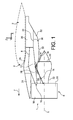
- This engine assembly 1 is intended to be fixed under a wing 2 of this aircraft. It comprises a mast or attachment device 4, as well as a motor 6 such as a turbojet engine hung under this device 4.
- the attachment device 4 comprises a rigid structure 8, also called a primary structure, carrying means for attaching the motor 6, these attachment means having a plurality of engine attachments 10, 12, and a device for taking up the thrust forces 14 generated by the engine 6.
- the assembly 1 is intended to be surrounded by a nacelle (not shown), and that the attachment pylon 4 comprises another series of fasteners (not shown) reported on the rigid structure 8 and to ensure the suspension of this assembly 1 under the wing 2 of the aircraft.
- X the longitudinal direction of the mast 4 which is also comparable to the longitudinal direction of the turbojet engine, this direction X being parallel to a longitudinal axis 5 of the turbojet engine 6.
- Y is called the direction oriented transversely to the mast 4 and also comparable to the transverse direction of the turbojet engine 6, and Z the vertical direction or height, these three directions X, Y and Z being orthogonal to each other.
- front and rear are to be considered in relation to a direction of advancement of the aircraft encountered following the thrust exerted by the turbojet engine 6, this direction being represented schematically by the arrow 7.
- turbojet engine 6 has at the front of a large fan casing 18 delimiting an annular fan duct 20, and comprises a rearward central casing 22 of smaller size, enclosing the core of this fan. turbojet. Housings 18 and 22 are of course integral with each other.
- the engine fasteners 10, 12 of the device 4 are provided in the number of two, respectively called front engine attachment and rear engine attachment.
- the forward engine attachment 10 is interposed between a front end of the rigid structure 8, and an upper portion of the fan casing 18.
- the rear engine attachment 12 is interposed between the rigid structure 8 and the central casing 22, or the throttle housing located further back.
- the rigid structure 8 makes it possible to ensure the transmission of forces between the turbojet and the wing. It takes the form of a box extending from the rear to the front, substantially in the direction X. This metal box is then conventionally formed by the assembly of upper and lower spars and side panels connected together by intermediate transverse stiffening ribs (not visible on the figure 1 ), each of which takes the form of a rectangle oriented in a plane YZ.
- one of the secondary structures of the mast 4 is a front aerodynamic structure 24, a rear aerodynamic structure 26, a connecting fairing 28 of the forward and aft aerodynamic structures, and a lower rear aerodynamic fairing 30, also called “shield” or “APF”. "(Aft Pylon Fairing).
- the front aerodynamic structure 24 is placed in the lower front extension of the wing 2 and above the primary structure 8. It is fixedly mounted on the rigid structure 8, and has an aerodynamic profile function between an upper part fan cowls hinged thereto, and the leading edge of the wing.
- This aerodynamic structure before 24 then has not only an aerodynamic fairing function, but also allows the introduction, the segregation and routing of different systems (air, electrical, hydraulic, fuel).
- the front part of this structure 24 is not in contact with the rigid structure 8, it is usually interposed a heat exchanger in the space defined between these two elements.
- the connecting fairing 28 Directly in the rear extension of this structure 24, still under the wing and mounted above the rigid structure 8, is the connecting fairing 28, also called “karman". Then, still towards the rear, the connecting fairing 28 is extended by the rear aerodynamic structure 26, which contains a part of the equipment of the mast. This structure 26 is preferably located entirely rearward with respect to the rigid structure 8, and is therefore attached under the wing of the aircraft.
- the lower rear aerodynamic fairing 30 also called “shield” or "Aft Pylon Fairing”. Its essential functions are the formation of a thermal barrier, also called fireproof, to protect the mast and the canopy from the heat released by the primary flow, and the formation of an aerodynamic continuity between the engine output and the engine mast. hooking.
- the fairing 30 above has a thermal protection floor 32 provided with an outer surface designed to be wedged by a primary flow of the motor which it delimits partially radially outwards, this primary flow escaping from the nozzle 33 of the engine being shown schematically by the arrow 36.
- the fairing 30 also comprises two side panels 44 which are in turn provided to be matched externally by a secondary flow of the motor shown schematically by the arrow 38, because of their location in the annular channel 40 of secondary flow of the engine, and / or at the output thereof.
- the floor 32 for thermal protection of the mast and the wing vis-à-vis the primary flow 36 is a lower portion of the shroud 30.
- this floor is an upper portion of the fairing in the alternative case where the engine is intended to be implanted above the wing.
- the mast incorporates a thrust recovery device comprising, as disclosed in particular in the document WO 2007/000456 two lateral rods arranged symmetrically with respect to each other.
- One end of each connecting rod is mounted articulated on a spreader, itself mounted hinged to a bracket integral with the rigid structure of the attachment pylon.
- the other end of each connecting rod is mounted on the crankcase of the engine, preferably on the intermediate crankcase.
- the invention therefore aims to remedy at least partially the disadvantage mentioned above, relating to the achievements of the prior art.
- the subject of the invention is a device for taking up the thrust forces for an aircraft engine mount, said device comprising a first fitting intended to be secured to a rigid structure of the suspension pylon, as well as two lateral rods of recovery of the thrust forces.
- it further comprises an axle system carrying three first male rod members arranged along the latter and respectively belonging to a primary ball joint and two secondary ball joints arranged on either side of said primary ball joint.
- said first fitting incorporating a second female ball member cooperating with said first member of said primary ball joint, and one end of each of the two connecting rods incorporating a second female ball member cooperating respectively with said first members of the two secondary ball joints.
- the invention is remarkable in that it proposes a design of a device for taking up thrust forces that differ radically from previous designs, based on the use of a rudder.
- This lifter is indeed removed in favor of a system axis, preferably oriented transversely, bearing three ball joints, the two laterally allow the connection of connecting rods.
- the axis system passes through three coaxial bores made respectively in the first three male spherical members.
- the centers of the primary and secondary ball joints are aligned.
- the device also comprises two second fittings intended to be integral with the rigid structure of the attachment pylon, the second fittings being arranged such that each secondary ball is arranged between one of these second fittings and the primary ball joint , in the direction of the axis system, and each second fitting is traversed with clearance by said axis system.
- the other end of the lateral rods for taking up the thrust forces is intended to be connected to the engine, preferably on the intermediate casing thereof.
- the subject of the invention is also an aircraft engine attachment pylon comprising a rigid structure as well as a thrust force recovery device as described above.
- the invention also relates to an engine assembly for an aircraft comprising a motor attachment pylon as described above, and a motor attached to said mast, preferably of the turbojet or turboprop type.
- the invention relates to an aircraft comprising at least one engine assembly as described above.
- FIG. 2 an exploded view of an engine assembly 1 for an aircraft intended to be fixed under a wing 2 of this aircraft, this assembly 1 comprising a coupling device 4 according to a preferred embodiment of the present invention. invention, as well as a motor 6 such as a turbojet engine hung under this device 4.
- the attachment pylon 4 comprises a rigid structure 108, also called a primary structure, carrying means for fastening the engine 6, these attachment means having a plurality of engine attachments 10, 12 (each shown in part only on the figure 2 ), as well as a device for taking up the thrust forces 14 generated by the engine 6.
- the assembly 1 is intended to be surrounded by a nacelle (not shown), and that the attachment pylon 4 comprises another series of fasteners 109, 109 'reported on the rigid structure 108 and to ensure the suspension of this assembly 1 under the wing / wing 2 of the aircraft.
- Each of the wing fasteners 109, 109 ' is also shown only in part on the figure 2 .
- the engine fasteners 10, 12 of the mast 4 are provided in the number of two, respectively called front engine attachment and rear engine attachment.
- the front engine attachment 10 is interposed between a front end of the rigid structure 108 and an upper portion of the fan casing 18, while the rear engine attachment 12 is itself interposed between the rigid structure 8 and the central casing 22, or the ejection housing located further back.
- the device for taking up the thrust forces 14 which is also the subject of the invention, generally comprises an axle system carrying three ball joints connecting the connecting rods to the rigid structure 108, as will be detailed later, with reference to FIGS. Figures 6 to 8 .
- the rigid structure 108 firstly comprises a box 150 extending generally in the direction X.
- the box is formed from a single hollow section made in one piece composite material, resin mix type and carbon fiber and / or glass, for example CFRP (English “Carbon Fiber Reinforced Plastic”).
- this type of box can be easy and varied. It consists for example in arranging folds of composite material on a male mold, then placing the set of folds inside a lightweight female mold, which will ensure a precise shape to the outer surface of the box. This is achieved by the application of fluid pressure from the inside of the box, which acts as a compacting force against the inner surface of the box placed in a suitable furnace.
- the stack of folds may include stiffeners, located at predetermined locations of the box, whose interior surface does not require any particular finish.
- Stiffeners thermoplastics can also be added to the box after the formation thereof, on its outer surface and / or its inner surface. Nevertheless, it is preferably provided that the interior of the box 150 remains empty. It is in particular devoid of transverse stiffening ribs which, here, are provided outside the box, as will be detailed below.
- the casing 150 has a cross section of substantially square or rectangular shape, with angles that can be slightly rounded, which facilitates its production of composite material.
- stiffening transverse ribs surround and marry the outer surface of the box. Therefore, ribs incorporating a substantially square / rectangular frame that fits the box can then have reinforced areas at their corners, since these can incorporate material to fill the outside spaces left empty by the rounded corners of the box. . The stiffness of the ribs is reinforced.
- the box 150 has a section of maximum size at the two front wing fasteners 109, 109 it carries. From this region of maximum size, the box extends longitudinally both a short distance to the rear, and a greater distance forward, with a section of magnitude that weakens, and of course one taking, even if two longitudinal sections could be envisaged, without departing from the scope of the invention.
- the rigid structure 108 is completed by a plurality of transverse ribs 152 for stiffening the box, fixed externally on the box 150 they surround by marrying its outer surface. In addition, they are spaced from each other in the X direction.
- Each of these ribs 152 oriented in a YZ plane, preferably has a square / rectangular frame whose four sides respectively marry the upper and lower uprights and the two lateral sides of the box. In this way, each of them surrounds the single section of box, on which they are fixed by welding, bolting, or by any other conventional technique available to the skilled person.
- each rib 152 is inserted from a reduced section end of the box, then moved relative to the latter until its frame bears on the outer surface of the box, at its final location. At this stage, before or after fixing the rib on the box, it can be readjusted thermoplastically to allow a correct assembly on the rib, being reconformed hot directly on the outer transverse rib.
- the ribs 152 are cleverly used for supporting one or more other mast equipment, or the nacelle intended to surround the engine. They therefore have support means for these devices, preferably made in one piece with the ribs.
- two of the front ribs 152 have, at the lateral sides of their frame, support means 154 of articulated nacelle covers (not shown), these means 154 taking the form of fittings drilled in direction X in order to accommodate suitable hinges.
- One of the front ribs 152 has, at the lower side of its frame, support means 156 of the rear engine attachment 12. These means 156 take the form of a support plate pointing downwards, on which is bolted to a fitting 157 forming an integral part of the rear engine attachment 12.
- the rear engine attachment is completed by another fitting (not shown) integral with the central casing 22 of the engine or realized in one piece with it, connected to the fitting 157 by means of rods and / or hinges articulated on each of the two fittings.
- the foremost rib 152 has, at the lower side of its frame, support means 159 of the forward engine attachment 10.
- These means 159 take the form of a support plate facing the base, on which is bolted a fitting 161 forming an integral part of the front engine attachment 10.
- the front engine attachment is completed by another fitting (not shown) integral with the fan case 18 of the engine or made in one piece with it, connected to the fitting 159 by means of links and / or shackles hinged to each of the two fittings.
- the box 150 supports, at its maximum size section, a rib 152 equipped with support means 163 of the two front wing fasteners 109, 109.
- These means 163 take, for each of the two fasteners 109, 109 arranged substantially symmetrically on either side of a vertical and longitudinal median plane of the box 150, the shape of a support plate laterally oriented, and corresponding to the upper part of one of the lateral sides of the frame of the rib 152.
- On each of the two plates 163 is bolted a fitting 165 forming an integral part of the relevant front wing attachment.
- each front wing attachment 109 is completed by another fitting (not shown) integral with a wing spar or made in one piece with it, connected to the fitting 165 by means of rods and / or shackles articulated on each of the two fittings.
- ribs 152 have, at the lower side of their frame, support means 158 of a thermal protection floor 32. These means take the form of a rib extension downwards, which ends by a convex surface 160 receiving the floor 32 of complementary shape, the outer surface 164 is intended to be married by a primary flow 36 of engine. With this arrangement, the fairing 30 used in the prior art, called APF, is advantageously no longer required.
- the ribs 152 also have, at the lower side of their frame, support means 166 of a ventilated system 170 for thermal protection of the box.
- These means 166 can take different forms, such as that of a mounting plate, on which is mounted the ventilated system 170 taking generally the shape of a duct extending longitudinally from one end to the other of the box, under the lower amount of it. This duct may also pass through the lower rib extension 158 of one or more rear ribs 152, as shown in FIG. figure 2 .
- this conduit By being traversed by a cool fluid circulating downstream, this conduit, known per se, therefore performs a function of thermal protection of the box vis-à-vis the heat released by the engine.
- the ribs 152 have means for supporting an aerodynamic skin of the mast, referenced 172 on the figure 2 .
- These support means correspond to the edges of the ribs, which provide a skin support surface 172.
- the skin 172 possibly obtained by the assembly of panels, is provided to constitute the aerodynamic surface of the skin. all the aerodynamic fairings encountered in the prior art shown on the figure 1 , namely the aerodynamic structure before 24, the rear aerodynamic structure 26, the connection fairing 28 and the lower rear aerodynamic fairing 30.
- the skin 172 is therefore provided to cover, at a distance, the entirety of the upper upright and side flanks of the box 150.
- the front ribs have an upper extension 178 of arched outward shape, said arch, to correspond to the identical shape of the upper portions of the front aerodynamic structure 24 and the front portion of the connecting fairing 28.
- the ribs the rear end have an upper extension 180 of inwardly curved shape, said hollow, to correspond to the identical shape of the upper parts of the rear aerodynamic structure 26 and the rear portion of the connecting fairing 28.
- the upper extension 178 of the front ribs 152 is concave for the reception of the skin portion 172 of complementary shape
- the upper extension 180 of the rear ribs 152 is convex for the reception of the skin portion 172 of complementary shape , or for the direct reception of the intrados surface of the wing 2 of complementary shape.
- the upper extension 178 of the arches-shaped front ribs may be traversed by a pipe of the mast, for example a heat exchanger duct 182, running along the upper upright of the casing 150.
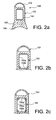
- the box 150 made of a single piece of composite material, of substantially shaped cross section rectangular, with rounded corners.
- Each rib 152 wife, with its frame, the outer surface of this box, all around it.
- the frame of the rib internally defines a contact surface along a closed line, on which the box is in contact, and on which it can be reconformed hot after manufacture, thanks to its thermoplastic properties.
- the four corners of the frame of the rib have a reinforced mechanical strength, due to the presence of material filling spaces left free by the rounded corners of the box, married by these corners of the frame. It is advantageously the entire rib that sees its increased mechanical strength.
- the box 150 which is no longer made in one piece, but obtained from the assembly of a lower spar 150b titanium alloy, and a U-shaped upper structure 150a made of a single piece of composite material.
- the U-shaped structure thus forms the upper amount of the box, as well as its side flanks.
- the lower spar 150b forming the lower upright of the box allows, thanks to the titanium alloy, to better withstand the heat released by the engine opposite which it is.
- the assembly of the U-shaped upper structure 150a on the lower spar 150b can be carried out conventionally, for example by bolting.
- the Figure 2c represents a second alternative embodiment, resulting from the first since it consists in producing the U-shaped upper structure using two lateral panels 150a 'and an upper spar 150a "fixed to each other, and each made of composite material .
- the rib 152 the front of the rigid structure is made in one piece with the fitting 161 forming part of the engine attachment 10.
- This bracket 161 extends laterally from the side and other rib frame 152, and also down from the bottom side of this frame. It carries a plurality of rods / shackles 185 which are mounted at one of their ends, preferably in an articulated manner, on this fitting 161, and which are mounted at the other of their ends, preferably also articulated, on a other fitting 184 integral with an upper portion of the fan casing 18, or made in one piece with the latter.
- two rods / shackles 185 are provided, respectively mounted at the lateral ends of the fastener 10.
- the central portion of the fitting 161 is also mounted articulated on a central portion of the fitting 184.
- This assembly is preferably of the "waiting" type, namely that the efforts do not transit in normal configuration, but only in emergency configuration when one of the two lateral parts of the fastener 10 is damaged. This central part therefore performs a so-called security function, also called "Fail Safe".
- the hinge pins are here oriented in the X direction.
- one of the ribs 152 is made in one piece with the fitting 157 forming part of the engine attachment 12.
- This fitting 157 extends substantially down from the lower side of the rib frame 152. It carries a plurality of rods / shackles 187 which are mounted at one of their ends, preferably in an articulated manner, on this fitting 157, and which are mounted at the other of their ends, preferably also articulated, on another fitting (not shown) secured to an upper portion of the central casing 22, or made in one piece with the latter.
- two rods / shackles 187 are provided, respectively mounted at the lateral ends of the fastener 12.
- the central portion of the fitting 157 is also mounted articulated on a central portion of the fitting attached to the housing 22
- This arrangement is preferably of the "waiting" type, namely that the forces do not transit in normal configuration, but only in emergency configuration when one of the two lateral parts of the fastener 10 is damaged.
- This part Central thus also fulfills a "Fail Safe" function.
- the hinge pins are oriented in the X direction.
- the front wing attachment 109 is designed according to an alternative embodiment. Indeed, it is here provided that one of the ribs 152 is made in one piece with the fitting 165 forming part of the fastener 109.
- This fitting 165 extends substantially upwards from a corner between a lateral side and the upper side of the rib frame 152. It forms a yoke on which is mounted a rod / shackle 188 which is mounted at one of its ends, preferably in an articulated manner, on this yoke, and which is mounted on the other of its ends, preferably also articulated, on another fitting (not shown) integral with a front spar of the wing, or made in one piece with the latter.
- the hinge pins are here oriented in the Y direction.
- the fitting 165 made in one piece with the rib 152 is doubled by another bracket 165 ', which is superimposed along the Y direction.
- a rod / shackle 188 then connects the clevis-shaped fitting 165 'to the wing fitting in a manner similar to that used for the fitting 165 described above.
- the same hinge axis can pass through the two clevises housing the shackles 188, as has been shown on the figure 5 .
- the additional fitting 165 ', pressed against the fitting 165 is preferably fixed by bolting to the lateral side of the rib frame 152 incorporating the same fitting 165.
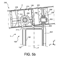
- FIG. 5a to 5c there is shown an assembly 200 comprising the mast 4 and the wing 2, assembly in which the two front wing fasteners 109 are made according to yet another alternative.
- the attachment means of the rigid structure 108 on the wing 2 are constituted by the two front wing fasteners 109, and by the rear wing attachment 109 '.
- the latter which is connected to a portion of the wing arranged rearwardly relative to the front wing spar 201, has a conventional shape, of the type consisting of the assembly of fittings and shackles / rods. It will not be described further.
- the two fasteners before 109, 109 are on the other hand no longer symmetrical, but always disposed of on either side of a vertical and longitudinal median plane P of the mast. They are preferably traversed by the same fictitious transversal plane of the mast.
- the first fastener before 109 the one on the bottom figure 5a it has a first shear pin 202 oriented in the Y direction. It also incorporates a mast fitting 204 attached to a side blank of the box 150, between two ribs 152, and protrudes upwardly from the upper post of the box. The protruding portion, oriented in an XZ plane, defines an orifice traversed by the pin 202. As shown on the Figures 5a to 5c , for safety reasons, the mast fitting 204 may be doubled by an additional mast fitting 204 ', which therefore performs a "Fail Safe" function.
- the fitting 204 ' is for example fastened superimposed on the fitting 204, in the direction Y. It is also traversed by the pin 202.
- One and / or the other of these fittings 204, 204' are preferably also fixed on the sides of the frames of the two ribs between which they are located, as is best seen on the figure 5c .
- this front wing attachment comprises a wing fitting 206, substantially oriented in an XZ plane, and attached fixedly to the front spar 201. It thus protrudes forwardly with respect to the latter, to one end. clevis-shaped front housing the rear end of the mast fitting 204, and is also traversed by the pin 202.
- the wing fitting 206 may be doubled by an additional wing fitting 206 ', which therefore performs a "Fail Safe" function.
- the fitting 206 ' is for example fixed superimposed on the fitting 206, in the Y direction. Its front end in the form of a yoke, which houses the rear end of the fitting 204', is also traversed by the pin 202.
- the second attachment before 109 the one from the top on the figure 5a , it has a second shear pin 208 oriented in the X direction. It also incorporates a mast fitting 210 integral with the rigid structure, which is preferably made in one piece with one of the stiffening ribs 152. Indeed , this fitting 210 pierced with an orifice traversed by the pin 208 extends from the upper side of the frame of the rib 152, in a plane YZ. It also carries a ball 212 establishing the mechanical connection with the shear pin 208.
- the fastener 109 also comprises a fitting housing of the pin 214 integral with the front spar 201. It is fixed on the front spar 201 by bolting, in front of it. It therefore has a rear bearing surface on the spar 201, which is inclined in the same direction as the latter, that is to say, inclined at the same time in the directions X and Y. Moreover, it has a surface before entering a plane YZ facing the mast fitting 210. It is traversed by a pin housing hole, for embedding the pin in the fitting 214.
- this pin housing fitting 214 is arranged between the front spar 201 and the mast fitting 210, in the direction X.
- an additional housing housing the pin 214 ' visible on the figure 5a . It is secured to the front spar 201, bolted on it so that the spar is located between the two fittings 214, 214 '. Furthermore, it has a pin housing hole in the continuity of the hole made in the spar 201, itself located in the continuity of the hole of the fitting 214. The pin 208 thus passes successively through the fitting housing the pin 214, the front spar 201, and the additional housing housing the pin 214 '.
- a support for holding the pin 216 arranged so that the mast fitting 210 is located between the fitting housing of the pin 214 and the fitting for holding the pin 216.
- the fitting 216 is oriented substantially in a plane YZ, parallel to the mast fitting 210 to which it faces. It is fixed to the front spar 210 directly at one of its ends, preferably by bolting, and indirectly to the other of its ends, by means of a connecting fitting 218.
- the latter which is preferably oriented substantially in the X direction, is provided to compensate for the inclination of the front spar 201 in the direction Y.
- the fittings 216, 218 and the front spar 201 form a right-angled triangle in which the fittings 210, 214, and which is traversed by the peg 208 passing successively through the fitting 216, the fitting 210, the fitting 214, the spar 201 and the fitting 216 '.
- the fitting 216 can also be doubled by an additional pion holding fitting 216 ', again for safety reasons. This fitting 216 'is then fixed superimposed on the fitting 216, in the direction X.
- the front wing attachment 109 of the bottom makes it possible to ensure the recovery of the forces exerted along the X and Z directions, while that of the top makes it possible to ensure the recovery of the forces exerted along the directions. Y and Z.
- the rear wing attachment 109 ' also makes it possible to ensure the recovery of forces exerted along the Y and Z directions. Consequently, these three wing fasteners which make up the attachment means allowing a recovery of isostatic efforts.
- the device 14 nevertheless retains two side connecting rods for resetting the thrust forces, referenced 14a, arranged symmetrically with respect to the vertical and longitudinal median plane P of the mast.
- These two connecting rods 14a conventionally drive forwards and upwards from the intermediate casing of the motor on which their front end is mounted, preferably in an articulated manner.
- the axes of articulation of the connecting rods 14a on the intermediate casing are each substantially perpendicular to the common plane in which the two connecting rods are inscribed.
- the device 14 comprises an axis system 190, oriented in the Y direction, under the lower upright of the casing 150.
- This axis system comprises for example two concentric axes 190a, 190b, as is schematized on FIG. figure 6 . This doubling of the axis makes it possible to obtain a "Fail Safe" safety function, in the event of the rupture of one of them.
- the axis system comprises a single axis, preferably cylindrical of circular section, or a plurality of concentric axes, also cylindrical of circular sections.
- the axis system 190 carries three ball joints whose centers are aligned on the longitudinal axis 191 of the system 190, oriented in the Y direction.
- a primary ball joint 192 made from a first male ball joint member 192a, slipped around the axis system 190, and a second female ball member 192b, integrated with a first fitting 194.
- the male and female members are naturally shaped complementary to form the ball 192, this shape corresponding to a sphere truncated symmetrically by two parallel planes between them and orthogonal to the axis 191.
- the female ball member 192b is either a fixed insert on the fitting 194, or integral with it.
- This same fitting 194 is fixedly mounted on the rigid structure 108, for example between two directly consecutive rib frames 152.
- the first fitting 194 may in fact have a base in abutment and fixed on the lower side of the two rib frames 152, as well as on the portion of the lower upright of the box 150 located between the two ribs.
- the assembly is preferably carried out by bolting on the box and the two ribs concerned, the rear rib of which is preferably that integrating the fitting 157 of the rear engine attachment 12.
- the male and female members are here also of complementary shapes to form the ball joints 196, this shape corresponding to a sphere truncated symmetrically by two parallel planes between them and orthogonal to the axis 191.
- the female ball member 196b is either a fixed insert on the rear end of the rod 14a or is integral with it.
- the three male ball joint members 192a, 196a thus each have a through hole in the Y direction, allowing to slide around the axis system 190.
- Their translation retention with respect to this system 190, in the direction of the 191 axis, is provided by the presence of two sockets 198 integral part of the system 190, which plate these bodies 192a, 196a against each other. The latter are also preferably directly in support of each other, as shown on the figure 6 .
- the bushes 198 are in turn maintained for one of them by the head of the axis system, and for the other by the nut of this system, arranged opposite the head.
- the device 14 has backup means for ensuring the transmission of forces in case of failure.
- These means comprise two second fittings 199 fixedly mounted on the rigid structure 108, preferably on the lower upright of the casing 150.
- the two second fittings 199 are located at the lateral ends of the device 14, so that each secondary ball 196 is arranged between one of these second fittings 196, and the primary ball 192, in the direction of the axis system.
- every second fitting 196 is traversed with clearance by the axis system 190, at the level of the locking bushes 198.
- the two fittings 196 extend in XZ planes, as the first bracket 194 located therebetween.
- the drive forces pass successively through the two links 14a, the two secondary joints 196, the axis system 190, the primary ball 192, the first fitting 194, and the rigid structure 108 of the mast. hooking.
- the axis system 190 can then slightly oscillate along the center of the primary ball joint 192, preferably in the plane of the connecting rods, because of the permanent balancing of the forces passing through the two connecting rods.
- the device 14 is designed so that the oscillations of the axis system are of sufficiently small amplitude so that it does not abut against the second fittings 199, through which no effort passes in normal flight conditions.
Landscapes
- Engineering & Computer Science (AREA)
- Aviation & Aerospace Engineering (AREA)
- Structures Of Non-Positive Displacement Pumps (AREA)
- Body Structure For Vehicles (AREA)
- Mutual Connection Of Rods And Tubes (AREA)
Applications Claiming Priority (1)
| Application Number | Priority Date | Filing Date | Title |
|---|---|---|---|
| FR1057963A FR2965549B1 (fr) | 2010-10-01 | 2010-10-01 | Dispositif de reprise de poussee a bielles pour mat d'accrochage d'un moteur d'aeronef, integrant trois rotules alignees |
Publications (2)
| Publication Number | Publication Date |
|---|---|
| EP2436601A1 true EP2436601A1 (de) | 2012-04-04 |
| EP2436601B1 EP2436601B1 (de) | 2013-11-13 |
Family
ID=43924183
Family Applications (1)
| Application Number | Title | Priority Date | Filing Date |
|---|---|---|---|
| EP11182682.2A Not-in-force EP2436601B1 (de) | 2010-10-01 | 2011-09-26 | Vorrichtung zur Aufnahme der Schubkräfte eines Triebwerks mit drei in Reihe angeordneten Kugelgelenken |
Country Status (4)
| Country | Link |
|---|---|
| US (1) | US8613404B2 (de) |
| EP (1) | EP2436601B1 (de) |
| CN (1) | CN102442433B (de) |
| FR (1) | FR2965549B1 (de) |
Cited By (9)
| Publication number | Priority date | Publication date | Assignee | Title |
|---|---|---|---|---|
| FR3014841A1 (fr) * | 2013-12-17 | 2015-06-19 | Airbus Operations Sas | Ensemble pour aeronef comprenant un corps d'attache moteur en partie realise d'une seule piece avec une nervure interieure de rigidification d'un caisson de mat d'accrochage |
| US9868545B2 (en) | 2013-12-19 | 2018-01-16 | Airbus Operations (S.A.S.) | Primary structure for an attachment pylon with firewall and thermal layers |
| FR3054827A1 (fr) * | 2016-08-08 | 2018-02-09 | Aircelle | Element de fixation pour nacelle de turboreacteur d’aeronef et ensemble propulsif comportant un tel element |
| US9889943B2 (en) | 2013-12-17 | 2018-02-13 | Airbus Operations (S.A.S.) | Assembly for an aircraft, comprising an engine attachment body equipped with at least one shackle support fitting that passes into the box section of the attachment pylon |
| FR3065442A1 (fr) * | 2017-04-25 | 2018-10-26 | Airbus Operations | Ensemble moteur pour aeronef comprenant une attache moteur avant integree au caisson du mat d'accrochage |
| US10336458B2 (en) | 2013-12-23 | 2019-07-02 | Airbus Operations (S.A.S.) | Aircraft assembly comprising a mounting strut built into the nacelle and arranged at the rear section of the fuselage |
| FR3096344A1 (fr) * | 2019-05-21 | 2020-11-27 | Airbus Operations | Systeme d’attache moteur avant pour un moteur d’aeronef comportant une fixation directe entre le mat reacteur et le moteur |
| FR3096352A1 (fr) * | 2019-05-24 | 2020-11-27 | Airbus Operations | Ensemble de motorisation pour un aeronef comprenant un support de charge |
| FR3121428A1 (fr) * | 2021-04-02 | 2022-10-07 | Airbus Operations | Mât réacteur d’aéronef comportant un ensemble mobile de capots |
Families Citing this family (18)
| Publication number | Priority date | Publication date | Assignee | Title |
|---|---|---|---|---|
| FR2969578B1 (fr) * | 2010-12-27 | 2013-02-08 | Snecma | Dispositif de suspension d'un turboreacteur |
| CN103032434B (zh) * | 2012-11-26 | 2016-05-04 | 中国商用飞机有限责任公司 | 破损安全保险销 |
| FR3000467A1 (fr) * | 2012-12-28 | 2014-07-04 | Airbus Operations Sas | Manille a trois points a capacite de filtrage de vibrations et attache moteur d'aeronef equipee d'une telle manille |
| CN103101628B (zh) * | 2013-02-06 | 2015-05-27 | 中国商用飞机有限责任公司 | 一种与飞机吊挂一体化的前安装节 |
| US8979020B2 (en) * | 2013-06-07 | 2015-03-17 | Pratt & Whitney Canada Corp. | Mounting system for mounting engine nacelle components and associated method |
| US10144524B2 (en) * | 2013-06-14 | 2018-12-04 | Rohr, Inc. | Assembly for mounting a turbine engine to a pylon |
| CN105392700B (zh) | 2013-07-26 | 2018-12-18 | Mra系统有限责任公司 | 飞行器发动机吊架 |
| CN110182373B (zh) * | 2015-01-07 | 2023-01-10 | 洛德公司 | 用于飞行器发动机安装架的轴承组件 |
| FR3032180B1 (fr) * | 2015-01-30 | 2018-05-18 | Airbus Operations | Ensemble propulsif comportant un turboreacteur et un mat d'accrochage permettant une nouvelle distribution des efforts entre le turboreacteur et la voilure |
| US11203437B2 (en) * | 2016-06-30 | 2021-12-21 | Bombardier Inc. | Assembly and method for conditioning engine-heated air onboard an aircraft |
| FR3059645B1 (fr) * | 2016-12-02 | 2018-12-07 | Safran Aircraft Engines | Dispositif de suspension pour turbomachine |
| WO2018102183A1 (en) * | 2016-12-03 | 2018-06-07 | Ge Aviation Systems Llc | Spherical bearing system |
| FR3086925B1 (fr) * | 2018-10-08 | 2020-09-11 | Safran Aircraft Engines | Ensemble de suspension pour une turbomachine |
| US12024305B2 (en) * | 2021-10-28 | 2024-07-02 | Honeywell International Inc. | Pylon system for coupling engine to vehicle |
| US11884410B2 (en) | 2022-02-04 | 2024-01-30 | General Electric Company | Dual function links for gas turbine engine mounts |
| US12509999B2 (en) | 2023-09-25 | 2025-12-30 | General Electric Company | Viscous damper apparatus and associated methods to control a response to a resonant vibration frequency |
| US12319419B2 (en) | 2023-09-25 | 2025-06-03 | General Electric Company | Fluid-filled thrust link apparatus and associated method |
| US12529323B2 (en) | 2023-09-25 | 2026-01-20 | General Electric Company | Variable diameter thrust link apparatus |
Citations (4)
| Publication number | Priority date | Publication date | Assignee | Title |
|---|---|---|---|---|
| EP1136355A1 (de) * | 2000-03-22 | 2001-09-26 | Eads Airbus SA | Schubbefestigung eines Triebwerkes an einem Luftfahrzeug |
| WO2007000456A1 (fr) | 2005-06-29 | 2007-01-04 | Airbus France | Mat d'accrochage de moteur pour aeronef |
| FR2917713A1 (fr) * | 2007-06-21 | 2008-12-26 | Airbus France Sas | Dispositif d'accrochage de moteur d'aeronef et aeronef comportant au moins un tel dispositif. |
| WO2009037267A1 (fr) | 2007-09-20 | 2009-03-26 | Airbus France | Carenage aerodynamique arriere inferieur pour dispositif d'accrochage d'un moteur d'aeronef |
Family Cites Families (8)
| Publication number | Priority date | Publication date | Assignee | Title |
|---|---|---|---|---|
| FR2774358B1 (fr) * | 1998-02-04 | 2000-04-21 | Aerospatiale | Dispositif d'accrochage d'un moteur d'aeronef |
| US6330995B1 (en) * | 2000-02-29 | 2001-12-18 | General Electric Company | Aircraft engine mount |
| FR2855495B1 (fr) * | 2003-05-27 | 2006-11-24 | Snecma Moteurs | Dispositif d'accrochage avant de moteur d'avion |
| FR2856656B1 (fr) * | 2003-06-30 | 2006-12-01 | Snecma Moteurs | Suspension arriere de moteur d'avion avec bielles de reprise de poussee et palonnier en forme de boomerang |
| FR2867155B1 (fr) * | 2004-03-08 | 2007-06-29 | Snecma Moteurs | Suspension d'un moteur a la structure d'un avion |
| FR2883256B1 (fr) * | 2005-03-18 | 2008-10-24 | Airbus France Sas | Attache moteur d'un systeme de montage interpose entre un mat d'accrochage et un moteur d'aeronef |
| FR2903382B1 (fr) * | 2006-07-10 | 2008-10-10 | Airbus France Sas | Dispositif d'accrochage d'un moteur d'aeronef comportant deux bielles de reprise de poussee a emboitement transversal |
| FR2920138B1 (fr) * | 2007-08-24 | 2010-03-12 | Airbus France | Dispositif d'accrochage de moteur d'aeronef comportant un dispositif de reprise des efforts de poussee a encombrement reduit |
-
2010
- 2010-10-01 FR FR1057963A patent/FR2965549B1/fr not_active Expired - Fee Related
-
2011
- 2011-09-22 US US13/239,939 patent/US8613404B2/en active Active
- 2011-09-26 EP EP11182682.2A patent/EP2436601B1/de not_active Not-in-force
- 2011-10-08 CN CN201110306769.2A patent/CN102442433B/zh not_active Expired - Fee Related
Patent Citations (4)
| Publication number | Priority date | Publication date | Assignee | Title |
|---|---|---|---|---|
| EP1136355A1 (de) * | 2000-03-22 | 2001-09-26 | Eads Airbus SA | Schubbefestigung eines Triebwerkes an einem Luftfahrzeug |
| WO2007000456A1 (fr) | 2005-06-29 | 2007-01-04 | Airbus France | Mat d'accrochage de moteur pour aeronef |
| FR2917713A1 (fr) * | 2007-06-21 | 2008-12-26 | Airbus France Sas | Dispositif d'accrochage de moteur d'aeronef et aeronef comportant au moins un tel dispositif. |
| WO2009037267A1 (fr) | 2007-09-20 | 2009-03-26 | Airbus France | Carenage aerodynamique arriere inferieur pour dispositif d'accrochage d'un moteur d'aeronef |
Cited By (14)
| Publication number | Priority date | Publication date | Assignee | Title |
|---|---|---|---|---|
| US9862497B2 (en) | 2013-12-17 | 2018-01-09 | Airbus Operations (S.A.S.) | Assembly for an aircraft, comprising an engine attachment body partially produced in one piece with an internal stiffening rib of an attachment pylon box section |
| FR3014841A1 (fr) * | 2013-12-17 | 2015-06-19 | Airbus Operations Sas | Ensemble pour aeronef comprenant un corps d'attache moteur en partie realise d'une seule piece avec une nervure interieure de rigidification d'un caisson de mat d'accrochage |
| US9889943B2 (en) | 2013-12-17 | 2018-02-13 | Airbus Operations (S.A.S.) | Assembly for an aircraft, comprising an engine attachment body equipped with at least one shackle support fitting that passes into the box section of the attachment pylon |
| US9868545B2 (en) | 2013-12-19 | 2018-01-16 | Airbus Operations (S.A.S.) | Primary structure for an attachment pylon with firewall and thermal layers |
| US10336458B2 (en) | 2013-12-23 | 2019-07-02 | Airbus Operations (S.A.S.) | Aircraft assembly comprising a mounting strut built into the nacelle and arranged at the rear section of the fuselage |
| FR3054827A1 (fr) * | 2016-08-08 | 2018-02-09 | Aircelle | Element de fixation pour nacelle de turboreacteur d’aeronef et ensemble propulsif comportant un tel element |
| FR3065442A1 (fr) * | 2017-04-25 | 2018-10-26 | Airbus Operations | Ensemble moteur pour aeronef comprenant une attache moteur avant integree au caisson du mat d'accrochage |
| FR3096344A1 (fr) * | 2019-05-21 | 2020-11-27 | Airbus Operations | Systeme d’attache moteur avant pour un moteur d’aeronef comportant une fixation directe entre le mat reacteur et le moteur |
| EP3750811A1 (de) * | 2019-05-21 | 2020-12-16 | Airbus Operations (S.A.S.) | Vorderes motorbefestigungssystem für einen luftfahrzeugmotor, der eine direkte befestigung zwischen dem triebwerksträger und dem motor umfasst |
| US11338929B2 (en) | 2019-05-21 | 2022-05-24 | Airbus Operations (S.A.S.) | Forward engine attachment system for an aircraft engine comprising a direct coupling between the jet engine pylon and the engine |
| FR3096352A1 (fr) * | 2019-05-24 | 2020-11-27 | Airbus Operations | Ensemble de motorisation pour un aeronef comprenant un support de charge |
| US11511873B2 (en) | 2019-05-24 | 2022-11-29 | Airbus Operations Sas | Propulsion assembly for an aircraft, comprising a nacelle load support fastened to a pylon |
| FR3121428A1 (fr) * | 2021-04-02 | 2022-10-07 | Airbus Operations | Mât réacteur d’aéronef comportant un ensemble mobile de capots |
| US11884411B2 (en) | 2021-04-02 | 2024-01-30 | Airbus Operations (S.A.S.) | Aircraft engine pylon having a movable assembly of cowls |
Also Published As
| Publication number | Publication date |
|---|---|
| US20120080555A1 (en) | 2012-04-05 |
| EP2436601B1 (de) | 2013-11-13 |
| FR2965549B1 (fr) | 2013-07-05 |
| US8613404B2 (en) | 2013-12-24 |
| FR2965549A1 (fr) | 2012-04-06 |
| CN102442433B (zh) | 2015-11-25 |
| CN102442433A (zh) | 2012-05-09 |
Similar Documents
| Publication | Publication Date | Title |
|---|---|---|
| EP2436601B1 (de) | Vorrichtung zur Aufnahme der Schubkräfte eines Triebwerks mit drei in Reihe angeordneten Kugelgelenken | |
| FR2965548A1 (fr) | Mat d'accrochage d'un moteur d'aeronef comprenant deux attaches voilure avant a pions de cisaillement orthogonaux | |
| EP2038174B1 (de) | Vorrichtung zur triebwerksbefestigung mit zwei schräg zusammenpassenden schubreaktionsverbindungsstangen | |
| CA2692516C (fr) | Mat d'accrochage de moteur pour aeronef disposant d'un palonnier articule en quatre points | |
| EP2139767B1 (de) | Flugzeugmotorbefestigungsstruktur mit einem hinteren motorankerträger, der sich in einem abstand vom strukturkasten befindet | |
| EP2167384B1 (de) | Gondelstiel zur kupplung eines triebwerks für ein luftfahrzeug mit einem eine rudersteuerstange bildenden hecktriebwerksbefestigungsträger | |
| EP2426051B1 (de) | Strahlturbinenpylon mit fluchtenden vorderen Befestigungspunkten | |
| EP3612445B1 (de) | Anordnung für flugzeug mit einer primärstruktur eines mit einer bolzenverbindung an einem flügelkasten befestigten befestigungspylons | |
| EP2390186B1 (de) | Herstellungsverfahren für eine Rippe zur aerodynamischen Verkleidung eines Triebwerkspylons mittels superplastischer Formung und Verlaschung | |
| EP2146898A1 (de) | Hintere, untere aerodynamische verkleidung für die befestigungsvorrichtung eines flugzeugmotors | |
| FR2931133A1 (fr) | Mat d'accrochage de moteur comprenant des moyens de fixation des longerons et des panneaux agences en dehors de l'espace interieur de caisson | |
| FR2903383A1 (fr) | Dispositif d'accrochage d'un moteur d'aeronef comportant deux bielles de reprise de poussee a double liaison mecanique arriere | |
| CA2699840A1 (fr) | Carenage aerodynamique arriere inferieur pour dispositif d'accrochage d'un moteur d'aeronef | |
| FR3015433A1 (fr) | Ensemble pour aeronef comprenant un mat d'accrochage integre a la nacelle et agence en partie arriere du fuselage | |
| FR2891244A1 (fr) | Mat d'accrochage de moteur pour aeronef | |
| FR2887853A1 (fr) | Attache moteur pour aeronef destinee a etre interposee entre un moteur et un mat d'accrochage | |
| EP2137072A1 (de) | Vorrichtung zur befestigung eines flugzeugtriebwerks und flugzeug mit mindestens einer derartigen vorrichtung | |
| EP2390187A2 (de) | Herstellungsverfahren für eine Rippe einer aerodynamischen Verkleidung eines Triebwerkspylons durch superplastische Verformung und Verlaschung | |
| EP1910167A1 (de) | Anordnung für ein flugzeug mit einem flügelsystemelement und einem befestigungsmast | |
| EP1896325B1 (de) | Triebwerkmontagestruktur für ein flugzeug | |
| WO2006021721A1 (fr) | Ensemble moteur pour aeronef | |
| FR3076282A1 (fr) | Ensemble pour aeronef comprenant une structure primaire de mat d'accrochage fixee a un caisson de voilure par des attaches presentant un encombrement reduit dans la zone de bord d'attaque | |
| FR2891247A1 (fr) | Ensemble pour aeronef comprenant un element de voilure ainsi qu'un mat d'accrochage | |
| EP3437999B1 (de) | Leichte primärstruktur für aufhängemast eines triebwerks eines luftfahrzeugs | |
| FR2965547A1 (fr) | Structure rigide de mat d'accrochage d'un moteur d'aeronef comprenant un caisson en materiau composite renforce par des nervures transversales exterieures |
Legal Events
| Date | Code | Title | Description |
|---|---|---|---|
| PUAI | Public reference made under article 153(3) epc to a published international application that has entered the european phase |
Free format text: ORIGINAL CODE: 0009012 |
|
| AK | Designated contracting states |
Kind code of ref document: A1 Designated state(s): AL AT BE BG CH CY CZ DE DK EE ES FI FR GB GR HR HU IE IS IT LI LT LU LV MC MK MT NL NO PL PT RO RS SE SI SK SM TR |
|
| AX | Request for extension of the european patent |
Extension state: BA ME |
|
| 17P | Request for examination filed |
Effective date: 20120504 |
|
| GRAP | Despatch of communication of intention to grant a patent |
Free format text: ORIGINAL CODE: EPIDOSNIGR1 |
|
| INTG | Intention to grant announced |
Effective date: 20130628 |
|
| GRAS | Grant fee paid |
Free format text: ORIGINAL CODE: EPIDOSNIGR3 |
|
| GRAA | (expected) grant |
Free format text: ORIGINAL CODE: 0009210 |
|
| AK | Designated contracting states |
Kind code of ref document: B1 Designated state(s): AL AT BE BG CH CY CZ DE DK EE ES FI FR GB GR HR HU IE IS IT LI LT LU LV MC MK MT NL NO PL PT RO RS SE SI SK SM TR |
|
| REG | Reference to a national code |
Ref country code: GB Ref legal event code: FG4D Free format text: NOT ENGLISH |
|
| REG | Reference to a national code |
Ref country code: CH Ref legal event code: EP |
|
| REG | Reference to a national code |
Ref country code: AT Ref legal event code: REF Ref document number: 640461 Country of ref document: AT Kind code of ref document: T Effective date: 20131215 |
|
| REG | Reference to a national code |
Ref country code: IE Ref legal event code: FG4D Free format text: LANGUAGE OF EP DOCUMENT: FRENCH |
|
| REG | Reference to a national code |
Ref country code: DE Ref legal event code: R096 Ref document number: 602011003675 Country of ref document: DE Effective date: 20140109 |
|
| REG | Reference to a national code |
Ref country code: NL Ref legal event code: VDEP Effective date: 20131113 |
|
| REG | Reference to a national code |
Ref country code: AT Ref legal event code: MK05 Ref document number: 640461 Country of ref document: AT Kind code of ref document: T Effective date: 20131113 |
|
| REG | Reference to a national code |
Ref country code: LT Ref legal event code: MG4D |
|
| PG25 | Lapsed in a contracting state [announced via postgrant information from national office to epo] |
Ref country code: IS Free format text: LAPSE BECAUSE OF FAILURE TO SUBMIT A TRANSLATION OF THE DESCRIPTION OR TO PAY THE FEE WITHIN THE PRESCRIBED TIME-LIMIT Effective date: 20140313 Ref country code: FI Free format text: LAPSE BECAUSE OF FAILURE TO SUBMIT A TRANSLATION OF THE DESCRIPTION OR TO PAY THE FEE WITHIN THE PRESCRIBED TIME-LIMIT Effective date: 20131113 Ref country code: NL Free format text: LAPSE BECAUSE OF FAILURE TO SUBMIT A TRANSLATION OF THE DESCRIPTION OR TO PAY THE FEE WITHIN THE PRESCRIBED TIME-LIMIT Effective date: 20131113 Ref country code: SE Free format text: LAPSE BECAUSE OF FAILURE TO SUBMIT A TRANSLATION OF THE DESCRIPTION OR TO PAY THE FEE WITHIN THE PRESCRIBED TIME-LIMIT Effective date: 20131113 Ref country code: HR Free format text: LAPSE BECAUSE OF FAILURE TO SUBMIT A TRANSLATION OF THE DESCRIPTION OR TO PAY THE FEE WITHIN THE PRESCRIBED TIME-LIMIT Effective date: 20131113 Ref country code: LT Free format text: LAPSE BECAUSE OF FAILURE TO SUBMIT A TRANSLATION OF THE DESCRIPTION OR TO PAY THE FEE WITHIN THE PRESCRIBED TIME-LIMIT Effective date: 20131113 Ref country code: NO Free format text: LAPSE BECAUSE OF FAILURE TO SUBMIT A TRANSLATION OF THE DESCRIPTION OR TO PAY THE FEE WITHIN THE PRESCRIBED TIME-LIMIT Effective date: 20140213 |
|
| PG25 | Lapsed in a contracting state [announced via postgrant information from national office to epo] |
Ref country code: CY Free format text: LAPSE BECAUSE OF FAILURE TO SUBMIT A TRANSLATION OF THE DESCRIPTION OR TO PAY THE FEE WITHIN THE PRESCRIBED TIME-LIMIT Effective date: 20131113 Ref country code: LV Free format text: LAPSE BECAUSE OF FAILURE TO SUBMIT A TRANSLATION OF THE DESCRIPTION OR TO PAY THE FEE WITHIN THE PRESCRIBED TIME-LIMIT Effective date: 20131113 Ref country code: AT Free format text: LAPSE BECAUSE OF FAILURE TO SUBMIT A TRANSLATION OF THE DESCRIPTION OR TO PAY THE FEE WITHIN THE PRESCRIBED TIME-LIMIT Effective date: 20131113 Ref country code: RS Free format text: LAPSE BECAUSE OF FAILURE TO SUBMIT A TRANSLATION OF THE DESCRIPTION OR TO PAY THE FEE WITHIN THE PRESCRIBED TIME-LIMIT Effective date: 20131113 Ref country code: ES Free format text: LAPSE BECAUSE OF FAILURE TO SUBMIT A TRANSLATION OF THE DESCRIPTION OR TO PAY THE FEE WITHIN THE PRESCRIBED TIME-LIMIT Effective date: 20131113 |
|
| PG25 | Lapsed in a contracting state [announced via postgrant information from national office to epo] |
Ref country code: PT Free format text: LAPSE BECAUSE OF FAILURE TO SUBMIT A TRANSLATION OF THE DESCRIPTION OR TO PAY THE FEE WITHIN THE PRESCRIBED TIME-LIMIT Effective date: 20140313 |
|
| PG25 | Lapsed in a contracting state [announced via postgrant information from national office to epo] |
Ref country code: EE Free format text: LAPSE BECAUSE OF FAILURE TO SUBMIT A TRANSLATION OF THE DESCRIPTION OR TO PAY THE FEE WITHIN THE PRESCRIBED TIME-LIMIT Effective date: 20131113 |
|
| REG | Reference to a national code |
Ref country code: DE Ref legal event code: R097 Ref document number: 602011003675 Country of ref document: DE |
|
| PG25 | Lapsed in a contracting state [announced via postgrant information from national office to epo] |
Ref country code: RO Free format text: LAPSE BECAUSE OF FAILURE TO SUBMIT A TRANSLATION OF THE DESCRIPTION OR TO PAY THE FEE WITHIN THE PRESCRIBED TIME-LIMIT Effective date: 20131113 Ref country code: SK Free format text: LAPSE BECAUSE OF FAILURE TO SUBMIT A TRANSLATION OF THE DESCRIPTION OR TO PAY THE FEE WITHIN THE PRESCRIBED TIME-LIMIT Effective date: 20131113 Ref country code: PL Free format text: LAPSE BECAUSE OF FAILURE TO SUBMIT A TRANSLATION OF THE DESCRIPTION OR TO PAY THE FEE WITHIN THE PRESCRIBED TIME-LIMIT Effective date: 20131113 Ref country code: CZ Free format text: LAPSE BECAUSE OF FAILURE TO SUBMIT A TRANSLATION OF THE DESCRIPTION OR TO PAY THE FEE WITHIN THE PRESCRIBED TIME-LIMIT Effective date: 20131113 |
|
| PLBE | No opposition filed within time limit |
Free format text: ORIGINAL CODE: 0009261 |
|
| STAA | Information on the status of an ep patent application or granted ep patent |
Free format text: STATUS: NO OPPOSITION FILED WITHIN TIME LIMIT |
|
| PG25 | Lapsed in a contracting state [announced via postgrant information from national office to epo] |
Ref country code: DK Free format text: LAPSE BECAUSE OF FAILURE TO SUBMIT A TRANSLATION OF THE DESCRIPTION OR TO PAY THE FEE WITHIN THE PRESCRIBED TIME-LIMIT Effective date: 20131113 |
|
| 26N | No opposition filed |
Effective date: 20140814 |
|
| REG | Reference to a national code |
Ref country code: DE Ref legal event code: R097 Ref document number: 602011003675 Country of ref document: DE Effective date: 20140814 |
|
| PG25 | Lapsed in a contracting state [announced via postgrant information from national office to epo] |
Ref country code: SI Free format text: LAPSE BECAUSE OF FAILURE TO SUBMIT A TRANSLATION OF THE DESCRIPTION OR TO PAY THE FEE WITHIN THE PRESCRIBED TIME-LIMIT Effective date: 20131113 |
|
| PG25 | Lapsed in a contracting state [announced via postgrant information from national office to epo] |
Ref country code: LU Free format text: LAPSE BECAUSE OF FAILURE TO SUBMIT A TRANSLATION OF THE DESCRIPTION OR TO PAY THE FEE WITHIN THE PRESCRIBED TIME-LIMIT Effective date: 20140926 Ref country code: MC Free format text: LAPSE BECAUSE OF FAILURE TO SUBMIT A TRANSLATION OF THE DESCRIPTION OR TO PAY THE FEE WITHIN THE PRESCRIBED TIME-LIMIT Effective date: 20131113 |
|
| REG | Reference to a national code |
Ref country code: CH Ref legal event code: PL |
|
| REG | Reference to a national code |
Ref country code: IE Ref legal event code: MM4A |
|
| PG25 | Lapsed in a contracting state [announced via postgrant information from national office to epo] |
Ref country code: BE Free format text: LAPSE BECAUSE OF NON-PAYMENT OF DUE FEES Effective date: 20140930 |
|
| PG25 | Lapsed in a contracting state [announced via postgrant information from national office to epo] |
Ref country code: LI Free format text: LAPSE BECAUSE OF NON-PAYMENT OF DUE FEES Effective date: 20140930 Ref country code: CH Free format text: LAPSE BECAUSE OF NON-PAYMENT OF DUE FEES Effective date: 20140930 |
|
| PG25 | Lapsed in a contracting state [announced via postgrant information from national office to epo] |
Ref country code: IT Free format text: LAPSE BECAUSE OF FAILURE TO SUBMIT A TRANSLATION OF THE DESCRIPTION OR TO PAY THE FEE WITHIN THE PRESCRIBED TIME-LIMIT Effective date: 20131113 Ref country code: IE Free format text: LAPSE BECAUSE OF NON-PAYMENT OF DUE FEES Effective date: 20140926 |
|
| PG25 | Lapsed in a contracting state [announced via postgrant information from national office to epo] |
Ref country code: SM Free format text: LAPSE BECAUSE OF FAILURE TO SUBMIT A TRANSLATION OF THE DESCRIPTION OR TO PAY THE FEE WITHIN THE PRESCRIBED TIME-LIMIT Effective date: 20131113 |
|
| PG25 | Lapsed in a contracting state [announced via postgrant information from national office to epo] |
Ref country code: MT Free format text: LAPSE BECAUSE OF FAILURE TO SUBMIT A TRANSLATION OF THE DESCRIPTION OR TO PAY THE FEE WITHIN THE PRESCRIBED TIME-LIMIT Effective date: 20131113 Ref country code: BG Free format text: LAPSE BECAUSE OF FAILURE TO SUBMIT A TRANSLATION OF THE DESCRIPTION OR TO PAY THE FEE WITHIN THE PRESCRIBED TIME-LIMIT Effective date: 20131113 Ref country code: GR Free format text: LAPSE BECAUSE OF FAILURE TO SUBMIT A TRANSLATION OF THE DESCRIPTION OR TO PAY THE FEE WITHIN THE PRESCRIBED TIME-LIMIT Effective date: 20140214 |
|
| PG25 | Lapsed in a contracting state [announced via postgrant information from national office to epo] |
Ref country code: HU Free format text: LAPSE BECAUSE OF FAILURE TO SUBMIT A TRANSLATION OF THE DESCRIPTION OR TO PAY THE FEE WITHIN THE PRESCRIBED TIME-LIMIT; INVALID AB INITIO Effective date: 20110926 Ref country code: TR Free format text: LAPSE BECAUSE OF FAILURE TO SUBMIT A TRANSLATION OF THE DESCRIPTION OR TO PAY THE FEE WITHIN THE PRESCRIBED TIME-LIMIT Effective date: 20131113 |
|
| REG | Reference to a national code |
Ref country code: FR Ref legal event code: PLFP Year of fee payment: 6 |
|
| REG | Reference to a national code |
Ref country code: FR Ref legal event code: PLFP Year of fee payment: 7 |
|
| PG25 | Lapsed in a contracting state [announced via postgrant information from national office to epo] |
Ref country code: MK Free format text: LAPSE BECAUSE OF FAILURE TO SUBMIT A TRANSLATION OF THE DESCRIPTION OR TO PAY THE FEE WITHIN THE PRESCRIBED TIME-LIMIT Effective date: 20131113 |
|
| REG | Reference to a national code |
Ref country code: FR Ref legal event code: PLFP Year of fee payment: 8 |
|
| PG25 | Lapsed in a contracting state [announced via postgrant information from national office to epo] |
Ref country code: AL Free format text: LAPSE BECAUSE OF FAILURE TO SUBMIT A TRANSLATION OF THE DESCRIPTION OR TO PAY THE FEE WITHIN THE PRESCRIBED TIME-LIMIT Effective date: 20131113 |
|
| PGFP | Annual fee paid to national office [announced via postgrant information from national office to epo] |
Ref country code: FR Payment date: 20190927 Year of fee payment: 9 Ref country code: DE Payment date: 20190918 Year of fee payment: 9 |
|
| PGFP | Annual fee paid to national office [announced via postgrant information from national office to epo] |
Ref country code: GB Payment date: 20190920 Year of fee payment: 9 |
|
| REG | Reference to a national code |
Ref country code: DE Ref legal event code: R119 Ref document number: 602011003675 Country of ref document: DE |
|
| GBPC | Gb: european patent ceased through non-payment of renewal fee |
Effective date: 20200926 |
|
| PG25 | Lapsed in a contracting state [announced via postgrant information from national office to epo] |
Ref country code: FR Free format text: LAPSE BECAUSE OF NON-PAYMENT OF DUE FEES Effective date: 20200930 Ref country code: DE Free format text: LAPSE BECAUSE OF NON-PAYMENT OF DUE FEES Effective date: 20210401 |
|
| PG25 | Lapsed in a contracting state [announced via postgrant information from national office to epo] |
Ref country code: GB Free format text: LAPSE BECAUSE OF NON-PAYMENT OF DUE FEES Effective date: 20200926 |