EP3726106B1 - Absperrarmatur - Google Patents
Absperrarmatur Download PDFInfo
- Publication number
- EP3726106B1 EP3726106B1 EP19169918.0A EP19169918A EP3726106B1 EP 3726106 B1 EP3726106 B1 EP 3726106B1 EP 19169918 A EP19169918 A EP 19169918A EP 3726106 B1 EP3726106 B1 EP 3726106B1
- Authority
- EP
- European Patent Office
- Prior art keywords
- shut
- valve
- housing
- valve according
- sealing
- Prior art date
- Legal status (The legal status is an assumption and is not a legal conclusion. Google has not performed a legal analysis and makes no representation as to the accuracy of the status listed.)
- Active
Links
- 238000007789 sealing Methods 0.000 claims description 25
- 239000003566 sealing material Substances 0.000 claims description 6
- 229920001296 polysiloxane Polymers 0.000 claims description 5
- 229920001971 elastomer Polymers 0.000 claims description 3
- 239000000806 elastomer Substances 0.000 claims description 3
- 230000002093 peripheral effect Effects 0.000 description 5
- 235000013305 food Nutrition 0.000 description 4
- 238000004519 manufacturing process Methods 0.000 description 3
- 239000002184 metal Substances 0.000 description 3
- 238000002347 injection Methods 0.000 description 2
- 239000007924 injection Substances 0.000 description 2
- 239000007788 liquid Substances 0.000 description 2
- 238000005553 drilling Methods 0.000 description 1
- 235000013601 eggs Nutrition 0.000 description 1
- 239000012530 fluid Substances 0.000 description 1
- 235000013550 pizza Nutrition 0.000 description 1
Images


Classifications
-
- F—MECHANICAL ENGINEERING; LIGHTING; HEATING; WEAPONS; BLASTING
- F16—ENGINEERING ELEMENTS AND UNITS; GENERAL MEASURES FOR PRODUCING AND MAINTAINING EFFECTIVE FUNCTIONING OF MACHINES OR INSTALLATIONS; THERMAL INSULATION IN GENERAL
- F16K—VALVES; TAPS; COCKS; ACTUATING-FLOATS; DEVICES FOR VENTING OR AERATING
- F16K1/00—Lift valves or globe valves, i.e. cut-off apparatus with closure members having at least a component of their opening and closing motion perpendicular to the closing faces
- F16K1/16—Lift valves or globe valves, i.e. cut-off apparatus with closure members having at least a component of their opening and closing motion perpendicular to the closing faces with pivoted closure-members
- F16K1/18—Lift valves or globe valves, i.e. cut-off apparatus with closure members having at least a component of their opening and closing motion perpendicular to the closing faces with pivoted closure-members with pivoted discs or flaps
- F16K1/22—Lift valves or globe valves, i.e. cut-off apparatus with closure members having at least a component of their opening and closing motion perpendicular to the closing faces with pivoted closure-members with pivoted discs or flaps with axis of rotation crossing the valve member, e.g. butterfly valves
- F16K1/226—Shaping or arrangements of the sealing
- F16K1/2261—Shaping or arrangements of the sealing the sealing being arranged on the valve member
-
- F—MECHANICAL ENGINEERING; LIGHTING; HEATING; WEAPONS; BLASTING
- F16—ENGINEERING ELEMENTS AND UNITS; GENERAL MEASURES FOR PRODUCING AND MAINTAINING EFFECTIVE FUNCTIONING OF MACHINES OR INSTALLATIONS; THERMAL INSULATION IN GENERAL
- F16K—VALVES; TAPS; COCKS; ACTUATING-FLOATS; DEVICES FOR VENTING OR AERATING
- F16K1/00—Lift valves or globe valves, i.e. cut-off apparatus with closure members having at least a component of their opening and closing motion perpendicular to the closing faces
- F16K1/16—Lift valves or globe valves, i.e. cut-off apparatus with closure members having at least a component of their opening and closing motion perpendicular to the closing faces with pivoted closure-members
- F16K1/18—Lift valves or globe valves, i.e. cut-off apparatus with closure members having at least a component of their opening and closing motion perpendicular to the closing faces with pivoted closure-members with pivoted discs or flaps
- F16K1/22—Lift valves or globe valves, i.e. cut-off apparatus with closure members having at least a component of their opening and closing motion perpendicular to the closing faces with pivoted closure-members with pivoted discs or flaps with axis of rotation crossing the valve member, e.g. butterfly valves
- F16K1/222—Shaping of the valve member
-
- F—MECHANICAL ENGINEERING; LIGHTING; HEATING; WEAPONS; BLASTING
- F16—ENGINEERING ELEMENTS AND UNITS; GENERAL MEASURES FOR PRODUCING AND MAINTAINING EFFECTIVE FUNCTIONING OF MACHINES OR INSTALLATIONS; THERMAL INSULATION IN GENERAL
- F16K—VALVES; TAPS; COCKS; ACTUATING-FLOATS; DEVICES FOR VENTING OR AERATING
- F16K1/00—Lift valves or globe valves, i.e. cut-off apparatus with closure members having at least a component of their opening and closing motion perpendicular to the closing faces
- F16K1/16—Lift valves or globe valves, i.e. cut-off apparatus with closure members having at least a component of their opening and closing motion perpendicular to the closing faces with pivoted closure-members
- F16K1/18—Lift valves or globe valves, i.e. cut-off apparatus with closure members having at least a component of their opening and closing motion perpendicular to the closing faces with pivoted closure-members with pivoted discs or flaps
- F16K1/22—Lift valves or globe valves, i.e. cut-off apparatus with closure members having at least a component of their opening and closing motion perpendicular to the closing faces with pivoted closure-members with pivoted discs or flaps with axis of rotation crossing the valve member, e.g. butterfly valves
- F16K1/226—Shaping or arrangements of the sealing
- F16K1/2263—Shaping or arrangements of the sealing the sealing being arranged on the valve seat
-
- F—MECHANICAL ENGINEERING; LIGHTING; HEATING; WEAPONS; BLASTING
- F16—ENGINEERING ELEMENTS AND UNITS; GENERAL MEASURES FOR PRODUCING AND MAINTAINING EFFECTIVE FUNCTIONING OF MACHINES OR INSTALLATIONS; THERMAL INSULATION IN GENERAL
- F16K—VALVES; TAPS; COCKS; ACTUATING-FLOATS; DEVICES FOR VENTING OR AERATING
- F16K27/00—Construction of housing; Use of materials therefor
- F16K27/02—Construction of housing; Use of materials therefor of lift valves
- F16K27/0209—Check valves or pivoted valves
- F16K27/0218—Butterfly valves
Definitions
- the invention relates to a shut-off valve with a housing, the inner wall of which forms a flow channel with a round cross-section, and a cylindrical shut-off valve arranged in the flow channel, which can be moved by means of an adjusting device from a closed position in which the shut-off valve is circumferentially closed on at least one sealing edge provided in the inner wall sealed, can be pivoted into an open position.
- shut-off valve is, for example, from CN 107355548A known.
- This shut-off valve is intended for large diameters and high pressures.
- the shut-off flap is formed from two metal plates arranged in parallel, which are kept at a distance from one another by guide plates running transversely thereto.
- the sealing between the heavy sealing flap and the pipe wall is made by two metal rings.
- the shut-off valve is not suitable for use in the food industry, for example, because it is much too large and complex.
- the US 2017/0328477 A1 discloses a shut-off fitting with a T-shaped housing, via which two opposite paths for the fluid entering the fitting via the connection can be switched.
- a non-cylindrical shut-off flap is used centrally in the line forming the opposite paths, which can be pivoted by 45° in opposite directions and thus opens up the different paths.
- shut-off valves are, for example, from US 4,335,748A , the CN 202493692 U , the DE 100 31 450 A1 and the CN 2018-27394 U known.
- Shut-off valves with smaller dimensions are, for example, from DE 195 24 622 A1 or the DE 2 244 552 A known.
- shut-off fittings can have a one-piece housing into which the flow channel is incorporated, or they can consist of a two-part housing, with the two housing halves then being screwed together to form a unit.
- a sealing ring is usually inserted into the flow channel, which protrudes over the inner wall into the flow channel and is provided with a circumferential sealing edge, so that the shut-off valve is sealed off from the housing in the closed position.
- Such shut-off valves are usually used in the food industry on large containers for liquids, such as liquid eggs or pizza toppings or the like, and serve as a tap.
- the adjusting device is usually actuated by hand. It is therefore desirable for a low torque to be necessary for pivoting the shut-off flap, but sufficient tightness must be ensured.
- the seal In order to ensure tightness, appropriate oversizes are provided between the seal and the shut-off disc. Critical to the seal are the areas in which the adjusting device is guided through the seal because the sealing edge is interrupted there. In addition, the assembly and the manufacture of the shut-off valve is expensive. First of all, the seal has to be inserted into the housing, with the sealing to the housing having to be ensured. Care must then be taken when inserting the butterfly valve so as not to damage the seal. In order to simplify assembly, it is often provided that the housing is designed as an injection molded part made of plastic and is injected around the seal. This entails correspondingly high tool costs, with the problem of sealing between the shut-off flap and the sealing edge in the area of the passage points for the actuating device not being eliminated.
- the generic shut-off valve in their structure can be significantly simplified so that it can be produced inexpensively, can be used in particular in the food industry and the security of the seal is improved.
- a generic shut-off valve is characterized in that the housing and the shut-off valve are made of plastic and the shut-off valve is designed in two parts and has a core that is surrounded by an elastic sealing material.
- shut-off fitting eliminates the seal as a separate component. This simplifies the manufacture and assembly of the shut-off fitting. Due to the closed sealing edge provided in the inner wall, the peripheral sealing can take place next to the passage point for the actuating device, preferably in front of it in the direction of flow. The sealing surface can be kept small so that low actuating forces are required to close the shut-off valve. Such a shut-off fitting is particularly suitable as an aseptic valve for the food industry.
- two peripheral closed sealing edges are arranged spaced parallel to one another in the inner wall. The sealing can then take place in front of and behind the passage of the actuating device.
- the adjusting device is preferably formed by an adjusting axis mounted in the housing, which is guided diametrically through the shut-off valve and projects out of the housing on one side at least via a bore. This bore is then preferably arranged between the two edges.
- the butterfly valve is formed in two parts and has a core which is surrounded by the sealing material.
- the core consists of plastic and can be overmoulded with the sealing material, which is an elastomer, preferably silicone.
- the core preferably has a central socket for receiving the adjustment axis on, whereby the assembly of the shut-off valve is simplified.
- the butterfly disc can then be easily inserted into the flow channel and the adjusting shaft is then inserted through the body and central bushing so that the butterfly valve is then locked in position.
- the shut-off valve is made of plastic and is injection molded. It comprises the housing 1, the inner wall 2 of which forms a flow channel 3 with a round cross section, and the cylindrical shut-off flap 4 which is pivotably arranged in the flow channel 3 and which can be pivoted from a closed to an open position via an actuating device 5.
- the adjusting device 5 consists of the adjusting axis 6 and the pivoting lever 7 connected to the adjusting axis 6.
- the butterfly valve 4 consists of the core 4a, which is overmoulded with an elastomer, preferably silicone, which forms the seal 4b.
- One end 6 ′ of the adjusting axle 6 is mounted in a blind hole in the housing 1 . With its opposite end 6" it is mounted in a blind hole in the pivoting lever 7, which in turn is mounted with its outer peripheral surface in a bore 8 provided in the housing 1.
- the core 4a is drilled through to form a bushing which accommodates the adjusting axis 6.
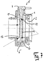
- FIG 5 shows a circumferential sealing edge 9, 10 in the flow direction in front of and behind the adjusting axis 6 in the inner wall 2 of the housing 1, which protrude into the flow channel 3 and against which the seal 4b rests, so that the shut-off flap 4 in its closed position relative to the Housing 1 is sealed.
- the sealing surfaces, which are set by the peripheral sealing edges 9, 10, can be kept small in order to realize low actuating forces or increased accordingly if correspondingly high pressures have to be sealed.
- the adjusting axis 6 is made of metal. It is conceivable to form the adjusting axis 6 and the pivoting lever 7 in one piece.
- figure 7 shows a shut-off valve according to the prior art in one of figure 5 appropriate cut.
- the seal 11 made of soft silicone is inserted into the housing 1 in a peripheral groove 13 .
- a circumferential sealing lip 12 protrudes radially inwards from the seal 11 and is interrupted at the diametral bores in the seal, through which the adjusting axis 6 is guided. Sealing problems can occur at these points.
Landscapes
- Engineering & Computer Science (AREA)
- General Engineering & Computer Science (AREA)
- Mechanical Engineering (AREA)
- Lift Valve (AREA)
- Compressor (AREA)
Description
- Die Erfindung betrifft eine Absperrarmatur mit einem Gehäuse, dessen Innenwandung einen im Querschnitt runden Durchflusskanal ausbildet, und einer im Durchflusskanal angeordneten zylindrischen Absperrklappe, die mittels einer Stelleinrichtung von einer geschlossenen Stellung, in der die Absperrklappe umfangsseitig an mindestens einer in der Innenwandung vorgesehenen umlaufend geschlossenen Dichtkante abgedichtet anliegt, in eine geöffnete Stellung verschwenkbar ist.
- Eine solche Absperrarmatur ist beispielsweise aus der
CN 107355548 A bekannt. Diese Absperrarmatur ist für große Durchmesser und hohe Drücke vorgesehen. Hierzu wird die Absperrklappe aus zwei parallel angeordneten Metallplatten gebildet, die über quer hierzu verlaufende Führungsplatten auf Abstand zueinander gehalten werden. Die Abdichtung zwischen der schweren Abdichtklappe und der Rohrwandung erfolgt über zwei Metallringe. Die Absperrarmatur ist für den Einsatz beispielsweise in der Lebensmittelindustrie nicht geeignet, weil sie viel zu groß und kompliziert aufgebaut ist. - Die
US 2017/0328477 A1 offenbart eine Absperrarmatur mit einem T-förmigen Gehäuse, über die zwei entgegengesetzt verlaufende Wege für das über den Anschluss in die Armatur gelangende Fluid geschaltet werden können. Hierzu ist zentral in der die entgegengesetzten Wege bildenden Leitung eine nicht zylindrische Absperrklappe eingesetzt, die jeweils um 45° in entgegensetzte Richtungen verschwenkbar ist und so die unterschiedlichen Wege freigibt. - Andere Absperrarmaturen sind beispielsweise aus der
US 4,335,748 A , derCN 202493692 U , derDE 100 31 450 A1 und derCN 2018-27394 U bekannt. - Absperrarmaturen mit kleineren Abmessungen sind beispielsweise aus der
DE 195 24 622 A1 oder derDE 2 244 552 A bekannt. - Solche Absperrarmaturen können ein einstückiges Gehäuse aufweisen, in das der Durchflusskanal eingearbeitet ist oder aus einem zweiteiligen Gehäuse bestehen, wobei die beiden Gehäusehälften dann zu einer Einheit verschraubt werden. In den Durchflusskanal wird üblicherweise ein Dichtring eingesetzt, der über die Innenwandung in den Durchflusskanal hineinragt und mit einer umlaufenden Dichtkante versehen ist, sodass die Absperrklappe in der geschlossenen Stellung gegenüber dem Gehäuse abgedichtet ist. Derartige Absperrarmaturen werden üblicherweise in der Lebensmittelindustrie an großen Gebinden für Flüssigkeiten, beispielsweise Flüssigei oder Pizzabelag oder dergleichen verwendet und dienen als Zapfstelle. Die Stelleinrichtung wird üblicherweise von Hand betätigt. Es ist daher gewünscht, dass zur Verschwenkung der Absperrklappe ein niedriges Drehmoment notwendig ist, dabei muss aber eine ausreichende Dichtigkeit gewährleistet sein. Um die Dichtigkeit zu gewährleisten sind zwischen Dichtung und Absperrscheibe entsprechende Übermaße vorgesehen. Kritisch an der Abdichtung sind die Bereiche, in denen die Stelleinrichtung durch die Dichtung hindurchgeführt ist, weil dort die Dichtkante unterbrochen ist. Außerdem ist die Montage bzw. die Herstellung der Absperrarmatur aufwendig. So muss zunächst die Dichtung in das Gehäuse eingesetzt werden, wobei die Abdichtung zum Gehäuse sichergestellt sein muss. Beim Einsetzen der Absperrklappe muss dann sorgfältig gearbeitet werden, um die Dichtung nicht zu beschädigen. Um den Zusammenbau zu vereinfachen ist vielfach vorgesehen, dass das Gehäuse als Spritzgussteil aus Kunststoff ausgebildet wird und um die Dichtung herumgespritzt wird. Das bringt entsprechend hohe Werkzeugkosten mit sich, wobei das Problem der Abdichtung zwischen Absperrklappe und Dichtkante im Bereich der Durchtrittstellen für die Stelleinrichtung nicht beseitigt wird.
- Von dieser Problematik ausgehend soll die gattungsgemäße Absperrarmatur in ihrem Aufbau deutlich vereinfacht werden, sodass sie kostengünstig herstellbar ist, insbesondere in der Lebensmittelindustrie Verwendung finden kann und die Sicherheit der Abdichtung verbessert wird.
- Zur Problemlösung zeichnet sich eine gattungsgemäße Absperrarmatur dadurch aus, dass das Gehäuse und die Absperrklappe aus Kunststoff bestehen und die Absperrklappe zweiteilig ausgebildet ist und einen Kern aufweist, der mit einem elastischen Dichtungsmaterial umgeben ist.
- Durch diese Ausgestaltung wird die Dichtung als separates Bauteil eliminiert. Die Herstellung und die Montage der Absperrarmatur werden dadurch vereinfacht. Durch die in der Innenwandung vorgesehene geschlossene Dichtkante kann die umfangsseitige Abdichtung neben der Durchtrittsstelle für die Stelleinrichtung, vorzugsweise in Strömungsrichtung davor, erfolgen. Die Dichtfläche kann klein gehalten werden, sodass niedrige Stellkräfte notwendig sind, um die Absperrarmatur zu verschließen. Eine solche Absperrarmatur eignet sich besonders gut als Aseptik-Ventil für die Lebensmittelindustrie.
- Vorzugsweise sind in der Innenwandung zwei umlaufende geschlossene Dichtkanten zueinander parallel beabstandet angeordnet. Die Abdichtung kann dann vor und hinter der Durchtrittsstelle der Stelleinrichtung erfolgen.
- Die Stelleinrichtung wird vorzugsweise gebildet durch eine im Gehäuse gelagerte Stellachse, die diametral durch die Absperrklappe geführt und zumindest über eine Bohrung einseitig aus dem Gehäuse herausragt. Diese Bohrung ist dann vorzugsweise zwischen den beiden Kanten angeordnet.
- Die Absperrklappe ist zweiteilig ausgebildet und weist einen Kern auf, der mit dem Dichtungsmaterial umgeben ist. Der Kern besteht aus Kunststoff und kann mit dem Dichtungsmaterial, das ein Elastomer, vorzugsweise Silikon, ist umspritzt werden.
- Der Kern weist vorzugsweise eine zentrale Buchse zur Aufnahme der Stellachse auf, wodurch die Montage der Absperrarmatur vereinfacht wird. Die Absperrscheibe kann dann leicht in den Durchflusskanal eingesetzt werden und die Stellachse wird dann durch das Gehäuse und die zentrale Buchse hindurchgesteckt, sodass die Absperrklappe dann in ihrer Position fixiert ist.
- Mit Hilfe einer Zeichnung soll ein Ausführungsbeispiel der Erfindung nachfolgend näher beschrieben werden. Es zeigen:
- Figur 1 -
- die Vorderansicht einer Absperrarmatur;
- Figur 2 -
- die Seitenansicht der Absperrarmatur nach
Figur 1 ; - Figur 3 -
- eine perspektivische Darstellung der Absperrarmatur;
- Figur 4 -
- eine perspektivische Schnittdarstellung der Absperrarmatur;
- Figur 5 -
- den Schnitt entlang der Linie V-V nach
Figur 1 ; - Figur 6 -
- den Schnitt entlang der Linie VI-VI nach
Figur 1 , - Figur 7 -
- eine Absperrarmatur nach dem Stand der Technik im Schnitt.
- Die Absperrarmatur besteht aus Kunststoff und ist im Spritzguss hergestellt. Sie umfasst das Gehäuse 1, dessen Innenwandung 2 einen im Querschnitt runden Durchflusskanal 3 ausbildet, und der im Durchflusskanal 3 schwenkbar angeordneten zylindrische Absperrklappe 4, die über eine Stelleinrichtung 5 von einer geschlossenen in eine geöffnete Stellung verschwenkbar ist. Die Stelleinrichtung 5 besteht aus der Stellachse 6 und dem mit der Stellachse 6 verbundenen Schwenkhebel 7. Die Absperrklappe 4 besteht aus dem Kern 4a, der mit einem Elastomer, vorzugsweise Silikon umspritzt ist, das die Dichtung 4b ausbildet.
- Die Stellachse 6 ist mit ihrem einen Ende 6' in einem Sackloch im Gehäuse 1 gelagert. Mit ihrem gegenüberliegenden Ende 6" ist sie in einem Sackloch im Schwenkhebel 7 gelagert, der wiederum mit seiner äußeren Umfangsfläche in einer im Gehäuse 1 vorgesehenen Bohrung 8 gelagert ist. Zur Ausbildung einer Buchse, die die Stellachse 6 aufnimmt, ist der Kern 4a durchbohrt.
- Wie
Figur 5 zeigt ist in Strömungsrichtung vor und hinter der Stellachse 6 je eine umlaufende Dichtkante 9, 10 in der Innenwandung 2 des Gehäuses 1 ausgebildet, die in den Durchflusskanal 3 hineinragen und an denen die Dichtung 4b anliegt, sodass die Absperrklappe 4 in ihrer geschlossenen Stellung gegenüber dem Gehäuse 1 abgedichtet ist. Dadurch, dass vor und hinter der Stellachse 6 eine umlaufend geschlossene Abdichtung möglich ist, die nicht von der Stellachse 6 unterbrochen wird, ist die Absperrarmatur sehr funktionssicher. Die Dichtflächen, die durch die umlaufenden Dichtkanten 9, 10 eingestellt werde, können klein gehalten werden, um geringe Stellkräfte zu realisieren oder entsprechend vergrößert werden, wenn entsprechend hohe Drücke abgedichtet werden müssen. - Eine kostengünstige Herstellung der Absperrarmatur wird erreicht, wenn alle Teile aus Kunststoff bestehen. Aus Festigkeitsgründen besteht die Stellachse 6 aus Metall. Denkbar ist es, die Stellachse 6 und den Schwenkhebel 7 einstückig auszubilden.
-
Figur 7 zeigt eine Absperrarmatur nach dem Stand der Technik in einem derFigur 5 entsprechenden Schnitt. Die aus Weichsilikon bestehende Dichtung 11 ist in einer Umfangsnut 13 in das Gehäuse 1 eingesetzt. Nach radial innen steht an der Dichtung 11 eine umlaufende Dichtlippe 12 hervor, die an den diametralen Bohrungen in der Dichtung, durch die die Stellachse 6 hindurchgeführt ist, unterbrochen wird. An diesen Stellen können Dichtungsprobleme auftreten. -
- 1
- Gehäuse
- 2
- Innenwandung
- 3
- Durchflusskanal
- 4
- Absperrklappe
- 4a
- Kern
- 4b
- Dichtung
- 5
- Stelleinrichtung
- 6
- Stellachse
- 6'
- Ende
- 6"
- Ende
- 7
- Schwenkhebel
- 8
- Bohrung
- 9
- Dichtkante
- 10
- Dichtkante
- 11
- Dichtung
- 12
- Dichtlippe
- 13
- Umfangsnut
Claims (8)
- Absperrarmatur mit einem Gehäuse (1), dessen Innenwandung (2) einen im Querschnitt runden Durchflusskanal (3) ausbildet, und einer im Durchflusskanal (3) angeordneten zylindrischen Absperrklappe (4), die mittels einer Stelleinrichtung (5) von einer geschlossenen Stellung, in der die Absperrklappe (4) umfangsseitig an mindestens einer in der Innenwandung (2) vorgesehenen umlaufend geschlossenen Dichtkante (9, 10) abgedichtet anliegt, in eine geöffnete Stellung verschwenkbar ist, dadurch gekennzeichnet, dass das Gehäuse (1) und die Absperrklappe (4) aus Kunststoff bestehen und die Absperrklappe (4) zweiteilig ausgebildet ist und einen Kern (4a) aufweist, der mit einem elastischen Dichtungsmaterial (4b) umgeben ist.
- Absperrarmatur nach Anspruch 1, dadurch gekennzeichnet, dass in der Innenwandung (2) zwei umlaufend geschlossene Dichtkanten (9, 10) zueinander parallel beabstandet angeordnet sind.
- Absperrarmatur nach Anspruch 1 oder 2, dadurch gekennzeichnet, dass die Stelleinrichtung (5) gebildet wird durch eine im Gehäuse (1) gelagerte Stellachse (6), die diametral durch die Absperrklappe (4) geführt ist und zumindest über eine Bohrung (8) einseitig aus dem Gehäuse (2) herausragt.
- Absperrarmatur nach Ansprüchen 2 und 3, dadurch gekennzeichnet, dass die Bohrung (8) zwischen den Dichtkanten (9, 10) angeordnet ist.
- Absperrarmatur nach Anspruch 1, dadurch gekennzeichnet, dass der Kern (4a) eine zentrale Buchse zur Aufnahme der Stellachse (6) aufweist.
- Absperrarmatur nach einem der vorstehenden Ansprüche, dadurch gekennzeichnet, dass der Kunststoff Silikon ist.
- Absperrarmatur nach Anspruch 1, dadurch gekennzeichnet, dass der Kern (4a) mit dem Dichtungsmaterial (4b) umspritzt ist.
- Absperrarmatur nach einem der vorstehenden Ansprüche, dadurch gekennzeichnet, dass das Dichtungsmaterial ein Elastomer, insbesondere Silikon ist.
Priority Applications (3)
| Application Number | Priority Date | Filing Date | Title |
|---|---|---|---|
| EP19169918.0A EP3726106B1 (de) | 2019-04-17 | 2019-04-17 | Absperrarmatur |
| ES19169918T ES2939483T3 (es) | 2019-04-17 | 2019-04-17 | Válvula de cierre |
| PL19169918.0T PL3726106T3 (pl) | 2019-04-17 | 2019-04-17 | Armatura odcinająca |
Applications Claiming Priority (1)
| Application Number | Priority Date | Filing Date | Title |
|---|---|---|---|
| EP19169918.0A EP3726106B1 (de) | 2019-04-17 | 2019-04-17 | Absperrarmatur |
Publications (2)
| Publication Number | Publication Date |
|---|---|
| EP3726106A1 EP3726106A1 (de) | 2020-10-21 |
| EP3726106B1 true EP3726106B1 (de) | 2022-11-16 |
Family
ID=66217987
Family Applications (1)
| Application Number | Title | Priority Date | Filing Date |
|---|---|---|---|
| EP19169918.0A Active EP3726106B1 (de) | 2019-04-17 | 2019-04-17 | Absperrarmatur |
Country Status (3)
| Country | Link |
|---|---|
| EP (1) | EP3726106B1 (de) |
| ES (1) | ES2939483T3 (de) |
| PL (1) | PL3726106T3 (de) |
Family Cites Families (8)
| Publication number | Priority date | Publication date | Assignee | Title |
|---|---|---|---|---|
| DE2244552C3 (de) | 1972-09-11 | 1978-09-21 | Schrupp & Co Gmbh, 5240 Betzdorf | Drosselklappe |
| US4335748A (en) * | 1980-04-14 | 1982-06-22 | Posi-Seal International, Inc. | Bidirectional control valve |
| DE19524622A1 (de) | 1995-07-06 | 1997-01-09 | Ebro Armaturen Gebr Broeer Gmb | Absperrarmatur |
| DE10031450A1 (de) * | 1999-11-02 | 2001-06-07 | Peter Mette | Doppelsitz-Klappventil mit Leckagesicherung |
| CN201827394U (zh) * | 2010-09-20 | 2011-05-11 | 天工阀门集团有限公司 | 合成气制丙烯专用高温高压金属硬密封蝶阀 |
| CN202493692U (zh) * | 2012-02-10 | 2012-10-17 | 鞍山拜尔自控有限公司 | 双板、双座、双向、弹性金属硬密封蝶阀 |
| JP6634572B2 (ja) * | 2016-05-13 | 2020-01-22 | 株式会社テージーケー | バタフライバルブ |
| CN107355548A (zh) * | 2017-08-15 | 2017-11-17 | 王中杰 | 双板双阀座双向金属密封的蝶阀 |
-
2019
- 2019-04-17 ES ES19169918T patent/ES2939483T3/es active Active
- 2019-04-17 EP EP19169918.0A patent/EP3726106B1/de active Active
- 2019-04-17 PL PL19169918.0T patent/PL3726106T3/pl unknown
Also Published As
| Publication number | Publication date |
|---|---|
| PL3726106T3 (pl) | 2023-03-20 |
| EP3726106A1 (de) | 2020-10-21 |
| ES2939483T3 (es) | 2023-04-24 |
Similar Documents
| Publication | Publication Date | Title |
|---|---|---|
| DE2150825B2 (de) | Geräuscharmer Wasserhahn | |
| DE2428516A1 (de) | Mengenregelungshahn | |
| DE2620072A1 (de) | Drosselklappenventil | |
| DE102011005879B4 (de) | Ablassventil | |
| DE10126540A1 (de) | Endoskopabsperrhahn mit Rasteinrichtung | |
| DE4402079B4 (de) | Dreh-Absperrorgan | |
| DE1775077B2 (de) | Eingriff-mischventil | |
| DE2400699A1 (de) | Auseinandernehmbarer hahn | |
| EP0889269B1 (de) | Regelbarer Kugelhahn | |
| DE1500162A1 (de) | Absperrhahn | |
| EP1811211B1 (de) | Armatur zum Absperren oder Regeln eines Mediums | |
| EP3271623A1 (de) | Hubventil mit drehentkopplungseinrichtung | |
| DE2832439A1 (de) | Ringdichtung, insbesondere fuer absperrorgane mit kugelfoermigem absperrkoerper | |
| EP3726106B1 (de) | Absperrarmatur | |
| EP2325533A2 (de) | Ventiloberteil | |
| EP2352938B1 (de) | Scheibenventil mit leckagesicherung | |
| WO2020007528A1 (de) | Ventiloberteil | |
| DE102015200187A1 (de) | Ventilvorrichtung in einem Kraftfahrzeug und Verfahren zur Herstellung | |
| EP3565991A1 (de) | Ventilanordnung | |
| EP1271038B1 (de) | Rohrverschraubung | |
| DE102004005038B3 (de) | Ventilschieber für ein Mehrwegeventil | |
| EP3199851B1 (de) | Absperrarmatur | |
| EP3062001B1 (de) | Ventiloberteil | |
| DE202006005369U1 (de) | Absperrarmatur | |
| EP3591271A1 (de) | Ventiloberteil |
Legal Events
| Date | Code | Title | Description |
|---|---|---|---|
| PUAI | Public reference made under article 153(3) epc to a published international application that has entered the european phase |
Free format text: ORIGINAL CODE: 0009012 |
|
| STAA | Information on the status of an ep patent application or granted ep patent |
Free format text: STATUS: THE APPLICATION HAS BEEN PUBLISHED |
|
| AK | Designated contracting states |
Kind code of ref document: A1 Designated state(s): AL AT BE BG CH CY CZ DE DK EE ES FI FR GB GR HR HU IE IS IT LI LT LU LV MC MK MT NL NO PL PT RO RS SE SI SK SM TR |
|
| AX | Request for extension of the european patent |
Extension state: BA ME |
|
| STAA | Information on the status of an ep patent application or granted ep patent |
Free format text: STATUS: REQUEST FOR EXAMINATION WAS MADE |
|
| 17P | Request for examination filed |
Effective date: 20210416 |
|
| RBV | Designated contracting states (corrected) |
Designated state(s): AL AT BE BG CH CY CZ DE DK EE ES FI FR GB GR HR HU IE IS IT LI LT LU LV MC MK MT NL NO PL PT RO RS SE SI SK SM TR |
|
| GRAP | Despatch of communication of intention to grant a patent |
Free format text: ORIGINAL CODE: EPIDOSNIGR1 |
|
| STAA | Information on the status of an ep patent application or granted ep patent |
Free format text: STATUS: GRANT OF PATENT IS INTENDED |
|
| INTG | Intention to grant announced |
Effective date: 20220602 |
|
| GRAS | Grant fee paid |
Free format text: ORIGINAL CODE: EPIDOSNIGR3 |
|
| GRAA | (expected) grant |
Free format text: ORIGINAL CODE: 0009210 |
|
| STAA | Information on the status of an ep patent application or granted ep patent |
Free format text: STATUS: THE PATENT HAS BEEN GRANTED |
|
| AK | Designated contracting states |
Kind code of ref document: B1 Designated state(s): AL AT BE BG CH CY CZ DE DK EE ES FI FR GB GR HR HU IE IS IT LI LT LU LV MC MK MT NL NO PL PT RO RS SE SI SK SM TR |
|
| REG | Reference to a national code |
Ref country code: GB Ref legal event code: FG4D Free format text: NOT ENGLISH |
|
| REG | Reference to a national code |
Ref country code: CH Ref legal event code: EP |
|
| REG | Reference to a national code |
Ref country code: IE Ref legal event code: FG4D Free format text: LANGUAGE OF EP DOCUMENT: GERMAN |
|
| REG | Reference to a national code |
Ref country code: DE Ref legal event code: R096 Ref document number: 502019006261 Country of ref document: DE |
|
| REG | Reference to a national code |
Ref country code: AT Ref legal event code: REF Ref document number: 1531949 Country of ref document: AT Kind code of ref document: T Effective date: 20221215 |
|
| REG | Reference to a national code |
Ref country code: NL Ref legal event code: FP |
|
| REG | Reference to a national code |
Ref country code: LT Ref legal event code: MG9D |
|
| REG | Reference to a national code |
Ref country code: ES Ref legal event code: FG2A Ref document number: 2939483 Country of ref document: ES Kind code of ref document: T3 Effective date: 20230424 |
|
| PG25 | Lapsed in a contracting state [announced via postgrant information from national office to epo] |
Ref country code: SE Free format text: LAPSE BECAUSE OF FAILURE TO SUBMIT A TRANSLATION OF THE DESCRIPTION OR TO PAY THE FEE WITHIN THE PRESCRIBED TIME-LIMIT Effective date: 20221116 Ref country code: PT Free format text: LAPSE BECAUSE OF FAILURE TO SUBMIT A TRANSLATION OF THE DESCRIPTION OR TO PAY THE FEE WITHIN THE PRESCRIBED TIME-LIMIT Effective date: 20230316 Ref country code: NO Free format text: LAPSE BECAUSE OF FAILURE TO SUBMIT A TRANSLATION OF THE DESCRIPTION OR TO PAY THE FEE WITHIN THE PRESCRIBED TIME-LIMIT Effective date: 20230216 Ref country code: LT Free format text: LAPSE BECAUSE OF FAILURE TO SUBMIT A TRANSLATION OF THE DESCRIPTION OR TO PAY THE FEE WITHIN THE PRESCRIBED TIME-LIMIT Effective date: 20221116 Ref country code: FI Free format text: LAPSE BECAUSE OF FAILURE TO SUBMIT A TRANSLATION OF THE DESCRIPTION OR TO PAY THE FEE WITHIN THE PRESCRIBED TIME-LIMIT Effective date: 20221116 |
|
| PGFP | Annual fee paid to national office [announced via postgrant information from national office to epo] |
Ref country code: FR Payment date: 20230209 Year of fee payment: 5 |
|
| PG25 | Lapsed in a contracting state [announced via postgrant information from national office to epo] |
Ref country code: RS Free format text: LAPSE BECAUSE OF FAILURE TO SUBMIT A TRANSLATION OF THE DESCRIPTION OR TO PAY THE FEE WITHIN THE PRESCRIBED TIME-LIMIT Effective date: 20221116 Ref country code: LV Free format text: LAPSE BECAUSE OF FAILURE TO SUBMIT A TRANSLATION OF THE DESCRIPTION OR TO PAY THE FEE WITHIN THE PRESCRIBED TIME-LIMIT Effective date: 20221116 Ref country code: IS Free format text: LAPSE BECAUSE OF FAILURE TO SUBMIT A TRANSLATION OF THE DESCRIPTION OR TO PAY THE FEE WITHIN THE PRESCRIBED TIME-LIMIT Effective date: 20230316 Ref country code: HR Free format text: LAPSE BECAUSE OF FAILURE TO SUBMIT A TRANSLATION OF THE DESCRIPTION OR TO PAY THE FEE WITHIN THE PRESCRIBED TIME-LIMIT Effective date: 20221116 Ref country code: GR Free format text: LAPSE BECAUSE OF FAILURE TO SUBMIT A TRANSLATION OF THE DESCRIPTION OR TO PAY THE FEE WITHIN THE PRESCRIBED TIME-LIMIT Effective date: 20230217 |
|
| PGFP | Annual fee paid to national office [announced via postgrant information from national office to epo] |
Ref country code: PL Payment date: 20230215 Year of fee payment: 5 |
|
| PG25 | Lapsed in a contracting state [announced via postgrant information from national office to epo] |
Ref country code: SM Free format text: LAPSE BECAUSE OF FAILURE TO SUBMIT A TRANSLATION OF THE DESCRIPTION OR TO PAY THE FEE WITHIN THE PRESCRIBED TIME-LIMIT Effective date: 20221116 Ref country code: RO Free format text: LAPSE BECAUSE OF FAILURE TO SUBMIT A TRANSLATION OF THE DESCRIPTION OR TO PAY THE FEE WITHIN THE PRESCRIBED TIME-LIMIT Effective date: 20221116 Ref country code: EE Free format text: LAPSE BECAUSE OF FAILURE TO SUBMIT A TRANSLATION OF THE DESCRIPTION OR TO PAY THE FEE WITHIN THE PRESCRIBED TIME-LIMIT Effective date: 20221116 Ref country code: DK Free format text: LAPSE BECAUSE OF FAILURE TO SUBMIT A TRANSLATION OF THE DESCRIPTION OR TO PAY THE FEE WITHIN THE PRESCRIBED TIME-LIMIT Effective date: 20221116 Ref country code: CZ Free format text: LAPSE BECAUSE OF FAILURE TO SUBMIT A TRANSLATION OF THE DESCRIPTION OR TO PAY THE FEE WITHIN THE PRESCRIBED TIME-LIMIT Effective date: 20221116 |
|
| PGFP | Annual fee paid to national office [announced via postgrant information from national office to epo] |
Ref country code: IT Payment date: 20230412 Year of fee payment: 5 Ref country code: ES Payment date: 20230504 Year of fee payment: 5 Ref country code: DE Payment date: 20230210 Year of fee payment: 5 Ref country code: CH Payment date: 20230501 Year of fee payment: 5 |
|
| REG | Reference to a national code |
Ref country code: DE Ref legal event code: R097 Ref document number: 502019006261 Country of ref document: DE |
|
| PG25 | Lapsed in a contracting state [announced via postgrant information from national office to epo] |
Ref country code: SK Free format text: LAPSE BECAUSE OF FAILURE TO SUBMIT A TRANSLATION OF THE DESCRIPTION OR TO PAY THE FEE WITHIN THE PRESCRIBED TIME-LIMIT Effective date: 20221116 Ref country code: AL Free format text: LAPSE BECAUSE OF FAILURE TO SUBMIT A TRANSLATION OF THE DESCRIPTION OR TO PAY THE FEE WITHIN THE PRESCRIBED TIME-LIMIT Effective date: 20221116 |
|
| PLBE | No opposition filed within time limit |
Free format text: ORIGINAL CODE: 0009261 |
|
| STAA | Information on the status of an ep patent application or granted ep patent |
Free format text: STATUS: NO OPPOSITION FILED WITHIN TIME LIMIT |
|
| 26N | No opposition filed |
Effective date: 20230817 |
|
| PG25 | Lapsed in a contracting state [announced via postgrant information from national office to epo] |
Ref country code: SI Free format text: LAPSE BECAUSE OF FAILURE TO SUBMIT A TRANSLATION OF THE DESCRIPTION OR TO PAY THE FEE WITHIN THE PRESCRIBED TIME-LIMIT Effective date: 20221116 |
|
| GBPC | Gb: european patent ceased through non-payment of renewal fee |
Effective date: 20230417 |
|
| PG25 | Lapsed in a contracting state [announced via postgrant information from national office to epo] |
Ref country code: LU Free format text: LAPSE BECAUSE OF NON-PAYMENT OF DUE FEES Effective date: 20230417 |
|
| REG | Reference to a national code |
Ref country code: BE Ref legal event code: MM Effective date: 20230430 |
|
| PG25 | Lapsed in a contracting state [announced via postgrant information from national office to epo] |
Ref country code: MC Free format text: LAPSE BECAUSE OF FAILURE TO SUBMIT A TRANSLATION OF THE DESCRIPTION OR TO PAY THE FEE WITHIN THE PRESCRIBED TIME-LIMIT Effective date: 20221116 |
|
| PG25 | Lapsed in a contracting state [announced via postgrant information from national office to epo] |
Ref country code: GB Free format text: LAPSE BECAUSE OF NON-PAYMENT OF DUE FEES Effective date: 20230417 |
|
| PG25 | Lapsed in a contracting state [announced via postgrant information from national office to epo] |
Ref country code: MC Free format text: LAPSE BECAUSE OF FAILURE TO SUBMIT A TRANSLATION OF THE DESCRIPTION OR TO PAY THE FEE WITHIN THE PRESCRIBED TIME-LIMIT Effective date: 20221116 Ref country code: GB Free format text: LAPSE BECAUSE OF NON-PAYMENT OF DUE FEES Effective date: 20230417 |
|
| REG | Reference to a national code |
Ref country code: IE Ref legal event code: MM4A |
|
| PG25 | Lapsed in a contracting state [announced via postgrant information from national office to epo] |
Ref country code: BE Free format text: LAPSE BECAUSE OF NON-PAYMENT OF DUE FEES Effective date: 20230430 |
|
| PG25 | Lapsed in a contracting state [announced via postgrant information from national office to epo] |
Ref country code: IE Free format text: LAPSE BECAUSE OF NON-PAYMENT OF DUE FEES Effective date: 20230417 |
|
| PG25 | Lapsed in a contracting state [announced via postgrant information from national office to epo] |
Ref country code: IE Free format text: LAPSE BECAUSE OF NON-PAYMENT OF DUE FEES Effective date: 20230417 |
|
| PGFP | Annual fee paid to national office [announced via postgrant information from national office to epo] |
Ref country code: NL Payment date: 20240422 Year of fee payment: 6 |