EP3724512B1 - Gehäuse hergestellt in einem arbeitsgang - Google Patents
Gehäuse hergestellt in einem arbeitsgang Download PDFInfo
- Publication number
- EP3724512B1 EP3724512B1 EP18825624.2A EP18825624A EP3724512B1 EP 3724512 B1 EP3724512 B1 EP 3724512B1 EP 18825624 A EP18825624 A EP 18825624A EP 3724512 B1 EP3724512 B1 EP 3724512B1
- Authority
- EP
- European Patent Office
- Prior art keywords
- housing
- ribs
- hub
- sprue
- shaft base
- Prior art date
- Legal status (The legal status is an assumption and is not a legal conclusion. Google has not performed a legal analysis and makes no representation as to the accuracy of the status listed.)
- Active
Links
Images




Classifications
-
- F—MECHANICAL ENGINEERING; LIGHTING; HEATING; WEAPONS; BLASTING
- F04—POSITIVE - DISPLACEMENT MACHINES FOR LIQUIDS; PUMPS FOR LIQUIDS OR ELASTIC FLUIDS
- F04D—NON-POSITIVE-DISPLACEMENT PUMPS
- F04D29/00—Details, component parts, or accessories
- F04D29/26—Rotors specially for elastic fluids
- F04D29/32—Rotors specially for elastic fluids for axial flow pumps
- F04D29/38—Blades
- F04D29/384—Blades characterised by form
-
- B—PERFORMING OPERATIONS; TRANSPORTING
- B29—WORKING OF PLASTICS; WORKING OF SUBSTANCES IN A PLASTIC STATE IN GENERAL
- B29D—PRODUCING PARTICULAR ARTICLES FROM PLASTICS OR FROM SUBSTANCES IN A PLASTIC STATE
- B29D22/00—Producing hollow articles
-
- F—MECHANICAL ENGINEERING; LIGHTING; HEATING; WEAPONS; BLASTING
- F04—POSITIVE - DISPLACEMENT MACHINES FOR LIQUIDS; PUMPS FOR LIQUIDS OR ELASTIC FLUIDS
- F04D—NON-POSITIVE-DISPLACEMENT PUMPS
- F04D17/00—Radial-flow pumps, e.g. centrifugal pumps; Helico-centrifugal pumps
- F04D17/06—Helico-centrifugal pumps
-
- F—MECHANICAL ENGINEERING; LIGHTING; HEATING; WEAPONS; BLASTING
- F04—POSITIVE - DISPLACEMENT MACHINES FOR LIQUIDS; PUMPS FOR LIQUIDS OR ELASTIC FLUIDS
- F04D—NON-POSITIVE-DISPLACEMENT PUMPS
- F04D19/00—Axial-flow pumps
- F04D19/002—Axial flow fans
-
- F—MECHANICAL ENGINEERING; LIGHTING; HEATING; WEAPONS; BLASTING
- F04—POSITIVE - DISPLACEMENT MACHINES FOR LIQUIDS; PUMPS FOR LIQUIDS OR ELASTIC FLUIDS
- F04D—NON-POSITIVE-DISPLACEMENT PUMPS
- F04D29/00—Details, component parts, or accessories
- F04D29/02—Selection of particular materials
- F04D29/023—Selection of particular materials especially adapted for elastic fluid pumps
-
- F—MECHANICAL ENGINEERING; LIGHTING; HEATING; WEAPONS; BLASTING
- F04—POSITIVE - DISPLACEMENT MACHINES FOR LIQUIDS; PUMPS FOR LIQUIDS OR ELASTIC FLUIDS
- F04D—NON-POSITIVE-DISPLACEMENT PUMPS
- F04D29/00—Details, component parts, or accessories
- F04D29/26—Rotors specially for elastic fluids
- F04D29/28—Rotors specially for elastic fluids for centrifugal or helico-centrifugal pumps for radial-flow or helico-centrifugal pumps
- F04D29/281—Rotors specially for elastic fluids for centrifugal or helico-centrifugal pumps for radial-flow or helico-centrifugal pumps for fans or blowers
-
- F—MECHANICAL ENGINEERING; LIGHTING; HEATING; WEAPONS; BLASTING
- F04—POSITIVE - DISPLACEMENT MACHINES FOR LIQUIDS; PUMPS FOR LIQUIDS OR ELASTIC FLUIDS
- F04D—NON-POSITIVE-DISPLACEMENT PUMPS
- F04D29/00—Details, component parts, or accessories
- F04D29/26—Rotors specially for elastic fluids
- F04D29/32—Rotors specially for elastic fluids for axial flow pumps
- F04D29/325—Rotors specially for elastic fluids for axial flow pumps for axial flow fans
-
- F—MECHANICAL ENGINEERING; LIGHTING; HEATING; WEAPONS; BLASTING
- F04—POSITIVE - DISPLACEMENT MACHINES FOR LIQUIDS; PUMPS FOR LIQUIDS OR ELASTIC FLUIDS
- F04D—NON-POSITIVE-DISPLACEMENT PUMPS
- F04D29/00—Details, component parts, or accessories
- F04D29/40—Casings; Connections of working fluid
- F04D29/42—Casings; Connections of working fluid for radial or helico-centrifugal pumps
- F04D29/4206—Casings; Connections of working fluid for radial or helico-centrifugal pumps especially adapted for elastic fluid pumps
- F04D29/4226—Fan casings
-
- F—MECHANICAL ENGINEERING; LIGHTING; HEATING; WEAPONS; BLASTING
- F04—POSITIVE - DISPLACEMENT MACHINES FOR LIQUIDS; PUMPS FOR LIQUIDS OR ELASTIC FLUIDS
- F04D—NON-POSITIVE-DISPLACEMENT PUMPS
- F04D29/00—Details, component parts, or accessories
- F04D29/40—Casings; Connections of working fluid
- F04D29/42—Casings; Connections of working fluid for radial or helico-centrifugal pumps
- F04D29/44—Fluid-guiding means, e.g. diffusers
- F04D29/441—Fluid-guiding means, e.g. diffusers especially adapted for elastic fluid pumps
-
- F—MECHANICAL ENGINEERING; LIGHTING; HEATING; WEAPONS; BLASTING
- F04—POSITIVE - DISPLACEMENT MACHINES FOR LIQUIDS; PUMPS FOR LIQUIDS OR ELASTIC FLUIDS
- F04D—NON-POSITIVE-DISPLACEMENT PUMPS
- F04D29/00—Details, component parts, or accessories
- F04D29/40—Casings; Connections of working fluid
- F04D29/42—Casings; Connections of working fluid for radial or helico-centrifugal pumps
- F04D29/44—Fluid-guiding means, e.g. diffusers
- F04D29/441—Fluid-guiding means, e.g. diffusers especially adapted for elastic fluid pumps
- F04D29/444—Bladed diffusers
-
- F—MECHANICAL ENGINEERING; LIGHTING; HEATING; WEAPONS; BLASTING
- F04—POSITIVE - DISPLACEMENT MACHINES FOR LIQUIDS; PUMPS FOR LIQUIDS OR ELASTIC FLUIDS
- F04D—NON-POSITIVE-DISPLACEMENT PUMPS
- F04D29/00—Details, component parts, or accessories
- F04D29/40—Casings; Connections of working fluid
- F04D29/52—Casings; Connections of working fluid for axial pumps
- F04D29/522—Casings; Connections of working fluid for axial pumps especially adapted for elastic fluid pumps
-
- F—MECHANICAL ENGINEERING; LIGHTING; HEATING; WEAPONS; BLASTING
- F05—INDEXING SCHEMES RELATING TO ENGINES OR PUMPS IN VARIOUS SUBCLASSES OF CLASSES F01-F04
- F05D—INDEXING SCHEME FOR ASPECTS RELATING TO NON-POSITIVE-DISPLACEMENT MACHINES OR ENGINES, GAS-TURBINES OR JET-PROPULSION PLANTS
- F05D2230/00—Manufacture
- F05D2230/20—Manufacture essentially without removing material
-
- F—MECHANICAL ENGINEERING; LIGHTING; HEATING; WEAPONS; BLASTING
- F05—INDEXING SCHEMES RELATING TO ENGINES OR PUMPS IN VARIOUS SUBCLASSES OF CLASSES F01-F04
- F05D—INDEXING SCHEME FOR ASPECTS RELATING TO NON-POSITIVE-DISPLACEMENT MACHINES OR ENGINES, GAS-TURBINES OR JET-PROPULSION PLANTS
- F05D2240/00—Components
- F05D2240/10—Stators
- F05D2240/14—Casings or housings protecting or supporting assemblies within
-
- F—MECHANICAL ENGINEERING; LIGHTING; HEATING; WEAPONS; BLASTING
- F05—INDEXING SCHEMES RELATING TO ENGINES OR PUMPS IN VARIOUS SUBCLASSES OF CLASSES F01-F04
- F05D—INDEXING SCHEME FOR ASPECTS RELATING TO NON-POSITIVE-DISPLACEMENT MACHINES OR ENGINES, GAS-TURBINES OR JET-PROPULSION PLANTS
- F05D2240/00—Components
- F05D2240/20—Rotors
- F05D2240/30—Characteristics of rotor blades, i.e. of any element transforming dynamic fluid energy to or from rotational energy and being attached to a rotor
-
- F—MECHANICAL ENGINEERING; LIGHTING; HEATING; WEAPONS; BLASTING
- F05—INDEXING SCHEMES RELATING TO ENGINES OR PUMPS IN VARIOUS SUBCLASSES OF CLASSES F01-F04
- F05D—INDEXING SCHEME FOR ASPECTS RELATING TO NON-POSITIVE-DISPLACEMENT MACHINES OR ENGINES, GAS-TURBINES OR JET-PROPULSION PLANTS
- F05D2240/00—Components
- F05D2240/20—Rotors
- F05D2240/30—Characteristics of rotor blades, i.e. of any element transforming dynamic fluid energy to or from rotational energy and being attached to a rotor
- F05D2240/303—Characteristics of rotor blades, i.e. of any element transforming dynamic fluid energy to or from rotational energy and being attached to a rotor related to the leading edge of a rotor blade
-
- F—MECHANICAL ENGINEERING; LIGHTING; HEATING; WEAPONS; BLASTING
- F05—INDEXING SCHEMES RELATING TO ENGINES OR PUMPS IN VARIOUS SUBCLASSES OF CLASSES F01-F04
- F05D—INDEXING SCHEME FOR ASPECTS RELATING TO NON-POSITIVE-DISPLACEMENT MACHINES OR ENGINES, GAS-TURBINES OR JET-PROPULSION PLANTS
- F05D2300/00—Materials; Properties thereof
- F05D2300/40—Organic materials
- F05D2300/44—Resins
Definitions
- the invention relates to a housing for a fan which is manufactured in one operation.
- a fan or ventilator contains a number of impeller blades arranged around a shaft. Such impeller blades are subject to high demands. In terms of their dynamic-mechanical properties, the fans must be able to operate at high speeds. This means that tensile stresses caused by centrifugal forces and bending stresses generated by the air flow occur on the propeller blade during operation.
- fan impellers from fiber-reinforced plastic, e.g. from glass-fiber-reinforced polyester or polyamide, using a lamination process.
- the propeller blades are made in several parts, preferably two parts, as lower and upper half shells using hand lamination in external molds. The two half shells are then joined to form a propeller blade, for example by gluing and overlaminating the joint seam to form a hollow chamber.
- Another preferred measure is to thicken the sprue side for the sprue during injection molding.
- a housing for this purpose, the housing having a cover plate with a cylindrical wall and a central receptacle with a hub for supporting a fan with a diagonal fan wheel, wherein a plurality of three-dimensionally curved air guide vanes are arranged around the hub and the air guide vanes are materially connected to the cylindrical wall and for this purpose the housing is manufactured in one work step.
- the housing as a whole has both is designed as a single piece or as a single part.
- one of the work steps is an injection molding process in which the housing is manufactured in one injection molding process from a sprue side (A) to a washboard side (W). It is also advantageous if a material thickening is provided on the sprue side of the housing.
- the air guide vanes are connected with the largest possible radii in the transition to the inner wall of the cylindrical wall.
- the central receptacle of the housing also has a shaft base and on the shaft side, i.e. on the side facing the fan wheel, this is provided with an asymmetrical ribbing, formed from several star-shaped webs or ribs, which also increase the strength of the fan wheel.
- the asymmetrical arrangement of the webs has shown favorable flow behavior in the injection molding tool.
- the plurality of ribs are arranged unevenly in number with respect to an imaginary central dividing line across the housing, diametrically opposite each other on both sides of the imaginary central dividing line, wherein preferably three ribs are provided on a first side (sprue side) and two ribs are provided on the diametrically opposite side (washboard side).
- two window-like openings are provided in the shaft base in areas without ribbing, i.e. between the ribs.
- a cylindrical wall running around the hub is provided on the shaft base and the air guide vanes are connected in one piece and in one part to a connecting section on this wall.
- a preferred embodiment is one in which curved ribs or webs are also provided on the shaft base, which are arranged radially around the hub at least in sections and cross the previously described radially arranged ribs (which are arranged in a star shape), preferably approximately in their middle with respect to their longitudinal extent.
- a further aspect of the present invention relates to the manufacturing method for producing a housing as described above in one work step in the injection molding process in an injection molding tool.
- the Figure 1 shows a perspective view of an embodiment of a housing 10 manufactured in one piece (in one work step) for accommodating a diagonal fan, as shown in the Figure 5 can be recognized.
- the housing 10 has a cover plate 20 provided with an opening 24 and a cylindrical wall 21 extending in an axial direction from the cover plate 20.
- the cover plate also has the function of serving as a flange connection in order to be connected to a fan V, as in the Figure 5 shown, to be brought into an assembly connection.
- the cover plate 20 has flange connectors 26 at the corners.
- the housing 10 has a central receptacle 30 with a hub 31 for supporting a fan having a diagonal fan wheel.
- the hub 31 is connected here as a cylindrically shaped sleeve to the shaft base 32.
- a plurality of three-dimensionally curved air guide vanes S are arranged around the hub 30 and at a distance from it. These air guide vanes S are materially connected to the cylindrical wall 37 of the central receptacle 30.
- the process direction during spraying is well defined from the Figure 4 which is intended to schematically represent one work step in the injection molding process, whereby the housing 10 is produced in an injection molding tool in one injection process via a sprue from a sprue side A to a washboard side W.
- the channel course in the area after the outlet W to the washboard side of the injection molding tool is curved.
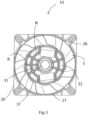
- the Figure 3 provides a view of the view Figure 2
- the central receptacle 30 of the housing 10 has a shaft base 32 and this has an asymmetrical ribbing of ribs R on the shaft side, thus on the side facing the fan wheel.
- two curved (partially circular) ribs R are provided on the shaft base 32, which are arranged at least in sections radially around the hub 31 and cross the radially arranged ribs R and these approximately in the middle of the latter with respect to their longitudinal extent and extend on both sides at the end to the cylindrical wall 37.
- the production is carried out in such a way that a thickening and a pitch jump are provided on the sprue side at sprue A and diametrically opposite (thus on the washboard side W).
- the invention is not limited in its implementation to the preferred embodiments given above. Rather, a number of variants are conceivable which make use of the solution shown in the figures even in fundamentally different embodiments.
Landscapes
- Engineering & Computer Science (AREA)
- Mechanical Engineering (AREA)
- General Engineering & Computer Science (AREA)
- Structures Of Non-Positive Displacement Pumps (AREA)
- Moulds For Moulding Plastics Or The Like (AREA)
Description
- Die Erfindung betrifft ein Gehäuse für einen Ventilator, das in einem Arbeitsgang hergestellt ist.
- In diversen Anwendungen sind hohe Drehzahlen erforderlich, womit sich hohe Anforderungen an die mechanische Festigkeit der Schaufelräder eines Ventilators ergeben.
- Ein Lüfter bzw. Ventilator enthält jeweils eine Mehrzahl von um eine Welle angeordnete Laufradflügel. An solche Laufradflügel sind hohe Anforderungen gestellt. Hinsichtlich ihrer dynamisch-mechanischen Eigenschaften sollen die Ventilatoren im Drehzahlbereich von hohen Drehzahlen arbeiten können. Somit treten am Propellerflügel im Betrieb durch Zentrifugalkräfte verursachte Zugspannungen und durch die Luftförderung erzeugte Biegespannungen auf.
- Es ist bekannt, Ventilatorlaufräder aus faserverstärktem Kunststoff, bsp. aus glasfaserverstärktem Polyester oder Polyamid, im Laminierverfahren herzustellen. Dazu werden die Propollerflügel mehrteilig, vorzugsweise zweiteilig als jeweils untere und obere Halbschalen mittels Handlamination in Aussenformen gefertigt. Die beiden Halbschalen werden danach z. B. unter Ausbildung einer Hohlkammer mittels Kleben und Überlaminieren der Fügenaht zu einem Propellerffügel gefügt.
- Diese Technik weist den Nachteil auf, dass die Wanddicken sowie der Fasergehalt durch die Handlamination nicht genau reproduzierbar sind. Die Folge sind Gewichtsunterschiede zwischen den einzelnen Propollerflügeln, was zu Unwuchten im Propeller führt, die wiederum durch aufwändige Massnahmen beseitigt werden müssen.
- Weitere bekannte Verfahren betreffen das Herstellen mehrere Bauteile, die zu einem Ventilatorrad zusammengefügt werden. Besonders bei komplex geformten Ventilatorrädern ist es üblich diese aus einer Mehrzahl von weniger komplexen Einzelkomponenten zu fertigen und zu einer Baugruppe durch bekannte Montageverfahren zu einem Bauteil zusammen zu fügen. Diese bekannten Maßnahmen zeigen diverse Nachteile (Bauteilanzahl, Montageaufwand, hohe Montagekosten, Werkzeugvielfalt, ...), die es zu vermeiden gilt.
- Druckschriftlicher Stand der Technik im vorliegenden technischen Gebiet ist in den Dokumenten
US 2006/039 784 A1 ,WO 2015/075 103 A1 ,WO 2017/026 143 A1 ,DE 10 2012 000 376 A1 ,US 2014/186 198 A1 undEP 1 619 393 A2 offenbart. - Es ist die Aufgabe der vorliegenden Erfindung, eine Lösung zur Herstellung eines Gehäuses eines Ventilators bereitzustellen, die kostengünstig realisierbar ist und mit der sich verbesserte mechanische Eigenschaften erzielen lassen. Diese Aufgabe wird durch folgende Maßnahmen gelöst, die bevorzugt auch kummulativ kombiniert werden können.
- Eine erste Maßnahme ist die Lösung die Konstruktion des Gehäuses für den Ventilator so zu gestalten, dass sich das Gehäuse in einem einzigen Arbeitsschritt, nämlich einem Spritzgussverfahren einstückig herstellen lässt.
- Eine weitere bevorzugte Maßnahme ist darin zu sehen, die Angusseite für den Anguss beim Spritzguss verdickt auszuführen.
- Eine weitere konstruktive Verbesserung wird darin gesehen, dass die Leitschaufels mit möglichst großen Radien im Übergang an der Innenscheibe oder Bodenscheiben verbunden sind.
- Erfindungsgemäß wird hierzu ein Gehäuse vorgeschlagen, wobei das Gehäuse eine Deckscheibe mit einer zylindrischen Wand und eine zentrale Aufnahme mit einer Nabe zur Lagerung eines Ventilators mit einem Diagonal-ventilatorrad aufweist, wobei um die Nabe mehrere dreidimensional gekrümmte Luftleitsschaufeln angeordnet sind und die Luftleitsschaufeln materialschlüssig mit der zylindrischen Wand verbunden sind und hierzu das Gehäuse in einem Arbeitsschritt hergestellt ist.
- Besonders bevorzugt ist es, wenn das Gehäuse dabei insgesamt sowohl einstückig als auch einteilig ausgebildet ist.
- Weiter vorteilhaft ist es, wenn der eine Arbeitsschritt zur ein Spritzgussverfahren darstellt, bei dem von einer Angussseite (A) zu einer Waschbrettseite (W) das Gehäuse in einem Spritzvorgang in einem Spritzgusswerkzeug hergestellt wird. Weiter vorteilhaft ist es dabei, wenn angusseitig am Gehäuse eine Materialverdickung vorgesehen ist.
- In einer vorteilhaften Ausführungsform der Erfindung ist vorgesehen, dass die Luftleitschaufeln mit möglichst großen Radien im Übergang an der Innenwand der zylindrischen Wand verbunden sind.
- Die zentrale Aufnahme des Gehäuses besitzt erfindungsgemäß ferner einen Schaftboden und an der schaftseitig, somit an der zum Ventilatorrad zugewandten Seite ist dieser mit einer unsymmetrisch ausgeführten Rippung versehen, ausgebildet aus mehreren sternförmig angeordneten Stegen oder Rippen, die auch die Festigkeit des Ventilatorrads erhöhen. Durch die asymmetrische Anordnung der Stege hat sich ein günstiges Fließverhalten im Spritzgusswerkzeug gezeigt.
- In einer weiteren vorteilhaften Ausführungsform der Erfindung ist vorgesehen, dass die mehren Rippen in ihrer Anzahl ungleichmäßig gegenüber einer gedachten mittleren Trennlinie quer durch das Gehäuse diametral gegenüberliegend auf beiden Seiten der gedachten mittleren Trennlinie angeordnet sind, wobei bevorzugt auf einer ersten Seite (angussseitig) drei Rippen und auf der diametral gegenüberliegenden Seite (waschbrettseitig) zwei Rippen vorgesehen sind.
- Mit Vorteil erfolgt die Herstellung so, dass angussseitig am Anguss und diametral gegenüberliegend (somit auf der Waschbrettseite W) einmal eine Verdickung und einmal ein Teilungssprung vorgesehen sind.
- Ferner ist mit Vorteil vorgesehen, dass im Schaftboden zwei fensterartige Öffnungen in Bereichen ohne Rippung vorgesehen sind, d. h. zwischen den Rippen.
- In einer weiteren vorteilhaften Ausführungsform der Erfindung ist vorgesehen, dass am Schaftboden eine zylindrische, um die Nabe herum verlaufende Wandung vorgesehen ist und die Luftleitschaufeln mit einem Verbindungsabschnitt an dieser Wandung einstückig und einteilig verbunden sind.
- Bevorzugt ist dabei eine Ausgestaltung, bei der am Schaftboden ferner gebogene Rippen oder Stege vorgesehen sind, die zumindest abschnittsweise radial um die Nabe herum angeordnet sind und die zuvor beschriebenen radial angeordneten Rippen (die sternförmig angeordnet sind), vorzugsweise in etwa in deren Mitte bezogen auf deren Längserstreckung kreuzen.
- Ein weiterer Aspekt der vorliegenden Erfindung betrifft das Herstellverfahren zum Herstellen eines wie zuvor beschriebenen Gehäuses in einem Arbeitsschritt im Spritzgussverfahren in einem Spritzgusswerkzeug.
- Andere vorteilhafte Weiterbildungen der Erfindung sind in den Unteransprüchen gekennzeichnet bzw. werden nachstehend zusammen mit der Beschreibung der bevorzugten Ausführung der Erfindung anhand der Figuren näher dargestellt.
- Es zeigen:
- Fig. 1
- eine perspektivische Ansicht eines Ausführungsbeispiels eines (in einem Arbeitsschritt) einstückig hergestellten Gehäuses zur Aufnahme eines Diagonalventilators,
- Fig. 2
- eine perspektivische Ansicht des Ausführungsbeispiels eines (in einem Arbeitsschritt) einstückig hergestellten Gehäuses gemäß
Figur 1 von der gegenüberliegenden Perspektive, - Fig. 3
- eine Aufsicht auf die Ansicht aus
Figur 2 , - Fig. 4
- eine schematische Ansicht des Spritzgussverlaufes von der Angussseite bis zur Teilung an der Waschbrettseite und
- Fig. 5
- eine perspektivische Ansicht des Gehäuses 10 mit einem eingesetzten Ventilator.
- Im Folgenden wird die Erfindung mit Bezug auf die
Figuren 1 bis 5 näher erläutert, wobei gleiche Bezugszeichen gleiche funktionale und/oder strukturelle Merkmale darstellen. - Die
Figur 1 zeigt eine perspektivische Ansicht eines Ausführungsbeispiels eines (in einem Arbeitsschritt) einstückig hergestellten Gehäuses 10 zur Aufnahme eines Diagonalventilators, wie dies in derFigur 5 zu erkennen ist. - Das Gehäuse 10 besitzt eine mit einer Öffnung 24 versehene Deckscheibe 20 mit einer zylindrischen Wand 21, die sich in einer Axialrichtung von der Deckscheibe 20 erstreckt. Die Deckscheibe hat hier ferner die Funktion als Flanschverbindung zu dienen, um mit einem Ventilator V, wie in der
Figur 5 gezeigt, in eine Montageverbindung gebracht zu werden. Hierzu besitzt die Deckscheibe 20 an den Ecken Flanschverbinder 26. - Ferner besitzt das Gehäuse 10 eine zentrale Aufnahme 30 mit einer Nabe 31 zur Lagerung eines Ventilators, der ein Diagonalventilatorrad aufweist. Die Nabe 31 ist hier als zylindrische geformte Hülse am Schaftboden 32 verbunden.
- Um die Nabe 30 herum und beabstandet zu dieser sind mehrere dreidimensional gekrümmte Luftleitschaufeln S angeordnet. Diese Luftleitschaufeln S sind materialschlüssig mit der zylindrischen Wand 37 der zentralen Aufnahme 30 verbunden.
- Die Prozessrichtung beim Spritzen ist gut aus der
Figur 4 ersichtlich, der schematisch den einen Arbeitsschritt im Spritzgussverfahren darstellen soll, wobei über einen Anguss von einer Angussseite A zu einer Waschbrettseite W das Gehäuse 10 in einem Spritzvorgang in einem Spritzgusswerkzeug hergestellt wird. Der Kanalverlauf im Bereich nach dem Abgang W zur Waschbrettseite des Spritzgusswerkzeugs ist gekrümmt ausgebildet. - Im Bereich des Anschlusses des Angusses an der Angussseite A findet sich somit angusseitig am Gehäuse 10 eine Materialverdickung 12, wie diese schematisch in der
Figur 2 angedeutet ist. - Die
Figur 3 stellt eine Aufsicht auf die Ansicht ausFigur 2 dar. Die zentrale Aufnahme 30 des Gehäuses 10 besitzt einen Schaftboden 32 ausbildet und dieser besitzt schaftseitig, somit an der zum Ventilatorrad zugewandten Seite eine asymmetrisch ausgeführte Rippung aus Rippen R. - Es sind in dieser Ausführung mehrere (hier 5) sternförmig angeordneten Stege bzw. Rippen R vorgesehen. Diese mehren Rippen R sind in ihrer Position ungleichmäßig gegenüber einer gedachten mittleren Trennlinie ausgerichtet. Im Schaftboden 32 sind ferner zwei fensterartige Öffnungen in Bereichen ohne Rippung vorgesehen. Diese sind ebenfalls asymmetrisch gegenüber der Nabe 31 orientiert.
- Am Schaftboden 32 sind ferner zwei gebogene (teilkreisförmige) Rippen R vorgesehen, die zumindest abschnittsweise radial um die Nabe 31 herum angeordnet sind und die radial angeordneten Rippen R und diese in etwa in deren Mitte bezogen auf deren Längserstreckung kreuzen und sich jeweils beidseitig endseitig bis zur zylindrischen Wandung 37 erstrecken.
- Die Herstellung ist so ausgeführt, dass angussseitig am Anguss A und diametral gegenüberliegend (somit auf der Waschbrettseite W) einmal eine Verdickung und einmal ein Teilungssprung vorgesehen sind.
- Die Erfindung beschränkt sich in ihrer Ausführung nicht auf die vorstehend angegebenen bevorzugten Ausführungsbeispiele. Vielmehr ist eine Anzahl von Varianten denkbar, welche von der dargestellten Lösung gemäß den Figuren auch bei grundsätzlich anders gearteten Ausführungen Gebrauch macht.
Claims (11)
- Gehäuse (10), wobei das Gehäuse eine Deckscheibe (20) mit einer zylindrischen Wand (21) und eine zentrale Aufnahme (30) mit einer Nabe (31) zur Lagerung eines Ventilators mit einem Diagonal-Ventilatorrad aufweist, wobei um die Nabe (31) mehrere dreidimensional gekrümmte Luftleitschaufeln (S) angeordnet sind, wobei die Luftleitschaufeln (S) materialschlüssig mit der zylindrischen Wand (21) verbunden sind und hierzu das Gehäuse (10) in einem Arbeitsschritt hergestellt ist und wobei die zentrale Aufnahme (30) des Gehäuses einen Schaftboden (32) ausbildet, dadurch gekennzeichnet, dass der Schaftboden (31) schaftseitig, somit an der zum Ventilatorrad zugewandten Seite, mit einer unsymmetrisch ausgeführten Rippung versehen ist, ausgebildet aus sternförmig angeordneten mehreren Stegen oder Rippen (R).
- Gehäuse (10) nach Anspruch 1, dadurch gekennzeichnet, dass dieses sowohl einstückig als auch einteilig ausgebildet ist.
- Gehäuse (10) nach Anspruch 1 oder 2, dadurch gekennzeichnet, dass der eine Arbeitsschritt ein Spritzgussverfahren darstellt, bei dem von einer Angussseite (A) zu einer Waschbrettseite (W) das Gehäuse (10) in einem Spritzvorgang in einem Spritzgusswerkzeug hergestellt wird.
- Gehäuse (10) nach Anspruch 3, dadurch gekennzeichnet, dass angussseitig am Gehäuse (10) eine Materialverdickung (12) vorgesehen ist.
- Gehäuse (10) nach einem der vorhergehenden Ansprüche 3 oder 4, dadurch gekennzeichnet, dass die Herstellung so erfolgt, dass angussseitig am Anguss (A) und diametral gegenüberliegend auf der Waschbrettseite (W) einmal eine Verdickung und einmal ein Teilungssprung vorgesehen ist.
- Gehäuse (10) nach einem der vorhergehenden Ansprüche, dadurch gekennzeichnet, dass die Luftleitschaufeln (S) mit Radien im Übergang an der Innenwand der zylindrischen Wand (21) verbunden sind.
- Gehäuse (10) nach einem der vorhergehenden Ansprüche, dadurch gekennzeichnet, dass die mehren Rippen (R) in ihrer Anzahl ungleichmäßig gegenüber einer gedachten mittleren Trennlinie durch das Gehäuse (10) diametral gegenüberliegend auf beiden Seiten der gedachten mittleren Trennlinie angeordnet sind, wobei bevorzugt auf einer ersten Seite drei Rippen (R) und auf der diametral gegenüberliegenden Seite zwei Rippen (R) vorgesehen sind.
- Gehäuse (10) nach einem der vorhergehenden Ansprüche, dadurch gekennzeichnet, dass im Schaftboden (32) zwei fensterartige Öffnungen in Bereichen ohne Rippung vorgesehen sind.
- Gehäuse (10) nach einem der vorhergehenden Ansprüche, dadurch gekennzeichnet, dass am Schaftboden (32) eine zylindrische, um die Nabe (31) herum verlaufende Wandung (37) vorgesehen ist und die Luftleitschaufeln (S) mit einem Verbindungsabschnitt an der Wandung (37) einstückig verbunden sind.
- Gehäuse (10) nach einem der vorhergehenden Ansprüche, dadurch gekennzeichnet, dass am Schaftboden (32) gebogene Rippen (R) vorgesehen sind, die zumindest abschnittsweise radial um die Nabe (31) herum angeordnet sind und die radial angeordneten Rippen (R), vorzugsweise in etwa in deren Mitte bezogen auf deren Längserstreckung kreuzen.
- Herstellverfahren zum Herstellen eines Gehäuses (10) nach einem der Ansprüche 1 bis 10, dadurch gekennzeichnet, dass das Gehäuse (10) in einem Arbeitsschritt im Spritzgussverfahren in einem Spritzgusswerkzeug hergestellt wurde.
Applications Claiming Priority (3)
| Application Number | Priority Date | Filing Date | Title |
|---|---|---|---|
| DE102017011504 | 2017-12-13 | ||
| DE102017011503 | 2017-12-13 | ||
| PCT/EP2018/084811 WO2019115717A1 (de) | 2017-12-13 | 2018-12-13 | Gehäuse hergestellt in einem arbeitsgang |
Publications (2)
| Publication Number | Publication Date |
|---|---|
| EP3724512A1 EP3724512A1 (de) | 2020-10-21 |
| EP3724512B1 true EP3724512B1 (de) | 2024-10-23 |
Family
ID=64755539
Family Applications (2)
| Application Number | Title | Priority Date | Filing Date |
|---|---|---|---|
| EP18825624.2A Active EP3724512B1 (de) | 2017-12-13 | 2018-12-13 | Gehäuse hergestellt in einem arbeitsgang |
| EP18826241.4A Active EP3724511B1 (de) | 2017-12-13 | 2018-12-13 | Diagonalventilatorrad mit erhöhter festigkeit |
Family Applications After (1)
| Application Number | Title | Priority Date | Filing Date |
|---|---|---|---|
| EP18826241.4A Active EP3724511B1 (de) | 2017-12-13 | 2018-12-13 | Diagonalventilatorrad mit erhöhter festigkeit |
Country Status (5)
| Country | Link |
|---|---|
| US (2) | US11542954B2 (de) |
| EP (2) | EP3724512B1 (de) |
| KR (1) | KR102630978B1 (de) |
| CN (2) | CN111183293B (de) |
| WO (2) | WO2019115703A1 (de) |
Families Citing this family (4)
| Publication number | Priority date | Publication date | Assignee | Title |
|---|---|---|---|---|
| USD949315S1 (en) * | 2016-06-24 | 2022-04-19 | Ebm-Papst Mulfingen Gmbh & Co. Kg | Vane damper with trailing edge |
| US12584498B2 (en) | 2021-07-29 | 2026-03-24 | Delta Electronics, Inc. | Fan |
| US12480525B2 (en) | 2023-07-12 | 2025-11-25 | Delta Electronics, Inc. | Impeller and diagonal fan including the same |
| US12473926B1 (en) | 2024-08-14 | 2025-11-18 | Morrison Products, Inc. | Impellers and manufacturing methods thereof |
Citations (2)
| Publication number | Priority date | Publication date | Assignee | Title |
|---|---|---|---|---|
| EP1619393A2 (de) * | 2004-07-21 | 2006-01-25 | Delta Electronics, Inc. | Lüftereinheit und ihr Gehäuse |
| US20140186198A1 (en) * | 2012-12-27 | 2014-07-03 | Minebea Co., Ltd. | Axial fan |
Family Cites Families (23)
| Publication number | Priority date | Publication date | Assignee | Title |
|---|---|---|---|---|
| JPS5949437B2 (ja) | 1977-01-28 | 1984-12-03 | 川崎重工業株式会社 | 斜流送風機の羽根車 |
| US4874293A (en) * | 1988-11-08 | 1989-10-17 | Gutzwiller H Leslie | Modified centrifugal airfoil fan wheel |
| TWI288210B (en) * | 2004-08-18 | 2007-10-11 | Delta Electronics Inc | Heat-dissipating fan and its housing |
| CN100504077C (zh) * | 2004-09-06 | 2009-06-24 | 台达电子工业股份有限公司 | 散热风扇及其扇框座 |
| DE102010034406A1 (de) * | 2009-08-17 | 2011-02-24 | Ebm-Papst St. Georgen Gmbh & Co. Kg | Lüfter |
| DE202009014212U1 (de) | 2009-10-21 | 2011-03-03 | Ebm-Papst Mulfingen Gmbh & Co. Kg | Luftleitelement für einen Axialventilator |
| CN102207106A (zh) * | 2010-03-31 | 2011-10-05 | 鸿富锦精密工业(深圳)有限公司 | 风扇整流架 |
| CN201786754U (zh) * | 2010-08-05 | 2011-04-06 | 东莞市瑞翔模具科技有限公司 | 一种散热风扇的扇框 |
| DE102011015784A1 (de) | 2010-08-12 | 2012-02-16 | Ziehl-Abegg Ag | Ventilator |
| DE202010016820U1 (de) | 2010-12-21 | 2012-03-26 | Ebm-Papst Mulfingen Gmbh & Co. Kg | Diffusor für einen Ventilator sowie Ventilatoranordnung mit einem derartigen Diffusor |
| DE102012000376B4 (de) * | 2012-01-12 | 2013-08-14 | Ebm-Papst St. Georgen Gmbh & Co. Kg | Axial- oder Diagonalventilator |
| CN203175980U (zh) | 2013-04-03 | 2013-09-04 | 宁波朗迪叶轮机械有限公司 | 斜流离心叶轮 |
| US10060442B2 (en) | 2013-10-24 | 2018-08-28 | Dyna-Tech Sales Corporation | Mixed flow fan assembly |
| DE202013105242U1 (de) | 2013-11-19 | 2015-02-20 | Ebm-Papst St. Georgen Gmbh & Co. Kg | Lüftereinheit mit einem Lüftergehäuse |
| DE102013112922A1 (de) * | 2013-11-22 | 2015-05-28 | Ebm-Papst St. Georgen Gmbh & Co. Kg | Diagonal- oder Axiallüfter |
| JP6217347B2 (ja) * | 2013-11-28 | 2017-10-25 | 株式会社デンソー | 送風機 |
| DE102013114609A1 (de) * | 2013-12-20 | 2015-06-25 | Ebm-Papst Mulfingen Gmbh & Co. Kg | Radial-Laufrad für einen Trommellüfter und Lüftereinheit mit einem derartigen Radial-Laufrad |
| KR102020459B1 (ko) * | 2013-12-31 | 2019-09-11 | 한온시스템 주식회사 | 팬 및 쉬라우드 조립체 |
| DE102014006756A1 (de) * | 2014-05-05 | 2015-11-05 | Ziehl-Abegg Se | Laufrad für Diagonal- oder Radialventilatoren, Spritzgusswerkzeug zur Herstellung eines solchen Laufrades sowie Gerät mit einem solchen Laufrad |
| KR102289384B1 (ko) | 2014-12-18 | 2021-08-13 | 삼성전자주식회사 | 원심팬 어셈블리 |
| DE102015207800A1 (de) * | 2015-04-28 | 2016-11-03 | Ziehl-Abegg Se | Diagonal- oder Radialventilator, Leiteinrichtung für einen solchen Ventilator und System mit einem solchen Ventilator oder mit mehreren solcher Ventilatoren |
| CN107923413B (zh) * | 2015-08-10 | 2020-12-01 | 三菱电机株式会社 | 送风机以及空气调节装置 |
| DE102015118387A1 (de) | 2015-10-28 | 2017-05-04 | Ebm-Papst Mulfingen Gmbh & Co. Kg | Ventilatorrad und Ventilator |
-
2018
- 2018-12-13 EP EP18825624.2A patent/EP3724512B1/de active Active
- 2018-12-13 US US16/772,362 patent/US11542954B2/en active Active
- 2018-12-13 KR KR1020207010562A patent/KR102630978B1/ko active Active
- 2018-12-13 CN CN201880064513.5A patent/CN111183293B/zh not_active Expired - Fee Related
- 2018-12-13 CN CN201880078441.XA patent/CN111433463B/zh active Active
- 2018-12-13 US US16/772,327 patent/US11732728B2/en active Active
- 2018-12-13 EP EP18826241.4A patent/EP3724511B1/de active Active
- 2018-12-13 WO PCT/EP2018/084780 patent/WO2019115703A1/de not_active Ceased
- 2018-12-13 WO PCT/EP2018/084811 patent/WO2019115717A1/de not_active Ceased
Patent Citations (2)
| Publication number | Priority date | Publication date | Assignee | Title |
|---|---|---|---|---|
| EP1619393A2 (de) * | 2004-07-21 | 2006-01-25 | Delta Electronics, Inc. | Lüftereinheit und ihr Gehäuse |
| US20140186198A1 (en) * | 2012-12-27 | 2014-07-03 | Minebea Co., Ltd. | Axial fan |
Also Published As
| Publication number | Publication date |
|---|---|
| KR20200096207A (ko) | 2020-08-11 |
| US20210364011A1 (en) | 2021-11-25 |
| US20210381524A1 (en) | 2021-12-09 |
| KR102630978B1 (ko) | 2024-01-30 |
| US11732728B2 (en) | 2023-08-22 |
| CN111433463A (zh) | 2020-07-17 |
| EP3724511A1 (de) | 2020-10-21 |
| EP3724511B1 (de) | 2023-03-22 |
| CN111183293B (zh) | 2022-02-22 |
| CN111183293A (zh) | 2020-05-19 |
| US11542954B2 (en) | 2023-01-03 |
| EP3724512A1 (de) | 2020-10-21 |
| CN111433463B (zh) | 2022-02-01 |
| WO2019115717A1 (de) | 2019-06-20 |
| WO2019115703A1 (de) | 2019-06-20 |
Similar Documents
| Publication | Publication Date | Title |
|---|---|---|
| DE4136293B4 (de) | Laufrad für ein Gebläse, insbesondere Radialgebläse | |
| EP2677174B1 (de) | Lüfterrad sowie Elektromotor | |
| EP1712800B1 (de) | Lüfterrad | |
| DE102008056459A1 (de) | Diagonallüfter | |
| EP1649575A1 (de) | Elektrische maschine mit läuferkühlung und entsprechendes kühlungsverfahren | |
| EP3988797B1 (de) | Axialventilator mit geräuschreduzierenden lüfterradschaufeln, die bohrungen aufweisen | |
| EP3156591A1 (de) | Turbinenlaufrad für eine radialturbine | |
| WO2019115717A1 (de) | Gehäuse hergestellt in einem arbeitsgang | |
| CH497641A (de) | Verfahren zur Herstellung eines Schaufelkranzes für Strömungsmaschinen | |
| DE102016112521A1 (de) | Laufrad für einen Abgasturbolader, Abgasturbolader und Verfahren zum Auswuchten eines Laufzeugs für einen Abgasturbolader | |
| WO2021115806A1 (de) | Lüfterrad für einen rotor und elektrische maschine | |
| EP3367541B1 (de) | Rotor eines elektromotors | |
| DE102009004813B4 (de) | Faserverstärkte Kunststoffplatte mit laminiertem Buchseneinsatz | |
| DE102004031270A1 (de) | Niederdruckventilator mit Y-förmigen Rotorblättern | |
| DE102018132079A1 (de) | Diagonalventilatorrad hergestellt in einem Arbeitsgang | |
| EP4274062A1 (de) | Rotor für einen elektromotor und verfahren zur herstellung | |
| WO2016198260A1 (de) | Vakuumpumpen-rotor | |
| DE102013015835A1 (de) | Lüfter | |
| EP3765749B1 (de) | Elektrische antriebsmaschine für einen verdichter und/oder eine turbine | |
| DE102010029779B4 (de) | Lüfter, Elektromotor und Werkzeugmaschine | |
| WO2010052074A1 (de) | Diagonallüfter | |
| DE102013209475B4 (de) | Verfahren und Werkzeug zur Herstellung einer mehrere Rotorschaufeln aufweisenden Rotorscheibe sowie Rotorscheibe | |
| EP3486494B1 (de) | Radialgebläsegehäuse und radialgebläse | |
| DE102007037012B4 (de) | Gebläseeinheit und handgetragenes Blasgerät | |
| DE102013104534A1 (de) | Laufrad sowie Segment zu dessen Herstellung und Herstellungsverfahren für das Laufrad |
Legal Events
| Date | Code | Title | Description |
|---|---|---|---|
| STAA | Information on the status of an ep patent application or granted ep patent |
Free format text: STATUS: UNKNOWN |
|
| STAA | Information on the status of an ep patent application or granted ep patent |
Free format text: STATUS: THE INTERNATIONAL PUBLICATION HAS BEEN MADE |
|
| PUAI | Public reference made under article 153(3) epc to a published international application that has entered the european phase |
Free format text: ORIGINAL CODE: 0009012 |
|
| STAA | Information on the status of an ep patent application or granted ep patent |
Free format text: STATUS: REQUEST FOR EXAMINATION WAS MADE |
|
| 17P | Request for examination filed |
Effective date: 20200302 |
|
| AK | Designated contracting states |
Kind code of ref document: A1 Designated state(s): AL AT BE BG CH CY CZ DE DK EE ES FI FR GB GR HR HU IE IS IT LI LT LU LV MC MK MT NL NO PL PT RO RS SE SI SK SM TR |
|
| AX | Request for extension of the european patent |
Extension state: BA ME |
|
| RIN1 | Information on inventor provided before grant (corrected) |
Inventor name: USSELMANN, EUGEN Inventor name: LAUFER, WOLFGANG Inventor name: HAAS, WERNER Inventor name: SIEGER, TOBIAS Inventor name: GEBERT, DANIEL |
|
| DAV | Request for validation of the european patent (deleted) | ||
| DAX | Request for extension of the european patent (deleted) | ||
| STAA | Information on the status of an ep patent application or granted ep patent |
Free format text: STATUS: EXAMINATION IS IN PROGRESS |
|
| 17Q | First examination report despatched |
Effective date: 20220930 |
|
| GRAP | Despatch of communication of intention to grant a patent |
Free format text: ORIGINAL CODE: EPIDOSNIGR1 |
|
| STAA | Information on the status of an ep patent application or granted ep patent |
Free format text: STATUS: GRANT OF PATENT IS INTENDED |
|
| INTG | Intention to grant announced |
Effective date: 20240523 |
|
| GRAS | Grant fee paid |
Free format text: ORIGINAL CODE: EPIDOSNIGR3 |
|
| GRAA | (expected) grant |
Free format text: ORIGINAL CODE: 0009210 |
|
| STAA | Information on the status of an ep patent application or granted ep patent |
Free format text: STATUS: THE PATENT HAS BEEN GRANTED |
|
| P01 | Opt-out of the competence of the unified patent court (upc) registered |
Free format text: CASE NUMBER: APP_48663/2024 Effective date: 20240826 |
|
| AK | Designated contracting states |
Kind code of ref document: B1 Designated state(s): AL AT BE BG CH CY CZ DE DK EE ES FI FR GB GR HR HU IE IS IT LI LT LU LV MC MK MT NL NO PL PT RO RS SE SI SK SM TR |
|
| REG | Reference to a national code |
Ref country code: GB Ref legal event code: FG4D Free format text: NOT ENGLISH |
|
| REG | Reference to a national code |
Ref country code: CH Ref legal event code: EP |
|
| REG | Reference to a national code |
Ref country code: DE Ref legal event code: R096 Ref document number: 502018015260 Country of ref document: DE |
|
| REG | Reference to a national code |
Ref country code: IE Ref legal event code: FG4D Free format text: LANGUAGE OF EP DOCUMENT: GERMAN |
|
| REG | Reference to a national code |
Ref country code: LT Ref legal event code: MG9D |
|
| REG | Reference to a national code |
Ref country code: NL Ref legal event code: MP Effective date: 20241023 |
|
| PG25 | Lapsed in a contracting state [announced via postgrant information from national office to epo] |
Ref country code: NL Free format text: LAPSE BECAUSE OF FAILURE TO SUBMIT A TRANSLATION OF THE DESCRIPTION OR TO PAY THE FEE WITHIN THE PRESCRIBED TIME-LIMIT Effective date: 20241023 |
|
| PG25 | Lapsed in a contracting state [announced via postgrant information from national office to epo] |
Ref country code: NL Free format text: LAPSE BECAUSE OF FAILURE TO SUBMIT A TRANSLATION OF THE DESCRIPTION OR TO PAY THE FEE WITHIN THE PRESCRIBED TIME-LIMIT Effective date: 20241023 |
|
| PG25 | Lapsed in a contracting state [announced via postgrant information from national office to epo] |
Ref country code: IS Free format text: LAPSE BECAUSE OF FAILURE TO SUBMIT A TRANSLATION OF THE DESCRIPTION OR TO PAY THE FEE WITHIN THE PRESCRIBED TIME-LIMIT Effective date: 20250223 Ref country code: PT Free format text: LAPSE BECAUSE OF FAILURE TO SUBMIT A TRANSLATION OF THE DESCRIPTION OR TO PAY THE FEE WITHIN THE PRESCRIBED TIME-LIMIT Effective date: 20250224 Ref country code: HR Free format text: LAPSE BECAUSE OF FAILURE TO SUBMIT A TRANSLATION OF THE DESCRIPTION OR TO PAY THE FEE WITHIN THE PRESCRIBED TIME-LIMIT Effective date: 20241023 |
|
| PG25 | Lapsed in a contracting state [announced via postgrant information from national office to epo] |
Ref country code: FI Free format text: LAPSE BECAUSE OF FAILURE TO SUBMIT A TRANSLATION OF THE DESCRIPTION OR TO PAY THE FEE WITHIN THE PRESCRIBED TIME-LIMIT Effective date: 20241023 |
|
| PG25 | Lapsed in a contracting state [announced via postgrant information from national office to epo] |
Ref country code: BG Free format text: LAPSE BECAUSE OF FAILURE TO SUBMIT A TRANSLATION OF THE DESCRIPTION OR TO PAY THE FEE WITHIN THE PRESCRIBED TIME-LIMIT Effective date: 20241023 |
|
| PG25 | Lapsed in a contracting state [announced via postgrant information from national office to epo] |
Ref country code: ES Free format text: LAPSE BECAUSE OF FAILURE TO SUBMIT A TRANSLATION OF THE DESCRIPTION OR TO PAY THE FEE WITHIN THE PRESCRIBED TIME-LIMIT Effective date: 20241023 |
|
| PG25 | Lapsed in a contracting state [announced via postgrant information from national office to epo] |
Ref country code: NO Free format text: LAPSE BECAUSE OF FAILURE TO SUBMIT A TRANSLATION OF THE DESCRIPTION OR TO PAY THE FEE WITHIN THE PRESCRIBED TIME-LIMIT Effective date: 20250123 |
|
| PG25 | Lapsed in a contracting state [announced via postgrant information from national office to epo] |
Ref country code: LV Free format text: LAPSE BECAUSE OF FAILURE TO SUBMIT A TRANSLATION OF THE DESCRIPTION OR TO PAY THE FEE WITHIN THE PRESCRIBED TIME-LIMIT Effective date: 20241023 Ref country code: GR Free format text: LAPSE BECAUSE OF FAILURE TO SUBMIT A TRANSLATION OF THE DESCRIPTION OR TO PAY THE FEE WITHIN THE PRESCRIBED TIME-LIMIT Effective date: 20250124 |
|
| PG25 | Lapsed in a contracting state [announced via postgrant information from national office to epo] |
Ref country code: PL Free format text: LAPSE BECAUSE OF FAILURE TO SUBMIT A TRANSLATION OF THE DESCRIPTION OR TO PAY THE FEE WITHIN THE PRESCRIBED TIME-LIMIT Effective date: 20241023 |
|
| PG25 | Lapsed in a contracting state [announced via postgrant information from national office to epo] |
Ref country code: RS Free format text: LAPSE BECAUSE OF FAILURE TO SUBMIT A TRANSLATION OF THE DESCRIPTION OR TO PAY THE FEE WITHIN THE PRESCRIBED TIME-LIMIT Effective date: 20250123 |
|
| PG25 | Lapsed in a contracting state [announced via postgrant information from national office to epo] |
Ref country code: SM Free format text: LAPSE BECAUSE OF FAILURE TO SUBMIT A TRANSLATION OF THE DESCRIPTION OR TO PAY THE FEE WITHIN THE PRESCRIBED TIME-LIMIT Effective date: 20241023 |
|
| PG25 | Lapsed in a contracting state [announced via postgrant information from national office to epo] |
Ref country code: MC Free format text: LAPSE BECAUSE OF FAILURE TO SUBMIT A TRANSLATION OF THE DESCRIPTION OR TO PAY THE FEE WITHIN THE PRESCRIBED TIME-LIMIT Effective date: 20241023 |
|
| PG25 | Lapsed in a contracting state [announced via postgrant information from national office to epo] |
Ref country code: DK Free format text: LAPSE BECAUSE OF FAILURE TO SUBMIT A TRANSLATION OF THE DESCRIPTION OR TO PAY THE FEE WITHIN THE PRESCRIBED TIME-LIMIT Effective date: 20241023 |
|
| PG25 | Lapsed in a contracting state [announced via postgrant information from national office to epo] |
Ref country code: EE Free format text: LAPSE BECAUSE OF FAILURE TO SUBMIT A TRANSLATION OF THE DESCRIPTION OR TO PAY THE FEE WITHIN THE PRESCRIBED TIME-LIMIT Effective date: 20241023 |
|
| PG25 | Lapsed in a contracting state [announced via postgrant information from national office to epo] |
Ref country code: RO Free format text: LAPSE BECAUSE OF FAILURE TO SUBMIT A TRANSLATION OF THE DESCRIPTION OR TO PAY THE FEE WITHIN THE PRESCRIBED TIME-LIMIT Effective date: 20241023 |
|
| REG | Reference to a national code |
Ref country code: DE Ref legal event code: R097 Ref document number: 502018015260 Country of ref document: DE |
|
| PG25 | Lapsed in a contracting state [announced via postgrant information from national office to epo] |
Ref country code: SK Free format text: LAPSE BECAUSE OF FAILURE TO SUBMIT A TRANSLATION OF THE DESCRIPTION OR TO PAY THE FEE WITHIN THE PRESCRIBED TIME-LIMIT Effective date: 20241023 |
|
| PG25 | Lapsed in a contracting state [announced via postgrant information from national office to epo] |
Ref country code: CZ Free format text: LAPSE BECAUSE OF FAILURE TO SUBMIT A TRANSLATION OF THE DESCRIPTION OR TO PAY THE FEE WITHIN THE PRESCRIBED TIME-LIMIT Effective date: 20241023 |
|
| PG25 | Lapsed in a contracting state [announced via postgrant information from national office to epo] |
Ref country code: IT Free format text: LAPSE BECAUSE OF FAILURE TO SUBMIT A TRANSLATION OF THE DESCRIPTION OR TO PAY THE FEE WITHIN THE PRESCRIBED TIME-LIMIT Effective date: 20241023 |
|
| REG | Reference to a national code |
Ref country code: CH Ref legal event code: PL |
|
| PG25 | Lapsed in a contracting state [announced via postgrant information from national office to epo] |
Ref country code: LU Free format text: LAPSE BECAUSE OF NON-PAYMENT OF DUE FEES Effective date: 20241213 |
|
| PLBE | No opposition filed within time limit |
Free format text: ORIGINAL CODE: 0009261 |
|
| STAA | Information on the status of an ep patent application or granted ep patent |
Free format text: STATUS: NO OPPOSITION FILED WITHIN TIME LIMIT |
|
| PG25 | Lapsed in a contracting state [announced via postgrant information from national office to epo] |
Ref country code: SE Free format text: LAPSE BECAUSE OF FAILURE TO SUBMIT A TRANSLATION OF THE DESCRIPTION OR TO PAY THE FEE WITHIN THE PRESCRIBED TIME-LIMIT Effective date: 20241023 |
|
| GBPC | Gb: european patent ceased through non-payment of renewal fee |
Effective date: 20250123 |
|
| 26N | No opposition filed |
Effective date: 20250724 |
|
| REG | Reference to a national code |
Ref country code: BE Ref legal event code: MM Effective date: 20241231 |
|
| PG25 | Lapsed in a contracting state [announced via postgrant information from national office to epo] |
Ref country code: GB Free format text: LAPSE BECAUSE OF NON-PAYMENT OF DUE FEES Effective date: 20250123 Ref country code: BE Free format text: LAPSE BECAUSE OF NON-PAYMENT OF DUE FEES Effective date: 20241231 |
|
| PG25 | Lapsed in a contracting state [announced via postgrant information from national office to epo] |
Ref country code: FR Free format text: LAPSE BECAUSE OF NON-PAYMENT OF DUE FEES Effective date: 20241223 |
|
| PG25 | Lapsed in a contracting state [announced via postgrant information from national office to epo] |
Ref country code: CH Free format text: LAPSE BECAUSE OF NON-PAYMENT OF DUE FEES Effective date: 20241231 |
|
| PG25 | Lapsed in a contracting state [announced via postgrant information from national office to epo] |
Ref country code: IE Free format text: LAPSE BECAUSE OF NON-PAYMENT OF DUE FEES Effective date: 20241213 |
|
| REG | Reference to a national code |
Ref country code: AT Ref legal event code: MM01 Ref document number: 1735041 Country of ref document: AT Kind code of ref document: T Effective date: 20241213 |
|
| PGFP | Annual fee paid to national office [announced via postgrant information from national office to epo] |
Ref country code: DE Payment date: 20251222 Year of fee payment: 8 |
|
| PG25 | Lapsed in a contracting state [announced via postgrant information from national office to epo] |
Ref country code: AT Free format text: LAPSE BECAUSE OF NON-PAYMENT OF DUE FEES Effective date: 20241213 |
|
| PG25 | Lapsed in a contracting state [announced via postgrant information from national office to epo] |
Ref country code: CY Free format text: LAPSE BECAUSE OF FAILURE TO SUBMIT A TRANSLATION OF THE DESCRIPTION OR TO PAY THE FEE WITHIN THE PRESCRIBED TIME-LIMIT Effective date: 20241023 |