EP3723481B1 - Medizinische vorrichtung zur konservierung von hornhautgewebe, mit einer applanationsabdeckung und optional einer trepanationsabdeckung - Google Patents
Medizinische vorrichtung zur konservierung von hornhautgewebe, mit einer applanationsabdeckung und optional einer trepanationsabdeckung Download PDFInfo
- Publication number
- EP3723481B1 EP3723481B1 EP18826254.7A EP18826254A EP3723481B1 EP 3723481 B1 EP3723481 B1 EP 3723481B1 EP 18826254 A EP18826254 A EP 18826254A EP 3723481 B1 EP3723481 B1 EP 3723481B1
- Authority
- EP
- European Patent Office
- Prior art keywords
- corneal tissue
- side wall
- lid
- applanation
- cover
- Prior art date
- Legal status (The legal status is an assumption and is not a legal conclusion. Google has not performed a legal analysis and makes no representation as to the accuracy of the status listed.)
- Active
Links
Images




Classifications
-
- A—HUMAN NECESSITIES
- A01—AGRICULTURE; FORESTRY; ANIMAL HUSBANDRY; HUNTING; TRAPPING; FISHING
- A01N—PRESERVATION OF BODIES OF HUMANS OR ANIMALS OR PLANTS OR PARTS THEREOF; BIOCIDES, e.g. AS DISINFECTANTS, AS PESTICIDES OR AS HERBICIDES; PEST REPELLANTS OR ATTRACTANTS; PLANT GROWTH REGULATORS
- A01N1/00—Preservation of bodies of humans or animals, or parts thereof
- A01N1/10—Preservation of living parts
- A01N1/14—Mechanical aspects of preservation; Apparatus or containers therefor
- A01N1/142—Apparatus
-
- A—HUMAN NECESSITIES
- A01—AGRICULTURE; FORESTRY; ANIMAL HUSBANDRY; HUNTING; TRAPPING; FISHING
- A01N—PRESERVATION OF BODIES OF HUMANS OR ANIMALS OR PLANTS OR PARTS THEREOF; BIOCIDES, e.g. AS DISINFECTANTS, AS PESTICIDES OR AS HERBICIDES; PEST REPELLANTS OR ATTRACTANTS; PLANT GROWTH REGULATORS
- A01N1/00—Preservation of bodies of humans or animals, or parts thereof
- A01N1/10—Preservation of living parts
- A01N1/14—Mechanical aspects of preservation; Apparatus or containers therefor
- A01N1/146—Non-refrigerated containers specially adapted for transporting or storing living parts whilst preserving
-
- A—HUMAN NECESSITIES
- A01—AGRICULTURE; FORESTRY; ANIMAL HUSBANDRY; HUNTING; TRAPPING; FISHING
- A01N—PRESERVATION OF BODIES OF HUMANS OR ANIMALS OR PLANTS OR PARTS THEREOF; BIOCIDES, e.g. AS DISINFECTANTS, AS PESTICIDES OR AS HERBICIDES; PEST REPELLANTS OR ATTRACTANTS; PLANT GROWTH REGULATORS
- A01N1/00—Preservation of bodies of humans or animals, or parts thereof
- A01N1/10—Preservation of living parts
- A01N1/14—Mechanical aspects of preservation; Apparatus or containers therefor
- A01N1/146—Non-refrigerated containers specially adapted for transporting or storing living parts whilst preserving
- A01N1/148—Non-refrigerated containers specially adapted for transporting or storing living parts whilst preserving with provisions specially adapted for transporting
Definitions
- the present invention relates to the general technical field of medical devices for the conservation and/or quality control (imaging, microbiological analysis, etc.) and/or treatment of human or animal corneal tissue previously taken from a donor.
- This corneal tissue is composed of the cornea and a peripheral scleral collar surrounding the cornea.
- Such preserved corneal tissue can be used to perform a corneal transplant, or to perform ex vivo experiments.
- the document US 5,789,240 describes a device for preserving corneal tissue simulating the anterior chamber of the eye.
- This device does not allow sterile circulation of a preservation fluid on both sides of the corneal tissue, that is to say, on both the epithelial and endothelial sides of the corneal tissue.
- the walls of the device are not transparent, it is impossible to perform imaging of the corneal tissue or even a LASER cutting procedure without opening the device.
- the survival time of the corneal tissue is short and incompatible with use for a corneal transplant.
- WO 2014/140434 describes a device for preserving corneal tissue making it possible to remedy these drawbacks.
- the conservation device described in WO 2014/140434 has many advantages and allows long-term conservation of corneal tissue.
- the present invention aims to provide improvements to the device described in WO 2014/140434 .
- the invention proposes a medical device for the preservation of corneal tissue taken beforehand, the device comprising an at least partially transparent bottom, at least one side wall, means for receiving and blocking the corneal tissue, and an applanation cover for capping an opening opposite the bottom, the applanation cover including a transparent window, characterized in that the applanation cover further includes a support between the window and the side wall, the support comprising moving means in translation of the window relative to the side wall of the device.
- the bottom 11 is made of a material transparent to light radiation, either in its entirety or in an area located opposite the cover C.
- the storage chambers 1 have a cylindrical shape. However, the storage chambers 1 may have other shapes (parallelepipedal, ovoid, etc.) depending on the intended application.
- the bottom 11, the side wall 12 and the cover C can be made in two or more pieces.
- the bottom 11 and the side wall 12 are in one piece.
- the bottom 11 is transparent to allow inspection of the corneal sample (visual as well as by any optical or ultrasonic means)
- the cover C consisting of an independent part intended to close the upper opening.
- the cover C also comprises at least one transparent central part to allow visual inspection of the corneal sample as well as by any optical or ultrasonic means).
- cover C and the side wall 12 are in one piece.
- the bottom 11, the side wall 12 and the cover can consist of three independent parts intended to be assembled.
- the bottom 11 comprises clipping means 111 intended to cooperate with a peripheral rim 122 extending radially outwards from the side wall 12.
- the clipping means 111 may comprise two (or more than two) elastic tabs with elastic return (for example shape memory) arranged opposite one another and extending substantially perpendicular to the bottom 11.
- elastic return for example shape memory
- Each elastic tab is provided with a hooking spout at its free end.
- Each hooking spout projects in a horizontal plane (parallel to the bottom 11).
- the clipping elements 111 could be of any other type known to those skilled in the art.
- each elastic tab can comprise a zone of weakness making it possible to break the elastic tab during the application of a force (greater than a threshold value) in a direction opposite to the attachment nose. This facilitates the disengagement of the side wall 12 in order to free the corneal tissue during a corneal transplant surgical procedure, for example.
- the elastic tabs can be devoid of areas of weakness.
- the elastic lugs can be moved apart (without breaking) to allow the cover C to be removed and replaced at the time of sampling, for example when the centering of the cornea has not been carried out correctly.
- the medical device may consist of a cassette comprising the storage chambers 1 intended to receive the corneal tissue 3.
- each cassette can include a radio-identification tag - known as an RFID tag (abbreviation for the Anglo-Saxon expression “Radio Frequency IDentification” ) to ensure traceability of the corneal sample during its conservation.
- RFID tag abbreviation for the Anglo-Saxon expression “Radio Frequency IDentification”
- Each cassette can further comprise an inflation balloon, the manual actuation of the inflation balloon making it possible to increase the pressure in the storage compartment 24 then in the preservation chambers when the cassette 2 is disconnected from the docking station 6 .
- the device integrates the preservation chambers 1 and its peripherals in the form of a cassette 2 makes it easier to handle and store them, for example in a docking station making it possible to maintain the preservation chambers at a temperature desired, at a controllable pressure and in a controlled atmosphere (percentages of N 2 , O 2 , CO 2 in particular).
- This integration also makes it possible to improve the sterility of the interior of the medical device, in particular thanks to the separation of the gas and preservation fluid(s) circuits as well as the connection by terminals (devoid of tubing).
- the docking station 6 contains temperature regulation means to maintain its interior volume at a set temperature.
- This docking station 6 is for example a commercial storage oven.
- the interior volume of the docking station 6 comprises a support structure including compartments 7 each intended to receive a respective cassette 2.
- Each locker 7 comprises connection means intended to be connected to the input and control terminals 21, 22 of its associated cassette 2 to allow the gas supply thereof. Inserting the cassette into the compartment 7 makes it possible to connect the connecting means to the input terminals.
- Each locker 7 can also include cassette presence control means and/or RFID tag reading/writing means.
- the docking station 6 also contains an injection device 43 such as a diaphragm pump or any other system making it possible to produce air or a compressed gas intended to supply each cassette 2.
- an injection device 43 such as a diaphragm pump or any other system making it possible to produce air or a compressed gas intended to supply each cassette 2.
- the docking station includes pressure regulation control means, as well as sequential control means by pneumatic switching of the switching system 26. These control and control means are common to all of the cassettes 2. They are assigned sequentially to each of the cassettes 2, via the connecting means contained in each of the compartments in which the cassettes are plugged. This is in order to advantageously pool the pressure regulation and the flow of preservation liquid within each of the cassettes 2 present in the docking station 6.
- the docking station 6 can be connected (by a wired or wireless link) to a remote control unit such as a personal computer, or a touch pad, or any other control unit known to those skilled in the art.
- a remote control unit such as a personal computer, or a touch pad, or any other control unit known to those skilled in the art.
- the cassette 2 When it is inserted into the docking station 6, the cassette 2 is in long-term preservation mode, with a pressure and a flow of regulated preservation fluid.
- the flow of liquid is stopped, and the integrated switching system 26 advantageously allows maintenance of the pressure of the preservation fluid in its internal circuits in complete autonomy. This ability, coupled with a reduction in weight and consequent volume, gives the cassette extreme mobility, advantageously allowing movement from one point to another.
- the device comprises means 14 for locking the corneal tissue 3 in position so that the epithelial face of the corneal tissue 3 extends facing the cover 13.
- the blocking means define, with the corneal tissue 3, the storage chambers called respectively "endothelial chamber” 4 and “epithelial chamber” 5.
- the inlet and outlet orifices of the two chambers 4, 5 make it possible to circulate a preservation fluid and to renew it in order to optimize the preservation of the corneal tissue.
- composition of the preservation fluid injected into the epithelial chamber 5 may be different from the composition of the preservation fluid injected into the endothelial chamber 4.
- the base 141 constitutes the base of the cassette. It comprises a central opening whose upper edge 143 (opposite the bottom 11) is intended to receive the corneal tissue.
- the diameter of the central opening is preferably substantially equal to the diameter of a cornea (typically between 9 and 13 millimeters in diameter).
- the surface of the upper edge 143 of the base 141 (ie opposite the bottom 11) can be curved to conform to the curvature of the corneal tissue 3.
- the surface of the upper edge 143 can have a frustoconical shape, see a toric shape .
- the corneal tissue 3 is intended to be placed on the base 141 so that the peripheral sclera collar of the corneal tissue 3 comes into contact with the upper edge 143.
- the retaining ring 142 extends perpendicularly inward from the side wall 12.
- the retaining ring hole 142 can be elliptical or circular.
- the inside diameter of the retaining ring 142 is preferably substantially equal to the diameter of a cornea (typically between 9 and 13 millimeters in diameter) and substantially identical to the central opening of the base.
- the sclera of the corneal tissue 3 is intended to come into contact with the inner edge 144 of the retaining ring 142.
- the retaining ring is advantageously made of a flexible material so as to bend by elastic deformation to conform to the profile of the upper edge 143. This also allows the retaining ring 142 to absorb any irregularities in the scleral collar by crushing more or less in order to guarantee a support of calibrated force and to ensure sealing in the contact zone between the corneal sample 3 and the retaining ring 142.
- the retaining ring 142 can be fixed to the side wall 12 or be removably mounted on said side wall 12.
- the inner face of the side wall 12 comprises an annular edge 121 extending inwards. This annular border 121 is intended to press the retaining ring 142 against the base 141 when the side wall 12 is assembled on the bottom 11 of the device.
- annular border 121 can be replaced by a plurality of studs arranged on the internal face of the side wall 12 and extending radially towards the inside thereof.
- the principle of operation of the blocking means 14 is as follows.
- the corneal tissue 3 is placed on the base 141 so that the endothelial face of the corneal tissue 3 extends opposite the bottom 11.
- the peripheral scleral collar of the corneal tissue 3 comes into contact with the upper edge 143 of the base 141.
- the retaining ring 142 is placed on the corneal tissue 3
- the inner edge 144 comes into contact with the peripheral sclera collar of the corneal tissue 3.
- the side wall 12 of the device is assembled on the bottom 11. More specifically, the side wall 12 is moved in translation between the clipping means 111. device 122 at the level of the hooking spouts.
- the annular edge 121 of the side wall 12 tends to press the retaining ring 142 against the base 141.
- the translational movement of the side wall 12 induces a translational movement of the retaining ring. holding 142 towards the base 141 so as to block the corneal tissue 3 in position.
- the elastic tabs return to their respective initial positions so that the hooking spouts press the side wall against the bottom 11 by applying a bearing force on the peripheral edge 122.
- the scleral collar is compressed between the upper edge 143 of the base 141 and the inner edge 144 of the retaining ring 142 in order to maintain the corneal tissue 3 in position in the preservation chambers.
- the use of clipping means for the assembly of the side wall 12 against the bottom 11 makes it possible to guarantee the application of a constant compression force of the scleral flange from one medical device to another.
- the corneal tissue Once the corneal tissue has been installed and the preservation fluid circulation has been activated, the corneal tissue can be preserved for several weeks before it is used for corneal transplantation or ex-vivo experimentation.
- a preservation fluid is used.
- This set of elements allows the circulation and renewal of the preservation fluid in the endothelial chamber 4 and/or in the epithelial chamber 5.
- This set of elements also makes it possible to vary the pressure inside the endothelial chambers and epithelial 4, 5 so as to continuously have an overpressure in the endothelial chamber 4.
- This overpressure can correspond to the pressure encountered by the cornea physiologically on the endothelial side, or correspond to any other pressure chosen by the user.
- the compartment 24 of the cassette 2 comprises two distinct preservation fluids (for example contained in distinct compartments of the compartment 24 or in containers of the medical bag type housed in the compartment 24) each associated with a respective chamber, then the composition of the preservation fluid circulating in the endothelial chamber 4 can be different from the composition of the preservation fluid circulating in the epithelial chamber 5 (for example a liquid conservation mixture + gas of controlled composition N 2 O 2 CO 2 ).
- This makes it possible to have a storage medium adapted to each cell type (endothelial and epithelial).
- the injection device 43 allows the injection of pressurized gas into the storage compartment 24 and into the switching system 26.
- the injection device 43 can be contained in the docking station 6 and be connected to the cassette 2 via the connection terminals 21, 22 of the cassette 2.
- the injection device 43 is for example a gas compressor, or compressed gas cartridge, or a connection to a compressed air network, making it possible to generate 2 distinct pressures: a regulated pressure intended for the pressurization of the endothelial chamber via a switching device 432 (such as a valve), and an operating pressure intended to control the fluid switching devices 26 via links 22.
- the pressurized gas makes it possible to propel the preservation fluid 41 into the preservation chambers.
- the compressed gas from the injection device is introduced directly into the compartment 24 to propel the preservation fluid 41 towards the endothelial chamber 4 (the gas and the fluid mix in this configuration).
- the advantage of this solution is to allow exchanges between the gas and the preservation fluid (for example enrichment with oxygen and/or carbon dioxide).
- the cassette 2 comprises a switching member 432 and a filter 433 between the input 21 and control 22 terminals on the one hand, and the storage compartment 24 on the other hand.
- the switching device 432 controls the injection of the propellant gas towards the storage compartment 24. More precisely, a compressed control gas (forming a pneumatic control) is applied to the control terminal 22a to authorize the pressurized propellant gas injected via the input terminal 21 to propagate towards the storage compartment 24.
- a compressed control gas forming a pneumatic control
- the filter 433 sterilizes the compressed propellant gas coming from the injection device 43 prior to its introduction into the compartment 24.
- the propellant gas injected into the storage compartment pushes the preservation fluid 41 towards the endothelial chamber 4.
- the medium initially contained in the endothelial chamber 4 (for example the air when closing the device), is expelled towards the epithelial chamber 5.
- the preservation fluid 41 is contained in a container 42 housed in the storage compartment 24 for a “contactless” type fluid supply.
- the container 42 may consist of a medical bag comprising two flexible or flexible sheets superposed and welded at their periphery.
- An inflatable balloon intended to receive the propellant gas is also housed in the storage compartment 24. This inflatable balloon makes it possible to exert pressure on the outer faces of the walls of the container 42 during its expansion to propel preservation fluid 41 towards the endothelial chamber 4 (gas and fluid do not mix in this configuration).
- the cassette 2 comprises a switching device 432 between the terminals 21,22 and the storage compartment 24.
- the injection device 43 supplies the compressed gases (propellant and control) to the input and control terminals 22.
- the switching device 432 - controlled by the pressure sensor - controls the injection of propellant gas into the storage compartment 24. More specifically, a compressed control gas (forming a pneumatic control) is applied to the control terminal 22a to allow the pressurized propellant gas injected via the inlet terminal 21 to propagate towards the storage compartment 24.
- a compressed control gas forming a pneumatic control
- the compressed propellant gas is introduced into the inflatable balloon which tends to press against the walls of the container 42 during its expansion.
- Injection device 43 also supplies compressed control gas to switching system 26 via control terminals 22b, 22c, 22d. This control gas is used to control the switching system 26.
- FIG. 8 there is illustrated an example of a switching system 26 making it possible to control the flow rate and the pressure of the preservation fluid inside the endothelial 4 and epithelial 5 chambers.
- the switching system 26 comprises valves V1, V2, V3 controlled by pneumatic pressure (thanks to the control gas injected into the control terminals 22b, 22c, 22d).
- valves V1, V2, V3 may consist of elastomer valves that are deformable under the effect of pneumatic pressure. These valves V1, V2, V3 have the particularity of being closed in the absence of pilot pressure. This advantageously allows the cassette 2 to remain under pressure when it is removed from its compartment 7.
- valves V1, V2, V3 are actuated according to an animated sequence in five steps.
- a first stage (called initial), the three valves V1, V2, V3 are closed at rest and no liquid can circulate through the switching system 26.
- the injection device 43 emits a control gas into the control terminals 22b, 22C.
- the first and second valves V1, V2 open under the action of the control gas. This allows the preservation fluid to be introduced into the second valve V2, via the first valve V1.
- the injection device 43 stops the emission of control gas in the control terminal 22b.
- the first valve V1 closes, thus trapping a quantity of conservation fluid in the dead volume of the second valve V2.
- the injection device 43 emits a control gas into the control terminal 22d.
- the third valve V3 opens to release the fluid contained in the second valve V2.
- the injection device 43 stops the emission of control gas in the control terminal 22c.
- the second valve V2 closes by expelling the fluid contained in its dead volume towards the third valve V3.
- a complete cycle displaces a volume of fluid equivalent to the dead volume of a valve, and in particular to the dead volume of the second valve V2. It is therefore the dead volume of the second valve V2, and the frequency of repetition of the sequence which will determine the flow rate of fluid in the cassette 2.
- the device comprises a cover able to engage in the side wall 12 in a sealed manner to delimit the epithelial chamber.
- lids can be used, including an applanation lid 13 or a trepanation lid 15. More specifically, if the applanation lid is mounted on the side wall, it can be replaced by a trepanation lid , for example to cut out the corneal tissue (and vice versa). This is why the medical device can include a plurality of different covers that can be installed on the side wall 12 according to the needs of the practitioner. According to the invention, the medical device includes at least the applanation cover.
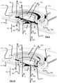
- applanation cover 13 With reference to figures 9 to 12 , an example of applanation cover 13 according to the invention is illustrated.
- the applanation cover 13 makes it possible to flatten the corneal tissue 3 for its imaging or its treatment in isolation (ie without exposing the corneal tissue 3 to the external environment) so as to avoid any risk of contamination.
- the applanation cover 13 comprises a window 131 which can be moved in translation, and a support 132 for connecting the window 131 to the side wall 12 of the device.
- the window 131 is made of a material transparent to radiation (light and electromagnetic) or ultrasound.
- Window 131 can be flat or curved. It comprises an annular bead at its periphery. The annular bead is intended to cooperate with an annular groove of the support 132 to fix the window 131 in a sealed manner on the support 132.
- the support 132 is removably attached to the side wall 12 of the device.
- the support 132 makes it possible to maintain the window 131 in line with the corneal tissue 3.
- the support 132 includes means for moving the window 131 in translation relative to the side wall 12 of the device.
- the user applies (with a microscope or a LASER or any other element) a force in the direction of the corneal tissue 3, perpendicular to the plane containing the window 131 to move the window 131 towards the bottom 11 of the device.
- the window 131 is mobile in translation (rather than in rotation as proposed in WO 2014/140434 ) makes it possible to limit the risks of torsion of the corneal tissue 3 when the window 131 comes into contact with the latter to flatten it, this torsion possibly damaging the corneal tissue 3 as specified previously.
- the support 132 is made of an elastically deformable flexible material. This makes it possible to guarantee the tightness of the cover 13 and thus to improve the sterility of the device.
- the support 132 can comprise a clearance zone to receive part of the gas and/or of the preservation fluid contained in the epithelial chamber 5 when the window 131 is in the active position. This makes it possible to limit the pressure variations in the endothelial and epithelial chambers 4, 5 when the window 131 passes from the rest position to the active position.
- the support 132 is made up of an outer sleeve and the means for moving in translation consist of an annular bellows, the sleeve and the bellows being made in one piece.
- the sleeve is intended to be force-fitted onto the internal face of the side wall 12 (or alternatively clipped onto an external groove of the side wall 12 using anchoring means - such as fastening hooks - mounted on the outer ring).
- the annular bellows extends radially inward from the outer sleeve.
- the free edge of the bellows includes the annular groove intended to cooperate with the annular bead of the window 131 to fix the support 132 and the window 131 together.
- an adhesive - such as glue biocompatible - or any other means known to those skilled in the art can be used to guarantee tight fixing of the window 131 on the support 132.
- the annular bellows can comprise one (or more) fold(s) (successive).
- the fold(s) (of generally rounded concave shape) allow(s) compression and extension of the bellows as well as flexion on either side of its rest position.
- the annular bellows is form-returning, so that when no force is applied to the window 131, the latter returns to the rest position.
- the window 131 automatically returns to the rest position without the user having to perform any action. This makes it possible to prevent corneal tissue 3 from being stored for several weeks while being flattened, which would partially deteriorate it.
- the user When the user wishes to image the corneal tissue 3, for example to check the cellular and tissue quality thereof, he positions a microscope head opposite the window 131, and moves it towards the bottom 11 of the device.
- the displacement of the window 131 towards the corneal tissue induces a reduction in the volume of the epithelial chamber.
- the fold(s) of the bellows (which constitute(s) the release zone) deform(s) in order to receive part of the gas or the fluid contained in the epithelial chamber 5. This limits the pressure variations in the epithelial chamber 5.
- the window 131 comes into contact with the corneal tissue 3. Pressing the window 131 against the corneal tissue 3 tends to flatten the latter. The movement of the window 131 continues until the user stops moving the microscope towards the bottom 11 and/or the window comes into abutment against the inner edge 144 of the retaining ring 14.
- the applanation cover 13 makes it possible to obtain a controlled deformation of the corneal tissue 3 by contact of the window 131 of the cover with the epithelial face of the corneal tissue 3, while keeping the device sealed (closed vessel excluding any risk of contamination ).
- a second type of lid of the device is illustrated, namely a trephination lid 15.
- the trephination lid 15 makes it possible to make a circular incision in the corneal tissue 3. More precisely, the trephination lid makes it possible to perform transfixing or non-transfixing cutting (controlled depth) of the corneal tissue with a view to transfixing or lamellar grafts.
- the outer casing 151 has the general shape of a disc. It includes fixing hooks 154 extending radially outwards at its periphery. Each attachment hook 154 is intended to cooperate with an annular rib 123 made on the outer face of the side wall 12 to allow the attachment of the trephination cover 15 on the side wall 12.
- the central part of the outer casing 151 comprises a through passage including a screw pitch whose known pitch makes it possible to precisely quantify the penetration of the blade.
- the outer face of the blade holder 152 comprises, between its proximal and distal ends, a thread complementary to the thread of the outer casing 151.
- the principle of operation of the trephination cover 15 is as follows. Once the trephination cover 15 has been fixed to the side wall 12 of the device, the user screws the blade holder 152 onto the outer casing 151 using the gripping means. This induces the displacement of the cylindrical blade 153 (very slowly) towards the corneal tissue 3 according to a helical movement. The cutting blade formed by the lower edge of the cylindrical blade 153 penetrates the corneal tissue 3 and allows a circular cut to be made by the epithelial face, thus minimizing endothelial lesions and with vertical edges.
- the pressure can be maintained in the endothelial chamber 4 throughout the operation of trephining the corneal tissue 3.
- the presence of a zone of weakness on the elastic legs makes it possible to make them breakable under the action of a force of intensity greater than a breaking threshold of the zone of weakness . This facilitates the disassembly of the side wall 12 in order to release the corneal tissue 3 during a transplant surgical procedure.
Landscapes
- Life Sciences & Earth Sciences (AREA)
- Health & Medical Sciences (AREA)
- Zoology (AREA)
- Dentistry (AREA)
- General Health & Medical Sciences (AREA)
- Wood Science & Technology (AREA)
- Engineering & Computer Science (AREA)
- Environmental Sciences (AREA)
- Agricultural Chemicals And Associated Chemicals (AREA)
- Physics & Mathematics (AREA)
- Thermal Sciences (AREA)
- Hematology (AREA)
- Prostheses (AREA)
Claims (10)
- Medizinische Vorrichtung zur Konservierung eines zuvor entnommenen Hornhautgewebes (3), wobei die Vorrichtung einen mindestens teilweise durchsichtigen Boden (11), mindestens eine Seitenwand (12), Aufnahme- und Arretierungsmittel des Hornhautgewebes (3) und eine Applanationsabdeckung (13) zum Abdecken einer Öffnung gegenüber dem Boden (11) umfasst, wobei die Applanationsabdeckung (13) ein transparentes Fenster (131) einschließt,
dadurch gekennzeichnet, dass die Applanationsabdeckung (13) ferner einen Träger (132) zwischen dem Fenster (131) und der Seitenwand (12) einschließt, wobei der Träger (132) Translationsverlagerungsmittel des Fensters (131) im Verhältnis zur Seitenwand (12) der Vorrichtung aufweist. - Vorrichtung nach Anspruch 1, wobei der Träger (132) aus einem flexiblen elastisch verformbaren Material besteht.
- Vorrichtung nach einem der Ansprüche 1 oder 2, die derart ausgelegt ist, dass im Gebrauch die Aufnahme- und Arretierungsmittel (14) mit dem Boden (11), dem Hornhautgewebe (3), der Seitenwand (12) und der Abdeckung (13) eine Endothelkammer (4) und eine Epithelkammer (5) definieren, wobei die Endothel- und Epithelkammer Einlass- und Auslassöffnungen für die Zirkulation eines Gases und/oder eines Fluids zur Konservierung einschließt, wobei der Träger (132) eine Freigabezone umfasst, um einen Teil des in der Epithelkammer (5) enthaltenen Gases und/oder Fluids zur Konservierung aufzunehmen, wenn das Fenster (131) translatorisch zum Boden (11) verlagert ist.
- Vorrichtung nach einem der Ansprüche 1 bis 3, wobei die Translationsverlagerungsmittel einen ringförmigen Balg mit mindestens einer Falte umfassen.
- Vorrichtung nach Anspruch 4, wobei der ringförmige Balg aus einem Material besteht, das in seine Form zurückkehrt.
- Vorrichtung nach einem der Ansprüche 1 bis 5, wobei die Seitenwand (12) eine ringförmige Rille (123) umfasst.
- Vorrichtung nach einem der Ansprüche 1 bis 6, die ferner eine Trepanationsabdeckung umfasst, die eine kreisförmige äußere Hülle (151), einen Plättchenhalter (152) und ein zylindrisches Plättchen (153) einschließt, wobei die Applanationsabdeckung durch die Trepanationsabdeckung ersetzbar ist, um eine Öffnung gegenüber dem Boden (11) abzudecken, beispielsweise um das Hornhautgewebe zu schneiden.
- Vorrichtung nach den Ansprüchen 6 und 7, herangezogen in Kombination, wobei die äußere Hülle (151) der Trepanationsabdeckung mindestens zwei Befestigungshaken (154) an ihren Umfang aufweist, wobei sich die Befestigungshaken (154) radial erstrecken und bestimmt sind, mit der in der äußeren Fläche der Seitenwand (12) eingerichteten Rille (123) zusammenzuwirken.
- Vorrichtung nach einem der Ansprüche 1 bis 8, wobei die Seitenwand (12) einen Umfangsrand (122) umfasst und der Boden (11) Rastmittel (111) umfasst, wobei die Rastmittel aus mindestens zwei elastischen Füßen bestehen, die zum Zusammenwirken mit dem Umfangsrand (122) bestimmt sind.
- Vorrichtung nach Anspruch 9, wobei die Rastmittel (111) mindestens drei elastische, um die Seitenwand (12) gleichmäßig verteilte Füße umfassen.
Applications Claiming Priority (2)
| Application Number | Priority Date | Filing Date | Title |
|---|---|---|---|
| FR1762208A FR3074996B1 (fr) | 2017-12-15 | 2017-12-15 | Dispositif medical pour la conservation et/ou le controle qualite et/ou le traitement d'un prelevement corneen incluant un couvercle d'applanation, et eventuellement un couvercle de trepanation |
| PCT/EP2018/084916 WO2019115753A1 (fr) | 2017-12-15 | 2018-12-14 | Dispositif medical pour la conservation d'un tissu corneen incluant un couvercle d'applanation, et eventuellement un couvercle de trepanation |
Publications (2)
| Publication Number | Publication Date |
|---|---|
| EP3723481A1 EP3723481A1 (de) | 2020-10-21 |
| EP3723481B1 true EP3723481B1 (de) | 2022-02-02 |
Family
ID=61187514
Family Applications (1)
| Application Number | Title | Priority Date | Filing Date |
|---|---|---|---|
| EP18826254.7A Active EP3723481B1 (de) | 2017-12-15 | 2018-12-14 | Medizinische vorrichtung zur konservierung von hornhautgewebe, mit einer applanationsabdeckung und optional einer trepanationsabdeckung |
Country Status (10)
| Country | Link |
|---|---|
| US (1) | US11229201B2 (de) |
| EP (1) | EP3723481B1 (de) |
| JP (1) | JP2021506960A (de) |
| CN (1) | CN111787797A (de) |
| AU (1) | AU2018382984A1 (de) |
| CA (1) | CA3085667A1 (de) |
| ES (1) | ES2911181T3 (de) |
| FR (1) | FR3074996B1 (de) |
| IL (1) | IL275332A (de) |
| WO (1) | WO2019115753A1 (de) |
Families Citing this family (7)
| Publication number | Priority date | Publication date | Assignee | Title |
|---|---|---|---|---|
| FR3074997B1 (fr) * | 2017-12-15 | 2019-11-08 | Universite Jean Monnet | Dispositif medical sous forme de cassette pour la conservation et/ou le controle qualite et/ou le traitement d'un prelevement corneen |
| FR3099045B1 (fr) * | 2019-07-22 | 2021-07-30 | Univ Jean Monnet Saint Etienne | Procede de production d’une pluralite d’implants a partir d’une cornee humaine ou animale prealablement prelevee |
| CN111959944B (zh) * | 2020-07-29 | 2025-07-15 | 广东博与再生医学有限公司 | 一种人工角膜保存盒 |
| CN115816551A (zh) * | 2022-10-31 | 2023-03-21 | 广州爱尔眼科医院有限公司 | 角膜基质透镜重塑装置 |
| FR3144160B1 (fr) * | 2022-12-23 | 2025-11-07 | Centre Detude Des Cellules Souches Cecs | Dispositif clos de culture et de transport de produit de thérapie cellulaire |
| CN117122468B (zh) * | 2023-08-14 | 2024-04-09 | 济南市明水眼科医院股份有限公司 | 一种角膜基质透镜环制作器 |
| US20260026496A1 (en) * | 2024-07-25 | 2026-01-29 | BioMedInnovations, Inc. | Ex vivo whole eyeball preservation system |
Family Cites Families (14)
| Publication number | Priority date | Publication date | Assignee | Title |
|---|---|---|---|---|
| IL115390A (en) | 1995-09-21 | 2001-07-24 | Abdulrazik Mohammad | Diffusion cell for ex-vivo pressure-controlled transcorneal drug penetration studies |
| WO2006052478A1 (en) * | 2004-10-26 | 2006-05-18 | Surgical Specialities Corporation | Apparatus and method for in vitro storage of a cornea |
| US20080294149A1 (en) * | 2007-05-25 | 2008-11-27 | Arthur Krolman | Corneal Viewing Chamber |
| CN201243574Y (zh) * | 2008-07-31 | 2009-05-27 | 于涛 | 角膜灌流培养保存装置 |
| FR2944185B1 (fr) * | 2009-04-09 | 2011-05-27 | Peritesco | Chambre de perfusion pour cornee |
| US9167809B2 (en) * | 2009-06-17 | 2015-10-27 | Numedis Incorporated | Cornea storage container to maximize cornea health |
| FR2965254A1 (fr) | 2010-09-28 | 2012-03-30 | Air Liquide | Conteneur de transport et de preservation de materiels biologiques |
| WO2014140434A1 (fr) * | 2013-03-14 | 2014-09-18 | Universite Jean Monnet | Dispositif medical destine a la conservation longue duree d'une cornee, ou a l'experimentation ex vivo sur cornee humaine ou animale |
| ITRM20130713A1 (it) * | 2013-12-23 | 2015-06-24 | Roberta Foglia | Dispositivo per la movimentazione ed il trasporto di un bulbo oculare. |
| DE102014222547B3 (de) | 2014-11-05 | 2016-02-25 | Fraunhofer-Gesellschaft zur Förderung der angewandten Forschung e.V. | Bioreaktorsystem und Verfahren zur Langzeitstabilisierung von Korneagewebe |
| CN204860784U (zh) * | 2015-07-31 | 2015-12-16 | 深圳艾尼尔角膜工程有限公司 | 一种角膜承载装置 |
| WO2017020795A1 (zh) * | 2015-07-31 | 2017-02-09 | 深圳艾尼尔角膜工程有限公司 | 一种角膜保存和复水装置 |
| CN205431779U (zh) * | 2016-01-04 | 2016-08-10 | 广州中大南沙科技创新产业园有限公司 | 脱细胞异种生物角膜干燥装置 |
| FR3074997B1 (fr) * | 2017-12-15 | 2019-11-08 | Universite Jean Monnet | Dispositif medical sous forme de cassette pour la conservation et/ou le controle qualite et/ou le traitement d'un prelevement corneen |
-
2017
- 2017-12-15 FR FR1762208A patent/FR3074996B1/fr not_active Expired - Fee Related
-
2018
- 2018-12-14 ES ES18826254T patent/ES2911181T3/es active Active
- 2018-12-14 US US16/772,653 patent/US11229201B2/en active Active
- 2018-12-14 AU AU2018382984A patent/AU2018382984A1/en not_active Abandoned
- 2018-12-14 EP EP18826254.7A patent/EP3723481B1/de active Active
- 2018-12-14 WO PCT/EP2018/084916 patent/WO2019115753A1/fr not_active Ceased
- 2018-12-14 CN CN201880080896.5A patent/CN111787797A/zh active Pending
- 2018-12-14 CA CA3085667A patent/CA3085667A1/fr active Pending
- 2018-12-14 JP JP2020552127A patent/JP2021506960A/ja active Pending
-
2020
- 2020-06-14 IL IL275332A patent/IL275332A/en unknown
Also Published As
| Publication number | Publication date |
|---|---|
| FR3074996A1 (fr) | 2019-06-21 |
| WO2019115753A1 (fr) | 2019-06-20 |
| US11229201B2 (en) | 2022-01-25 |
| US20210084892A1 (en) | 2021-03-25 |
| EP3723481A1 (de) | 2020-10-21 |
| ES2911181T3 (es) | 2022-05-18 |
| CA3085667A1 (fr) | 2019-06-20 |
| AU2018382984A1 (en) | 2020-06-25 |
| CN111787797A (zh) | 2020-10-16 |
| FR3074996B1 (fr) | 2019-11-08 |
| JP2021506960A (ja) | 2021-02-22 |
| IL275332A (en) | 2020-07-30 |
Similar Documents
| Publication | Publication Date | Title |
|---|---|---|
| FR3074996B1 (fr) | Dispositif medical pour la conservation et/ou le controle qualite et/ou le traitement d'un prelevement corneen incluant un couvercle d'applanation, et eventuellement un couvercle de trepanation | |
| EP3723482B1 (de) | Medizinische vorrichtung in form einer kassette zur konservierung einer hornhautprobe | |
| ES2834469T3 (es) | Dispositivo de llenado de jeringa de gas y métodos de fabricación y utilización de este | |
| EP2991479B1 (de) | Medizinische vorrichtung zur aufbewahrung einer hornhaut | |
| FR2709738A1 (fr) | Procédé et dispositif de distribution et de conditionnement d'un produit fluide contenu dans un récipient pressurisé à l'aide d'un gaz propulseur. | |
| CA2983194C (fr) | Procede de prelevement de micro-organismes, dispositif de prelevement de micro-organismes et kit de prelevement comprenant un tel dispositif de prelevement | |
| FR2714824A1 (fr) | Dispositif à carpule pour la distribution d'un liquide. | |
| US20190038402A1 (en) | Prosthetic heart valve cooling | |
| CA3086065C (fr) | Dispositif medical sous forme de cassette pour la conservation d'un prelevement corneen | |
| CH634999A5 (fr) | Dispositif pour l'evacuation des fluides d'une plaie. | |
| EP4076263B1 (de) | Anordnung mit einer implantierbaren medizinischen vorrichtung und verpackung für diese vorrichtung | |
| EP4076270B1 (de) | Verfahren zum entleeren einer implantierbaren medizinischen vorrichtung | |
| HK40038035A (en) | Medical device for preservation of corneal tissue, comprising an applanation cover, and optionally a trepanation cover | |
| HK40037629A (zh) | 用於保存角膜标本的盘盒形式的医疗设备 | |
| HK40037629B (en) | Medical device in the form of a cartridge for preservation of a corneal specimen | |
| EP3430902A1 (de) | Lebenserhaltende vorrichtung für explantat | |
| FR2985431A1 (fr) | Dispositif pour etancheifier un dispositif de contre pression obture |
Legal Events
| Date | Code | Title | Description |
|---|---|---|---|
| STAA | Information on the status of an ep patent application or granted ep patent |
Free format text: STATUS: UNKNOWN |
|
| STAA | Information on the status of an ep patent application or granted ep patent |
Free format text: STATUS: THE INTERNATIONAL PUBLICATION HAS BEEN MADE |
|
| PUAI | Public reference made under article 153(3) epc to a published international application that has entered the european phase |
Free format text: ORIGINAL CODE: 0009012 |
|
| STAA | Information on the status of an ep patent application or granted ep patent |
Free format text: STATUS: REQUEST FOR EXAMINATION WAS MADE |
|
| 17P | Request for examination filed |
Effective date: 20200624 |
|
| AK | Designated contracting states |
Kind code of ref document: A1 Designated state(s): AL AT BE BG CH CY CZ DE DK EE ES FI FR GB GR HR HU IE IS IT LI LT LU LV MC MK MT NL NO PL PT RO RS SE SI SK SM TR |
|
| AX | Request for extension of the european patent |
Extension state: BA ME |
|
| DAV | Request for validation of the european patent (deleted) | ||
| DAX | Request for extension of the european patent (deleted) | ||
| GRAP | Despatch of communication of intention to grant a patent |
Free format text: ORIGINAL CODE: EPIDOSNIGR1 |
|
| STAA | Information on the status of an ep patent application or granted ep patent |
Free format text: STATUS: GRANT OF PATENT IS INTENDED |
|
| INTG | Intention to grant announced |
Effective date: 20210824 |
|
| GRAS | Grant fee paid |
Free format text: ORIGINAL CODE: EPIDOSNIGR3 |
|
| GRAA | (expected) grant |
Free format text: ORIGINAL CODE: 0009210 |
|
| STAA | Information on the status of an ep patent application or granted ep patent |
Free format text: STATUS: THE PATENT HAS BEEN GRANTED |
|
| AK | Designated contracting states |
Kind code of ref document: B1 Designated state(s): AL AT BE BG CH CY CZ DE DK EE ES FI FR GB GR HR HU IE IS IT LI LT LU LV MC MK MT NL NO PL PT RO RS SE SI SK SM TR |
|
| REG | Reference to a national code |
Ref country code: GB Ref legal event code: FG4D Free format text: NOT ENGLISH |
|
| REG | Reference to a national code |
Ref country code: CH Ref legal event code: EP Ref country code: AT Ref legal event code: REF Ref document number: 1466339 Country of ref document: AT Kind code of ref document: T Effective date: 20220215 |
|
| REG | Reference to a national code |
Ref country code: DE Ref legal event code: R096 Ref document number: 602018030412 Country of ref document: DE |
|
| REG | Reference to a national code |
Ref country code: IE Ref legal event code: FG4D Free format text: LANGUAGE OF EP DOCUMENT: FRENCH |
|
| REG | Reference to a national code |
Ref country code: ES Ref legal event code: FG2A Ref document number: 2911181 Country of ref document: ES Kind code of ref document: T3 Effective date: 20220518 |
|
| REG | Reference to a national code |
Ref country code: LT Ref legal event code: MG9D |
|
| REG | Reference to a national code |
Ref country code: NL Ref legal event code: MP Effective date: 20220202 |
|
| REG | Reference to a national code |
Ref country code: AT Ref legal event code: MK05 Ref document number: 1466339 Country of ref document: AT Kind code of ref document: T Effective date: 20220202 |
|
| PG25 | Lapsed in a contracting state [announced via postgrant information from national office to epo] |
Ref country code: SE Free format text: LAPSE BECAUSE OF FAILURE TO SUBMIT A TRANSLATION OF THE DESCRIPTION OR TO PAY THE FEE WITHIN THE PRESCRIBED TIME-LIMIT Effective date: 20220202 Ref country code: RS Free format text: LAPSE BECAUSE OF FAILURE TO SUBMIT A TRANSLATION OF THE DESCRIPTION OR TO PAY THE FEE WITHIN THE PRESCRIBED TIME-LIMIT Effective date: 20220202 Ref country code: PT Free format text: LAPSE BECAUSE OF FAILURE TO SUBMIT A TRANSLATION OF THE DESCRIPTION OR TO PAY THE FEE WITHIN THE PRESCRIBED TIME-LIMIT Effective date: 20220602 Ref country code: NO Free format text: LAPSE BECAUSE OF FAILURE TO SUBMIT A TRANSLATION OF THE DESCRIPTION OR TO PAY THE FEE WITHIN THE PRESCRIBED TIME-LIMIT Effective date: 20220502 Ref country code: NL Free format text: LAPSE BECAUSE OF FAILURE TO SUBMIT A TRANSLATION OF THE DESCRIPTION OR TO PAY THE FEE WITHIN THE PRESCRIBED TIME-LIMIT Effective date: 20220202 Ref country code: LT Free format text: LAPSE BECAUSE OF FAILURE TO SUBMIT A TRANSLATION OF THE DESCRIPTION OR TO PAY THE FEE WITHIN THE PRESCRIBED TIME-LIMIT Effective date: 20220202 Ref country code: HR Free format text: LAPSE BECAUSE OF FAILURE TO SUBMIT A TRANSLATION OF THE DESCRIPTION OR TO PAY THE FEE WITHIN THE PRESCRIBED TIME-LIMIT Effective date: 20220202 Ref country code: BG Free format text: LAPSE BECAUSE OF FAILURE TO SUBMIT A TRANSLATION OF THE DESCRIPTION OR TO PAY THE FEE WITHIN THE PRESCRIBED TIME-LIMIT Effective date: 20220502 |
|
| PG25 | Lapsed in a contracting state [announced via postgrant information from national office to epo] |
Ref country code: PL Free format text: LAPSE BECAUSE OF FAILURE TO SUBMIT A TRANSLATION OF THE DESCRIPTION OR TO PAY THE FEE WITHIN THE PRESCRIBED TIME-LIMIT Effective date: 20220202 Ref country code: LV Free format text: LAPSE BECAUSE OF FAILURE TO SUBMIT A TRANSLATION OF THE DESCRIPTION OR TO PAY THE FEE WITHIN THE PRESCRIBED TIME-LIMIT Effective date: 20220202 Ref country code: GR Free format text: LAPSE BECAUSE OF FAILURE TO SUBMIT A TRANSLATION OF THE DESCRIPTION OR TO PAY THE FEE WITHIN THE PRESCRIBED TIME-LIMIT Effective date: 20220503 Ref country code: FI Free format text: LAPSE BECAUSE OF FAILURE TO SUBMIT A TRANSLATION OF THE DESCRIPTION OR TO PAY THE FEE WITHIN THE PRESCRIBED TIME-LIMIT Effective date: 20220202 Ref country code: AT Free format text: LAPSE BECAUSE OF FAILURE TO SUBMIT A TRANSLATION OF THE DESCRIPTION OR TO PAY THE FEE WITHIN THE PRESCRIBED TIME-LIMIT Effective date: 20220202 |
|
| PG25 | Lapsed in a contracting state [announced via postgrant information from national office to epo] |
Ref country code: IS Free format text: LAPSE BECAUSE OF FAILURE TO SUBMIT A TRANSLATION OF THE DESCRIPTION OR TO PAY THE FEE WITHIN THE PRESCRIBED TIME-LIMIT Effective date: 20220602 |
|
| PG25 | Lapsed in a contracting state [announced via postgrant information from national office to epo] |
Ref country code: SM Free format text: LAPSE BECAUSE OF FAILURE TO SUBMIT A TRANSLATION OF THE DESCRIPTION OR TO PAY THE FEE WITHIN THE PRESCRIBED TIME-LIMIT Effective date: 20220202 Ref country code: SK Free format text: LAPSE BECAUSE OF FAILURE TO SUBMIT A TRANSLATION OF THE DESCRIPTION OR TO PAY THE FEE WITHIN THE PRESCRIBED TIME-LIMIT Effective date: 20220202 Ref country code: RO Free format text: LAPSE BECAUSE OF FAILURE TO SUBMIT A TRANSLATION OF THE DESCRIPTION OR TO PAY THE FEE WITHIN THE PRESCRIBED TIME-LIMIT Effective date: 20220202 Ref country code: EE Free format text: LAPSE BECAUSE OF FAILURE TO SUBMIT A TRANSLATION OF THE DESCRIPTION OR TO PAY THE FEE WITHIN THE PRESCRIBED TIME-LIMIT Effective date: 20220202 Ref country code: DK Free format text: LAPSE BECAUSE OF FAILURE TO SUBMIT A TRANSLATION OF THE DESCRIPTION OR TO PAY THE FEE WITHIN THE PRESCRIBED TIME-LIMIT Effective date: 20220202 Ref country code: CZ Free format text: LAPSE BECAUSE OF FAILURE TO SUBMIT A TRANSLATION OF THE DESCRIPTION OR TO PAY THE FEE WITHIN THE PRESCRIBED TIME-LIMIT Effective date: 20220202 |
|
| REG | Reference to a national code |
Ref country code: DE Ref legal event code: R097 Ref document number: 602018030412 Country of ref document: DE |
|
| PG25 | Lapsed in a contracting state [announced via postgrant information from national office to epo] |
Ref country code: AL Free format text: LAPSE BECAUSE OF FAILURE TO SUBMIT A TRANSLATION OF THE DESCRIPTION OR TO PAY THE FEE WITHIN THE PRESCRIBED TIME-LIMIT Effective date: 20220202 |
|
| PLBE | No opposition filed within time limit |
Free format text: ORIGINAL CODE: 0009261 |
|
| STAA | Information on the status of an ep patent application or granted ep patent |
Free format text: STATUS: NO OPPOSITION FILED WITHIN TIME LIMIT |
|
| 26N | No opposition filed |
Effective date: 20221103 |
|
| PG25 | Lapsed in a contracting state [announced via postgrant information from national office to epo] |
Ref country code: SI Free format text: LAPSE BECAUSE OF FAILURE TO SUBMIT A TRANSLATION OF THE DESCRIPTION OR TO PAY THE FEE WITHIN THE PRESCRIBED TIME-LIMIT Effective date: 20220202 |
|
| P01 | Opt-out of the competence of the unified patent court (upc) registered |
Effective date: 20230601 |
|
| REG | Reference to a national code |
Ref country code: CH Ref legal event code: PL |
|
| REG | Reference to a national code |
Ref country code: BE Ref legal event code: MM Effective date: 20221231 |
|
| PG25 | Lapsed in a contracting state [announced via postgrant information from national office to epo] |
Ref country code: LU Free format text: LAPSE BECAUSE OF NON-PAYMENT OF DUE FEES Effective date: 20221214 |
|
| PG25 | Lapsed in a contracting state [announced via postgrant information from national office to epo] |
Ref country code: LI Free format text: LAPSE BECAUSE OF NON-PAYMENT OF DUE FEES Effective date: 20221231 Ref country code: CH Free format text: LAPSE BECAUSE OF NON-PAYMENT OF DUE FEES Effective date: 20221231 |
|
| PG25 | Lapsed in a contracting state [announced via postgrant information from national office to epo] |
Ref country code: BE Free format text: LAPSE BECAUSE OF NON-PAYMENT OF DUE FEES Effective date: 20221231 |
|
| PG25 | Lapsed in a contracting state [announced via postgrant information from national office to epo] |
Ref country code: CY Free format text: LAPSE BECAUSE OF FAILURE TO SUBMIT A TRANSLATION OF THE DESCRIPTION OR TO PAY THE FEE WITHIN THE PRESCRIBED TIME-LIMIT Effective date: 20220202 |
|
| PG25 | Lapsed in a contracting state [announced via postgrant information from national office to epo] |
Ref country code: MK Free format text: LAPSE BECAUSE OF FAILURE TO SUBMIT A TRANSLATION OF THE DESCRIPTION OR TO PAY THE FEE WITHIN THE PRESCRIBED TIME-LIMIT Effective date: 20220202 Ref country code: HU Free format text: LAPSE BECAUSE OF FAILURE TO SUBMIT A TRANSLATION OF THE DESCRIPTION OR TO PAY THE FEE WITHIN THE PRESCRIBED TIME-LIMIT; INVALID AB INITIO Effective date: 20181214 |
|
| PG25 | Lapsed in a contracting state [announced via postgrant information from national office to epo] |
Ref country code: MC Free format text: LAPSE BECAUSE OF FAILURE TO SUBMIT A TRANSLATION OF THE DESCRIPTION OR TO PAY THE FEE WITHIN THE PRESCRIBED TIME-LIMIT Effective date: 20220202 |
|
| PG25 | Lapsed in a contracting state [announced via postgrant information from national office to epo] |
Ref country code: TR Free format text: LAPSE BECAUSE OF FAILURE TO SUBMIT A TRANSLATION OF THE DESCRIPTION OR TO PAY THE FEE WITHIN THE PRESCRIBED TIME-LIMIT Effective date: 20220202 Ref country code: MC Free format text: LAPSE BECAUSE OF FAILURE TO SUBMIT A TRANSLATION OF THE DESCRIPTION OR TO PAY THE FEE WITHIN THE PRESCRIBED TIME-LIMIT Effective date: 20220202 |
|
| PG25 | Lapsed in a contracting state [announced via postgrant information from national office to epo] |
Ref country code: MT Free format text: LAPSE BECAUSE OF FAILURE TO SUBMIT A TRANSLATION OF THE DESCRIPTION OR TO PAY THE FEE WITHIN THE PRESCRIBED TIME-LIMIT Effective date: 20220202 |
|
| REG | Reference to a national code |
Ref country code: DE Ref legal event code: R079 Ref document number: 602018030412 Country of ref document: DE Free format text: PREVIOUS MAIN CLASS: A01N0001020000 Ipc: A01N0001100000 |
|
| PGFP | Annual fee paid to national office [announced via postgrant information from national office to epo] |
Ref country code: DE Payment date: 20251211 Year of fee payment: 8 |
|
| PGFP | Annual fee paid to national office [announced via postgrant information from national office to epo] |
Ref country code: GB Payment date: 20251219 Year of fee payment: 8 |
|
| PGFP | Annual fee paid to national office [announced via postgrant information from national office to epo] |
Ref country code: IT Payment date: 20251223 Year of fee payment: 8 |
|
| PGFP | Annual fee paid to national office [announced via postgrant information from national office to epo] |
Ref country code: FR Payment date: 20251229 Year of fee payment: 8 |
|
| PGFP | Annual fee paid to national office [announced via postgrant information from national office to epo] |
Ref country code: IE Payment date: 20251219 Year of fee payment: 8 |
|
| PGFP | Annual fee paid to national office [announced via postgrant information from national office to epo] |
Ref country code: ES Payment date: 20260130 Year of fee payment: 8 |