EP3722668B1 - System comprising an illumination component - Google Patents
System comprising an illumination component Download PDFInfo
- Publication number
- EP3722668B1 EP3722668B1 EP19168645.0A EP19168645A EP3722668B1 EP 3722668 B1 EP3722668 B1 EP 3722668B1 EP 19168645 A EP19168645 A EP 19168645A EP 3722668 B1 EP3722668 B1 EP 3722668B1
- Authority
- EP
- European Patent Office
- Prior art keywords
- cable
- illumination component
- connector device
- light
- shell
- Prior art date
- Legal status (The legal status is an assumption and is not a legal conclusion. Google has not performed a legal analysis and makes no representation as to the accuracy of the status listed.)
- Active
Links
Images


Classifications
-
- F—MECHANICAL ENGINEERING; LIGHTING; HEATING; WEAPONS; BLASTING
- F21—LIGHTING
- F21V—FUNCTIONAL FEATURES OR DETAILS OF LIGHTING DEVICES OR SYSTEMS THEREOF; STRUCTURAL COMBINATIONS OF LIGHTING DEVICES WITH OTHER ARTICLES, NOT OTHERWISE PROVIDED FOR
- F21V17/00—Fastening of component parts of lighting devices, e.g. shades, globes, refractors, reflectors, filters, screens, grids or protective cages
- F21V17/08—Fastening of component parts of lighting devices, e.g. shades, globes, refractors, reflectors, filters, screens, grids or protective cages onto the supporting or suspending arrangements of the lighting device, e.g. power cords, standards
-
- F—MECHANICAL ENGINEERING; LIGHTING; HEATING; WEAPONS; BLASTING
- F21—LIGHTING
- F21S—NON-PORTABLE LIGHTING DEVICES; SYSTEMS THEREOF; VEHICLE LIGHTING DEVICES SPECIALLY ADAPTED FOR VEHICLE EXTERIORS
- F21S8/00—Lighting devices intended for fixed installation
- F21S8/04—Lighting devices intended for fixed installation intended only for mounting on a ceiling or the like overhead structures
- F21S8/06—Lighting devices intended for fixed installation intended only for mounting on a ceiling or the like overhead structures by suspension
- F21S8/061—Lighting devices intended for fixed installation intended only for mounting on a ceiling or the like overhead structures by suspension with a non-rigid pendant, i.e. a cable, wire or chain
-
- F—MECHANICAL ENGINEERING; LIGHTING; HEATING; WEAPONS; BLASTING
- F21—LIGHTING
- F21V—FUNCTIONAL FEATURES OR DETAILS OF LIGHTING DEVICES OR SYSTEMS THEREOF; STRUCTURAL COMBINATIONS OF LIGHTING DEVICES WITH OTHER ARTICLES, NOT OTHERWISE PROVIDED FOR
- F21V21/00—Supporting, suspending, or attaching arrangements for lighting devices; Hand grips
- F21V21/14—Adjustable mountings
- F21V21/16—Adjustable mountings using wires or cords
-
- F—MECHANICAL ENGINEERING; LIGHTING; HEATING; WEAPONS; BLASTING
- F21—LIGHTING
- F21V—FUNCTIONAL FEATURES OR DETAILS OF LIGHTING DEVICES OR SYSTEMS THEREOF; STRUCTURAL COMBINATIONS OF LIGHTING DEVICES WITH OTHER ARTICLES, NOT OTHERWISE PROVIDED FOR
- F21V21/00—Supporting, suspending, or attaching arrangements for lighting devices; Hand grips
- F21V21/36—Hoisting or lowering devices, e.g. for maintenance
- F21V21/38—Hoisting or lowering devices, e.g. for maintenance with a cable
-
- F—MECHANICAL ENGINEERING; LIGHTING; HEATING; WEAPONS; BLASTING
- F21—LIGHTING
- F21V—FUNCTIONAL FEATURES OR DETAILS OF LIGHTING DEVICES OR SYSTEMS THEREOF; STRUCTURAL COMBINATIONS OF LIGHTING DEVICES WITH OTHER ARTICLES, NOT OTHERWISE PROVIDED FOR
- F21V23/00—Arrangement of electric circuit elements in or on lighting devices
- F21V23/001—Arrangement of electric circuit elements in or on lighting devices the elements being electrical wires or cables
-
- F—MECHANICAL ENGINEERING; LIGHTING; HEATING; WEAPONS; BLASTING
- F21—LIGHTING
- F21V—FUNCTIONAL FEATURES OR DETAILS OF LIGHTING DEVICES OR SYSTEMS THEREOF; STRUCTURAL COMBINATIONS OF LIGHTING DEVICES WITH OTHER ARTICLES, NOT OTHERWISE PROVIDED FOR
- F21V23/00—Arrangement of electric circuit elements in or on lighting devices
- F21V23/06—Arrangement of electric circuit elements in or on lighting devices the elements being coupling devices, e.g. connectors
-
- F—MECHANICAL ENGINEERING; LIGHTING; HEATING; WEAPONS; BLASTING
- F21—LIGHTING
- F21V—FUNCTIONAL FEATURES OR DETAILS OF LIGHTING DEVICES OR SYSTEMS THEREOF; STRUCTURAL COMBINATIONS OF LIGHTING DEVICES WITH OTHER ARTICLES, NOT OTHERWISE PROVIDED FOR
- F21V27/00—Cable-stowing arrangements structurally associated with lighting devices, e.g. reels
-
- H—ELECTRICITY
- H01—ELECTRIC ELEMENTS
- H01R—ELECTRICALLY-CONDUCTIVE CONNECTIONS; STRUCTURAL ASSOCIATIONS OF A PLURALITY OF MUTUALLY-INSULATED ELECTRICAL CONNECTING ELEMENTS; COUPLING DEVICES; CURRENT COLLECTORS
- H01R39/00—Rotary current collectors, distributors or interrupters
- H01R39/02—Details for dynamo electric machines
- H01R39/08—Slip-rings
- H01R39/12—Slip-rings using bearing or shaft surface as contact surface
Definitions
- the invention is directed to a system comprising an illumination component, a cable configured to be mechanically connected to the illumination component, in particular comprising an electrical apparatus, and a winch configured to wind and/or unwind the cable, wherein the system is configured to supply power and/or data to the illumination component via the cable.
- an illumination component in particular, comprising electrical apparatus like a lighting apparatus, in such a manner that it is mechanically and electrically connected to a cable.
- the cable can be used to mechanically attach the illumination component to its surroundings via the winch.
- the cable is wound around the winch and the winch may be attached to any desired element in said surroundings. By winding or unwinding the cable, the length of unwound cable can be adjusted.
- the system can supply power and/or data to the illumination component via the cable, usually via a wiring, which is enclosed in a sheath of the cable.
- EP 3 450 385 A1 A system is proposed in EP 3 450 385 A1 , wherein an object is suspended from a winch using a rope, the rope and the object being connected using a spin prevention device.
- a power supply board which has an essentially fixed position.
- the power supply board is then used to charge a battery, which may power the object in operation. Accordingly, continuous supply with external power or data is not possible in operation.
- KR 2011 0012878 discloses a prior art system.
- the problem underlying the invention is to provide a system that still allows for continuous supply with external power and/or data during operation, in which the risk for damages to and increased wear of the cable is reduced.
- the system comprising the illumination component, the cable configured to be mechanically connected to the illumination component, in particular comprising an electrical apparatus, and the winch configured to wind and/or unwind the cable, and configured to supply power and/or data to the illumination component via the cable
- the invention comprises a connector device comprising a bearing and configured to mechanically connect the illumination component to the cable in such a manner that, in a connected state, at least part of the illumination component is rotationally decoupled from the cable by means of the bearing, wherein the rotation refers to a rotation around an extension of the longitudinal axis of the unwound and tensioned portion of the cable.
- the precision of controlling the position of the illumination component may also suffer. That is, the effective length of unwound cable may shorten unpredictably, depending on how much twist has occurred. Moreover, in some cases the twisted cable may also show different characteristics, when compared to a cable that is not twisted, when winding it on the winch. In ideal conditions, the cable and winch will be configured so as to allow for adjacent turns of the cable coil on the winch to be neatly aligned. However, when the cable is twisted, this neat alignment may in some cases be impeded by the twisted cable.
- the part of the illumination component from which the cable is decoupled will herein be referred to as the decoupled part of the illumination component or, in abbreviated from, as the decoupled part.
- connections, coupling, or decoupling refer to a connected state, where the cable is mechanically and, where applicable, electrically, connected to the illumination component, unless otherwise specified. Moreover, unless specified otherwise, the system is described herein in an assembled state and in the arrangement, in particular mounting, corresponding to its designated use.
- the connector device being configured to connect the illumination component to the cable may comprise that the cable is attached directly to the connector device and/or directly to another element, in particular a non-decoupled part of the illumination component.
- a first, non-decoupled part of the illumination component may be directly attached to the cable and to a first portion of the connector device
- a second, decoupled part of the illumination component may be attached, directly or indirectly, to a second portion of the connector device, the two portions being rotationally decoupled. This would still be considered as the connector device connecting the cable and the illumination component, although the cable may be attached to some part of the illumination component directly and possibly may even only indirectly be attached to the first portion of the connector device.
- Rotationally decoupled means that a rotation of the decoupled part of the illumination component is decoupled from the cable irrespective of the amount of rotation of the decoupled part. For example, even a rotation of 360° or more is decoupled.
- the connector device is configured so as to avoid that a rotation of the decoupled part, irrespective of the amount of rotation, is translated to a rotation of the cable.
- the rotation shall refer to a rotation around an extension of the longitudinal axis (i.e., the axis along its biggest expansion) of the unwound and tensioned portion of the cable. Twisting of the cable refers to a torsion of the cable around said longitudinal axis in the unwound portion of the cable.
- the cable is configured to provide power and/or data, for example electrical signals, to the illumination component.
- the cable may comprise a sheath and wirings.
- the wirings may be used for the power and/or data transfer.
- the system described herein in particular when it comes to the cable-winch arrangement, may be based on the system as described in the patent document EP 2 466 252 B1 .
- the winch described herein may be configured to wind and/or unwind the cable so as to provide a predetermined length of unwound cable.
- the winding and unwinding may be achieved by driving means driving the winch, e.g., controlled by a controller.
- the bearing may, for example, comprise a ball bearing or a roller bearing.
- the connector device may comprise, or be mechanically connected, with a strain relief element, which is configured to guide the cable in such a way that strain on the electrical connection between the cable and the illumination component is reduced compared to a system not having such a strain relief.
- the strain relief element may be configured such that the mechanical strain on the wirings of the cable and/or the wirings of the electronic device and/or a plug connecting the wirings is reduced.
- the illumination component may then be mechanically attached to the strain relief element via the connector device and/or any non-decoupled part of the illumination component may be mechanically attached to the strain relief element directly.
- the cable may be mechanically attached to the strain relief element in such a manner that a free end of the cable is provided, which, in a connected state, provides the connection to the illumination component, directly or via the connector device.
- a free end of the cable is an end that is not tensioned.
- the illumination component may comprise at least a first part and a second part and the connector device may be configured to rotationally decouple the first part and the second part from the cable or to rotationally decouple only the second part from the cable.
- the connector device may be configured to rotationally decouple only one, several, or all of said parts from the cable.
- both the first and the second part are decoupled from the cable, they may be attached to each other and/or both attached to the same bearing.
- each of the first and second part may be rotationally decoupled independently of each other.
- the parts may be rotationally decoupled by means of separate bearings.
- the second part may be decoupled from the cable.
- the second part may have a bigger mass and/or moment of inertia than the first part.
- the risk of the cable twisting increases with the mass and moment of inertia of any object that is fixedly attached to its end. Therefore, when only part of the illumination component is decoupled, it is advantageous that this be the heavier part thereof and/or the one with the bigger moment of inertia.
- the connector device still allows for other, e.g., non-decoupled, parts of the illumination component to be attached directly to the cable or to the portion of the connector device that is attached to the cable.
- a non-moving electrical connection between the cable and said part having a lower mass or moment of inertia can be achieved with ease.
- the illumination component comprises a light-emitting device.
- Such a device may be relatively lightweight, as it may only comprise a bulb or LED element, for example. The risk of the cable twisting will not be greatly increased when this light-emitting device is not rotationally decoupled from the cable and at the same time, the electrical connection can be made easily by means of plug connections, for example.
- the light-emitting device is arranged in a direction extending along the longitudinal axis of the unwound portion of the cable, it is likely to have a lower moment of inertia than other parts of the illumination component, for example a shell or lampshade.
- the cable may be attached to a first portion of the connector device, in particular in a fixed relative position
- the decoupled part of the illumination component may be attached to a second portion of the connector device, in particular in a fixed relative position
- the first and second portion of the connector device may be freely rotatable with respect to each other.
- the connector device is configured such that, irrespective of the amount of rotation, the first portion is rotationally decoupled from the second portion. This may be achieved, for example, by means of the bearing and the two portions being attached to two respective parts of the bearing.
- a fixed relative position particularly means that there is no relative movement between the attached elements.
- the cable and/or decoupled part may be attached to the respective portion by means of detachable connections, for example positive form locking, plug connections, screw connections, or the like.
- detachable connections for example positive form locking, plug connections, screw connections, or the like.
- the cable in addition to or alternatively to these connections, as described above, it is possible to attach the cable to a strain relief, which may be part of the connector device or external to the connector device.
- the first portion of the connector device may comprise or be connected to such a strain relief.
- the first portion of the connector device may be attached to the first part of the illumination component, particularly in a fixed relative position, and the second portion of the connector device may be connected to the second part of the illumination component, particularly in a fixed relative position.
- the first part of the illumination component is rotationally decoupled from and, accordingly, freely rotatable with respect to, the second part of the illumination component.
- the attachment may, for example, be achieved by any of the attachment means described above.
- the illumination component may comprise an electrical apparatus and the above-described first part of the illumination component may comprise parts of the electrical apparatus to be supplied with power and/or data via the cable. As described above, the first part may not be decoupled from the cable.
- the first part may comprise a light-emitting device comprising one or more light-emitting elements, for example an LED, an LED panel, lightbulb, fluorescent tube or the like, and, optionally, a controller configured to control the light-emitting elements.
- the parts of the electrical apparatus to be provided with power and/or signals via the cable may have an electrical connection with the cable, the connection bypassing the connector device, in particular a direct connection between a wiring of the cable and a wiring of the electrical apparatus.
- a wiring of the cable may be connected with a wiring of the electrical apparatus by means of a plug connection, without involving any elements of the connector device.
- the wiring from the cable or attached to the cable may bypass the connector device by extending around it.
- the illumination component may comprise an electrical apparatus.
- the system may be configured to transmit power and/or data from the cable to the electrical apparatus via the connector device.
- connection of the above-described first portion of the connector device with the cable e.g., a plug connection
- a connection of the above-described second portion of the connector device with the parts of the electrical apparatus to be provided with power and/or data via the cable may be configured such that they do not require a gliding connection or contactless interface. Accordingly, different illumination components and cables can easily be combined without any special requirements, since it is possible for the connector device to provide, where necessary, a gliding connection or contactless interface, irrespective of the elements attached thereto.
- the connector device may comprise an electrical contact, e.g., a gliding contact, electrically connecting the first portion and the second portion of the connector device, and/or a contactless transfer interface, e.g., coils, configured to transfer power and/or data between the first portion and the second portion of the connector device.
- an electrical contact e.g., a gliding contact
- a contactless transfer interface e.g., coils
- the connector device allows for providing power and/or data essentially without impeding the decoupling.
- An example for a gliding contact comprises a slip ring arrangement.
- An example for contactless transfer is transfer via coils by means of electromagnetic induction.
- the illumination component may comprise a lighting apparatus having a light-emitting device and a shell, wherein the shell at least partially encloses the light-emitting device, and wherein the above-described first part, i.e., the part that may be, but is not necessarily, decoupled from the cable, comprises the light-emitting device and the second part, i.e. the part that is decoupled from the cable, comprises the shell.
- the connector device allows for rotationally decoupling the light-emitting device and the shell from the cable or for rotationally decoupling only the shell from the cable.
- the shell may be at least partially transparent or translucent, such that light emitted by the light-emitting device may be emitted through the shell.
- the shell may comprise a lampshade.
- the form of the shell is not limited, but it may, for example, be tube-shaped, spherical, or cuboid.
- the shell may be constituted by one or more of glass, plastic, paper, and textile.
- the illumination component may comprise a or the lighting apparatus comprising a or the light-emitting device, and a or the shell, wherein the shell at least partially encloses the light-emitting device, and wherein the connector device is configured to rotationally decouple, in particular only, the shell from the cable.
- the system may in such a case be further configured such that power and/or data are provided from the cable to the light-emitting device by means of an electrical contact and/or by means of a contactless transfer interface for transferring power and/or data, e.g., via coils, as has been described in a different context above and is equally applicable in this specific context.
- the connector device may comprise the electrical contact and/or contactless transfer interface for transferring power and/or data.
- the system comprises alternative or additional electrical contacts or interfaces.
- the illumination component may comprise at least one of a light-reflecting element, a diffusor, a fluorescent element, and a phosphorescent element.
- the illumination component may comprise a mirror and/or, as seen above, an electrical apparatus like a lighting apparatus.
- the winch when the system is assembled and mounted for its designated use, the winch may be mounted to a building, for example the walls and or ceiling thereof, in particular on the inside of the building, and/or to a rack or a framework or a beam, in particular mounted on the inside of a or the building.
- a framework on which the winch is mounted may be a scaffold or may be suspended from the ceiling.
- the inside of a building may comprise a hangar, lobby, hallway or the like.
- the cable when the system is assembled and mounted for its designated use, the cable may be tensioned, for example by a force directed away from the winch, in particular gravity.
- the illumination component when the system is assembled and mounted for its designated use, the illumination component may be suspended, via the cable, from the winch, which is in particular mounted to at least one of a ceiling, a rack, a framework, and a beam.
- any of the above-described systems may be used in an arrangement of a plurality of systems each comprising a winch, a cable, and an illumination component, particularly a plurality of systems as described above.
- the plurality of systems may be arranged adjacently to each other, for example in a line or an array.
- the arrangement may further comprise a controller and the systems may be connected to the controller via a data connection, the controller configured to control the operation of the winches, e.g. to wind and/or unwind a predetermined length of the cable, and optionally the operation of the illumination components, in a coordinated manner.
- a precise control of the effective length of the cable is particularly important, so as to ensure that the illumination components are moved by a precise amount that is determined by the controlled operation of the winches to wind and/or unwind the cable. Accordingly, avoiding that the cable is twisted is advantageous in that it allows for avoiding deviations in the effective length of the unwound portion of the cable.
- the above described systems and arrangement may for example be used for installations that comprise illumination components, which may, for example, be lighting elements or may be irradiated with external light sources to provide illumination by means of reflection or phosphorescence for example.
- illumination components which may, for example, be lighting elements or may be irradiated with external light sources to provide illumination by means of reflection or phosphorescence for example.
- such installations may be provided indoors, particularly in high-ceilinged halls or the like.
- a coordinated operation of the winches and the external light sources and/or illumination components in the form of lighting elements may be used for light shows, in particular such that changing geometrical forms may mimicked with a plurality of illumination components.
- a precise control of the position of the illumination components is particularly important in such scenarios. Accordingly, avoiding that the cable is twisted is advantageous in that it allows for avoiding deviations in the effective length of the unwound portion of the cable.
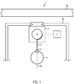
- Figure 1 shows a system 1 according to the invention comprising a winch 2, a cable 3, and an illumination component 4.
- a longitudinal axis 3a of the unwound and tensioned portion of the cable is also shown.
- the winch is configured to wind and/or unwind the cable.
- a connector device 5 is schematically shown.
- the connector device 5 mechanically connects the cable and the illumination component in such a manner that at least part of the illumination component is rotationally decoupled from the cable in a connected state.
- the winch is here shown as being attached to and suspended from a framework 6a, but it may alternatively be attached to a ceiling 6b of a building, for example.
- the illumination component is suspended from the framework via the cable.
- the framework may be standing, e.g., in the form of a scaffold, as suggested in Figure 1 or it may be suspended from the ceiling.
- the winch may comprise or be connected to an external control device 7 configured to control the operation of the winch and/or the illumination component.
- the system is configured to supply power and/or data to the illumination component via the cable. Details in this respect are provided below.
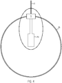
- Figures 2 and 3 show a first embodiment, in which the illumination component comprises an electrical apparatus, in particular, a lighting apparatus.
- the lighting apparatus comprises a first part 4a in the form of a light-emitting device.
- the lighting apparatus also comprises a second part 4b, in the present example in the form of a shell that at least partially encloses the light-emitting device.
- the shell may optionally be transparent or translucent so as to transmit part of the emitted light or it may be opaque and have openings through which the light is emitted.
- the cable 3 and the light-emitting device 4a are attached to a first portion 5a of the connector device.
- the cable is attached to the first portion of the connector device via the first part of the lighting apparatus, but it may also be directly attached to the first portion of the connector device.
- the second part 4b of the lighting apparatus i.e., the shell, is attached to a second portion 5b of the connector device.
- the second portion is rotatably supported on the first portion via a bearing 8. However, it is equally possible to support the first portion on the second portion, depending on the geometry.
- the connector device rotationally decouples the second part 4b of the lighting apparatus from the cable and from the first part 4a of the lighting apparatus.
- the second part, in this case the shell, of the lighting apparatus rotates
- the second portion of the connector device will rotate together with the shell.
- the rotation is transferred to the first portion of the connector device.
- the first part of the lighting apparatus and the cable are attached to the first portion of the connector device, but not to the second portion thereof or the second part of the lighting apparatus.
- the rotation will also not be translated to them. Therefore, the second part, here shell, of the lighting apparatus may rotate, but a rotation of the cable can be avoided. In view of this, the risk that the cable will be twisted around its longitudinal axis (of the unwound and tensioned portion) is reduced.
- the cable may have wiring and a sheath.
- the wiring of the cable may be connected, for example via a plug connection, directly to wiring of the first part of the light-emitting device.
- the wiring of the cable and the wiring of the lighting apparatus may each be connected, for example via a plug connection, to wiring of the first portion of the connector device, such that the electrical contact between the cable and the light-emitting device may be obtained through the first portion of the connector device.
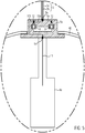
- the illumination component comprises an electrical apparatus, in particular, a lighting apparatus.
- the lighting apparatus comprises a first part 4a in the form of a light-emitting device.
- the lighting apparatus also comprises a second part 4b, in the present example in the form of a shell that at least partially encloses the light-emitting device.
- the shell may optionally be transparent or translucent so as to transmit part of the emitted light, or it may be opaque and have openings through which the light is emitted.
- the cable 3 is attached to a first portion 5a of the connector device.
- the first part 4a and second part 4b i.e., the light-emitting device and the shell, are each attached to a second portion 5b of the connector device.
- the connector device rotationally decouples the first part 4a and the second part 4b of the lighting apparatus from the cable.
- the first part of the lighting apparatus in this case the shell, of the lighting apparatus rotates
- the first part of the lighting apparatus and second portion of the connector device will rotate together with the shell.
- the rotation is transferred to the first portion of the connector device.
- the cable is attached to the first portion of the connector device, but not to the second portion thereof or the first and second parts of the lighting apparatus.
- the rotation will also not be translated to the cable. Therefore, the first and second part of the lighting apparatus may rotate, but a rotation of the cable is avoided. In view of this, the risk that the cable will twist around its longitudinal axis is reduced.
- the cable in this case has wiring 3b and a sheath 3c.
- the wiring of the cable may be connected, for example via a plug connection 9a, to the wiring 10a of the first portion of the connector device.
- the wiring 11 of the light-emitting device may be connected, for example via a plug connection 9b, to wiring 10b of the second portion of the connector device.
- the first and second portion of the connector device may be electrically connected via a gliding contact 12, for example a slip ring.
- the connector device may comprise an interface for wirelessly transmitting power and/or data, for example electrical signals between the first portion and the second portion of the connector device.
- an electrical contact between the cable and the light-emitting device may be obtained through the first portion and the second portion of the connector device.
- the system may be configured to provide power and/or data via the cable and the electrical contact to the light-emitting device.
- the system may be configured to provide power and/or data via the cable and the contactless transfer interface. Accordingly, in this case power and/or data can be provided to the light-emitting device even when no electrical connection with the cable is established.
- the connector device in all embodiments may have more than one bearing.
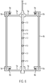
- An example where the connector device has two bearings is shown in Figure 6 .
- a second part 4b of the illumination component, in this example a lighting apparatus is rotatably supported at two different locations by the connector device.
- the first part 4a of the lighting apparatus i.e., the light-emitting device, includes at least one, in this example several, light-emitting elements 13, like LEDs or light bulbs, attached to a support element 14.
- the support element 14 has an elongated shape and the light-emitting elements are provided at different positions along the length of the elongated support element.
- any other type of light-emitting device may be used, for example a fluorescent tube.
- the second part 4b of the lighting apparatus i.e., the shell, also has an elongated shape and is arranged so as to at least partially encase the support element.
- the connector device comprises a first portion 5a and two bearings 8a and 8b.
- the first portion of the connector device has at least a first and a second piece.
- the first and second pieces are each attached to the first part 4a of the lighting apparatus, in this example to the support element, at different positions along the length of the support element, in particular, at different ends of the support element.
- the second portion 5b of the connector device also has at least a first and a second piece.
- the respective first pieces of the first and second portion of the connector device are connected via bearing 8a and the respective second pieces of the first and second portion of the connector device are connected via bearing 8b.
- the first piece of the first portion of the connector device is arranged at the end of the support element that is closer to the cable.
- the second piece and the second piece of the first portion of the connector device is arranged at the end of the support element that is further from cable.
- the first and second portion of the connector device and the bearings are arranged such that the second portion of the connector device is rotatably supported at two different locations, such that also the second part of the lighting apparatus is supported at two different locations.
- the connector device may have more than one bearing and be configured such that the first and second part of the illumination component are rotationally decoupled from the cable independently of each other, for example via separate bearings.
- the illumination component may have more than two parts.
- the connector device is configured such that other parts than the first and/or second part of the illumination component are rotationally decoupled from the cable, in particular, that they are decoupled from the cable independently from the first and/or second part.
Landscapes
- Engineering & Computer Science (AREA)
- General Engineering & Computer Science (AREA)
- Arrangement Of Elements, Cooling, Sealing, Or The Like Of Lighting Devices (AREA)
- Non-Portable Lighting Devices Or Systems Thereof (AREA)
- Installation Of Indoor Wiring (AREA)
- Details Of Connecting Devices For Male And Female Coupling (AREA)
Priority Applications (7)
| Application Number | Priority Date | Filing Date | Title |
|---|---|---|---|
| DK19168645.0T DK3722668T3 (da) | 2019-04-11 | 2019-04-11 | System, omfattende en belysningskomponent |
| EP19168645.0A EP3722668B1 (en) | 2019-04-11 | 2019-04-11 | System comprising an illumination component |
| ES19168645T ES2882781T3 (es) | 2019-04-11 | 2019-04-11 | Sistema que comprende un elemento de iluminación |
| PL19168645T PL3722668T3 (pl) | 2019-04-11 | 2019-04-11 | System zawierający oświetleniowy element składowy |
| JP2020071136A JP6961032B2 (ja) | 2019-04-11 | 2020-04-10 | 照明構成部材を備えるシステム |
| US16/845,680 US11118763B2 (en) | 2019-04-11 | 2020-04-10 | System comprising an illumination component |
| CN202010285453.9A CN111853622B (zh) | 2019-04-11 | 2020-04-13 | 包括照明组件的系统 |
Applications Claiming Priority (1)
| Application Number | Priority Date | Filing Date | Title |
|---|---|---|---|
| EP19168645.0A EP3722668B1 (en) | 2019-04-11 | 2019-04-11 | System comprising an illumination component |
Publications (2)
| Publication Number | Publication Date |
|---|---|
| EP3722668A1 EP3722668A1 (en) | 2020-10-14 |
| EP3722668B1 true EP3722668B1 (en) | 2021-07-07 |
Family
ID=66105185
Family Applications (1)
| Application Number | Title | Priority Date | Filing Date |
|---|---|---|---|
| EP19168645.0A Active EP3722668B1 (en) | 2019-04-11 | 2019-04-11 | System comprising an illumination component |
Country Status (7)
| Country | Link |
|---|---|
| US (1) | US11118763B2 (pl) |
| EP (1) | EP3722668B1 (pl) |
| JP (1) | JP6961032B2 (pl) |
| CN (1) | CN111853622B (pl) |
| DK (1) | DK3722668T3 (pl) |
| ES (1) | ES2882781T3 (pl) |
| PL (1) | PL3722668T3 (pl) |
Families Citing this family (1)
| Publication number | Priority date | Publication date | Assignee | Title |
|---|---|---|---|---|
| PL3722668T3 (pl) | 2019-04-11 | 2022-01-10 | Dark Matter Gmbh | System zawierający oświetleniowy element składowy |
Family Cites Families (30)
| Publication number | Priority date | Publication date | Assignee | Title |
|---|---|---|---|---|
| JPS5032822B1 (pl) * | 1970-07-31 | 1975-10-24 | ||
| JPS5340088U (pl) * | 1976-09-09 | 1978-04-07 | ||
| JPS57186916U (pl) * | 1981-05-22 | 1982-11-27 | ||
| JPS6033702U (ja) * | 1983-08-12 | 1985-03-07 | 共立金属株式会社 | 光熱式回転放光灯 |
| US4729071A (en) * | 1986-11-03 | 1988-03-01 | Altman Stage Lighting Co. | Low-inertial beam direction lighting system |
| JP2782571B2 (ja) * | 1993-02-09 | 1998-08-06 | 日本電設工業株式会社 | 照明装置 |
| JP2004200085A (ja) * | 2002-12-19 | 2004-07-15 | Matsushita Electric Works Ltd | 照明器具 |
| CN2747749Y (zh) * | 2004-10-27 | 2005-12-21 | 曹型勇 | 同轴式电器产品连接器 |
| DE102007026431B4 (de) * | 2007-06-06 | 2009-04-23 | Spinner Gmbh | HF-Drehkupplung mit Lambda/4-Leitung zwischen Stator und Rotor |
| CN101452791B (zh) * | 2007-11-29 | 2011-11-02 | 河南平高电气股份有限公司 | 户外高压隔离开关的电连接装置 |
| JP2010010124A (ja) * | 2008-05-28 | 2010-01-14 | Toshiba Lighting & Technology Corp | 照明装置 |
| KR20110012878A (ko) * | 2009-07-31 | 2011-02-09 | 이재규 | 조명본체 위치 조절장치 |
| US8434894B2 (en) * | 2009-11-16 | 2013-05-07 | Goal Zero Llc | Lighting apparatus; components thereof and assemblies incorporating the same |
| DK2466252T3 (da) | 2010-12-20 | 2013-07-29 | Christopher Bauder | Spil til tilvejebringelse af en forud bestemt længde af udrullet kabel |
| CN202008072U (zh) * | 2011-03-24 | 2011-10-12 | 肇庆市衡艺实业有限公司 | 旋转吊灯 |
| US9333904B2 (en) * | 2012-03-08 | 2016-05-10 | Koninklijke Philips N.V. | Controllable high luminance illumination with moving light-sources |
| DE102014109128A1 (de) * | 2014-06-30 | 2015-12-31 | Ahmet Balkaya | An einer Zimmerdecke befestigbare Vorrichtung zur Halterung eines elektrischen Verbrauchers, beispielsweise Leuchte oder Display |
| CN204141531U (zh) * | 2014-07-31 | 2015-02-04 | 中山市金霖电子科技有限公司 | 可旋转的螺旋led灯 |
| CN104132289B (zh) * | 2014-08-20 | 2015-06-03 | 阜南县天亿工艺品有限公司 | 多功能仿石灯笼的制作方法 |
| CN204313159U (zh) * | 2015-01-06 | 2015-05-06 | 台州市鸿基灯饰有限公司 | 方便安装的灯笼 |
| TWI559658B (zh) * | 2015-01-07 | 2016-11-21 | 建準電機工業股份有限公司 | 吊扇馬達 |
| JP6557354B2 (ja) * | 2015-11-18 | 2019-08-07 | マクセル株式会社 | 照明装置 |
| CN106764737A (zh) * | 2016-11-29 | 2017-05-31 | 成都汉能芯光电气有限公司 | 一种便于清洁更换的吊顶照明装置 |
| CN206310359U (zh) * | 2016-12-27 | 2017-07-07 | 广州市震泓光电科技有限公司 | 动力卷轴升降器及其升降灯 |
| CN206608346U (zh) * | 2017-03-24 | 2017-11-03 | 浙江炜宇通风机电有限公司 | 照明吊扇 |
| DK3608284T3 (da) | 2017-08-31 | 2021-01-25 | Dmitrijs Volohovs | Vinde |
| US10240766B1 (en) * | 2017-10-26 | 2019-03-26 | Kenneth Woodworth | Expandable LED light ball |
| CN208652351U (zh) * | 2018-09-03 | 2019-03-26 | 深圳市三肯光电有限公司 | 一种吊装长度可调的led飞碟灯 |
| DK3686149T3 (da) | 2019-01-24 | 2021-06-07 | Dmitrijs Volohovs | Vinde, og fremgangsmåde til at forhindre wireslaphed af en wirevinde |
| PL3722668T3 (pl) | 2019-04-11 | 2022-01-10 | Dark Matter Gmbh | System zawierający oświetleniowy element składowy |
-
2019
- 2019-04-11 PL PL19168645T patent/PL3722668T3/pl unknown
- 2019-04-11 DK DK19168645.0T patent/DK3722668T3/da active
- 2019-04-11 ES ES19168645T patent/ES2882781T3/es active Active
- 2019-04-11 EP EP19168645.0A patent/EP3722668B1/en active Active
-
2020
- 2020-04-10 JP JP2020071136A patent/JP6961032B2/ja active Active
- 2020-04-10 US US16/845,680 patent/US11118763B2/en active Active
- 2020-04-13 CN CN202010285453.9A patent/CN111853622B/zh active Active
Non-Patent Citations (1)
| Title |
|---|
| None * |
Also Published As
| Publication number | Publication date |
|---|---|
| JP6961032B2 (ja) | 2021-11-05 |
| PL3722668T3 (pl) | 2022-01-10 |
| US11118763B2 (en) | 2021-09-14 |
| ES2882781T3 (es) | 2021-12-02 |
| DK3722668T3 (da) | 2021-10-04 |
| CN111853622B (zh) | 2023-02-24 |
| US20200326055A1 (en) | 2020-10-15 |
| JP2020174041A (ja) | 2020-10-22 |
| CN111853622A (zh) | 2020-10-30 |
| EP3722668A1 (en) | 2020-10-14 |
Similar Documents
| Publication | Publication Date | Title |
|---|---|---|
| EP2466252B1 (en) | Winch for providing a predetermined length of unwound cable | |
| AU2017203944B2 (en) | Lighting elevating apparatus | |
| EP3115687B1 (en) | Lifting apparatus for highly mounted equipment | |
| US4112486A (en) | Remotely controlled positioning device for illuminating unit and the like | |
| CN102954449A (zh) | 高顶灯升降机构及高顶灯 | |
| EP3722668A1 (en) | System comprising an illumination component | |
| KR101114874B1 (ko) | 무대 설비용 케이블 릴 | |
| CN104613383A (zh) | 一种led灯 | |
| US20140319440A1 (en) | Electric hoist | |
| CN110282547B (zh) | 一种起升机构及起重机 | |
| CN115490098B (zh) | 一种免插拔绕线式自动收放线装置 | |
| CN215446259U (zh) | 灯具升降装置 | |
| US20100309014A1 (en) | Extending emergency light with a recessed, covered storage cavity | |
| CN202203683U (zh) | 移动式配电照明灯 | |
| CN102878537A (zh) | 天轴式灯光升降吊架 | |
| BR102016027746A2 (pt) | Lighting system | |
| CN217209015U (zh) | 一种可拼接灯模组 | |
| JP2010170875A (ja) | 昇降式照明器具 | |
| KR20180102272A (ko) | 법당내부의 led조명등 부착장치 | |
| CN117125642A (zh) | 升降机箱 | |
| WO1984002567A1 (en) | Lighting hoist | |
| JP2009545108A (ja) | 電子安定器を制御するための受光器を備える照明システム | |
| CN115862957A (zh) | 一种光电混合缆组装机构及电缆系统 | |
| JP2025045533A (ja) | 照明装置 | |
| JP2008087943A (ja) | エレベータ装置 |
Legal Events
| Date | Code | Title | Description |
|---|---|---|---|
| PUAI | Public reference made under article 153(3) epc to a published international application that has entered the european phase |
Free format text: ORIGINAL CODE: 0009012 |
|
| STAA | Information on the status of an ep patent application or granted ep patent |
Free format text: STATUS: REQUEST FOR EXAMINATION WAS MADE |
|
| 17P | Request for examination filed |
Effective date: 20200115 |
|
| AK | Designated contracting states |
Kind code of ref document: A1 Designated state(s): AL AT BE BG CH CY CZ DE DK EE ES FI FR GB GR HR HU IE IS IT LI LT LU LV MC MK MT NL NO PL PT RO RS SE SI SK SM TR |
|
| AX | Request for extension of the european patent |
Extension state: BA ME |
|
| GRAP | Despatch of communication of intention to grant a patent |
Free format text: ORIGINAL CODE: EPIDOSNIGR1 |
|
| STAA | Information on the status of an ep patent application or granted ep patent |
Free format text: STATUS: GRANT OF PATENT IS INTENDED |
|
| INTG | Intention to grant announced |
Effective date: 20201207 |
|
| RIN1 | Information on inventor provided before grant (corrected) |
Inventor name: LANGBEIN, JOHANNES |
|
| GRAJ | Information related to disapproval of communication of intention to grant by the applicant or resumption of examination proceedings by the epo deleted |
Free format text: ORIGINAL CODE: EPIDOSDIGR1 |
|
| STAA | Information on the status of an ep patent application or granted ep patent |
Free format text: STATUS: REQUEST FOR EXAMINATION WAS MADE |
|
| GRAP | Despatch of communication of intention to grant a patent |
Free format text: ORIGINAL CODE: EPIDOSNIGR1 |
|
| STAA | Information on the status of an ep patent application or granted ep patent |
Free format text: STATUS: GRANT OF PATENT IS INTENDED |
|
| INTC | Intention to grant announced (deleted) | ||
| TPAC | Observations filed by third parties |
Free format text: ORIGINAL CODE: EPIDOSNTIPA |
|
| INTG | Intention to grant announced |
Effective date: 20210208 |
|
| RAP3 | Party data changed (applicant data changed or rights of an application transferred) |
Owner name: DARK MATTER GMBH |
|
| GRAS | Grant fee paid |
Free format text: ORIGINAL CODE: EPIDOSNIGR3 |
|
| GRAA | (expected) grant |
Free format text: ORIGINAL CODE: 0009210 |
|
| STAA | Information on the status of an ep patent application or granted ep patent |
Free format text: STATUS: THE PATENT HAS BEEN GRANTED |
|
| AK | Designated contracting states |
Kind code of ref document: B1 Designated state(s): AL AT BE BG CH CY CZ DE DK EE ES FI FR GB GR HR HU IE IS IT LI LT LU LV MC MK MT NL NO PL PT RO RS SE SI SK SM TR |
|
| REG | Reference to a national code |
Ref country code: GB Ref legal event code: FG4D |
|
| REG | Reference to a national code |
Ref country code: AT Ref legal event code: REF Ref document number: 1408945 Country of ref document: AT Kind code of ref document: T Effective date: 20210715 |
|
| REG | Reference to a national code |
Ref country code: DE Ref legal event code: R096 Ref document number: 602019005828 Country of ref document: DE |
|
| REG | Reference to a national code |
Ref country code: IE Ref legal event code: FG4D |
|
| REG | Reference to a national code |
Ref country code: NL Ref legal event code: FP |
|
| REG | Reference to a national code |
Ref country code: DK Ref legal event code: T3 Effective date: 20210930 |
|
| REG | Reference to a national code |
Ref country code: LT Ref legal event code: MG9D |
|
| REG | Reference to a national code |
Ref country code: ES Ref legal event code: FG2A Ref document number: 2882781 Country of ref document: ES Kind code of ref document: T3 Effective date: 20211202 |
|
| REG | Reference to a national code |
Ref country code: AT Ref legal event code: MK05 Ref document number: 1408945 Country of ref document: AT Kind code of ref document: T Effective date: 20210707 |
|
| PG25 | Lapsed in a contracting state [announced via postgrant information from national office to epo] |
Ref country code: HR Free format text: LAPSE BECAUSE OF FAILURE TO SUBMIT A TRANSLATION OF THE DESCRIPTION OR TO PAY THE FEE WITHIN THE PRESCRIBED TIME-LIMIT Effective date: 20210707 Ref country code: PT Free format text: LAPSE BECAUSE OF FAILURE TO SUBMIT A TRANSLATION OF THE DESCRIPTION OR TO PAY THE FEE WITHIN THE PRESCRIBED TIME-LIMIT Effective date: 20211108 Ref country code: NO Free format text: LAPSE BECAUSE OF FAILURE TO SUBMIT A TRANSLATION OF THE DESCRIPTION OR TO PAY THE FEE WITHIN THE PRESCRIBED TIME-LIMIT Effective date: 20211007 Ref country code: BG Free format text: LAPSE BECAUSE OF FAILURE TO SUBMIT A TRANSLATION OF THE DESCRIPTION OR TO PAY THE FEE WITHIN THE PRESCRIBED TIME-LIMIT Effective date: 20211007 Ref country code: AT Free format text: LAPSE BECAUSE OF FAILURE TO SUBMIT A TRANSLATION OF THE DESCRIPTION OR TO PAY THE FEE WITHIN THE PRESCRIBED TIME-LIMIT Effective date: 20210707 Ref country code: LT Free format text: LAPSE BECAUSE OF FAILURE TO SUBMIT A TRANSLATION OF THE DESCRIPTION OR TO PAY THE FEE WITHIN THE PRESCRIBED TIME-LIMIT Effective date: 20210707 Ref country code: FI Free format text: LAPSE BECAUSE OF FAILURE TO SUBMIT A TRANSLATION OF THE DESCRIPTION OR TO PAY THE FEE WITHIN THE PRESCRIBED TIME-LIMIT Effective date: 20210707 Ref country code: SE Free format text: LAPSE BECAUSE OF FAILURE TO SUBMIT A TRANSLATION OF THE DESCRIPTION OR TO PAY THE FEE WITHIN THE PRESCRIBED TIME-LIMIT Effective date: 20210707 Ref country code: RS Free format text: LAPSE BECAUSE OF FAILURE TO SUBMIT A TRANSLATION OF THE DESCRIPTION OR TO PAY THE FEE WITHIN THE PRESCRIBED TIME-LIMIT Effective date: 20210707 |
|
| PG25 | Lapsed in a contracting state [announced via postgrant information from national office to epo] |
Ref country code: GR Free format text: LAPSE BECAUSE OF FAILURE TO SUBMIT A TRANSLATION OF THE DESCRIPTION OR TO PAY THE FEE WITHIN THE PRESCRIBED TIME-LIMIT Effective date: 20211008 |
|
| REG | Reference to a national code |
Ref country code: DE Ref legal event code: R097 Ref document number: 602019005828 Country of ref document: DE |
|
| PLBE | No opposition filed within time limit |
Free format text: ORIGINAL CODE: 0009261 |
|
| STAA | Information on the status of an ep patent application or granted ep patent |
Free format text: STATUS: NO OPPOSITION FILED WITHIN TIME LIMIT |
|
| PG25 | Lapsed in a contracting state [announced via postgrant information from national office to epo] |
Ref country code: SM Free format text: LAPSE BECAUSE OF FAILURE TO SUBMIT A TRANSLATION OF THE DESCRIPTION OR TO PAY THE FEE WITHIN THE PRESCRIBED TIME-LIMIT Effective date: 20210707 Ref country code: SK Free format text: LAPSE BECAUSE OF FAILURE TO SUBMIT A TRANSLATION OF THE DESCRIPTION OR TO PAY THE FEE WITHIN THE PRESCRIBED TIME-LIMIT Effective date: 20210707 Ref country code: RO Free format text: LAPSE BECAUSE OF FAILURE TO SUBMIT A TRANSLATION OF THE DESCRIPTION OR TO PAY THE FEE WITHIN THE PRESCRIBED TIME-LIMIT Effective date: 20210707 Ref country code: EE Free format text: LAPSE BECAUSE OF FAILURE TO SUBMIT A TRANSLATION OF THE DESCRIPTION OR TO PAY THE FEE WITHIN THE PRESCRIBED TIME-LIMIT Effective date: 20210707 Ref country code: AL Free format text: LAPSE BECAUSE OF FAILURE TO SUBMIT A TRANSLATION OF THE DESCRIPTION OR TO PAY THE FEE WITHIN THE PRESCRIBED TIME-LIMIT Effective date: 20210707 |
|
| 26N | No opposition filed |
Effective date: 20220408 |
|
| REG | Reference to a national code |
Ref country code: CH Ref legal event code: PL |
|
| REG | Reference to a national code |
Ref country code: BE Ref legal event code: MM Effective date: 20220430 |
|
| PG25 | Lapsed in a contracting state [announced via postgrant information from national office to epo] |
Ref country code: MC Free format text: LAPSE BECAUSE OF FAILURE TO SUBMIT A TRANSLATION OF THE DESCRIPTION OR TO PAY THE FEE WITHIN THE PRESCRIBED TIME-LIMIT Effective date: 20210707 Ref country code: LU Free format text: LAPSE BECAUSE OF NON-PAYMENT OF DUE FEES Effective date: 20220411 Ref country code: LI Free format text: LAPSE BECAUSE OF NON-PAYMENT OF DUE FEES Effective date: 20220430 Ref country code: CH Free format text: LAPSE BECAUSE OF NON-PAYMENT OF DUE FEES Effective date: 20220430 |
|
| PG25 | Lapsed in a contracting state [announced via postgrant information from national office to epo] |
Ref country code: BE Free format text: LAPSE BECAUSE OF NON-PAYMENT OF DUE FEES Effective date: 20220430 |
|
| PG25 | Lapsed in a contracting state [announced via postgrant information from national office to epo] |
Ref country code: IE Free format text: LAPSE BECAUSE OF NON-PAYMENT OF DUE FEES Effective date: 20220411 |
|
| PG25 | Lapsed in a contracting state [announced via postgrant information from national office to epo] |
Ref country code: MK Free format text: LAPSE BECAUSE OF FAILURE TO SUBMIT A TRANSLATION OF THE DESCRIPTION OR TO PAY THE FEE WITHIN THE PRESCRIBED TIME-LIMIT Effective date: 20210707 Ref country code: CY Free format text: LAPSE BECAUSE OF FAILURE TO SUBMIT A TRANSLATION OF THE DESCRIPTION OR TO PAY THE FEE WITHIN THE PRESCRIBED TIME-LIMIT Effective date: 20210707 |
|
| PG25 | Lapsed in a contracting state [announced via postgrant information from national office to epo] |
Ref country code: HU Free format text: LAPSE BECAUSE OF FAILURE TO SUBMIT A TRANSLATION OF THE DESCRIPTION OR TO PAY THE FEE WITHIN THE PRESCRIBED TIME-LIMIT; INVALID AB INITIO Effective date: 20190411 |
|
| PG25 | Lapsed in a contracting state [announced via postgrant information from national office to epo] |
Ref country code: MT Free format text: LAPSE BECAUSE OF FAILURE TO SUBMIT A TRANSLATION OF THE DESCRIPTION OR TO PAY THE FEE WITHIN THE PRESCRIBED TIME-LIMIT Effective date: 20210707 |
|
| PG25 | Lapsed in a contracting state [announced via postgrant information from national office to epo] |
Ref country code: TR Free format text: LAPSE BECAUSE OF FAILURE TO SUBMIT A TRANSLATION OF THE DESCRIPTION OR TO PAY THE FEE WITHIN THE PRESCRIBED TIME-LIMIT Effective date: 20210707 |
|
| PGFP | Annual fee paid to national office [announced via postgrant information from national office to epo] |
Ref country code: PL Payment date: 20260330 Year of fee payment: 8 |
|
| PGFP | Annual fee paid to national office [announced via postgrant information from national office to epo] |
Ref country code: NL Payment date: 20260428 Year of fee payment: 8 |
|
| PGFP | Annual fee paid to national office [announced via postgrant information from national office to epo] |
Ref country code: ES Payment date: 20260504 Year of fee payment: 8 |
|
| PGFP | Annual fee paid to national office [announced via postgrant information from national office to epo] |
Ref country code: GB Payment date: 20260427 Year of fee payment: 8 Ref country code: DK Payment date: 20260428 Year of fee payment: 8 |
|
| PGFP | Annual fee paid to national office [announced via postgrant information from national office to epo] |
Ref country code: IT Payment date: 20260428 Year of fee payment: 8 |
|
| PGFP | Annual fee paid to national office [announced via postgrant information from national office to epo] |
Ref country code: DE Payment date: 20260427 Year of fee payment: 8 |
|
| PGFP | Annual fee paid to national office [announced via postgrant information from national office to epo] |
Ref country code: CZ Payment date: 20260331 Year of fee payment: 8 |
|
| PGFP | Annual fee paid to national office [announced via postgrant information from national office to epo] |
Ref country code: FR Payment date: 20260429 Year of fee payment: 8 |
|
| PGFP | Annual fee paid to national office [announced via postgrant information from national office to epo] |
Ref country code: LV Payment date: 20260422 Year of fee payment: 8 |